

Page 1
MENU SYSTEM MANUAL
MENUSYSTEMVEJLEDNING
VALIKKOJÄRJESTELMÄN OPAS
MENÜ-SYSTEMHANDBUCH
MENY SYSTEM MANUAL
Page 2

Page 3

Contents
1. THE DEDICATED MICROS TYPE 2060 DOME CAMERA 3
2. THE DEDICATED MICROS TYPE 2040 DOME CAMERA 5
3. PROGRAMMABLE FEATURES 7
3.1 Preset Positions 7
3.2 Preset Position Titles 7
3.3 Tours 7
3.4 Real Time Clock 7
3.5 Alarm Response 7
3.6 Bottom Flip 8
3.7 Camera Mode 8
3.8 Digital Zoom Extension 8
3.9 Dome Selection Cursor 8
3.10 Text Positioning and Selection 8
3.11 Joystick Range 8
3.12 Host polling 8
3.13 Error Reporting 9
3.14 Activity light 9
3.15 User Timeout 9
3.16 Set Video Amplification 9
3.17 Privacy mode 9
4. OPERATION WITH A CONTROL PANEL 10
4.1 Dome Menu Structure with Dennard/DM controllers 10
4.2 Main Menu 11
4.2.1 Go to Preset or Start Tour 11
.2.2 PIN number entry 12
4.3 Supervisor Menu 15
4.3.1 Store/Edit Preset 15
4.3.2 Store/Edit Tour 16
4.3.3 Alarm Setup 17
2040 / 2060 Menu System Manual Page. 1
Page 4

4.3.4 Supervisor Options 19
4.3.5 Enter New PIN 22
4.3.6 Privacy Zone Setup 22
4.4 Technician Menu 23
4.4.1 Camera set up 23
4.4.2 Enable/Disable options 24
4.4.3 Joystick control 24
4.4.4 Miscellaneous Services 25
4.4.5 Enter New PIN 26
5. MENU FLOW CHART 27
6. ALTERNATIVE CONTROLLERS 31
6.1 Dedicated Micros Digital Sprite 2 31
6.1.1 Up the coax control 31
6.1.2 RS485 control 32
6.2 Baxall / Vista controllers 32
6.3 Dennard/DM dtx1000/dc 33
6.4 Building Block Video TX1000/DC 34
6.5 Dennard/DM dtx400/dc 35
6.6 Building Block Video TX400DC 36
7 TROUBLE SHOOTING GUIDE 37
2040 / 2060 Menu System Manual Page. 2
Page 5

1. THE DEDICATED MICROS TYPE 2060 DOME CAMERA
The Dedicated Micros 2060 Dome Camera is a precision unit, offering a wide variable speed range,
together with a large pre-set memory for positions, tours and alarm responses. It has a switchable
colour/monochrome camera (colour-only on indoor units) with an 18:1 zoom lens plus x 4 digital
enhancement.
The unit has a comprehensive set of features as standard, which can be tailored for individual
preferences. These can be accessed through an internally generated set of menus overlaid on the
video signal if the controller does not have a suitable layout. Each Dome Camera is delivered with a
separate weatherproof power supply.
Outline Specification:
2040 / 2060 Menu System Manual Page. 3
Speed range 0.05 to 300 º / second max (both Pan and Tilt)
Repeatability 5 minutes of arc
Control
RS 485 half duplex or simplex, 9600 Baud OR ‘Up the coax’ using
built in DEN PANEL or BAX PANEL protocol converter for
Dennard/DM, BBV & DM or Baxall controls
Storage capacity
200 positions, with identifying title of up to 20 characters
100 tours of up to 16 preset positions
100 deep alarm response memory
Power Supply
24Va.c, Camera & control electronics:-10VA
Heater & blower unit:-10VA
Dimensions
Dome Camera: 150mm diameter hemisphere x 230mm overall
Power Supply: 165L x 135W x 95H.
Protection BS EN 60529 to level IP66 (no water ingress)
Weight
Dome Camera: 1.7 kg + mounting bracket
Power Supply: 1.3 kg
Mounting Configurations
Ceiling mount, pendant mount, wall bracket, corner mount, snowdrop
& tile mounts available
Page 6

18X zoom camera module
26X zoom camera module
2040 / 2060 Menu System Manual Page. 4
Optical range
4.1mm to 73.8mm zoom; F1.4 to F3.0
Auto-focus with manual override
Privacy zones 24 programmable zones (8 on screen at any time)
Video sensitivity 0.7 lux colour
Video resolution
768 horizontal x 494 vertical, pixels
More than 470 TVL
Video output 1.0v p-p composite, negative synch
Optical range
3.5mm to 91.0mm zoom; F1.6 to F3.8
Auto-focus with manual override
Privacy zones 24 programmable zones (8 on screen at any time)
Video sensitivity 1.0 lux colour
Video resolution
768 horizontal x 494 vertical, pixels
More than 470 TVL
Video output 1.0v p-p composite, negative synch
Page 7

2. THE DEDICATED MICROS TYPE 2040 DOME CAMERA
The Dedicated Micros 2040 Dome Camera is a precision unit, offering a wide variable speed range,
together with a large pre-set memory for positions, tours and alarm responses. It has a colour
camera with a 18:1 zoom lens.
The unit has a comprehensive set of features as standard, which can be tailored for individual
preferences. These can be accessed through an internally generated set of menus overlaid on the
video signal if the controller does not have a suitable layout.
Outline Specification:
2040 / 2060 Menu System Manual Page. 5
Speed range 0.05 to 300 º / second max (both Pan and Tilt)
Repeatability 5 minutes of arc
Control
RS 485 half duplex or simplex, 9600 Baud OR 'Up the coax' using
built in DEN PANEL or BAX PANEL protocol converter for
Dennard/DM, BBV & DM or Baxall controls
Storage capacity
100 positions with identifying title of up to 20 characters
50 tours of up to 16 preset positions
50 alarm responses
Power Supply 24Va.c, camera & control electronics; 10VA
Dimensions
150mm diameter hemisphere with 220mm ceiling ring
110mm height behind ceiling panel
Weight 1.5 kg
Mounting Configurations Tile mount.
Page 8

18X zoom camera
2040 / 2060 Menu System Manual Page. 6
Optical range
4.1mm to 73.8mm optical zoom; F1.4 to F3.0
Auto focus with manual override
Privacy zones 24 programmable zones with 8 on screen at any time
Video sensitivity 3 Lux colour
Video resolution
768 horizontal x 494 vertical, pixels
More than 470 TVL
Video output 1.0v p-p composite, negative sync
Page 9

3. PROGRAMMABLE FEATURES
The Dedicated Micros 2060/2040 Dome Camera's have a number of features which can be
selected by the System Supervisor when the dome is installed. Any of these can be altered
subsequently, or cancelled altogether, to give the best operational responses for any particular
application. They are invoked or cancelled through on-screen menu structures, described in section
4, and the settings are then retained in non-volatile memory so that they are not affected by a loss
of power.
The features, and what they offer, are described below:
3.1 Preset Positions
Up to 200 (2060) or 100 (2040) positions can be stored and recalled at any time. Each position
stores the Pan, Tilt, Zoom, and Focus positions as well as the position title.
3.2 Preset Position Titles
Each preset position title can have up to 20 alphanumeric characters to identify the associated
position uniquely. The default title position lies at the top left hand corner of the video picture, left
justified, but this can be altered if required.
The preset position titles only appear at the position they identify: any movement from that position
will remove them.
3.3 Tours
Up to 100 (2060) or 50 (2040) tours can be stored and recalled at any time. Each tour can contain
up to 16 positions together with a ‘Dwell’ time at each position plus the ‘Travel Time’ that the dome
unit must take to reach the next position. When the last position in the tour is reached, the tour
‘loops’ back to the first position.
3.4 Real Time Clock (Not applicable to the 2040)
The 2060 dome camera is fitted with a real time clock to provide time and date marks for the
operator and the recording system if required. A range of selectable formats can provide time and
date displays and the unit is able to use the information to provide enhanced alarm functions where
the reaction to an alarm can be modified depending on the time of day or the day of the week.
3.5 Alarm Response
Up to 100 (2060) or 50 (2040) Alarm responses can be stored. Each alarm response creates a
specified reaction to an alarm number. This is a very powerful feature, allowing a number of domes,
or any other device conforming to the Dennard/DM protocol, to invoke a pre-set alarm action from
one single loop broadcast command.
2040 / 2060 Menu System Manual Page. 7
Page 10

3.6 Bottom Flip
The dome will automatically pan through 180 degrees as fast as possible when tilted fully down so
that it is possible to follow a person or car, moving directly underneath the dome, with only a single
joystick direction to consider.
3.7 Camera Mode
The camera in both 2060 and 2040 can be switched between colour and monochrome mode. In the
2060 it can be selected as colour/mono in which case it will automatically switch to mono when the
light level is insufficient for good quality colour pictures.
3.8 Digital Zoom Extension
The camera system allows an extension of the optical zoom by selecting more of the central part of
the picture and expanding this to fill the frame. This feature is selectable.
3.9 Dome Selection Cursor
The menu structure itself, and the choices and selections offered, are searched and invoked by a
single cursor or flashing character and the direction in which this moves depends on the particular
control panel in use. The direction of movement can be reversed separately for horizontal and
vertical movement if required.
3.10 Text Positioning and Selection
All text can be positioned where it is wanted, replaced with default text (eg: Position 31, or Sector
18), or removed as required.
3.11 Joystick Range
Even if the control panel has a wide range proportional joystick output, the Dedicated Micros Dome
has such a wide speed range that both a fast and a slow speed range are needed to realise the full
performance (provided of course that the control panel in question has a facility to invoke these
separately).
The slow speed range is simply the same as the fast speed range following the same in-built
correlation law, but divided by a constant. This constant can be set between 2 and 128.
3.12 Host polling
When the dome is configured for communication using RS485 protocols it can be set to check its
communication link at regular intervals. If a continuous data stream is expected from the controller,
enabling Host Polling will get the dome to report a communications error if nothing is received for 5
seconds. Normally, this setting is disabled.
2040 / 2060 Menu System Manual Page. 8
Page 11

3.13 Error Reporting
The Dedicated Micros Dome constantly monitors its own health and is able to indicate that a
problem has occurred by a flashing square in the top right hand corner of the transmitted picture.
The cause can subsequently be requested when convenient. Alternatively, the unit can display the
error text instead of the flashing square.
3.14 Activity light
A green LED provides some diagnostic help when first switching the dome on and also indicates
when command signals are received. As it may be visible externally it can be switched on or off.
3.15 User Timeout
There is a possibility that the dome may be left pointing at an unhelpful scene and, for whatever
reason, ‘forgotten’. To cater for this eventuality, two settings have the specific function of acting to
prevent this happening. These are Preset 001 and Tour 001.
A time delay can be set between 1 and 999 seconds and a default response to the timeout being
reached also defined. If the time is exceeded after any joystick/key entry Pan and Tilt input at the
Control Panel then the default action will occur.
If a delay time of 0 is set, no default action will occur and the unit will wait indefinitely for the next
user input.
If a Dome menu screen is left waiting for an input for more than 3 minutes then the system times
out and the dome resumes its previous activity.
3.16 Set Video Amplification
This facility allows the video gain to be adjusted from the normal setting, with four levels available.
Video lift can be tuned on or off and is normally set to the Off position.
3.17 Privacy mode
It is sometimes desirable to prevent operators from viewing certain areas. To meet this requirement
the Privacy mode allows black patches to be set up to cover these areas.
The size of the patch overlaid is the size of the monitor view at whatever zoom setting is used.
When zooming out, the patch reduces in size so that it only covers the original area.
2040 / 2060 Menu System Manual Page. 9
Page 12

4. OPERATION WITH A CONTROL PANEL
NB: This will vary between control panels. Please refer to the Controller manual.
The Dome Camera's are an open protocol device. Consequently, there are several different
manufacturers’ controllers available to drive it. All of the many features offered by the dome are
programmed from one of three menu structures. Each controller will have individual control
configurations which make it essential that the user reads the controller manual to ascertain which
button activation gives access to the menu features. Section 6 gives these functions for several
popular controllers.
The following instructions will guide you through the menu structure when using the Dome & PSU
(with address set to No. 253… DEN PANEL) controlled by either a Dennard/DM dtx400dc or
dtx1000dc
4.1 Dome Menu Structure with Dennard/DM controllers
The Menus appear on the screen when activated by the following commands:
Note that the ‘shift’ key must be held down while the selection is made.
On activation, the menu will appear on the monitor screen against the normal video scene
background with a cursor on the left hand edge. A choice is made by positioning the cursor over the
desired feature and operating an “ACCEPT” button(s) which, for the Dennard/DM controllers, is as
follows:-
For dtx1000dc, hold the preset button and press CAMERA SELECT 1
For dtx 400dc, press preset 1 button
2040 / 2060 Menu System Manual Page. 10
dtx1000dc access dtx400dc access
User Menu shift wash shift 1
Supervisor Menu (password required) shift wipe shift 2
Technicians Menu (password required) shift autopan shift 3
Page 13

4.2 Main Menu
When called, the Main Menu screen will display the following options, against a camera display
background, with a cursor at the left hand edge:
Using the joystick, or direction arrow keys, move up or down the list to select the feature required
then press the appropriate key(s) to accept/select it. If ‘Exit’ is chosen the menu is cleared and no
other action is taken by the dome.
4.2.1 Go to Preset or Start Tour
These selections allow the operator to recall the full range of stored Preset positions and Tours,
even if the control panel has neither the numerical range nor general ability to do so.
Note that this screen only allows existing preset positions and tours to be accessed. To set
up new presets or tours, see section 4.3.1 or 4.3.2
The display will prompt for the required numerical entry with the following subsidiary menu:
The cursor can be moved across the numerical line, using the joystick or control buttons, until the
desired number is reached. The characters will flash their position in turn and, as soon as one is
selected with the ACCEPT button(s), will be displayed in the _ _ _ part of the display.
Leading zeros need not be entered (eg 001 may be entered simply as ‘1’) but the entry must be
within range, eg 001 - 250 for Presets and 001 - 100 for Tours (2060) and 001 - 100 for Presets
and 001 - 50 for Tours (2040). Entries outside the range will cause an ‘Illegal Entry’ message to
flash, and the entry must be cleared and re-entered.
When the digits have been selected, Accept Entry will invoke that choice and the screen will
automatically clear to the desired camera position.
2040 / 2060 Menu System Manual Page. 11
Go to Preset
Start Tour
Technician Menu
Supervisor Menu
Exit
Preset Number___ (orTourNumber)
0123456789
Accept Entry
Clear Entry
Return
Page 14

To change the choice, ‘Clear Entry’ will start the process again.
Note that Preset number 1 and Tour number 1 should be allocated to the most common or
important views. These values are the ones to which the dome automatically returns
following a power cut if no operator is in attendance. See the section on power fail, sec
4.4.2.
4.2.2 PIN number entry
When the Technician or Supervisor menu is called the following screen appears. The password
or PIN Number is keyed in using the same method as used with previous entries.
The cursor is run across the numerical line, using the joystick or control buttons, until the desired
number is reached. The characters will flash their position in turn and as soon as one is selected
with the ACCEPT button(s) it will be displayed in the _ _ _ _ part of the display.
When all four digits have been selected, Accept Entry will invoke that choice and the screen will
automatically change to the selected menu i.e. the Technician or Supervisor menu.
2040 / 2060 Menu System Manual Page. 12
Enter PIN____
0123456789
Accept Entry
Clear Entry
Cancel
Page 15

THE FACTORY SET PASSWORDS (PINs), WHICH CAN BE
CHANGED BY THE TECHNICIAN OR SUPERVISOR IN THEIR
RESPECTIVE MENUS, ARE PRINTED BELOW.
TO PREVENT UNAUTHORISED CHANGES BEING MADE TO
SETTINGS OR STORED CAMERA POSITIONS, IT IS ADVISED
THAT PIN NUMBERS ARE KEPT IN A SAFE PLACE.
IF IT IS FELT NECESSARY, CUT THIS PAGE OUT OF THE
MANUAL.
2040 / 2060 Menu System Manual Page. 13
To gain access to the Supervisor Menu, enter PIN as ‘1111’
To gain access to the Technician Menu, enter PIN ‘9999’
Page 16

2040 / 2060 Menu System Manual Page. 14
Page 17

4.3 Supervisor Menu
The SUPERVISOR MENU allows the supervisor not only to duplicate the operator menu functions,
but also to programme Preset positions (with their identifying title) and Tours. Additionally, cursor
setting and text positioning and selection are accessed here.
The functions are split into a series of underlying menus in ‘layers’. When returning from most
underlying menus, the overlying menu is re-presented. The functions which are less likely to be
needed lie deeper in the structure.
The Supervisor Menu displays:
4.3.1 Store/Edit Preset
The first option enables the supervisor to define a view (including pan, tilt and zoom settings) and
store it for future recall. Note that storing a Preset requires that the desired camera view is already
visible when this screen is entered. Selecting this option calls up the following underlying screens.
Selecting the preset number is achieved as with the previous numerical entry screens. When the
number is accepted, a new display will allow the supervisor to give this position a name (such as
‘Main Gate’ or ‘Front Door’) or use the default names stored in the dome software. The screen will
prompt with:
Edit Preset Text -
Yes
No
Preset Number___
0123456789
Accept Entry
Clear Entry
Return Without Change
Delete Preset
Store/Edit Preset
Store/Edit Tour
Alarm Setup
Supervisor Options
Change PIN
Privacy Zone Setup
Return
Exit
2040 / 2060 Menu System Manual Page. 15
Page 18

Select ‘No’ to use the default names or ‘Yes’ to enter a new name through the following screen.
The title choice is made as usual with the cursor and accepted when ready (which will store the
chosen Title with the stored Preset position). Backspace allows a correction to be made while
‘Return without change’ will store the Preset position with the default title. The title appears in the _
_ space as it is compiled.
Note that the _’s shown here only indicate where this happens - they do not appear on the
screen
4.3.2 Store/Edit Tour
A Tour is a predefined journey taken by the camera, between a number of Preset positions. Before
accessing this facility, ensure that all the required Preset positions have been stored, as shown in
section 4.3.1. Choosing to program a Tour first requires the Tour Number to be entered in an
identical procedure to selecting a Position (except that the range must lie between 001 and 100).
Once the number has been accepted, a subsidiary menu is displayed:
If a tour has already been established on this number its initial data is displayed as ‘Old’. This data
can be edited by adding new values or a new tour can be established.
Here the entry format follows the now-familiar procedure but the _ _ _ characters have specific
functions: The first three characters, PPP, represent a Preset position number. ‘DD’ is the dwell
time that the camera must spend stationary at that position and ‘SS’ represents the time that the
camera must take to reach the next position in the tour. The times are entered as seconds,
between 01 and 99. If no value is entered, the Tour will use the default values of 2 seconds dwell
time and 3 seconds travel time.
When all characters are completed and then accepted, the display clears the entry ready to receive
the next position information and the ‘Item’ counter is incremented. When all entries are complete,
select the ‘Store Tour’ instruction.
2040 / 2060 Menu System Manual Page. 16
ABCDEFGHIJKLMNOPQRSTUVWX
YZabcdefghijklmnopqrstuv
wxyz0123456789:/*=+.-
Backspace
Return Without Change
Accept Entry
____________
Item___intour___
PPPDDTT
Old_______
New_______
0123456789
Accept Entry
Clear Entry
Return Without Change
Store Tour
Page 19

4.3.3 Alarm Setup
Alarms are inputs into the dome which require the dome to undertake a specific action. They may
come from a number of external sources, such as door entry systems or PIR motion sensors. The
2060 dome has a clock function that enables the supervisor to select different actions depending on
the time of day or the day of the week. This clock function is not available in the 2040, go to section
4.3.3.1. The Alarm Setup screen provides access to three options:
4.3.3.1 Alarm Action Setup
On selecting this function the supervisor must select an alarm number in the usual way with the
following screen:
Accepting the Alarm number brings up the following screen:
This allows a specified preset position P or tour T to be stored, along with its identification number
‘nnn’ which will be implemented when the alarm is activated. To select an option, use the code ‘01’
for Tour or ‘10’ for Preset (the 1 under the P or T selects its use; 11 is invalid). Accepting the entry
will increment the alarm number allowing all inputs to have an action allocated to them or their
existing action, shown as ‘Old’, modified. The alarm action will be sustained for a duration set by
the user timeout (see section 4.3.4.1).
2040 / 2060 Menu System Manual Page. 17
Alarm Action Setup
Mask Alarm
Select Holidays
Return
Exit
Alarm Number___
01234567890
Accept Entry
Clear Entry
Return Without Change
Delete Alarm
Alm___Select P or T
PTnnn
Old____
New____
0123456789
Accept Entry
Clear Entry
Return Without Change
(This screen is not applicable to 2040)
Page 20

4.3.3.2 Mask Alarms (Not Applicable to 2040)
Alarm responses can be modified, depending on when they are activated. Selecting this facility will
bring up the following screen:
The letters displayed indicate:
MTWTFSS Monday to Sunday
H Holiday
hhmm Time of ‘Mask On’
hhmm Time of ‘Mask Off’
Entering a ‘1’ under a day of the week means that the alarms will be masked – i.e. they will not
cause a response from the dome – on that day. Similarly, a ‘1’ under the Holiday means that the
alarm is masked on specified holidays (note that the setting for a holiday will override the setting for
a day of the week). The mask will operate throughout the days selected unless a mask on and off
time are entered. This is achieved through numerical entry of the time using the 24hr clock. The
mask temporarily disables all connected alarms.
For example, if motion sensors have been connected into the dome but are only required to
operate outside of normal working hours they can be masked by entering the code
‘1111100008301800’. This masks the alarms on Mon – Fri between 08.30 a.m and 6 p.m. Outside
these times, and at the weekends and on holidays, the dome will respond to the alarms as desired.
To add complete flexibility, up to ten levels of configuration are available, indicated by the ‘Item
number’ on the screen. As each entry is accepted the number increments until the full action is
saved. Secondary levels allow different masking times to be selected on different days. In the
example above, it may be that the building closes early on Friday. To achieve the different times,
the first code (item) would be modified to ‘1111000008301800’ and a second item code entered as
‘0000100008301400’. Now, the first mask only applies from Monday to Thursday while the second
level masks the alarms on Fridays, between 8.30 a.m. and 2 p.m. More complex masks can be built
up using the same logic for more variations.
4.3.3.3 Select Holidays (Not Applicable to 2040)
Up to 15 days can be programmed in as holidays, to cover periods such as Christmas or Bank
Holidays, when the alarm action may require modification. When the option is selected the following
screen is displayed:
2040 / 2060 Menu System Manual Page. 18
Item___ofAlarm Mask
PTWTFSSHhhmmhhmm
Old______________
New____
0123456789
Accept Entry
Clear Entry
Return Without Change
Save and Return
__________
Page 21

Dates can now be entered (e.g. 2512 for Christmas Day) to define the holidays for the year.
Accepting each entry will bring up a prompt for the next one. Select ‘Save and Return’ when
complete.
Note that some dates, such as Bank Holidays, may need to be reassigned at the start of a
new year.
4.3.4 Supervisor Options
A number of functions are grouped under the Supervisor Options category. Most of these alter the
way in which text and information is presented to the operator but there are some camera settings
which can be altered to suit the installation requirements. Selecting the options menu brings up the
following screen:
The first three options relate to camera facilities and are all set in the same way. To change the
setting, move the cursor up/down until it is alongside the feature. Moving the joystick to the left or
right (or pressing the left/right direction arrows) will scroll through alternative settings. Moving up or
down will fix the value on the screen. If the digital zoom is enabled the feature is automatically
invoked by the camera when the zoom control is held in after the optical zoom has reached its
mechanical end stop. The 2040 screen allows the supervisor to select a language in the same way.
The digital zoom setting is stored with any preset positions, but if the digital zoom option is later
disabled, the preset positions involved will only return the position with the optical zoom at full
extension.
The bottom flip facility may be used to track objects moving directly under the dome. With this
disabled, the camera view can be moved down until it looks directly under the dome but remains in
that orientation. With bottom flip enabled, the camera will be automatically rotated through 180oto
allow the operator to track the object as it moves on, away from the dome. The freeze frame option,
when selected, will hold the last view on the display while the dome moves at full speed to a preset
position. On arrival, the normal image view is displayed. This avoids a blur as the dome moves at
high speed to preset positions.
2040 / 2060 Menu System Manual Page. 19
Item___ofHoliday Days
ddmm
Old______________
New____
0123456789
Accept Entry
Clear Entry
Return Without Change
Save and Return
__________
Digital zoom: disabled
Bottom flip:
Freeze frame:
Set User Timeout:
Set Date/Time/Language
Preset Text Options
Back
Exit
enabled
disabled
none
(No Date/Time in 2040)
Page 22

4.3.4.1 Set User Timeout
The user timeout facility can be used to select what the dome should do if it is left idle by the
operator. Selecting this option will bring up the following screen:
The screen allows for the selection of a default timeout from 1 - 999 seconds entered as ‘SSS’.
This is the time between the last joystick (or P/T keys) input from the operator, and an automatic
move to the start of the default Tour or to the default Position, provided these have been
programmed. The value for ‘PT’ defines which action to take. Entering code 01 will select the Tour
and 10 will select the Preset position (11 is an illegal entry).
Accepting the entry will return the supervisor to the Options menu and the time selected will be
displayed on the screen. If a timeout of zero is selected, the display will show ‘none’ and the dome
will wait indefinitely for the next operator action.
4.3.4.2 Set Date/Time/Language (Not Applicable to 2040)
The 2060 dome has a Real Time Clock which must be set up on installation. Your unit may also
contain other language options and an ability to select and change the format for the time display.
Selecting this option brings up the following screen:
The first three options are all set in the same way. To change the setting, move the cursor up/down
until it is alongside the feature. Moving the joystick to the left or right (or pressing the left/right
direction arrows) will scroll through alternative settings. Moving up or down will fix the value on the
screen.
The time and date format determine the way in which the normal operator viewing screen displays
the time and date. Several options are available by scrolling through the list and it is also possible
to switch the time and date display off if preferred.
2040 / 2060 Menu System Manual Page. 20
SSSPT
Old____
New____
0123456789
Accept Entry
Clear Entry
Return Without Change
Language: English
Date Format:
Time Format:
Set Time and Date
Save and Return
Save and Exit
dd-mm-yy
hh:mm:ss
Page 23

When setting the time or date the following screen is presented:
Using the numerical entry, the current date and time can be entered or the existing values left
unchanged.
4.3.4.3 Preset Text Options
The names allocated to preset camera views can be created individually or a default name can be
allocated. This default name is pre-programmed as “Position” but this can be changed if required by
using this facility. The location of the name on the screen can also be adjusted. The following
screen is presented:
The preset position name can be displayed on the left or right of the screen or switched off by
selecting the appropriate feature and moving left/right to toggle the value. If the default name needs
to be altered then selecting the Edit facility will bring up the virtual keyboard used to enter the
name:
The choice is made as usual with the cursor and accepted when ready (which will store the chosen
Title as the default name). Backspace allows a correction to be made while ‘Return without change’
will leave the default name unchanged.
Note that the _’s shown here only indicate where this happens - they do not appear on the
screen.
2040 / 2060 Menu System Manual Page. 21
yymmddhhmm
Old_______
New_______
0123456789
Accept Entry
Clear Entry
Return Without Change
Preset txt justify: L
Default preset txt:
Edit default text
Return
Exit
On
ABCDEFGHIJKLMNOPQRSTUVWX
YZabcdefghijklmnopqrstuv
wxyz0123456789:/*=+.-
Backspace
Return Without Change
Accept Entry
____________
Page 24

4.3.5 Enter New PIN
The PIN number for the supervisor is pre-programmed but can be changed by the supervisor
through the following screen:
Key in your new PIN (password) and accept the entry.
Make a note of the new PIN number and keep it in a safe place
4.3.6 Privacy Zone Setup
The final option on the Supervisor Menu allows specific areas within view of the camera to be
blanked out, preventing the operator from monitoring or storing the images from those areas.
Before selecting the feature, ensure that the camera is positioned so that the required area to be
blocked is shown full screen on the monitor. The feature then allows the following options:
Selecting ‘Define single zone’ will make the screen go black as the patch is inserted. As the dome
has returned to normal mode, out of the screen settings, move the camera view away from the area
and the black section will remain in its specific location.
When defining multiple zones the screen will go black and the text ‘Privacy zones’ will be displayed.
Move the camera to the desired area and press ‘Enter’ for each zone. When finished, use the key
sequence to enter the menu structure (e.g. #1 for the dtx400) to escape from the feature.
To clear a privacy zone, the camera must be positioned over the zone before selecting the ‘Clear’
facility or the “Clear all privacy zones” feature selected. The dome will immediately return to normal
operation after the zone(s) has been deleted.
2040 / 2060 Menu System Manual Page. 22
Enter new PIN____
0123456789
Accept Entry
Clear Entry
Return Without Change
Define single zone
Clear single zone
Define multiple zones
Clear all privacy zones
Return
Exit
Page 25

4.4 Technician Menu
The Technician menu provides access to a number of features to determine overall dome operating
configurations. This menu will be little used after the dome is first installed and commissioned.
When called, it displays:
4.4.1 Camera set up
A number of changes can be made to the operation of the camera module inside the dome. The
following screen is used:
The options are all set in the same way. To change the setting, move the cursor up/down until it is
alongside the feature. Moving the joystick to the left or right (or pressing the left/right direction
arrows) will scroll through alternative settings. Moving up or down will fix the value on the screen.
When col/mono is selected the camera will operate in colour mode until the light level falls below a
predetermined value when it will automatically switch to mono mode. The reverse will occur when
the light returns to a suitable level for colour operation. The camera may also be fixed in colour or
mono mode if preferred.
When a preset position is stored the focus position of the lens is also stored. If the preset focus is
set to ‘auto’ (the preferred setting) the camera will refocus itself to cope with any changing
circumstances. Setting this to manual will force the original focus setting onto the camera while it
remains at the preset position.
The Near focus setting may be used in indoor applications as it allows the camera to focus at
objects less than a metre away. This should be disabled for normal outdoor operation as, otherwise,
it will auto focus onto raindrops that fall on the hemisphere.
If the frame integration is set to ‘auto’ the camera is able to adjust its frame rate to suit low light
applications. If ‘normal’ is selected, the frame rate will remain constant but the image quality may
suffer in low light.
2040 / 2060 Menu System Manual Page. 23
Camera set up
Enable/Disable options
Joystick control
Miscellaneous Services
Change PIN
Return
Exit
Camera colour: col/mono
Preset focus:
Near focus:
Frame integ: auto
Save and Return
Save and Exit
auto
disabled
Page 26

4.4.2 Enable/Disable options
A number of settings are available to allow the Technician to reposition text and determine suitable
action when errors occur. Selecting this brings up the following screen:
The options are all set in the same way. To change the setting, move the cursor up/down until it is
alongside the feature. Moving the joystick to the left or right (or pressing the left/right direction
arrows) will scroll through alternative settings. Moving up or down will fix the value on the screen.
The ‘Text edit’ option determines whether screen text will be edited locally, that is selected from the
dome’s own screen options; or whether it is compiled at the system Control Panel and transferred
to the dome within the Dennard/DM serial protocol.
The ‘Head info’ option enables text to be displayed, in the top corner of the screen, indicating the
current configuration of the dome and information on some of its current actions. The display may
be positioned at the left or right of the screen.
‘Error display’ enables the flashing square to appear to indicate any communication errors.
‘Power fail’ determines what the dome should do if power is lost. When the power is restored, the
dome can either return to preset position number 1 or restart tour number 1. Selecting ‘none’ will
result in the dome remaining in its last position.
4.4.3 Joystick control
The dome may be controlled by a wide range of telemetry controllers and recorders with many
different joystick devices. To allow optimal use from the joystick a range of settings can be
configured:
Joystick divide determines the relationship between the fast and slow joystick speeds where the
control panel is able to offer this feature. The selection determines the mathematical ratio between
fast and slow speeds for Pan and Tilt. Divide values between 2 and 128 are available.
2040 / 2060 Menu System Manual Page. 24
Text edit: local
Head info disp:
Head info just:
Error display: enabled
Power fail: none
Save and Return
Save and Exit
disabled
left
Divide by: 16
Linear speed:
Pan direction:
Tilt direction:
Horiz cursor:
Vert cursor:
Save and Return
Save and Exit
5
default
default
default
default
Page 27

The linear speed setting alters the speed at which the dome rotates and tilts. The range can be set
from 1 (slowest) to 8 (fastest). It may be desired to reverse the direction of the joystick in relation to
camera movement or cursor positioning. These are all selectable from the screen.
4.4.4 Miscellaneous Services
This facility groups together a range of data and settings that may be useful to the technician in
fault finding. The following options become available:
Selecting ‘Software version’ will briefly display the programmed software revision level at the top of
the screen. Similarly, ‘Homing values’ will briefly display encoder values from the pan and tilt
motors.
‘Home servos’ will perform a motor reset where the dome will go into a routine where it pans and
tilts through its ranges to re-establish its base position.
‘Reset head’ provides a reboot to the dome. It will perform its power-on self test and then home its
servos.
4.4.4.1 Host comms/video amp
Selecting this brings up the following screen:
The small green LED in the dome can be switched on or off. This can be useful to check if power is
reaching the dome but it may be visible in low light conditions.
Host polling determines whether the dome responds to messages in half duplex serial
communications, or acts in simplex mode without answering. This will depend on the controller
being used and the configuration of the dome communications.
The video signal may require boost and lift to compensate for different types or lengths of coax.
Video gain is factory set at 1 with Video lift off and different settings are made in the usual way.
2040 / 2060 Menu System Manual Page. 25
Host comms/video amp
Software version
Homing values
Home servos
NVM Services
Reset Head
Return
Exit
Activity LED: Off
Host polling:
Video gain:
Video lift: Off
Save and Return
Save and Exit
On
2
Page 28

4.4.4.2 NVM Services
The dome retains data about its current position, stored presets and tours, along with other data
which it requires for normal operation, in a Non-Volatile Memory device or NVM. Any loss or
corruption of this data will prevent the unit from operating normally. The following checks on the
device are available:
Reload factory defaults’ should not be used unless directed to do so by a trained technician. It will
reload all the default settings and delete all stored data such as preset positions, time and date etc.
4.4.5 Enter New PIN
The PIN number for the technician menu is pre-programmed but can be changed by the technician
through the following screen:
Key in your new PIN (password) and accept the entry.
Make a note of the new PIN number and keep it in a safe place
2040 / 2060 Menu System Manual Page. 26
Reload Factory Defaults
Clear NVM Errors
Run NVM check
Return
Exit
Enter new PIN____
0123456789
Accept Entry
Clear Entry
Return Without Change
Page 29
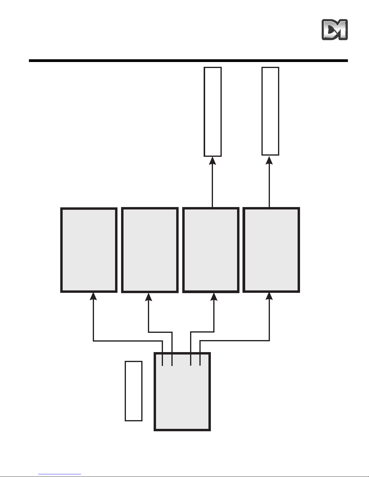
5. MENU FLOW CHART
2040 / 2060 Menu System Manual Page. 27
Main Menu
To Technician Menu
To Supervisor Menu
Go to Preset
Start Tour
Technician Menu
Supervisor
Exit
Preset Numbe
r___
0123456789
Accept Entry
Clear Entry
Return
Tour Numbe
r___
0123456789
Accept Entry
Clear Entry
Return
Enter PI
N____
0123456789
Accept Entry
Clear Entry
Return Without Change
Enter PI
N____
0123456789
Accept Entry
Clear Entry
Return Without Change
Page 30

Supervisor Menu
To Supervisor Menu
Store/Edit Preset
Store/Edit Tour
Alarm Setup
Supervisor Options }
Change PIN
}
Privacy Zone Setup }
Return
Exit
Preset Numbe
r___
0123456789
Accept Entry
Clear Entry
Return Without Change
Delete Preset
Tour Numbe
r___
0123456789
Accept Entry
Clear Entry
Return Without Change
Delete Tour
Alarm Action Setup
Mask Alarms
Select Holidays
Return
Exit
Enter Preset Text -
Yes
No
Alarm Numbe
r___
0123456789
Accept Entry
Clear Entry
Return
Delete Alarm
Item___in
sequenc
e___
PPPDDTT
Old_____
New_____
0123456789
Accept Entry
Clear Entry
Return Without Change
Store Tour
Item___ofAlarm Masks
MTWTFSSHhhmmhhmm
Old_____
New
0123456789
Accept Entry
Clear Entry
Return Without Change
Save and Return
________
_____________
Item___of
Holiday Days
ddmm
Old_____
New
0123456789
Accept Entry
Clear Entry
Return Without Change
Save and Return
________
_____________
ABCDEFGHIJKLMNOPQRSTUVW>
YZabcdefghijklmnopqrstuv
wxyz0123456789:/*=+.-
Backspace
Return Without Change
Accept Entry
________________
Alm___
Select P
or T
Ptnn
Old___
New___
0123456789
Store Alarm
Clear Entry
Return Without Change
(2060 only)
(2060 only)
(2060 only)
(2040 only)
2040 / 2060 Menu System Manual Page. 28
Page 31

Supervisor Options
Digital zoom:
disabled
Bottom flip:
enabled
Freeze frame:
disabled
Set User Timeout: none
Set Date/Time/Language
Preset Text Options
Back
Exit
SSSPT
Old ____
New____
012345689
Accept Entry
Clear Entry
Return Without Changes
Language:
English
Date Format:
dd-mm-yy
Time format:
hh:mm:ss
Set Time and Date
Save and Return
Save and Exit
yymmddhhmm
Old ________
New ________
Accept Entry
Clear Entry
Return Without Change
Preset txt Justify: L
Default Preset txt: on
Edit default Text
Return
Exit
Enter new PI
N___
0123456789
Accept Entry
Clear Entry
Return Without Change
Define single zone
Clear single zone
Define multiple zones
Clear all privacy zones
Return
Exit
Privacy zones
ABCDEFGHIJKLMNOPQRSTUVW>
YZabcdefghijklmnopqrstuv
wxyz0123456789:/*=+.-
Backspace
Return Without Change
Accept Entry
________________
(2060 only)
(2060 only)
2040 / 2060 Menu System Manual Page. 29
Page 32

Technician Menu
Camera set up
Enable/Disable options
Joystick controls
Miscellaneous Services
Change PIN
Return
Exit
Camera colour: col/mono
Preset focus: auto
Near focus:
disabled
Frame integ:
auto
Save and Return
Save and Exit
Activity LED: off
Host polling: on
Video gain:
2
Video lift:
off
Save and Return
Save and Exit
Text edit:
local
Head info disp: disabled
Head info just:
lef
t
Error display:
enabled
Power fail:
P/T/Joy
Save and Return
Save and Exit
Reload Factory Defaults
Clear NVM Errors
Run NVM Check
Return
Exit
Divide by:
16
Linear speed: 5
Pan direction: default
Tilt direction:
Save and Return
Save and Exit
default
Horiz cursor: default
Vert cursor:
default
Host comms/Video amp
Software version
Homing values
Home servos
NVM Services
Reset Head
Return
Exit
Enter new PI
N____
0123456789
Accept Entry
Clear Entry
Return Without Change
2040 / 2060 Menu System Manual Page. 30
Page 33

6. ALTERNATIVE CONTROLLERS
It is possible to control the 2060 and 2040 domes from a wide range of controller devices. Always
refer to the controller manual to identify the correct operating procedures. The following pages
describe the settings and key sequences to control the domes from some of the most common
controllers. However, subsequent changes in controller and keyboard design and operation may
mean that these notes become incorrect.
6.1 Dedicated Micros Digital Sprite 2
6.1.1 Up the coax control
The controller telemetry must be configured as follows:-
Dedicated Micros Alarm and Preset Menu set to BBV Telemetry control.
Dome address switches set to DEN PANEL.
(Refer to the Operation/Installation Manual, supplied with each Dome)
Blue rotary address switch set to F…. Yellow rotary address switch set to D
ST
ORING PRESET POSITIONS:
Note that, in this configuration, it may be quicker to use the DM controller software rather
than using the Dome software.
Move the camera to the desired position then press, and hold, the ‘Preset’ key until “Save preset”
or “Enter preset number” appears on the screen. Enter the preset number using the number keys
and press ‘Enter’. The numbers are entered as normal for presets 1 to 9 but, to access preset 10
enter ‘1’ then ‘10’. Preset numbers 1 – 16 are accessed by entering them as single digits (i.e. ‘1’
then ‘1’ for 11; ‘1’ then ‘6’ for 16).
Preset positions greater than 17 can be programmed using the dome menu. At this stage the preset
menu from the dome will be displayed on the screen enabling you to key in a preset identification.
Text can be entered by moving the cursor under each letter/number in turn using the joystick then
pressing the preset,1, enter keys to accept.
When you have finished entering text, close the menu by moving the cursor down to the Accept edit
line and accept by pressing the ‘preset’, ‘1’, ‘enter’ keys.
On the Digital Sprite there are two enter/accept commands.
1. Press the preset key until “go to position” is shown on the screen then press key 1 then
the enter key i.e. preset,1, enter.
2. Press the preset key until go to position is shown on the screen then key 10 followed by
key 1 i.e. preset,10,1
2040 / 2060 Menu System Manual Page. 31
Page 34

DOME PROGRAMMING:
To access the domse menus, there are two possibilities:
1. For systems set up for 485 control or with Sprite systems dating from mid-2004 onwards,
configured for Dennard/DM C coax control, press the * key twice and a message will
appear on the screen saying, “To enter the menu press enter button”.
2. For older systems using coax control, the following key presses are used:
For the Operator menu press: * 8 8 9 10 10 2
For the Supervisor menu press: * 8 8 9 10 10 3
For the Technician menu press: * 8 8 9 10 10 4
The Operator menu will then be displayed enabling you to navigate around the menus using the
joystick to move the cursor and pressing the ‘enter’ key to accept menu options.
6.1.2 RS485 control
The controller telemetry must be configured as follows:-
Dennard/DM Serial telemetry. This is set up in the System Options menu of the Sprite 2 and then
selected in the Alarms and Presets menu.
Each Dome must be individually addressed
(Refer to the Operation/Installation Manual, supplied with each Dome, for an explanation on access
to, and setting of, the address switches)
RS485 connection from the Sprite 2 is via a 9-way D type female connector and the connection is
as follows: pin 1 = data A =yellow wire from dome
pin 9 = data B =green wire from dome
Domes are, by default, supplied with termination resistors fitted. These will need to be removed
from all but the last dome in the Daisy chain.
6.2 Baxall / Vista controllers
Up the coax control
The controller telemetry must be configured as follows:-
1: Rx attached, needs to be set to DC
2: Telemetry mode, needs to be set to STANDARD
The Dome address switches need to be set to BAX DC PANEL
(Refer to the Operation/Installation Manual, supplied with each Dome, for an explanation on access
to, and setting of, the address switches)
Blue rotary address switch set to F…. Yellow rotary address switch set to E.
2040 / 2060 Menu System Manual Page. 32
Page 35

STORING PRESET POSITIONS:
Note that, in this configuration, it is quicker to use the Baxall controller software rather than
using the Dome software.
To programme a preset via the controller, enable the TELEMETRY, CAMERA and WIPE keys.
Move the camera to the desired position.
Press the function key and enter the preset number using the number keys, then press the preset
key. At this stage the preset menu from the dome will be displayed on the screen enabling you to
key in a preset identification. If you don’t want to add a preset identification, move the cursor down
to the ‘Accept entry’ line and accept by pressing the WASH key. Text can be entered by moving the
cursor under each letter/number in turn, using the joystick, and then pressing the WASH key to
accept.
When you have finished entering text close the menu by moving the cursor down to the ‘Accept
entry’ line and accept by pressing the WASH key. Once the presets have been stored, switch off the
‘CAMERA’ and ‘WIPE’ functions for normal operation.
DOME PROGRAMMING:
Access to the dome menu can be achieved by enabling the TELEMETRY, CAMERA and WIPE
buttons then pressing & holding the preset key, pressing & holding key 6 then release the preset
key then key 6. This will give you access to the operator menu. The Supervisor menu and
Technicians menu can be accessed from this menu. The WASH button is used to enter/accept.
6.3 Dennard/DM dtx1000/dc
Up the coax control
The controller telemetry will output BBV protocols.
The Dome address switches need to be set to DEN PANEL.
(Refer to the Operation/Installation Manual, supplied with each Dome, for an explanation on access
to, and setting of, the address switches)
Blue rotary address switch set to F…. Yellow rotary address switch set to D.
This is the default setting for Dedicated Micros domes unless specified otherwise. If the dome is
supplied with a remote protocol converter in the PSU box, then the address switches will be factory
set to: Yellow = 1 Blue = 0
ST
ORING PRESET POSITIONS:
Notes:
In this configuration, it may be quicker to use the controller software rather than using the
Dome software
The dtx1000 uses on screen menu display which is only available if the monitor is
connected to the keyboard. Simple programming options, like setting a preset position, can
be programmed in without the ability to see the menu display.
2040 / 2060 Menu System Manual Page. 33
Page 36

Move the camera to the desired position.
Press the ‘program’ key (to bring up the menu display), press key No 1 (to select the programme
preset option) then press the number key you want to use to identify the preset. At this stage the
preset menu from the dome will be displayed on the screen enabling you to key in a preset
identification. Text can be entered by moving the cursor under each letter/number in turn using the
joystick then pressing and holding the ‘preset’ key, then pressing key number 1 to accept.
When you have finished entering text, close the menu by moving the cursor down to the ‘Accept
entry’ line and accept by pressing and holding the ‘preset’ key, then pressing key number 1.
DOME PROGRAMMING:
To access the dome menu:
Press and hold the ‘shift’ key then press the ‘wash’ key.
This will give you access to the operator menu. The Supervisor menu and Technicians menu can
be accessed from this point. Holding the ‘preset’ key, then pressing key number 1 is used to
enter/accept.
6.4 Building Block Video TX1000/DC
Up the coax control
The controller telemetry will output BBV protocols
The Dome address switches need to be set to DEN PANEL
(Refer to the Operation/Installation Manual, supplied with each Dome, for an explanation on access
to, and setting of, the address switches)
Blue rotary address switch set to F…. Yellow rotary address switch set to D.
This is the default setting for domes unless specified otherwise.
NB If the dome is supplied with a remote protocol converter in the PSU box, then the
address switches will be factory set to: Yellow = 1 Blue = 0
ST
ORING PRESET POSITIONS:
Notes:
In this configuration, it may be quicker to use the controller software rather than using the
Dome software
The dtx1000 uses on screen menu display which is only available if the monitor is
connected to the keyboard. Simple programming options, like setting a preset position, can
be programmed in without the ability to see the menu display.
Move the camera to the desired position. Press the ‘program’ key (to bring up the menu display),
press key No 1 (to select the programme preset option) then press the number key you want to use
to identify the preset. At this stage the preset menu from the dome will be displayed on the screen
enabling you to key in a preset identification. Text can be entered by moving the cursor under each
letter/number in turn using the joystick then pressing and holding the ‘preset’ key, then pressing key
number 1 to accept.
2040 / 2060 Menu System Manual Page. 34
Page 37

When you have finished entering text close the menu by moving the cursor down to the ‘Accept
entry’ line and accept by pressing and holding the ‘preset’ key, then pressing key number 1.
DOME PROGRAMMING:
To access the dome menu:
Press and hold the # key then press the ‘wash’ key.
This will give you access to the operator menu. The Supervisor menu and Technicians menu can
be accessed from this point. Holding the ‘preset’ key, then pressing key number 1 is used to
enter/accept.
6.5 Dennard/DM dtx400/dc
Up the coax control
The controller telemetry will output BBV protocols
The Dome address switches need to be set to DEN PANEL
(Refer to the Operation/Installation Manual, supplied with each Dome, for an explanation on access
to, and setting of, the address switches)
Blue rotary address switch set to F…. Yellow rotary address switch set to D.
This is the default setting for domes unless specified otherwise.
NB If the dome is supplied with a remote protocol converter in the PSU box, then the
address switches will be factory set to: Yellow = 1 Blue = 0
ST
ORING PRESET POSITIONS:
Note that, in this configuration, it may be quicker to use the Dennard/DM controller software
rather than using the Dome software.
Move the camera to desired position.
Press and hold the ‘Set’ key then press the number key you want to use to identify the preset.
(Note that only eight preset positions can be set using this controller.) At this stage the preset menu
from the dome will be displayed on the screen enabling you to key in a preset identification. If you
don’t want to add a preset identification, move the cursor down to the ‘Accept entry’ line and accept
by pressing key number 1. Text can be entered by moving the cursor under each letter/number in
turn, using the joystick, and then pressing key number 1 to accept.
When you have finished entering text, close the menu by moving the cursor down to the ‘Accept
entry’ line and accept by pressing key number 1.
DOME PROGRAMMING:
To access the dome menu:
Press and hold the ‘shift’ key then press No 1 key
This will give you access to the Operator menu. The Supervisor menu and Technicians menu can
be accessed from this point. The number 1 key is used to enter/accept.
2040 / 2060 Menu System Manual Page. 35
Page 38

6.6 Building Block Video TX400DC
Up the coax control
The controller telemetry will output BBV protocols
The Dome address switches need to be set to DEN PANEL
(Refer to the Operation/Installation Manual, supplied with each Dome, for an explanation on access
to, and setting of, the address switches)
Blue rotary address switch set to F…. Yellow rotary address switch set to D.
This is the default setting for the domes unless specified otherwise.
NB If the dome is supplied with a remote protocol converter in the PSU box, then the
address switches will be factory set to: Yellow = 1 Blue = 0
ST
ORING PRESET POSITIONS:
Note that, in this configuration, it may be quicker to use the Dennard/DM controller software
rather than using the Dome software.
Move the camera to the desired position.
Press and hold the ‘Program’ key then press the number key you want to use to identify the preset.
(Note that only eight preset positions can be set using this controller.) At this stage the preset menu
from the dome will be displayed on the screen enabling you to key in a preset identification. If you
don’t want to add a preset identification, move the cursor down to the ‘Accept entry’ line and accept
by pressing key number 1. Text can be entered by moving the cursor under each letter/number in
turn, using the joystick, and then pressing key number 1 to accept.
When you have finished entering text, close the menu by moving the cursor down to the ‘Accept
entry’ line and accept by pressing key number 1.
DOME PROGRAMMING:
To access the dome menu:
Press and hold the # key then press No 1 key
This will give you access to the Operator menu. The Supervisor menu and Technicians menu can
be accessed from this point. The number 1 key is used to enter/accept
2040 / 2060 Menu System Manual Page. 36
Page 39

7. TROUBLE SHOOTING GUIDE
2040 / 2060 Menu System Manual Page. 37
PROBLEM ACTION
No picture
Check the PSU fuses
Check the input and output voltages
Check all co-ax connections
Continuity check the dome multicore cable:-
Pin 1 =Video
Pin 2 =Video screen
Pin 3 =Data + (Yellow)
Pin 4 =Data(Green)
Pin 5 =24Volt Neutral (blue)
Pin 6 =24Volt Live (red)
Pin = Earth (drain wire)
Picture with no control
If control is via a drx100 protocol converter, check that the Green and
Yellow wires from the dome are connected correctly ie Green to C1
Yellow to C2. Using a video level metre, check the sync pulse is 0.3V
If control is via RS485 check that the data connections are:Green Wire data - Yellow Wire data +
If control is via a 2060 co-ax (which has built in protocol converters),
control is “up the co-ax” but the address switches have to be set to suit
the controller protocol. See the Operation/Installation Manual for
settings.
Picture with intermittent
control
This problem is often due too to much or too little video gain.
If you are using the 2060 co-ax dome with built in protocol converters,
video amplification is accessed through the menu system. Refer to the
manual and adjust the gain to suit.
If you are using a 2060drx as per 2040drx then the Video Gain can be
found on the drx card behind the BNC connectors located in the PSU
box
Flashing cursor size box
top right corner of monitor
This indicates that the Dome software has detected an error. Before
contacting Dennard Technical on 01420 485713 the error display should
be enabled as this will help Dennard Technical to solve your problem.
See section 4.4.2 for details on this.
On Baxall controlled
Domes, alphabet menu
pops up when the joystick
is touched
This may be because the Baxall controller has been configured to
ALTERNATE mode which is not supported by the Dome. Setting the
dome to STANDARD mode with Rx set to DC should solve the
problem.
On Dennard/DM & BBV
controllers the dome
spins continuously
This may be due to the joystick having no ‘dead band’, possibly through
the joystick being off centre on power up. Power the controller down
then power up again ensuring that the joystick is free to self-centre.
(Applicable to 2060 only)
Page 40

Notes
Page 41

MENUSYSTEMVEJLEDNING
Page 42

Page 43

Indhold
1. DEDICATED MICROS TYPE 2060 DOME KAMERA 3
2. DEDICATED MICROS TYPE 2040 DOME KAMERA 5
3. PROGRAMMERBARE FUNKTIONER 7
3.1 Forudindstillede positioner 7
3.2 Forudindstillede positioner 7
3.3 Ture 7
3.4 Realtidsur 7
3.5 Alarmsvar 7
3.6 Bottom Flip 8
3.7 Kamera mode 8
3.8 Digital zoom-udvidelse 8
3.9 Markørindstillinger 8
3.10 Tekstindstillinger 8
3.11 Joystick hastighed 8
3.12 Server afsøgning 8
3.13 Fejlmeddelelse 9
3.14 Aktivitetslys 9
3.15 Bruger timeout 9
3.16 Indstilling af videoforstærkning 9
3.17 Sikkerheds-mode 9
4. BETJENING MED KONTROLPANEL 10
4.1 Dome menu-struktur med Dennard/DM controllere 10
4.2 Hovedmenu 11
4.2.1 Gå til Forudindstillinger eller Start tur 11
4.2.2 Indtastning af PIN-kode 12
4.3 Supervisor menu 15
4.3.1 Gem/Redigér forudindstillinger 15
4.3.2 Gem/Redigér tur 16
4.3.3 Alarmindstillinger 17
2040 / 2060 Menusystemvejledning Side. 1
Page 44

4.3.4 Supervisor indstillinger 19
4.3.5 Indtast ny PIN-kode 22
4.3.6 Sikkerhedszone-indstillinger 22
4.4 Tekniker menu 23
4.4.1 Kameraindstillinger 23
4.4.2 Aktivér/deaktivér indstillinger 24
4.4.3 Joystick kontrol 24
4.4.4 Generel service 25
4.4.5 Indtast ny PIN-kode 26
5. MENU FLOW CHART 27
6. ALTERNATIVE CONTROLLERE 31
6.1 Dedicated Micros Digital Sprite 2 31
6.1.1 Up-the-co-ax kontrol 31
6.1.2 RS485-kontrol 32
6.2 Baxall/Vista controllere 32
6.3 Dennard/DM dtx1000/dc 33
6.4 Building Block Video TX1000/DC 34
6.5 Dennard/DM dtx400/dc 35
6.6 Building Block Video TX400DC 36
7 TROUBLE SHOOTING VEJLEDNING 38
2040 / 2060 Menusystemvejledning Side. 2
Page 45

1. DEDICATED MICROS TYPE 2060 DOME KAMERA
Dette Dedicated Micros 2060 Dome-kamera er en præcisionsenhed med mange muligheder for
valg af variabel hastighed samt en stor hukommelse til lagring af forudindstillede positioner, ture og
alarmsvar. Det er et omskifteligt farve/monokromkamera (kun farvekamera indendørs) med et 18:1
zoomobjektiv samt x 4 digital forstærkning.
Enheden har et stort antal standardfunktioner, der kan tilpasses individuelle ønsker. Der er adgang
til disse via internt genererede menuer, der overlejres videosignalet, hvis controllerens opsætning
ikke er hensigtsmæssig hertil. Dome-kameraet leveres med en seperat vejrbestandig
strømforsyning.
Produktspecifikation:
2040 / 2060 Menusystemvejledning Side. 3
Hastighed 0,05 til 300 º / sekund max. (både pan og tilt)
Gentagelsesnøjagtighed 5 minutters nøjagtighed
Kontrol
RS485 halv dupleks eller simpleks, 9600 Baud ELLER "Up-the-co-ax"
via indbygget DEN PANEL eller BAX PANEL protokolkonverter til
Dennard/DM, BBV og DM eller Baxall controllere
Lagerkapacitet
200 positioner med identificerende titler med indtil 20 tegn,
100 ture med indtil 16 forudindstillinger,
100 alarmsvar.
Strømforsyning
24Va.c, kamera og kontrol elektronik;
-10VA Varme- og blæserenhed:-10VA
Dimensioner
Dome kamera: 150mm diameter halvkugle med 230 mm loftsring
Strømforsyning: 165L x 135B x 95H
Beskyttelse BS EN 60529 til niveau IP66 (ingen indtrængen af vand)
Vægt
Dome kamera: 1,7 kg + monteringsbeslag
Strømforsyning: 1,3 kg
Monteringsløsninger
Beslagtyper: loftsbeslag, hængebeslag, vægbeslag, hjørnebeslag,
snowdrop og pladebeslag
Page 46

18X zoom kameramodul
26X zoom kameramodul
2040 / 2060 Menusystemvejledning Side. 4
Optisk vidde
4,1mm til 73,8mm zoom; F1,4 til F3,0
Autofokus med manuel override
Sikkerhedszoner 24 programmerbare zoner med 8 på skærmen ad gangen
Videofølsomhed 0.7 lux farve
Videoopløsning
768 horisontal x 494 vertikal, pixels
Over 470 TVL
Video output 1,0v p-p composite, negativ synkr
Optisk vidde
3,5mm til 91,0mm zoom; F1,6 til F3,8
Autofokus med manuel override
Sikkerhedszoner 24 programmerbare zoner med 8 på skærmen ad gangen
Videofølsomhed 1.0 lux farve
Videoopløsning
768 horisontal x 494 vertikal, pixels
Over 470 TVL
Video output 1,0v p-p composite, negativ synkr
Page 47

2. DEDICATED MICROS TYPE 2040 DOME KAMERA
Dette Dedicated Micros 2040 Dome-kamera er en præcisionsenhed med mange muligheder for
valg af variabel hastighed samt en stor hukommelse til lagring af forudindstillede positioner,
rotationer og alarmsvar. Det er et farvekamera med et 18:1 zoomobjektiv.
Enheden har et stort antal standardfunktioner, der kan tilpasses individuelle ønsker. Der er adgang
til disse via internt genererede menuer, der overlejres videosignalet, hvis controllerens opsætning
ikke er hensigtsmæssig.
Produktspecifikation:
2040 / 2060 Menusystemvejledning Side. 5
Hastighed 0,05 til 300 º / sekund max. (både pan og tilt)
Gentagelsesnøjagtighed 5 minutters nøjagtighed
Kontrol
RS485 halv dupleks eller simpleks, 9600 Baud ELLER "Up-the-co-ax"
via indbygget DEN PANEL eller BAX PANEL protokolkonverter til
Dennard/DM, BBV og DM eller Baxall controllere
Lagerkapacitet
100 positioner med identificerende titler med indtil 20 tegn
50 rotationer med indtil 16 forudindstillede positioner
50 alarmsvar
Strømforsyning 24Va.c, kamera og kontrol elektronik; 10VA
Dimensioner
150mm diameter halvkugle med 220 mm loftsring
110mm højde bagved loftspanelet
Vægt 1,5 kg
Monteringsløsninger Plademontering
Page 48

18X zoom kamera
2040 / 2060 Menusystemvejledning Side. 6
Optisk vidde
4.1mm til 73.8mm optisk zoom; F1.4 til F3.0
Autofokus med manuel override
Sikkerhedszoner 24 programmerbare zoner med 8 på skærmen ad gangen
Videofølsomhed 3 lux farve
Videoopløsning
768 horisontal x 494 vertikal, pixels
Over 470 TVL
Video output 1,0v p-p composite, negativ synkr
Page 49

3. PROGRAMMERBARE FUNKTIONER
Dedicated Micros 2060/2040 Dome-kamera har en række funktioner, der kan vælges af
supervisoren, når domen er blevet installeret. Disse kan alle efterfølgende ændres eller helt slettes
med henblik på at optimere systemets operationsdygtighed. De kaldes frem eller annulleres via
skærmmenu-strukturer som beskrevet i afsnit 4 og indstillingerne gemmes i non-volatil
hukommelse, således at de ikke berøres af strømsvigt.
Funktionerne er beskrevet herunder:
3.1 Forudindstillede positioner
Der kan gemmes og genkaldes indtil 200 (2060) eller 100 (2040) positioner til enhver tid. Hver
position gemmer pan-, tilt-, zoom- og fokus- positionerne såvel som positionernes titel.
3.2 Forudindstillede positionstitler
En forudindstillet titel kan have indtil 20 alfanumeriske tegn til særskilt identificering af den
pågældende position. Standardtitlen er placeret i videobilledets prima venstre hjørne,
venstrejusteret, men denne placering kan ændres, hvis dette ønskes.
De forudindstillede titler viser sig kun ved selve positionen. Ved en bevægelse væk fra positionen,
er disse ikke længere synlige.
3.3 Ture
Der kan gemmes og genkaldes indtil 200 (2060) eller 100 (2040) rotationer til enhver tid. En tur kan
indeholde op til 16 positioner heri indbefattet en programmeret forsinkelse (dwell time) ved hver
position samt domens rejsetid frem til næste position. Når domen er nået frem til den sidste
position, returnerer turen i en "sløjfe" til oprindelig position.
3.4 Realtidsur (ikke anvendelig på den 2040)
Der er indbygget et realtidsur i 2060 dome-kameraet, hvilket giver mulighed for at indstille tids- og
datomarkeringer for brugeren og optagesystemet, hvis dette ønskes. Der kan vælges mellem et
udvalg af formater til visning af tid og dato, og enheden kan gøre brug af disse oplysninger til at
forbedre alarmfunktionerne, der således kan ændres alt afhængig af tidspunkt og ugedag.
3.5 Alarmsvar
Der kan lagres indtil 100 (2060) eller 50 (2040) alarmsvar. Et alarmsvar fremkalder en bestemt
reaktion via et alarmnummer. Dette er en meget effektiv funktion, idet et antal dome, eller enhver
anden enhed, der er tilpasset Dennard/DM-protokollen, således kan fremkalde en forudindstillet
alarmreaktion via en enkelt sløjfetransmitteret kommando.
2040 / 2060 Menusystemvejledning Side. 7
Page 50

3.6 Bottom Flip
Domen vil automatisk foretage en 180opan-bevægelse så hurtigt som muligt, når det tiltes helt ned,
således at det er muligt at følge en person eller bil, der bevæger sig direkte under domen, idet
joysticket kun skal bevæges i én retning.
3.7 Kamera mode
Kameraet – både 2060 og 2040-modellen – kan indstilles til farve eller monokrom mode. I 2060
kameraet kan der vælges farve/mono, hvorefter det automatisk skifter til mono, når lysniveauet er
for lavt til at optage farvebilleder af god kvalitet.
3.8 Digital zoom-udvidelse
Kamerasystemet giver mulighed for udvidelse af zoomobjektiv. Dette sker ved en yderligere
udvidelse af billedets centrale del til at udfylde skærmbilledet. Denne funktion kan vælges.
3.9 Markørindstillinger
Selve menu-strukturen og de tilgængelige valgmuligheder kan søges og aktiveres ved en enkelt
markør eller et blinkende tegn og markørens bevægelsesretning afhænger af det kontrolpanel, der
benyttes. Bevægelsesretningen kan reverseres separat for horisontal og vertikal bevægelse, hvis
dette ønskes.
3.10 Tekstindstillinger
Al tekst kan placeres, hvor den ønskes, erstattes med standardtekst (f.eks.: Position 31, eller
Sektor 18), eller eventuelt fjernes, hvis dette ønskes.
3.11 Joystick hastighed
Selv om kontrolpanelet har et joystick med stor proportional hastighed, er Dedicated Micros
domens hastighedsinterval så stort, at der er behov for både et lavt og et højt hastighedsinterval,
hvis systemet skal virke optimalt (selvfølgelig under forudsætning af, at kontrolpanelet kan aktivere
disse individuelt).
Det lave hastighedsinterval er ganske enkelt lig med det høje hastighedsinterval og følger den
samme indbyggede korrelationslov blot delt med en konstant. Denne konstant kan indstilles til
mellem 2 og 128.
3.12 Server afsøgning
Når en dome er konfigureret til kommunikation via en RS485-protokol, kan den indstilles til at
kontrollere kommunikationsforbindelsen med regelmæssige mellemrum. Hvis der ventes en
kontinuerlig datastrøm fra controlleren, vil domen ved aktivering af server afsøgning sende
meddelelse om en kommunikationsfejl, hvis der ikke modtages noget input inden for 5 sekunder.
Denne indstilling er normalt deaktiveret.
2040 / 2060 Menusystemvejledning Side. 8
Page 51

3.13 Fejlmeddelelse
Dedicated Micros domen overvåger selv konstant systemets tilstand og kan indikere, at der er
opstået en fejl ved hjælp af en blinkende firkant i det øverste højre hjørne af det transmitterede
billede. Det er efterfølgende muligt at spørge om årsagen. Som en anden mulighed kan enheden
vise fejlmeddelelsesteksten i stedet for den blinkende firkant.
3.14 Aktivitetslys
En grøn lysdiode (LED) yder hjælp til fejldianogstik, når domen sættes i gang, og den lyser også,
når kommando-signaler modtages. Da den kan være synlig udefra, kan den slås til og fra.
3.15 Bruger timeout
Det kan ikke udelukkes, at domen bliver efterladt i en uhensigtsmæssig position og af en aller
anden grund herefter "glemt". For at afbøde denne risiko er der i systemet to indstillinger til hindring
heraf. Disse er Forudindstilling 001 og Tur 001.
Der kan indstilles en tidsforsinkelse på mellem 1 og 999 sekunder og en forudbestemt reaktion efter
timeout kan ligeledes defineres. Hvis tidspunktet er overskredet efter joystick/indtastning pan og tilt
input i kontrolpanelet, vil den forudindstillede handling sættes i gang.
Hvis den forudindstillede tidsforsinkelse er indstillet til 0, bliver der ikke igangsat nogen
forudbestemt handling og enheden vil afvente bruger input på ubestemt tid.
Hvis dome-menuen ikke modtager input inden for 3 minutter, går systemet i dvale (timeout), og
domen genoptager sin tidligere aktivitet.
3.16 Indstilling af videoforstærkning (video gain)
Denne funktion gør det muligt at justere videoforstærkningens standardindstilling. Der er 4
indstillingsniveauer. Vertikal videobevægelse (video lift) kan slås til og fra og er normalt slået fra i
standardindstillingen.
3.17 Sikkerheds-mode
Det kan til tider være ønskeligt at hindre brugere i at se bestemte områder. For at imødekomme
dette behov er det i sikkerheds-mode muligt at få disse områder dækket med sorte felter.
Det overlejrede felts størrelse afhænger af monitorbilledet ved den anvendte zoom-indstilling. Når
der zoomes ud, reduceres feltets størrelse, således at det kun dækker det oprindelige område.
2040 / 2060 Menusystemvejledning Side. 9
Page 52

4. BETJENING MED KONTROLPANEL
NB: Denne er forskellig alt afhængig af kontrolpanel. Der henvises til controllervejledningen.
Dome-kameraet er en åben kontrolenhed. Således kan kameraet drives via forskellige controllere.
Alle domens mange funktioner programmeres via en af tre menu-strukturer. Hver controller har
særlige kontrolfigurationer, hvilket nødvendiggør, at brugeren læser controller-vejledningen for at
vurdere, hvilken knap, der skal bruges til at få adgang til menu-funktionerne. I afsnit 6 beskrives
disse funktioner for flere af de mest almindelige controllere.
De følgende instruktioner giver vejledning i menu-strukturens opbygning for Dome med
strømforsyning (med adresse indstillet til No. 253… DEN PANEL), styret af en Dennard/DM
dtx400dc eller dtx1000dc.
4.1 Dome menu-struktur med Dennard/DM controllere
Menuerne fremkommer på skærmen ved aktivering af en af de følgende kommandoer:
Bemærk, at "shift"tasten skal holdes nede, når valget foretages.
Ved aktivering fremkommer menuen på monitorskærmen med det normale videoskærmbillede i
baggrunden og med markøren i venstre kant. Valg foretages ved at positionere markøren på den
ønskede funktion, hvorefter der trykkes på "ACCEPT"-knap(perne), der for Dennard/DM controllere
er således:
For dtx1000dc, hold forudindstillings-knappen nede og tryk på KAMERA VALG 1
For dtx 400dc, tryk på forudindstilling 1-knappen
2040 / 2060 Menusystemvejledning Side. 10
dtx1000dc adgang dtx400dc adgang
Brugermenu shift wash shift 1
Supervisor menu (der kræves adgangskode) shift wipe shift 2
Tekniker menu (der kræves adgangskode) shift autopan shift 3
Page 53

4.2 Hovedmenu
Når hovedmenuen kaldes frem, vises der et skærmbillede med følgende valgmuligheder, med et
kameraskærmbillede om baggrund og med en markør i venstre kant.
Ved hjælp af joysticket eller piletasterne køres op eller ned i listen for at vælge ønsket funktion,
hvorefter funktionen accepteres/vælges ved tryk på de(n) pågældende tast(er). Hvis "Afslut"
vælges, nulstilles menuen og domen foretager ikke yderlige handlinger.
4.2.1 Gå til Forudindstillinger eller Start tur
Det er her muligt for brugeren at genkalde alle gemte forudindstillede positioner og ture, også selv
om kontrolpanelet hverken har det numeriske interval eller er generelt indstillet hertil.
Bemærk, at der kun er adgang til eksisterende forudindstillede positioner og ture via dette
skærmbillede. I afsnit 4.3.1/4.3.2 beskrives processen omkring indstilling af nye positioner
eller ture
Der vil nu blive forespurgt om den numeriske indtastningsværdi via følgende undermenu:
Markøren kan flyttes hen over talrækken ved hjælp af joysticket eller kontrol-knapperne hen til det
ønskede tal. Tegnene vil herefter blinke, og så snart et tal er valgt ved tryk på ACCEPTknap(perne), vil det vises i _ _ _ delen af skærmen.
Det er ikke nødvendigt at indtaste initiale nuller (f.eks. kan 001 blot indtastes som "1"), men
indtastningen skal ligge inden for grænsen, f.eks. 001 – 250 for forudindstillinger og 001 – 100 for
rotationer (2060) og 001 – 100 for forudindstillinger og 001 – 50 for rotationer (2040). Hvis den
indtastede talværdi ligger uden for dette interval, vil meddelelsen "Ulovlig indtastning" blinke og
indtastningen må nulstilles og gentages.
Når tallene er valgt, vil valget blive implementeret via "Acceptér indtastning" og skærmen vil
automatisk ændres til den ønskede kameraposition.
2040 / 2060 Menusystemvejledning Side. 11
Gå til forudindstillinger
Start tur
Tekniker menu
Supervisor menu
Afslut
Forudindstillingsnummer___ (eller tur nummer)
0123456789
Acceptér indtastning
Nulstil indtastning
Retur
Page 54

Valget kan ændres ved tryk på "Nulstil indtastning", hvorved processen genstarter.
Bemærk, at Forudindstilling 1 og Tur 1 bør tildeles de hyppigste og vigtigste visninger.
Domen returnerer automatisk til disse indstillinger i tilfælde af strømsvigt, hvis der ikke er
noget operatør input. Der henvises til afsnit 4.4.2 om strømsvigt.
4.2.2 Indtastning af PIN-kode
Når Tekniker eller Supervisor menu kaldes frem, fremkommer følgende skærm. Adgangskoden
eller PIN-koden indtastes ved brug af de samme metoder, som blev benyttet ved de tidligere
indtastninger.
Markøren kan flyttes hen over talrækken ved hjælp af joysticket eller kontrol-knapperne hen til det
ønskede tal. Tegnene vil herefter blinke, og så snart et tal er valgt ved tryk på ACCEPTknap(perne), vil det vises i _ _ _ delen af skærmen.
Når alle fire tal er valgt, vil valget blive implementeret via "Acceptér indtastning" og skærmen vil
automatisk ændres til den valgte menu, dvs. Tekniker eller Supervisor menu.
2040 / 2060 Menusystemvejledning Side. 12
IndtastPIN____
0123456789
Acceptér indtastning
Nulstil indtastning
Annullér
Page 55

DE FABRIKSINDSTILLEDE ADGANGSKODER (PIN-koder), DER
KAN ÆNDRES AF TEKNIKEREN ELLER SUPERVISOREN I DE
RESPEKTIVE MENUER, ER GENGIVET NEDENFOR.
FOR AT HINDRE, AT DER FORETAGES UAUTORISEREDE
ÆNDRINGER AF INDSTILLINGERNE ELLER LAGREDE
KAMERAPOSITIONER, ANBEFALES DET, AT PIN-KODERNE
OPBEVARES FORSVARLIGT.
HVIS DET FINDES NØDVENDIGT, KAN DENNE SIDE RIVES UD
AF VEJLEDNINGEN
2040 / 2060 Menusystemvejledning Side. 13
Adgangskoden til Supervisor menu er "1111".
Adgangskoden til Tekniker menu er "9999".
Page 56

2040 / 2060 Menusystemvejledning Side. 14
Page 57

4.3 Supervisor menu
SUPERVISOR MENUEN giver supervisor mulighed for duplikering af Tekniker menu-funktionerne
samt programmering af forudindstillede positioner (med identificerende titler) og ture. Derudover er
der via denne menu adgang til markør-indstillinger og placering af tekst.
Funktionerne er tilgængelige i en række underliggende menuer. Når man returnere af en
underliggende menu, returnerer man i de fleste tilfælde til den overliggende menu. De funktioner,
der almindeligvis kun bruges sjældent, ligger dybere i strukturen.
I Supervisor menu er følgende valgmuligheder tilgængelige:
4.3.1 Gem/Redigér forudindstillinger
Første valgmulighed giver supervisor mulighed for at definere et skærmbillede (herunder pan-, tiltog zoom-indstillinger) og gemme det til senere fremkaldelse. Bemærk, at en forudindstilling kun kan
gemmes, hvis det ønskede kamerabillede er synligt, når man går ind på skærmbilledet. Ved valg af
denne indstilling fremkommer følgende underliggende skærmbilleder.
Forudindstillingsnummer vælges på samme måde som ved de tidligere beskrevne skærmbilleder
med numerisk indtastning. Når tallet er accepteret, vil et nyt skærmbillede give supervisor mulighed
for at navngive positionen (f.eks. "Hovedindgang" eller "Hoveddør") eller bruge de standard navne,
der er gemt i dome-softwaren. Skærmbilledet vil vise sig med følgende prompt:
Redigér forudindstillet tekst-
Ja
Nej
Forudindstillingsnummer___
0123456789
Acceptér indtastning
Nulstil indtastning
Retur uden ændring
Slet forudindstilling
Gem/Redigér forudindstillinger
Gem/Redigér tur
Alarmindstillinger
Supervisor indstillinger
Ændring af PIN
Sikkerhedszone-indstillinger
Retur
Afslut
2040 / 2060 Menusystemvejledning Side. 15
Page 58

Vælg "Nej" for at bruge standard navne eller "Ja" for at indtaste et nyt navn via den følgende
skærm.
Titlen vælges som hidtil beskrevet med markøren og accepteres, når den er indtastet (den valgte
titel gemmes herefter sammen med den forudindstillede position). Ved Ryk tilbage kan der
foretages rettelser, hvorimod den forudindstillede position vil blive gemt sammen med standardtitlen
ved valg af "Retur uden ændring". Titlen viser sig i _ _ feltet, når den er blevet kompileret.
Bemærk at de _ vist her kun angiver, hvor dette sker - de vises ikke på skærmen.
4.3.2 Gem/Redigér tur
En tur defineres som en forudbestemt rejse, som kameraet skal foretage mellem en række
forudindstillede positioner. Inden man går ind i denne funktion, bør det sikres, at de ønskede
forudindstillede positioner er blevet gemt som angivet i afsnit 4.3.1.
Inden en tur kan programmeres, skal der først indtastes et tur nummer på samme måde som for
valg af position (dog skal tallet ligge inden for intervallet 001 - 100). Når tallet er blevet accepteret,
vises en undermenu:
Hvis der allerede er indstillet en tur med samme nummer, vises oprindelig dataindtastning som
"Gammel". Disse data kan redigeres ved tilføjelse af nye værdier, eller en ny tur kan indstilles.
Indtastningsformatet er det samme som hidtil beskrevet, men _ _ _ tegnene har særlige funktioner.
De første tre tegn, PPP, står for et forudindstillet positionsnummer. "DD" er den programmerede
forsinkelse (dwell), hvor kameraet hviler ved positionen, og "SS" repræsenterer det tidsrum,
kameraet skal bruge til at nå frem til næste position i turen.
Tiderne indtastes i sekunder mellem 01 - 99. Hvis der ikke indtastes nogen værdi, vil den standard
programmerede hviletid være 2 sekunder og rejsetiden 3 sekunder..
2040 / 2060 Menusystemvejledning Side. 16
ABCDEFGHIJKLMNOPQRSTUVWX
YZabcdefghijklmnopqrstuv
wxyz0123456789:/*=+.-
Ryk tilbage
Retur uden ændring
Acceptér indtastning
____________
Punkt___itur ___
PPPDDTT
Gammel_______
Ny_______
0123456789
Acceptér indtastning
Nulstil indtastning
Retur uden ændring
Gem tur
Page 59

Når alle tegn er indtastet og accepteret, ryddes indtastningsfeltet og systemet er klar til at modtage
oplysninger om den næste position og "Punkt"-tælleren forhøjes. Når alle indtastninger er foretaget,
vælges "Gem tur"-kommandoen.
4.3.3 Alarmindstillinger
Alarmer er input til domen, der aktiverer domen til at foretage en bestemt handling. De kan hidrøre
fra en række eksterne kilder såsom døralarmer eller PIR bevægelsesfølere. I 2060-Domen er der
indbygget et realtidsur, der gør det muligt for supervisor at vælge mellem forskellige alarmreaktioner
alt afhængig af tidspunkt og ugedag. Denne funktion er ikke tilgængelig i 2040-modellen. Gå videre
til afsnit 4.3.3.1. Via skærmbilledet for alarmindstillinger er der adgang til tre valgmuligheder:
4.3.3.1 Forudindstilling af alarmhandlinger
Inden programmering af denne funktion skal supervisor først vælge et alarmnummer som hidtil
beskrevet, hvorefter følgende skærmbillede fremkommer:
Ved accept af alarmnummer fremkommer følgende skærmbillede:
Herved gemmes en foruddefineret position P eller tur T sammen med identificeringsnummeret
"nnn", der implementeres, når alarmen aktiveres. Indstilling vælges ved indtastning af kode "01" for
tur eller "10" for forudindstilling af position (ettallet under P eller T angiver dets formål; 11 er
ugyldigt). Ved accept af indtastningen forhøjes alarm-antallet, idet der enten knyttes en handling til
alle nye input eller de allerede indstillede handlinger knyttet til input - nu angivet som "Gammel" ændres. Alarmindstillingen opretholdes i det tidsrum, der er indstillet via Bruger timeout (se afsnit
4.3.4.1).
2040 / 2060 Menusystemvejledning Side. 17
Forudindstilling af alarmhandlinger
Maske alarmer
Vælg helligdage
Retur
Afslut
Alarmnummer ___
01234567890
Acceptér indtastning
Nulstil indtastning
Retur uden ændring
Slet alarm
Alm___Vælg P eller T
Ptnnn
Gammel____
Ny____
0123456789
Acceptér indtastning
Nulstil indtastning
Retur uden ændring
(Dette skærmbillede er ikke tilgængeligt for
2040-modellen.)
Page 60

4.3.3.2 Maske alarmer (Dette skærmbillede er ikke tilgængeligt for 2040-modellen.)
Alarmsvar kan ændres afhængigt af, hvornår de er blevet aktiveret. Ved valg af denne funktion
fremkommer følgende skærmbillede:
De viste bogstaver står for:
MTOTFLS Mandag til søndag
H Helligdag
ttmm Tidspunkt for "Maske aktiveret"
ttmm Tidspunkt for "Maske" deaktiveret"
Ved indtastning af "1" under ugedag maskes alarmerne - dvs. at de ikke udløser en reaktion fra
domen - den dag. På samme måde betyder et "1" under Helligdag, at alarmen er masket på
foruddefinerede helligdage (Bemærk, at indstillingen for en helligdag tilsidesætter indstillingen for
en ugedag). Masken vil være aktiveret de valgte dag, med mindre der er indtastet tidspunkter for
aktivering og deaktivering. Dette gøres via numerisk indtastning af tidspunkter i et 24 timers døgn.
Masken deaktiverer midlertidigt alle forbundne alarmer.
Hvis bevægelsesfølerne f.eks. er blevet tilsluttet domen og kun er indstillet til at fungere uden for
normal arbejdstid, kan de maskes ved indtastning af koden "1111100008301800". Herved maskes
alarmen fra mandag til fredag mellem 8.30 og 18.00. Uden for dette tidsrum og efter weekender og
helligdage reagerer domen på alarmerne som ønsket.
For at optimere systemets fleksibilitet er der indtil ti tilgængelige konfigureringsniveaer, angivet ved
"punkt nummeret" på skærmen. Efterhånden som hver indtastning accepteres, forhøjes antallet,
indtil hele handlingen gemmes. Via sekundære niveauer er det mulighed for at vælge forskellige
masketider på forskellige dage. I ovennævnte eksempel kan det være, at der lukkes ned tidligt om
fredagen. Til indstilling af forskellige tidspunkter skal den første kode (punkt) ændres til
"1111000008301800" og den anden kode indtastes som "0000100008301400". Nu er masken kun
aktiveret fra mandag til torsdag, mens det sekundære niveau masker alarmerne på fredage mellem
8.30 og 14.00. Mere komplicerede masker kan konstrueres ved brug af samme logik i flere
variationer.
4.3.3.3 Vælg helligdage (Dette skærmbillede er ikke tilgængeligt for 2040-modellen.)
Der kan forprogrammeres indtil 15 helligdage til dækning af perioder som f.eks. jul og helligdage,
hvor indstilling af alarmhandlingen muligvis skal ændres. Når denne mulighed er valgt, vises
følgende skærmbillede:
2040 / 2060 Menusystemvejledning Side. 18
Punkt___ialarm maske
MTOTFLSHttmmttmm
Gammel______________
Ny____
0123456789
Acceptér indtastning
Nulstil indtastning
Retur uden ændring
Gem og retur
__________
Page 61

Datoer kan nu indtastes (f.eks. 2512 for juledag) til indstilling af årets helligdage. Ved accept af hver
indtastning promptes for næste indtastning. Vælg "Gem og retur", når indtastningen er afsluttet.
Bemærk, at nogle datoer, som f.eks. helligdage, eventuelt skal ændres ved starten af et nyt
år.
4.3.4 Supervisor indstillinger
En række funktioner er grupperet under kategorien Supervisor indstillinger. De fleste af disse
ændrer måden, hvorpå tekst og informationer præsenteres for brugeren, men nogle
kameraindstillinger kan ændres med henblik på tilpasning til installationskravene. Ved valg af denne
menu fremkommer følgende skærmbillede:
De første tre valgmuligheder relaterer til kamerafunktioner og er alle indstillet på samme måde.
Indstillingen ændres ved at bevæge markøren op/ned, indtil den er placeret ved siden af
funktionen. Ved bevægelse af joysticket mod venstre eller højre (eller ved tryk på venstre/højre
piletast) rulles igennem forskellige indstillinger. Ved bevægelse op og ned fastsættes værdien på
skærmen. Hvis digital zoom er aktiveret, vil funktionen blive automatisk kaldt frem af kameraet, når
zoom kontrol holdes inde, efter at optisk zoom har nået sit mekaniske ydrepunkt. Via skærmbilledet
i 2040-modellen har supervisor mulighed for at vælge sprog på samme måde. Digital zoomindstillingerne gemmes sammen med eventuelt forudindstillede positioner, men hvis digital zoom
deaktiveres på et senere tidspunkt, vil de forudindstillede, fremkaldte positioner returnere positionen
med optisk zoom fuldt udvidet.
Bottom flip-funktionen kan bruges til at spore objekter, der bevæger sig direkte under domen. Hvis
funktionen er deaktiveret, kan kamerabilledet bevæges nedad, indtil det kigger direkte under
domen, men forbliver i denne position. Hvis funktionen er aktiveret, vil kameraet automatisk rotere
180o, således at operatøren får mulighed for at spore objektet, mens det bevæger sig bort fra
domen.
2040 / 2060 Menusystemvejledning Side. 19
Punkt___helligdage
ddmm
Gammel____
Ny____
0123456789
Acceptér indtastning
Nulstil indtastning
Retur uden ændring
Gem og retur
Digital zoom: uarbejdsdygtig
Bottom flip: aktiveret
Frys billede:
Indstil Bruger timeout: intet
Indstil dato/tid/sprog
Forudindstil tekstindstillinger
Retur
Afslut
uarbejdsdygtig
(Dette skærmbillede er ikke tilgængeligt for
2040-modellen.)
Page 62

Ved Frys billede-funktionen fastholdes det sidste billede på skærmen, mens domen bevæger sig
med fuld hastighed hen til en forudindstillet position. Når domen er nået frem, vises det normale
billede. Herved undgås et sløret billede, mens domen bevæger sig med stor hastighed til
forudindstillede positioner.
4.3.4.1 Indstil bruger timeout
Bruger timeout-funktionen kan bruges til at indstille domens reaktion, hvis der ikke kommer
operatør input. Ved valg af denne funktion fremkommer følgende skærmbillede:
Systemet giver mulighed for at indstille standard timeout i intervallet 1 til 999 sekunder indtastet
som "SSS". Dette er tidsrummet fra sidste joystick (eller P/T-taster) input fra brugeren og en
automatisk bevægelse hentil standard turens udgangspunkt eller til standard positionen, forudsat at
disse er blevet programmeret. Værdien for "PT" angiver, hvilken handling der skal foretages. Ved
indtastning af kode 01 vælges tur og ved indtastning af kode 10 vælges den forudindstillede
position (11 er en ulovlig indtastning).
Ved valg af denne funktion fremkommer følgende skærmbillede Ved accept af indtastningen bliver
supervisoren ført tilbage til valgmulighederne og det valgte tidspunkt vil fremgå af skærmen. Hvis
timeout er indstillet til 0, vil dette fremgå af skærmen med beskeden "Intet" og enheden vil afvente
operatør input på ubestemt tid.
4.3.4.2 Indstil dato/tid/sprog (Dette skærmbillede er ikke tilgængeligt for 2040-modellen.)
2060 Domen har et realtidsur, der skal sættes op ved montering. Enheden indeholder også andre
valgmuligheder m.h.t. sprog og muligheden for at vælge og ændre format til visning af tid.
Alle tre funktioner er indstillet på samme måde. Indstillingen ændres ved at bevæge markøren
op/ned, indtil den er placeret ved siden af funktionen. Ved bevægelse af joysticket mod venstre eller
højre (eller ved tryk på venstre/højre piletast) rulles igennem forskellige indstillinger. Ved bevægelse
op og ned fastsættes værdien på skærmen.
2040 / 2060 Menusystemvejledning Side. 20
SSSPT
Gammel____
Ny____
0123456789
Acceptér indtastning
Nulstil indtastning
Retur uden ændring
Sprog: Engelsk
Datoformat dd-Mmm-åå
Tidsformat tt:mm:ss
Indstil starttid og dato
Gem og retur
Gem og afslut
Page 63

Tids- og datoformatet afgør, hvorledes det normale brugerskærmbillede viser tid og dato. Der er
adgang til mange tilgængelige formater via rullemenuen og det er også muligt at deaktivere tids- og
datovisning, hvis dette ønskes.
Ved indstilling af tid og dato fremkommer følgende skærmbillede:
Via den numeriske indtastning kan dags dato og tidspunkt indtastes, eller de eksisterende værdier
kan lades uændrede.
4.3.4.3 Forudindstil tekstindstillinger
De betegnelser, der er blevet tildelt de forudindstillede kameravisninger, kan angives individuelt,
eller der kan tildeles en standardbetegnelse. Standardbetegnelsen er forprogrammeret som
"Position", men denne kan ændres, hvis dette ønskes, via denne funktion. Placeringen af
betegnelsen på skærmen kan ligeledes justeres. Det følgende skærmbillede fremkommer:
Den forudindstillede betegnelse kan vises i skærmens venstre eller højre side, eller visningen kan
deaktiveres ved at vælge den pågældende funktion og rykke til venstre og højre for at justere
værdien. Hvis standardbetegnelsen skal ændres, vælges Redigér-funktionen, hvorefter det virtuelle
tastatur til indtastning vil blive tilgængeligt.
Betegnelsen vælges som hidtil beskrevet med markøren og accepteres, når den er indtastet (den
valgte betegnelse gemmes herefter som standardbetegnelsen). Ved valg af Ryk tilbage kan der
foretages ændringer og ved valg af "Retur uden ændring" ændres standardbetegnelsen ikke.
2040 / 2060 Menusystemvejledning Side. 21
ååmmddttmm
Gammel_______
Ny_______
0123456789
Acceptér indtastning
Nulstil indtastning
Retur uden ændring
Forudindstil tekstjustering: V
Forudindstillet standardtekst: Aktiveret
Redigér standardtekst
Retur
Afslut
ABCDEFGHIJKLMNOPQRSTUVWX
YZabcdefghijklmnopqrstuv
wxyz0123456789:/*=+.-
Ryk tilbage
Retur uden ændring
Acceptér indtastning
____________
Page 64

Bemærk, at de _ , der er vist her, kun angiver, hvor dette sker - de vises ikke på skærmen.
4.3.5 Indtast ny PIN-kode
Supervisorens PIN-kode er forprogrammeret, men den kan ændres af supervisoren via følgende
skærmbillede:
Indtast den nye PIN-kode (adgangskode) og acceptér indtastningen.
Notér den nye PIN-kode og gem den et sikkert sted.
4.3.6 Sikkerhedszone-indstillinger
Via den sidste valgmulighed i Supervisor menu gives der mulighed for, at særlige områder inden for
kameraets synsfelt blankes ud, således at brugeren ikke kan overvåge eller gemme billeder fra
disse områder. Inden denne funktion vælges, skal det sikres, at kameraet er positioneret, således
at det pågældende område, der skal blankes ud, vises i fuldt skærmbillede på monitoren. Følgende
valg er herefter tilgængelige:
Ved valg af "Definér enkelt zone" går skærmen i sort, når feltet indsættes. Idet domen er gået
tilbage i normal mode, uden for skærmindstillingerne, flyt kameravisningen væk fra området og det
sorte felt forbliver i stilling.
Ved definering af flere zoner vil skærmen blive sort og teksten "Sikkerhedszoner" vises på
skærmen. Flyt kameraet til det ønskede område og tryk på "Enter" for hver zone. Når dette er gjort,
gå ind i menu-strukturen via tastsekvensen (f.eks. #1 for dtx400) for at gå bort fra funktionen.
Inden nulstilling af en sikkerhedszone skal kameraet være positioneret over zonen, inden "Nulstil"funktionen eller "Nulstil alle sikkerhedszoner" vælges. Domen vil straks gå tilbage i normal drift,
efter at zonen/zonerne er blevet slettet.
2040 / 2060 Menusystemvejledning Side. 22
IndtastPIN____
0123456789
Acceptér indtastning
Nulstil indtastning
Annullér
Definér enkelt zone
Nulstil enkelt zone
Definér flere zoner
Nulstil alle sikkerhedszoner
Retur
Afslut
Page 65

4.4 Tekniker menu
Via Tekniker menuen er der adgang til en række funktioner, der fastlægger domens generelle
betjeningskonfigureringer. Denne menu bruges kun sjældent, efter at domen er blevet installeret og
gjort driftsklar.
Når menuen kaldes fremvises følgende skærmbillede:
4.4.1 Kameraindstillinger
Der kan foretages en række ændringer i domen af kamera-modulets funktion. Det følgende
skærmbillede bruges:
Alle funktioner er indstillet på samme måde. Indstillingen ændres ved at bevæge markøren op/ned,
indtil den er placeret ved siden af funktionen. Ved bevægelse af joysticket mod venstre eller højre
(eller ved tryk på venstre/højre piletast) rulles igennem forskellige indstillinger. Ved bevægelse op
og ned fastsættes værdien på skærmen. Ved valg af farve/mono opererer kameraet i farve mode,
indtil lysniveauet kommer under et forudbestemt niveau, hvorefter det automatisk skifter til mono
mode. Det modsatte vil ske, når lyset vender tilbage til et passende niveau for farve mode.
Kameraet kan også indstilles fast i farve eller mono mode, hvis dette ønskes.
Når en forudindstilling gemmes, gemmes objektivets fokus-position ligeledes. Hvis det
forudindstillede fokus er indstillet til "auto" (den foretrukne indstilling), vil kameraet selv refokusere,
således at det indstilles til ændrede forhold. Ved indstilling af fokus til manual påtvinges kameraet
den oprindelige fokus-indstilling, mens det forbliver i den forudindstillede position.
Makro-indstillingen kan benyttes indendørs, idet det gør det muligt for kameraet at fokusere på
objekter, der er under en meter væk. Denne indstilling bør deaktiveres for almindelig udendørsdrift,
idet den ellers vil fokusere på regndråber, der falder ned på halvkuglen. Hvis billedintegrationen er
indstillet til "auto", er kameraet i stand til at tilpasse billedhastigheden til svag belysning. Hvis
"normal" vælges, vil billedhastigheden bevares, men billedkvaliteten forringes muligvis ved svag
belysning.
2040 / 2060 Menusystemvejledning Side. 23
Kameraindstillinger
Aktivér/deaktivér indstillinger
Joystick kontrol
Generel service
Ændring af PIN
Retur
Afslut
Kamerafarve: farve/mono
Forudindstil fokus: auto
Makro-fokus: deaktiveret
Billedinteg: auto
Gem og retur
Gem og afslut
Page 66

4.4.2 Aktivér/deaktivér indstillinger
Der er en række tilgængelige funktioner, der giver teknikeren mulighed for at repositionere teksten
og fastlægge, hvad der skal ske, når der opstår en fejl. Ved valg af denne funktion fremkommer
følgende skærmbillede:
Alle funktioner er indstillet på samme måde. Indstillingen ændres ved at bevæge markøren op/ned,
indtil den er placeret ved siden af funktionen. Ved bevægelse af joysticket mod venstre eller højre
(eller ved tryk på venstre/højre piletast) rulles igennem forskellige indstillinger. Ved bevægelse op
og ned fastsættes værdien på skærmen.
I "Tekstredigerings"-funktionen bestemmes det, om skærmteksten skal redigeres lokalt, dvs. om
den skal vælges via domens egne skærmfunktioner; eller om den kompileres i systemets
kontrolpanel og overføres til domen inden for Dennard/DM's serielle protokol.
"Head info"-funktionen gør det muligt at få en tekst vist i skærmens øverste hjørne med angivelse
af den nuværende konfigurering og oplysninger om nogle af de igangværende handlinger. Teksten
kan vises i skærmens venstre eller højre hjørne.
Ved "Fejlmeddelelse" er det muligt at få vist en blinkende firkant i tilfælde af kommunikationsfejl.
Under "Strømsvigt" fastlægges, hvordan domen skal reagere i tilfælde af strømsvigt. Når strømmen
vender tilbage, kan domen enten returnere til Forudindstilling 1 eller genstarte Tur 1. Ved valg af 0,
forbliver domen i den seneste position.
4.4.3 Joystick kontrol
Domen kan kontrolleres via et stort antal telemetri controllere og optagere med mange forskellige
joystick-enheder. Med henblik på maksimal udnyttelse af joysticket er der en række tilgængelige
indstillinger, der kan konfigureres.
2040 / 2060 Menusystemvejledning Side. 24
Tekstredigering: lokal
Head info disp: deaktiveret
Head info justering: venstre
Fejlmeddelelse: aktiveret
Strømsvigt: intet
Gem og retur
Gem og afslut
Del med: 16
Linear hastighed: 5
Pan-retning: standard
Tilt-retning: standard
Horis markør: standard
Vert markør: standard
Gem og retur
Gem og afslut
Page 67

Joystickets deleværdi afgør forholdet mellem høje og lave joystick-hastigheder, hvor denne funktion
er tilgængelig i kontrolpanelet. Valget afgør det matematiske forhold mellem høje og lave
hastigheder for pan og tilt. Tilgængelige deleværdier ligger mellem 2 og 128.
Den lineare hastighedsindstilling ændrer domens tur- og tilt-hastighed. Hastigheden kan indstilles
fra 1 (laveste) op til 8 (højeste). Der kan eventuelt være et ønske om at reversere joystickets
retning i relation til kamerabevægelse eller markørpositionering. Disse funktioner kan alle vælges
via skærmbilledet.
4.4.4 Generel service
Denne funktion grupperer en række data og indstillinger, der kan være nyttige for teknikeren i
forbindelse med fejldiagnostik. Følgende valg er tilgængelige:
Ved valg af "Software version" vises kort den programmerede softwareudgave øverst i
skærmbilledet. På samme måde viser "Homing værdier" kort indkoderværdierne fra pan og tilt
motorerne.
"Home servos" vil genstarte motoren, hvor domen går ind i en rutine, hvor den foretager pan og tilt
bevægelser til repositionering i sin grundstilling.
Ved "Nulstil head" genstartes domen. Den vil foretage sin opstartstest og derefter søge hjem til
servos.
4.4.4.1 Server komm/videoforstærkning
Ved valg af denne funktion fremkommer følgende skærmbillede:
Den lille grønne lysdiode (LED) i domen kan slås til og fra. Dette kan være nyttigt til kontrol af, om
strømforsyningen til domen virker, men dioden kan være synlig ved svag belysning.
2040 / 2060 Menusystemvejledning Side. 25
Server komm/videoforstærkning
Software version
Homing værdier
Home servos
NVM service
Nulstil Head
Retur
Afslut
Aktivitet LED: deaktiveret
Server afsøgning: aktiveret
Videoforstærkning: 2
Vertikal videobevægelse: deaktiveret
Gem og retur
Gem og afslut
Page 68

Indstillingen i server afsøgning afgør, om domen svarer på beskeder i halv dupleks serielle
kommunikationer, eller om den opererer i simpleks mode uden at svare. Dette vil afhænge af,
hvilken controller, der bruges og af konfigureringen af domens kommunikationer.
Videosignalet kan have brug for boost og vertikal bevægelse til at kompensere for forskellige co-axkabellængder og - typer.
Videoforstærkningen (video gain) er fabriksindstillet på niveau 1 med Vertikal videobevægelse
(video lift) deaktiveret og ændring af indstillingerne foretages som hidtil beskrevet.
4.4.4.2 NVM service
Domen tilbageholder data om sin nuværende position, lagrede forudindstillinger og ture samt andre
data, der er nødvendige for normal drift, i en non-volatil hukommelsesenhed eller NVM (Non-volatile
memory). Hvis disse data mistes eller ødelægges, kan enheden ikke fungere normalt. De følgende
foranstaltninger til kontrol af enheden er tilgængelige:
"Genindlæs fabriksindstillinger" bør ikke foretages, med mindre dette er blevet anbefalet af en
uddannet tekniker. Alle standardindstillingerne vil blive genindlæst og alle gemte data, som f.eks.
forudindstillede positioner, tid og dato, etc. vil blive slettet.
4.4.5 Indtast ny PIN-kode
Teknikerens PIN-kode er forprogrammeret, men den kan ændres af teknikeren via følgende
skærmbillede:
Indtast den nye PIN-kode (adgangskode) og acceptér indtastningen.
Notér den nye PIN-kode og gem den et sikkert sted.
2040 / 2060 Menusystemvejledning Side. 26
Genindlæs fabriksindstillinger
Slet NVM fejl.
Kør NVM kontroltest
Retur
Afslut
IndtastPIN____
0123456789
Acceptér indtastning
Nulstil indtastning
Annullér
Page 69

5. MENU FLOW CHART
2040 / 2060 Menusystemvejledning Side. 27
Hovedmenu
Til Tekniker menu
Til Supervisor menu
Gå til forudindstillinger
Start tur
Tekniker menu
Supervisor
Afslut
Forudindstillingsnummer _ _ _
0123456789
Acceptér indtastning
Nulstil indtastning
Retur
Tur nummer _ _ _
0123456789
Acceptér indtastning
Nulstil indtastning
Retur
IndtastPIN____
0123456789
Acceptér indtastning
Nulstil indtastning
Retur uden ændring
Indtast
Acceptér indtastning
Nulstil indtastning
Retur uden ændring
PIN____
0123456789
Page 70

Supervisor menu
Til Supervisor menu
Gem/Redigér forudindstillinger
Gem/Redigér tur
Alarmindstillinger
Supervisor indstillinger
}
Ændring af PIN
}
Sikkerhedszone-indstillinger }
Retur
Afslut
Forudindstillingsnumme
r___
0123456789
Acceptér indtastning
Nulstil indtastning
Retur uden ændring
Slet forudindstilling
Tur nummer _ _ _
0123456789
Acceptér indtastning
Nulstil indtastning
Retur uden ændring
Slet tur
Forudindstilling af alarmhandlinger
Maske alarmer
Vælg helligdage
Retur
Afslut
Indtast tekst for forudindstillinger
Ja
Nej
Alarm numme
r___
0123456789
Acceptér indtastning
Nulstil indtastning
Retur
Slet alarm
Punkt___i
sekven
s___
PPPDDTT
Gamme
l_____
Ny_____
0123456789
Acceptér indtastning
Nulstil indtastning
Retur uden ændring
Gem tur
Punkt___
alarm maske
MTWTFSSHhhmmhhmm
Gamme
l_____
Ny
0123456789
Acceptér indtastning
Nulstil indtastning
Retur uden ændring
Gem og retur
________
_____________
Punkt___
helligdage
ddmm
Gamme
l_____
Ny
0123456789
Acceptér indtastning
Nulstil indtastning
Retur uden ændring
Gem og retur
________
_____________
ABCDEFGHIJKLMNOPQRSTUVW>
YZabcdefghijklmnopqrstuv
wxyz0123456789:/*=+.-
Ryk tilbage
Retur uden ændring
Acceptér indtastning
________________
Alm___
Vælg P
eller T
Ptnn
Gamme
l___
Ny___
0123456789
Gem alarm
Nulstil indtastning
Retur uden ændring
(kun 2060)
(kun 2060)
(kun 2060)
(kun 2040)
2040 / 2060 Menusystemvejledning Side. 28
Page 71

Supervisor indstillinger
Digital zoom:
aktiveret
Bottom flip:
aktiveret
Frys billede:
deaktiveret
Indstil Bruger timeout intet
Indstil dato/tid/sprog
Forudindstil Tekstindstillinger
Retur
Afslut
SSSPT
Gamme
l____
Ny____
012345689
Acceptér indtastning
Nulstil indtastning
Retur uden ændring
Sprog:
Engelsk
Datoformat dd-mm-åå
Tidsformat tt:mm:ss
Indstil starttid og dato
Gem og retur
Gem og afslut
ååmmddttmm
Gammel
________
Ny ________
Acceptér indtastning
Nulstil indtastning
Retur uden ændring
Forudindstil tekstjustering: V
Forudindstillet standardtekst: Aktiveret
Redigér standardtekst
Retur
Afslut
Indtast ny PIN-kod
e___
0123456789
Acceptér indtastning
Nulstil indtastning
Retur uden ændring
Definér enkelt zone
Nulstil enkelt zone
Definér flere zoner
Nulstil alle sikkerhedszoner
Retur
Afslut
Sikkerhedszoner
ABCDEFGHIJKLMNOPQRSTUVW>
YZabcdefghijklmnopqrstuv
wxyz0123456789:/*=+.-
Ryk tilbage
Retur uden ændring
Acceptér indtastning
________________
(kun 2060)
(kun 2060)
2040 / 2060 Menusystemvejledning Side. 29
Page 72

Tekniker menu
Kameraindstillinger
Aktivér/deaktivér indstillinger
Joystick kontrol
Generel service
Ændring af PIN
Retur
Afslut
Kamerafarve:
farve/mono
Forudindstil fokus: auto
Makrofokus:
deaktiveret
Billedinteg:
auto
Gem og retur
Gem og afslut
Aktivitet LED:
deaktiveret
Server afsøgning:
aktiveret
Videoforstærkning:
2
Vertikal videobevægelse: deaktiveret
Gem og retur
Gem og afslut
Tekstredigering: lokal
Head info disp:
deaktiveret
Head info justering: venstre
Fejlvisning:
aktiveret
Strømsvigt:
P/T/Joy
Gem og retur
Gem og afslut
Genindlæs fabriksindstillinger
Slet NVM fejl.
Kør NVM kontroltest
Retur
Afslut
Del med:
16
Lineær hastighed: 5
Pan-retning:
st
andard
Tilt-retning:
st
andard
Horis markør:
st
andard
Vert markør:
st
andard
Gem og retur
Gem og afslut
Server komm/videoforstærkning
Software version
Homing værdier
Home servos
NVM Service
Nulstil Head
Retur
Afslut
Indtast ny PIN-kod
e____
0123456789
Acceptér indtastning
Nulstil indtastning
Retur uden ændring
2040 / 2060 Menusystemvejledning Side. 30
Page 73

6. ALTERNATIVE CONTROLLERE
Det er muligt at kontrollere Type 2060 og 2040 domen via en lang række controllere. Læs altid
controller-vejledningen for at få vejledning i korrekt betjening af controlleren. På de følgende sider
beskrives indstillingerne og tastsekvenserne til kontrol af domen via nogle af de mest anvendte
controllere. Bemærk imidlertid, at eventuelle efterfølgende ændringer i controller og tastaturdesign
og betjening kan betyde, at denne beskrivelse bliver ukorrekt.
6.1 Dedicated Micros Digital Sprite 2
6.1.1 Up-the-co-ax kontrol
Controller telemetrien skal konfigureres som følger:
Dedicated Micros' menu for alarm og forudindstillings-menuer indstillet til BBV telemetri kontrol.
Dome adresse-switche indstillet til DEN PANEL.
(Der henvises til betjenings- og installationsvejledningen, der fremsendes samme med domen).
Blå roterende adresse-switch indstillet til F…. Gul roterende adresse-switch indstillet til D
LAGRING
AF FORUDINDSTILLEDE POSITIONER:
Bemærk at det i denne konfigurering kan være nemmere at benytte DM controller
softwaren frem for at benytte Dome softwaren.
Flyt kameraet til den ønskede position, tryk og hold "Forudindstillings"-tasten nede indtil "Gem
forudindstilling" eller indtil "Indtast forudindstillingsnummer" fremkommer på skærmen. Indtast
forudindstillingsnummeret ved brug af det numeriske tastatur og tryk på "Enter". Numrene indtastes
som tidligere beskrevet for forudindstillingerne 1 til 9, men for at få adgang til forudindstilling 10
indtastes "1" og derefter "10". Adgang til forudindstillingsnumrene 1 -16 sker ved at indtaste dem
som enkeltcifre (dvs. "1" for 11; "1" derefter "6" for 16).
Forudindstillede positioner, efter de første 17, kan programmeres via dome-menuen. Her vil
domens menu for forudindstillinger vises på skærmen, således at en forudindstillet identificering
kan indtastes. Tekst kan indtastes ved at bevæge markøren under hvert bogstav/tal ved hjælp af
joysticket, hvorefter der trykkes på "forudindstilling", "1", "enter"- tasterne for at godkende.
Når teksten er blevet indtastet, lukkes menuen ned ved at bevæge markøren ned til Acceptér
indtastnings-linjen og der accepteres ved at trykke på "forudindstilling", "1", "enter"- tasterne.
På Digital Sprite er der to indtast/accept kommandoer.
1. Tryk på forudindstillings-tasten indtil "gå til position" vises på skærmen og tryk derefter
tast 1 efterfulgt af enter-tasten, dvs. tryk på "forudindstilling", "1", "enter"- tasterne.
2. Tryk på forudindstillings-tasten indtil "gå til position" vises på skærmen og tryk derefter
tast 10 efterfulgt af tast 1, dvs. tryk på "forudindstilling", "10", "1"
2040 / 2060 Menusystemvejledning Side. 31
Page 74

DOME PROGRAMMERING:
Der er to muligheder for at få adgang til dome menuerne:
1. For systemer, der opererer med RS485- kontrol eller systemer med Sprite systemer fra
medio 2004 og frem, og som er konfigureret til Dennard/DM co-ax kontrol, trykkes på *
tasten to gange og der vil derefter fremkomme en besked på skærmen med ordlyden
"For at få adgang til menuen tryk på Enter".
2. For ældre systemer, der benytter co-ax kontrol, skal følgende taster bruges:
For Operatør menu tryk: * 8 8 9 10 10 2
For Supervisor menu tryk: * 8 8 9 10 10 3
For Tekniker menu tryk: * 8 8 9 10 10 4
Operatør menuen vises nu på skærmen og der kan derefter navigeres i menuerne, således kan
man ved hjælp af joysticket flytte markøren og ved tryk på Enter-tasten accepteres menuvalg.
6.1.2 RS485-kontrol
Controller telemetrien skal konfigureres som følger:
Dennard/DM seriel telemetri. Denne sættes op i Sprite 2's System Options menu, hvorefter den
vælges i alarm- og forudindstillings-menuerne.
Domen skal adresseres individuelt.
(Der henvises til betjenings- og installationsvejledningen, der fremsendes samme med domen, hvor
adgang til og indstilling af adresse-switche gennemgås.)
RS485-forbindelsen fra Sprite 2 sker via et 9-vejs type D hunstik og forbindelsen er som nedenfor
angivet: pin 1 = data A =gul ledning fra dome
pin 9 = data B =grøn ledning fra dome
Domen bliver som standard leveret med indsat terminator. Denne skal tages ud af alle dome
undtagen den sidste dome i en Daisy-chain.
6.2 Baxall / Vista controllere
Up-the-co-ax kontrol
Controller telemetrien skal konfigureres som følger:
1: Vedhæftet Rx skal indstilles til DC
2: Telemetri mode skal indstilles til STANDARD
Dome adresse-switche skal indstilles til BAX DC PANEL.
(Der henvises til betjenings- og installationsvejledningen, der fremsendes samme med domen).
Blå roterende adresse-switch indstillet til F…. Gul roterende adresse-switch indstillet til E
2040 / 2060 Menusystemvejledning Side. 32
Page 75

LAGRING AF FORUDINDSTILLEDE POSITIONER:
Bemærk at det i denne konfigurering er nemmere at benytte Baxall controller softwaren frem
for at benytte Dome softwaren.
Ved programmering af en forudindstilling via controlleren skal TELEMETRI-, KAMERA- og WIPEtasterne aktiveres.
Flyt kameraet til ønsket position.
Tryk på funktionstasten og indtast forudindstillingsnummeret via det numeriske tastatur og tryk
herefter på forudindstillings-tasten. Her vil domens menu for forudindstillinger vises på skærmen,
således at en forudindstillet identificering kan indtastes. Hvis der ikke skal tilføjes en
forudindstillings-identificering, flyttes markøren til "Acceptér indtastnings-linjen, hvorefter der
accepteres ved at trykke på WASH-tasten. Tekst kan indtastes ved at bevæge markøren under
hvert bogstav/tal ved hjælp af joysticket og der accepteres ved at trykke på WASH-tasten.
Når hele teksten er blevet indtastet, lukkes menuen ned ved at bevæge markøren ned til Acceptér
indtastnings-linjen og der accepteres ved at trykke på WASH-tasten.
Når forudindstillingerne er blevet gemt, sluk "KAMERA" - og "WIPE"-funktionerne for at returnere til
normal mode.
DOME PROGRAMMERING:
Der kan opnås adgang til dome menuen ved aktivering af TELEMETRI-, KAMERA- og WIPEtasterne, tryk på og hold forudindstillings-tasten nede, tryk på og hold tast 6 nede, derefter udløs
først forudindstillings-tasten og derefter tast 6. Herved opnås adgang til operatør menuen. Fra
denne menu er der adgang til Supervisor menuen og Tekniker menuen. WASH-tasten bruges til
indtastning/accept.
6.3 Dennard/DM dtx1000/dc
Up-the-co-ax kontrol
Controller telemetrien vil udlæse BBV-protokoller.
Dome adresse-switche skal indstilles til DEN PANEL.
(Der henvises til betjenings- og installationsvejledningen, der fremsendes samme med domen, hvor
adgang til og indstilling af adresse-switche gennemgås.)
Blå roterende adresse-switch indstillet til F…. Gul roterende adresse-switch indstillet til D
Dette er standardindstillingen for Dedicated Micros domen, med mindre andet er angivet. Såfremt
domen leveres med en fjernstyret protokolkonverter i strømforsyningen, vil adresse-switchene være
fabriksindstillet til: Gul = 1 blå = 0
2040 / 2060 Menusystemvejledning Side. 33
Page 76

LAGRING AF FORUDINDSTILLEDE POSITIONER:
Note:
Bemærk at det i denne konfigurering kan være nemmere at benytte controller softwaren
frem for at benytte Dome softwaren.
Dtx100 bruger menuvisning på skærmen, der kun er tilgængelig, hvis denne er forbundet
med tastaturet. Simple programmeringsvalg, såsom indstilling af en forudindstillet position,
kan programmeres uden at det er nødvendigt at kunne se menuvisningen.
Flyt kameraet til ønsket position.
Tryk på "program"-tasten (for menuskærmbillede), tryk på tast 1 (for valg af forudindstillinger), tryk
herefter på den numeriske tast, der ønskes benyttet til identificering af forudindstillingen. Her vil
domens menu for forudindstillinger vises på skærmen, således at en forudindstillet identificering
kan indtastes. Tekst kan indtastes ved at bevæge markøren under hvert bogstav/tal ved hjælp af
joysticket, tryk derefter på forudindstillings-tasten og hold nede og accepter herefter ved tryk på tast
1.
Når hele teksten er blevet indtastet, lukkes menuen ned ved at bevæge markøren ned til "Acceptér
indtastnings"-linjen og der accepteres ved tryk på forudindstillings-tasten, som holdes nede,
hvorefter der trykkes på tast 1.
DOME PROGRAMMERING:
For at få adgang til dome menuen:
Tryk på og hold "shift"tasten nede, hvorefter der trykkes på "WASH"-tasten.
Herved opnås adgang til Operatør menuen. Fra denne menu er der adgang til Supervisor menuen
og Tekniker menuen. Indtastning/accept sker ved at holde "forudindstillings"-tasten nede, hvorefter
der trykkes på tast 1.
6.4 Building Block Video TX1000/DC
Up-the-co-ax kontrol
Controller telemetrien vil udlæse BBV-protokoller.
Dome adresse-switche skal indstilles til DEN PANEL.
(Der henvises til betjenings- og installationsvejledningen, der fremsendes samme med domen).
Blå roterende adresse-switch indstillet til F…. Gul roterende adresse-switch indstillet til D.
Dette er standardindstillingen for dome, med mindre andet er angivet.
NB: Såfremt domen leveres med en fjernstyret protokolkonverter i strømforsyningen, vil
adresse-switchene være fabriksindstillet til: Gul = 1 blå = 0
2040 / 2060 Menusystemvejledning Side. 34
Page 77

LAGRING AF FORUDINDSTILLEDE POSITIONER:
Note:
Bemærk, at det i denne konfigurering kan være nemmere at benytte controller softwaren
frem for at benytte Dome softwaren.
Dtx100 bruger menuvisning på skærmen, der kun er tilgængelig, hvis denne er forbundet
med tastaturet. Simple programmeringsvalg, såsom indstilling af en forudindstillet position,
kan programmeres, uden at det er nødvendigt at kunne se menuskærmbilledet.
Flyt kameraet til ønsket position.
Tryk på "program"-tasten (for menuskærmbilledet), tryk på tast 1 (for valg af forudindstillinger), tryk
herefter på den numeriske tast, der ønskes benyttet til identificering af forudindstillingen. Her vil
domens menu for forudindstillinger vises på skærmen, således at en forudindstillet identificering
kan indtastes. Tekst kan indtastes ved at bevæge markøren under hvert bogstav/tal ved hjælp af
joysticket, tryk derefter på forudindstillings-tasten og hold nede, hvorefter det trykkes på tast 1 for at
acceptere.
Når hele teksten er blevet indtastet, lukkes menuen ned ved at bevæge markøren ned til "Acceptér
indtastnings"-linjen og der accepteres ved tryk på "forudindstillings"-tasten, som holdes nede,
hvorefter der trykkes på tast 1.
PROGRAMMERING:
For at få adgang til dome menuen:
Tryk på og hold # -tasten nede, hvorefter der trykkes på "WASH"-tasten.
Herved opnås adgang til Operatør menuen. Fra denne menu er der adgang til Supervisor menuen
og Tekniker menuen. Indtastning/accept sker ved at holde "forudindstillings"-tasten nede, hvorefter
der trykkes på tast 1.
6.5 Dennard/DM dtx400/dc
Up-the-co-ax kontrol
Controller telemetrien vil udlæse BBV-protokoller.
Dome adresse-switche skal indstilles til DEN PANEL.
(Der henvises til betjenings- og installationsvejledningen, der fremsendes samme med domen).
Blå roterende adresse-switch indstillet til F…. Gul roterende adresse-switch indstillet til D….
Dette er standardindstillingen for dome, med mindre andet er angivet.
NB: Såfremt domen leveres med en fjernstyret protokolkonverter i strømforsyningen, vil
adresse-switchene være fabriksindstillet til: Gul = 1 blå = 0
2040 / 2060 Menusystemvejledning Side. 35
Page 78

LAGRING AF FORUDINDSTILLEDE POSITIONER:
Bemærk at det i denne konfigurering er nemmere at benytte Dennard/DM controller
softwaren frem for at benytte Dome softwaren.
Flyt kameraet til ønsket position.
Tryk på og hold "forudindstillings"-tasten nede, tryk derefter på den numeriske tast, der ønskes
benyttet til identificering af forudindstillingen.
(Bemærk at der kun kan programmeres 8 forudindstillede positioner ved brug af denne controller).
Her vil domens menu for forudindstillinger vises på skærmen, således at en forudindstillet
identificering kan indtastes. Hvis der ikke skal tilføjes en forudindstillings-identificering, flyttes
markøren til "Acceptér indtastnings-linjen, hvorefter der accepteres ved at trykke på tast 1. Tekst
kan indtastes ved at bevæge markøren under hvert bogstav/tal ved hjælp af joysticket, hvorefter det
trykkes på tast 1 for at acceptere.
Når hele teksten er blevet indtastet, lukkes menuen ned ved at bevæge markøren ned til Acceptér
indtastnings-linjen og der accepteres ved at trykke på tast 1.
DOME PROGRAMMERING:
For at få adgang til dome menuen:
Tryk på og hold "shift"tasten nede, hvorefter der trykkes på tast 1.
Herved opnås adgang til Operatør menuen. Fra denne menu er der adgang til Supervisor menuen
og Tekniker menuen. Tast 1 bruges til at indtaste/acceptere.
6.6 Building Block Video TX400DC
Up-the-co-ax kontrol
Controller telemetrien vil udlæse BBV-protokoller.
Dome adresse-switche skal indstilles til DEN PANEL.
(Der henvises til betjenings- og installationsvejledningen, der fremsendes samme med domen).
Blå roterende adresse-switch indstillet til F…. Gul roterende adresse-switch indstillet til D….
Dette er standardindstillingen for 2060 dome, med mindre andet er angivet.
NB: Såfremt domen leveres med en fjernstyret protokolkonverter i strømforsyningen, vil
adresse-switchene være fabriksindstillet til: Gul = 1 blå = 0
2040 / 2060 Menusystemvejledning Side. 36
Page 79

LAGRING AF FORUDINDSTILLEDE POSITIONER:
Bemærk at det i denne konfigurering er nemmere at benytte Dennard/DM controller
softwaren frem for at benytte Dome softwaren.
Flyt kameraet til ønsket position.
Tryk på og hold "Program"-tasten nede, tryk derefter på den numeriske tast, der ønskes benyttet til
identificering af forudindstillingen. (Bemærk, at der kun kan programmeres 8 forudindstillede
positioner ved brug af denne controller). Her vil domens menu for forudindstillinger vises på
skærmen, således at en forudindstillet identificering kan indtastes. Hvis der ikke skal tilføjes en
forudindstillings-identificering, flyttes markøren til "Acceptér indtastnings"-linjen, hvorefter der
accepteres ved at trykke på tast 1. Tekst kan indtastes ved at bevæge markøren under hvert
bogstav/tal ved hjælp af joysticket, hvorefter det accepteres ved tryk på tast 1.
Når hele teksten er blevet indtastet, lukkes menuen ned ved at bevæge markøren ned til "Acceptér
indtastnings"-linjen og der accepteres ved tryk på tast 1.
DOME PROGRAMMERING:
For at få adgang til dome menuen:
Tryk på og hold #-tasten nede, hvorefter der trykkes på tast 1.
Herved opnås adgang til Operatør menuen. Fra denne menu er der adgang til Supervisor menuen
og Tekniker menuen. Tast 1 bruges til at indtastning/accept.
2040 / 2060 Menusystemvejledning Side. 37
Page 80

7. TROUBLE SHOOTING VEJLEDNING
PROBLEM HANDLING
Intet billede
Kontrollér strømforsyningens sikringer.
Kontrollér strømforsyningens ind- og udgående spænding.
Kontrollér alle koaksiale forbindelser.
Kontrollér domens flerlederkabel:
Pin 1 =Video
Pin 2 =Videoskærm
Pin 3 =Data + (gul)
Pin 4 =Data + (grøn)
Pin 5 =24Volt nulpunkt (blå)
Pin 6 =24Volt strømførende (rød)
Pin = Jord (drain-kabel)
Billede uden kontrol
Hvis kontrol sker via en drx100 protokolkonverter, skal det kontrolleres,
om de grønne og gule ledninger, der udgår fra domen, er forbundet
korrekt, dvs. grøn til C1 og gul til C2. Ved hjælp af en video
niveaumåler kontrolleres, om den synkroniske impuls er 0,3V.
Hvis kontrol sker via RS485, skal det kontrolleres, at datalederne er: Grøn ledning data - Gul ledning data +
Ved kontrol via en 2060 co-ax (med indbyggede protokolkonvertere),
sker kontrol via up-the-co-ax, men adresse-switchene indstilles til
controller-protokollen. Se betjenings- og installationsvejledningen for
yderligere vejledning i indstillinger.
Billede med
diskontinuerlig kontrol
Dette problem skyldes ofte for meget eller for lidt videoforstærkning.
Ved kontrol via 2060 co-ax domen med indbyggede protokolkonvertere
er der adgang til videoforstærkning via menusystemet. Omtale den
håndbog og indstille den skaffe hen til passe.
Såfremt der benyttes et 2060 drx via 2040 drx, er videoforstærkningen
placeret på drx-kortet bag ved BNC-konnektorerne i strømforsyningen.
Blinkende firkant i
markør-størrelse i
monitorskærmens
øverste højre hjørne.
Indeværende viser at den dome programmel har opdaget en fejl. I
nærværelse af kontakter Teknisk Opbakning den fejl display burde være
sat i stand til nemlig indeværende vil hjælp Teknisk hen til opklare jeres
opgave. Se efter afdeling 4.4.2 nemlig detaljer herpå.
I Baxall controllere
kommer den alfabetiske
menu frem, når joysticket
berøres.
Dette kan skyldes, at Baxall-controlleren er blevet konfigureret til AC
mode (vekselstrøm), der ikke understøttes af domen. Indstilling af
domen i STANDARD mode med RX indstillet til DC (jævnstrøm) skulle
løse problemet.
Dennard/DM og BBV
controllere - domen drejer
konstant
Dette kan skyldes, at joysticket ikke har noget "dødt bånd",
sandsynligvis fordi joysticket ved opstart ikke var centreret. Sluk
controlleren og tænd igen, idet det sikres, at joysticket frit kan selvcentrere.
2040 / 2060 Menusystemvejledning Side. 38
(kun 2060)
Page 81

Notater
Page 82

Notater
Page 83

VALIKKOJÄRJESTELMÄN OPAS
Page 84

Page 85

Sisällysluettelo
1. DEDICATED MICROS 2060 -TYYPIN KUPUKAMERA 3
2. DEDICATED MICROS 2040 –TYYPIN KUPUKAMERA 5
3. OHJELMOITAVAT TOIMINNOT 7
3.1 Esiasetetut sijainnit 7
3.2 Esiasetetut sijaintiotsikot 7
3.3 Kierrokset 7
3.4 Tosiaikakello 7
3.5 Hälytysvasteet 7
3.6 Pyöräytys 8
3.7 Kameran tila 8
3.8 Digitaalisen zoomin jatke 8
3.9 Kuvun valinnan osoitin 8
3.10 Tekstin asetus ja valinta 8
2.11 Ohjaussauvan ala 8
3.12 Isäntäpollaus 8
3.13 Virheraportointi 9
3.14 Toimintavalo 9
3.15 Käyttäjän aikavalvontakatkaisu 9
3.16 Aseta videon vahvistus 9
.17 Yksityisyystila 9
4. KÄYTTÖ OHJAUSPANEELILTA 10
4.1 Kuvun valikkorakenne Dennard/DM -ohjaimilla 10
4.2 Päävalikko 11
4.2.1 Siirry esiasetukseen tai aloita kierros 11
4.2.2 PIN-numeron syöttö 12
4.3 Valvoja -valikko 15
4.3.1 Tallenna/muokkaa esiasetus 15
4.3.2 Tallenna/muokkaa kierros 16
4.3.3 Hälytyksen asetus 17
2040 / 2060 Valikkojärjestelmän opas Sivu. 1
Page 86

4.3.4 Valvoja -valinnat 19
4.3.5 Syötä uusi PIN 22
4.3.6 Yksityisyysvyöhykkeiden asetus 22
4.4 Teknikko -valikko 23
4.4.1 Kameran asetus 23
4.4.2 Ota käyttöön/poista käytöstä valinnat 24
4.4.3 Ohjaus ohjaussauvalla 24
4.4.4 Erilaiset palvelut 25
4.4.5 Syötä uusi PIN 26
5. VALIKON VUOKAAVIO 27
6. VAIHTOEHTOISET OHJAIMET 31
6.1 Dedicated Micros Digital Sprite 2 31
6.1.1 Koaksiaalikaapelin kautta 31
6.1.2 RS485 -ohjain 32
6.2 Baxall / Vista -ohjaimet 32
6.3 Dennard/DM dtx1000/dc 33
6.4 Building Block Video TX1000/DC 34
6.5 Dennard/DM dtx400/dc 35
6.6 Building Block Video TX400DC 36
7 VIANETSINTÄOPAS 37
2040 / 2060 Valikkojärjestelmän opas Sivu. 2
Page 87

1. DEDICATED MICROS 2060 -TYYPIN KUPUKAMERA
Dedicated Micros 2060 kupukamera on tarkuuslaite, joka tarjoaa laajaa nopeussäätöistä alaa sekä
laajaa esiasetettua muistia sijainneille, kierroksille ja hälytysvasteille. Siinä on vaihdettava
väri/mustavalkokamera (sisälaitteissa vain väri) 18:1 zoomilinssillä sekä x 4 digitaalinen zoomi.
Laitteessa on vakiona kattavia toimintoja, joita voidaan räätälöidä käyttäjien mieltymysten mukaan.
Näihin pääsee sisäisillä valikoilla, jotka kerrostuvat videosignaalin päälle jos ohjaimella ei ole
sopivaa piirikuviota. Kaikki kupukamerat toimitetaan säänkestävällä teholähteellä.
Tekniset tiedot:
2040 / 2060 Valikkojärjestelmän opas Sivu. 3
Nopeusalue 0.05 - 300 º / sekunti max (sekä Pan että Tilt)
Toistettavuus 5 minuuttia
Ohjaus
RS 485 vuoro- tai yksisuuntainen, 9600 Baud TAI 'Koaksiaalikaapelin
kautta' käyttäen sisäänrakennettua DEN PANEL tai BAX PANEL
protokollamuunninta Dennard/DM, BBV & DM tai Baxall -ohjaimille
Muistitila
200 sijaintia, joissa on enintään 20 merkkiä pitkä tunnistusotsikko
100 kierrosta, joissa enintään 16 esiasetettua sijaintia
100 syvä hälytysvastemuisti
Virtalähde
24Va.c, kamera & ohjauselektroniikka:-10VA
Lämmitys- ja puhallinyksikkö:-10VA
Mitat
Kupukamera: puolipallon halkaisija 150mm kokonaismitta x 230mm
Virtalähde: 165P x 135L x 95K.
Suojaus BS EN 60529 tasoon IP66 (ei veden sisääntuloa)
Paino
Kupukamera: 1.7 kg + kiinnike
Virtalähde: 1.3 kg
Kiinnityskokoonpanot
Kattokiinnitys, riippuva kiinitys, seinäkiinnitys, kulmakiinnitys,
lumikellokiinnitys ja laattakiinnitys saatavilla
Page 88

18X zoomikamera
26X zoomikamera
2040 / 2060 Valikkojärjestelmän opas Sivu. 4
Optinen ala
4.1mm - 73.8mm zoomi; F1.4 - F3.0
Automaattinen tarkennus manuaalisella ohituksella
Yksityisyysvyöhykkeet
24 ohjelmoitavaa vyöhykettä, joista kahdeksaa voidaan katsoa
ruudulla samanaikaisesti
Videotarkkuus 0.7 luksia väri
Videoresoluutio
768 vaakasuoraa x 494 pystysuoraa, kuvapistettä
Enemmän kuin 470 TVL
Videon ulostulo 1.0v p-p komposiitti, negatiivinen tahdistus
Optinen ala
3.5mm - 91.0mm zoomi; F1.6 - F3.8
Automaattinen tarkennus manuaalisella ohituksella
Yksityisyysvyöhykkeet
24 ohjelmoitavaa vyöhykettä, joista kahdeksaa voidaan katsoa
ruudulla samanaikaisesti
Videotarkkuus 1.0 luksia väri
Videoresoluutio
768 vaakasuoraa x 494 pystysuoraa, kuvapistettä
Enemmän kuin 470 TVL
Videon ulostulo 1.0v p-p komposiitti, negatiivinen tahdistus
Page 89

2. DEDICATED MICROS 2040 –TYYPIN KUPUKAMERA
Dedicated Micros 2040 kupukamera on tarkuuslaite, joka tarjoaa laajaa nopeussäätöistä alaa sekä
laajaa esiasetettua muistia sijainneille, kierroksille ja hälytysvasteille. Laittessa on värikamera 18:1
zoomilinssillä.
Laitteessa on vakiona kattavia toimintoja, joita voidaan räätälöidä käyttäjien mieltymysten mukaan.
Näihin pääsee sisäisillä valikoilla, jotka kerrostuvat videosignaalin päälle jos ohjaimella ei ole
sopivaa piirikuviota.
Tekniset tiedot:
2040 / 2060 Valikkojärjestelmän opas Sivu. 5
Nopeusalue 0.05 - 300 º / sekunti max (sekä Pan että Tilt)
Toistettavuus 5 minuuttia
Ohjaus
RS 485 vuoro- tai yksisuuntainen, 9600 Baud TAI ‘Koaksiaalikaapelin
kautta’ käyttäen sisäänrakennettua DEN PANEL tai BAX PANEL
Dennard/DM-protokollamuunninta
Muistitila
100 sijaintia, joissa on enintään 20 merkkiä pitkä tunnistusotsikko
50 kierrosta, joissa enintään 16 esiasetettua sijaintia
50 hälytysvastetta
Virtalähde 24V kamera & ohjauselektroniikka; 10VA
Mitat
Puolipallo halkaisijaltaan150mm 220mm kattorenkaalla
110mm vapaata tilaa kattolaatan yllä
Paino 1,5 kg
Kiinnityskokoonpanot Laattakiinnitys
Page 90

18X zoomikamera
2040 / 2060 Valikkojärjestelmän opas Sivu. 6
Optinen ala
4,1mm – 73,8mm zoomi; F1.4 - F3.0
Automaattinen tarkennus manuaalisella ohituksella
Yksityisyysvyöhykkeet
24 ohjelmoitavaa vyöhykettä, joista kahdeksaa voidaan katsoa
ruudulla samanaikaisesti
Videotarkkuus 3 luksia väri
Videoresoluutio
768 vaakasuoraa x 494 pystysuoraa, kuvapistettä
Enemmän kuin 470 TVL
Videon ulostulo 1.0v p-p komposiitti, negatiivinen tahdistus
Page 91

3. OHJELMOITAVAT TOIMINNOT
Dedicated Micros 2060/2040 –kupukameroissa on useita toimintoja, jotka järjestelmänvalvoja voi
valita kuvun asentamisen jälkeen. Toimintoja voidaan muuttaa myöhemmin tai peruuttaa kokonaan
sovelluksien parhaan mahdollisen käyttövasteen antamiseksi. Ne herätetään tai perutaan näytöllä
olevasta valikosta, joka on kuvattu osassa 4, minkä jälkeen asetukset säilytetään
pysyväismuistissa, jotta virtakatkokset eivät vaikuta niihin.
Toiminnot ja mitä ne tarjoavat kuvataan alla:
3.1 Esiasetetut sijainnit
Enintään 200 (2060) tai 100 (2040) sijaintia voidaan tallentaa ja hakea samanaikaisesti. Jokaisessa
sijainnissa on panorointi-, kallistus-, zoomi- ja tarkennussijainnit sekä sijainnin otsikko.
3.2 Esiasettujen sijaintien otsikot
Jokaisessa esiasetetussa sijaintiotsikossa voi olla enintään 20 aakkosnumeerista merkkiä, joiden
avulla tunnistetaan sijainti ainutlaatuisesti. Laiminlyöminen arvo asema lies aikaa nojautua jäljelle
antaa kaartaa -lta televisio elokuva, vasemmalle tasattuna, mutta tämä voidaan muuttaa
tarvittaessa.
Esiasetetut sijaintiotsikot ilmestyvät vain sijainnissa, jonka ne tunnistavat. sijainnista pois
liikkuminen poistaa otsikot.
3.3 Kierrokset
Enintään 100 (2060) tai 50 (2040) sijaintia voidaan tallentaa ja hakea samanaikaisesti. Jokainen
kierros voi sisältää enintään 16 sijaintia yhdessä jokaisen sijainnin "viipymisajan" kanssa sekä
"matka-ajan" (aika, jona kupuyksikkö saavuttaa seuraavan sijainnin) kanssa. Kun kierroksen
viimeinen sijainti saavutetaan, kierros "silmukoi" takaisin ensimmäiseen sijaintiin.
3.4 Tosiaikakello (Ei käytettävissä 2040-kuvulle)
2060 -kupukamera on varustettu tosiaikakellolla, joka antaa tarvittaessa käyttäjälle ja
nauhoitusjärjestelmälle ajan ja päivämäärän. Valittavat muodot antavat aika- ja päivämääränäytöt ja
laite voi käyttää tietoa tarjoamaan parannettuja hälytystoimintoja kun hälytysreaktiota voidaan
muokata riippuen ajasta tai viikonpäivästä.
3.5 Hälytysvaste
Enintään 100 (2060) tai 50 (2040) hälytysvastetta voidaan tallentaa. Jokainen hälytysvaste luo
määrätyn reaktion hälytysnumeroon. Tämä on erittäin voimakas toiminto, joka sallii useiden
kupujen, tai muiden Dennard/DM -protokollaa noudattavien laitteiden, herättää esiasetettu
hälytystoiminto yksittäisestä silmukkalähetyskomennosta.
2040 / 2060 Valikkojärjestelmän opas Sivu. 7
Page 92

3.6 Pyöräytys
Kamera panoroi automaattisesti 180 astetta niin nopeasti kuin mahdollista kun se kallistetaan
kokonaan alas. Tämä mahdollistaa liikkuvan henkilön seuraamisen liikuttamalla ohjaussauvaa vain
yhteen suuntaan.
3.7 Kameran tila
2060- ja 2040-laitteiden kameroita voidaan käyttää väri- tai mustavalkotilassa. 2060-laitteessa tila
voidaan valita väri/mustavalko –tilaksi, jolloin se kytketään automaattisesti mustavalkoiseksi kun
valotaso on riittämätön hyvälaatuisille värikuville.
3.8 Digitaalisen zoomin jatke
Kamerajärjestelmä sallii optisen zoomin jatkeen, joka valitsee enemmän kuvan keskiosaa ja jatkaa
kuvaa täyttämään ruudun. Tämä toiminto on valinnainen.
3.9 Kuvun valinnan osoitin
Itse valikkorakennetta ja tarjolla olevia vaihtoehtoja ja valintoja etsii ja herättää yksittäinen osoitin tai
vilkkuva merkki. Suunta, johon osoitin liikkuu riippuu käytettävästä ohjauspaneelista. Liikkeen
suunta voidaan tarvittaessa peruuttaa erikseen vaaka- ja pystysuoralle liikkeelle.
3.10 Tekstin asetus ja valinta
Kaikki teksti voidaan sijoittaa haluttuun paikkaan, korvata oletustekstillä (esim. Sijainti 31, tai sektori
18), tai tarvittaessa poistaa.
3.11 Ohjaussauvan ala
Vaikka ohjauspaneelilla on laaja suhteellinen ohjaussauvan ulostulo, Dedicated Micros -kuvulla on
niin laaja nopeusala, että sekä nopeat että hitaat nopeusalat tarvitaan toteuttamaan koko suoritus
(edellyttäen tietysti, että kyseessä olevalla ohjauspaneelilla on valmius herättää nämä erikseen).
Hidas nopeusalue on yksinkertaisesti sama kuin nopea nopeusalue noudattaen samaa sisäistä
korrelaatiolakia, mutta joita jakaa vakio. Tämä vakio voidaan asettaa välille 2-128.
3.12 Isäntäpollaus
Kun kupu on määritetty tiedonvälitykselle käyttämällä RS485 -protokollaa, se voidaan asettaa
tarkistamaan tiedonvälityslinkki säännöllisin välein. Jos jatkuvaa tietovirtaa odotetaan ohjaimelta,
isäntäpollauksen käyttöönotto saa kuvun raportoimaan tiedonvälitysvirheen jos tietoa ei
vastaanoteta 5 sekunnin sisällä. Tämä asetus on normaalisti poissa käytöstä.
2040 / 2060 Valikkojärjestelmän opas Sivu. 8
Page 93

3.13 Virheraportointi
Dedicated Micros -kupu tarkkailee jatkuvasti omaa tilaansa ja kykenee ilmaisemaan virheen
ilmenemisen vilkkuvalla neliöllä lähetetyn kuvan oikeassa yläkulmassa. Syy voidaan pyytää
myöhemmin kun on suotuisaa. Laite voi vaihtoehtoisesti näyttää virhetekstin vilkkuvan neliön
asemesta.
3.14 Toimintavalo
Vihreä LED antaa vianmääritysapua kun kupu käynnistetään ja myös ilmaisee kun
komentosignaaleja otetaan vastaan. Valo voidaan kytkeä päälle tai pois päältä sillä valo näkyy
ulkopuolelta.
3.15 Käyttäjän aikavalvontakatkaisu
Voi olla mahdollista, että kupu jää osoittamaan hyödyttömään kohtaan ja jostain syystä se
"unohdetaan". Tätä mahdollisuutta varten kahdella asetuksella on erityistoiminnot, jotka estävät tätä
tapahtumasta. Nämä ovat Esiasetus 001 ja Kierros 001.
Aikaviive voidaan asettaa välille 1-999 sekuntia ja aikavalvontakatkaisun oletusvaste voidaan myös
määrittää. Oletustoiminto tapahtuu jos aika ylittyy ohjaussauvan liikkeen/näppäilyn jälkeen
panorointi- ja kallistussyötössä ohjauspaneelissa.
Jos viiveaika asetetaan nollaksi, oletustoimintoa ei tapahdu ja laite odottaa määräämättömästi
seuraavaa käyttäjän syöttöä.
Jos kupuvalikkoruutu jää odottamaan syöttöä yli 3 minuutin ajan, järjestelmän aikavalvontakatkaisu
aktivoituu ja kupu jatkaa edellistä toiminoa.
3.16 Aseta videon vahvistus
Tämän avulla voidaan säätää video gain –toimintoa normaaliasetuksista neljään eri tasoon. Video
lift voidaan kytkeä päälle tai pois päältä ja se on normaalisti kytketty pois päältä -tilaan.
3.17 Yksityisyystila
Joskus on toivottavaa estää käyttäjiä katsomasta tiettyjä alueita. Yksityisyystila mahdollistaa
mustien paikkojen asettamisen peittämään nämä alueet. Peittävän paikan koko on monitorinäytön
koko riippumatta käytettävästä zoomiasetuksesta.
Zoomatessa ulos, paikan koko pienenee niin, että se peittää vain alkuperäisen alueen.
2040 / 2060 Valikkojärjestelmän opas Sivu. 9
Page 94

4. KÄYTTÖ OHJAUSPANEELILTA
HUOM: Tämä vaihtelee ohjauspaneelista riippuen. Katso lisätietoja ohjainoppaasta.
Kupukamera on avoin protokollalaite. Näin ollen sen ohjaamista varten on olemassa useita eri
valmistajien ohjaimia. Yksi kolmesta valikkorakenteesta on ohjelmoinut kaikki kuvun toiminnot.
Jokaisella ohjaimella on yksittäiset ohjausmääritykset, minkä vuoksi on välttämätöntä, että käyttäjä
lukee ohjainoppaan varmistaakseen minkä painikkeen aktivointi antaa pääsyn valikkotoimintoihin.
Osassa 6 mainitaan nämä toiminnot useille suosituille ohjaimille.
Seuraavat ohjeet opastavat valikkorakenteessa käytettäessä kupua ja PSU:ta (osoitteen ollessa No.
253… DEN PANEL), jota ohjaa joko Dennard/DM dtx400dc tai dtx1000dc
4.1 Kuvun valikkorakenne Dennard/DM -ohjaimilla
Valikot ilmestyvät ruutuun kun ne aktivoidaan seuraavilla komennoilla:
Huomaa, että "shift" -painike on pidettävä painettuna valintaa tehdessä.
Aktivoituessa valikko ilmestyy ruudulle normaalia videotaustanäkymää vasten ja osoitin on
vasemmassa reunassa. Valinta tehdään asettamalla kohdistin halutun ominaisuuden päälle ja
valitsemalla ”HYVÄKSY” –painike/painikkeet, jotka ovat Dennard/DM-ohjaimilla:
dtx1000dc:lle, pidä esiasetettua painiketta painettuna ja paina KAMERA VALINTA 1
dtx 400dc:lle, paina esiasetua 1 -painiketta
2040 / 2060 Valikkojärjestelmän opas Sivu. 10
dtx1000dc dtx400dc
Ohjausvalikko shift wash shift 1
Valvoja -valikko (vaatii salasanan) shift wipe shift 2
Teknikko -valikko (vaatii salasanan) shift autopanorointi shift 3
Page 95

4.2 Päävalikko
Kutsuttuna päävalikko näyttää seuraavat valinnat kamerataustanäkymää vasten ja osoitin on
vasemmassa reunassa.
Liiku ohjaussauvaa tai nuolipainikkeita käyttämällä ylös tai alas listalla ja valitse tarvittu toiminta ja
hyväksy/valitse se painamalla asianmukaista painiketta / asianmukaisia painikkeita. Valikko
tyhjennetään ja kupu ei suorita toimintoa kun "poistu" valitaan.
4.2.1 Siirry esiasetukseen tai aloita kierros
Näiden valintojen avulla käyttäjä voi hakea kaikki tallennetut esiasetetut sijainnit ja kierrokset, jopa
silloin kun ohjauspaneelilla ei ole numeerista arvojoukkoa tai kykyä tehdä niin.
Huomaa, että tämä ruutu sallii pääsyn vain olemassaoleviin esiasetettuihin sijainteihin ja
kierroksiin. Katso osasta 4.3.1 tai 4.3.2 tietoa uusien esiasetusten tai kierrosten
asettamisesta.
Näyttö kehottaa syöttämään numeerisen merkinnän seuraavilla lisävalikoilla:
Osoitinta voidaan liikuttaa numerorivillä ohjainsauvalla tai komentopainikkeilla kunnes haluttu
numero saavutetaan. Merkit vilkkuvat ja heti kun merkki on valittu HYVÄKSY
painikkeella/painikkeilla, se näkyy näytön _ _ _ -osassa.
Etunollia ei tarvitse syöttää (esim. 001 voidaan syöttää muodossa ‘1’), mutta merkinnän on oltava
tietyllä välillä, esim. 001 - 250 esiasetuksille ja 001 - 100 kierroksille (2060), 001 - 100 esiasetuksille
ja 001 - 50 kierroksille (2040). Alueen ulkopuolella olevat merkinnät aiheuttavat "Epäkelpo merkintä"
-viestin vilkkumisen ja merkintä on tyhjennettävä ja syötettävä uudestaan.
Kun numerot on valittu "Hyväksy merkintä" herättää valinnan ja ruutu tyhjenee automaattisesti
haluttuun kamerasijaintiin.
2040 / 2060 Valikkojärjestelmän opas Sivu. 11
Siirry esiasetukseen
Aloita kierros
Teknikko -valikko
Valvoja -valikko
Poistu
Esiasetuksen numero___ (taikierroksen numero)
0123456789
Hyväksy merkintä
Tyhjennä merkintä
Palaa
Page 96

Valinnan voi vaihtaa komennolla "Tyhjennä merkintä", joka aloittaa prosessin uudelleen.
Huomaa, että esiasetettu numero 1 ja kierros numero 1 pitää varata kaikkein yleisimmille tai
tärkeimmille näytöille. Kupu palaa automaattisesti näihin arvoihin sähkökatkoksen jälkeen
jos käyttäjä on läsnä. Lisätietoja sähkökatkoksista löytyy osasta 4.4.2.
4.2.2 PIN-numeron syöttö
Seuraava ruutu ilmestyy kun Teknikko tai Valvoja -valikot avataan. Salasana tai PIN-numero
syötetään samalla tavalla kuin aiemmissa syötöissä.
Osoitinta voidaan liikuttaa numerorivillä ohjainsauvalla tai komentopainikkeilla kunnes haluttu
numero saavutetaan. Merkit vilkkuvat ja heti kun merkki on valittu HYVÄKSY
painikkeella/painikkeilla, se näkyy näytön _ _ _ -osassa.
Kun kaikki neljä numeroa on valittu "Hyväksy merkintä" herättää valinnan ja ruutu tyhjenee
automaattisesti vaihtuen valittuun Teknikko tai Valvoja -valikkoon
2040 / 2060 Valikkojärjestelmän opas Sivu. 12
Syötä PIN____
0123456789
Hyväksy merkintä
Tyhjennä merkintä
Peruuta
Page 97

TEHDASASETETUT SALASANAT (PIN-numerot), JOTKA
TEKNIKKO TAI VALVOJA VOIVAT MUUTTAA VALIKOISSAAN,
TULOSTETAAN ALLA. VASTAAVAT VALIKOT TULOSTETAAN
ALLA.
ASETUKSIIN TAI TALLENNETTUIHIN KAMERASIJAINTEIHIN
TEHTYJEN VALTUUTTAMATTOMIEN MUUTOSTEN ESTÄMISEKSI
ON SUOSITELTAVAA, ETTÄ PIN-NUMEROT SÄILYTETÄÄN
TURVALLISESSA PAIKASSA.
LEIKKAA TÄMÄ SIVU POIS OHJEESTA JOS TÄMÄ TUNTUU
VÄLTTÄMÄTTÖMÄLTÄ.
2040 / 2060 Valikkojärjestelmän opas Sivu. 13
Valvoja -valikkoon pääsemiseksi syötä PIN "1111"
Teknikko -valikkoon pääsemiseksi syötä PIN "9999"
Page 98

2040 / 2060 Valikkojärjestelmän opas Sivu. 14
Page 99

4.3 Valvoja -valikko
VALVOJA -VALIKON avulla valvoja voi sekä kopioida käyttäjä -valikon toiminnat että ohjelmoida
esiasetetut sijainnit (tunnistusotsikolla) ja kierrokset. Lisäksi osoitinasetus ja tekstin sijoitus ja valinta
käsitellään täällä.
Toiminnot on jaettu alivalikoihin "kerroksittain". Poistuessa alla olevasta valikosta, ylläoleva valikko
tulee näkyviin uudestaan. Vähemmän tarvittavat toiminnot ovat syvemmällä valikkorakenteessa.
Valvoja -valikko näyttää:
4.3.1 Tallenna/muokkaa esiasetus
Ensimmäisen valinnan avulla valvoja voi määrittää näkymän (mukaanlukien panorointi-, kallistus- ja
zoomiasetukset) ja tallentaa sen tulevaa hakua varten. Huomaa, että esiasetuksen tallennus vaatii,
että haluttu kameranäkymä on valmiiksi näkyvillä kun tämä ruutu syötetään. Valinnan valiseminen
tuo esiin seuraavat alla olevat ruudut.
Esiasetetun numeron valinta tehdään kuten aiemmissa numeosyöttöruuduissa. Kun numero
hyväksytään, valvoja voi uuden näytön avulla nimetä sijainnin (esim. "pääportti" tai "etuovi") tai
käyttää kupuohjelmiston tallennettuja oletusnimiä. Ruutuun ilmestyy kehote:
Muokkaa esiasetettua tekstiä -
Kyllä
Ei
Esiasetuksen numero___
0123456789
Hyväksy merkintä
Tyhjennä merkintä
Palaa tekemättä muutoksia
Poista esiasetus
Tallenna/muokkaa esiasetus
Tallenna/muokkaa kierrosta
Hälytysasetus
Valvoja -valinnat
Vaihda PIN
Yksityisyysalueen asetus
Palaa
Poistu
2040 / 2060 Valikkojärjestelmän opas Sivu. 15
Page 100

Valitse "Ei" jos haluat käyttää oletusnimiä tai "Kyllä" jos haluat syöttää uuden nimen seuraavan
ruudun kautta.
Otsikon valinta tehdään osoittimella kuten tavallisesti ja hyväksytään (tallentaa valitun otsikon
esiasetetulla sijainnilla). Peruutuksen avulla voidaan tehdä korjaus kun taas "palaa tekemättä
muutoksia" tallentaa esiasetetun sijainnin oletusotsikolla. Otsikko ilmestyy _ _ -tilaan siinä
muodossa kun se on laadittu.
Huomaa, että näytöllä oleva _'s ilmoittaa vain missä tämä tapahtuu -ne eivät näy näytöllä.
4.3.2 Tallenna/muokkaa kierros
Kierros on kameran ja esiasetettujen sijaintien ennaltamäärätty matka. Varmista, että kaikki vaaditut
esiasetetut sijainnit on tallennettu, kuten näytetty osassa 4.3.1, ennen tähän toimintoon siirtymistä.
Jos kierroksen ohjelmointi valitaan ensin, kierroksen numero pitää syöttää samalla tavalla kuin
valitessa sijaintia (paitsi, että alan on oltava välillä 001 ja 100). Alivalikko ilmestyy kun numero on
hyväksytty:
Jos tälle numerolle on jo tehty kierros, sen alkuperäinen tieto näkyy "vanhana". Tätä tietoa voidaan
muokata lisäämällä uusia arvoja tai uusi kierros voidaan luoda.
Syöttömuoto seuraa nyt jo tutuksi tullutta prosessia, mutta _ _ _ -merkeillä on erityistoimintoja:
Ensimmäiset kolme merkkiä, PPP, edustavat esiasetettua sijainnin numeroa. 'DD' on viipymisaika,
jona kameran on oltava paikallaan siinä sijainnissa ja 'SS' edustaa aikaa, jonka kamera käyttää
kierroksen seuraavaan sijaintiin siirtymisessä.
Ajat syötetään sekunteina välillä 01 ja 99. Jos mitään arvoa ei syötetä, kierros käyttää oletusarvoina
2 sekunnin viipymisaikaa ja 3 sekunnin siirtymisaikaa.
Kun kaikki merkit on syötetty ja hyväksytty, näyttö tyhjentää merkinnän valmiiksi vastaanottamaan
seuraavan sijainnin tiedot ja "kohde" laskin päivitetään. Valitse "tallenna kierros" kun kaikki
merkinnät on syötetty.
2040 / 2060 Valikkojärjestelmän opas Sivu. 16
ABCDEFGHIJKLMNOPQRSTUVWX
YZabcdefghijklmnopqrstuv
wxyz0123456789:/*=+.-
Peruutus
Palaa tekemättä muutoksia
Hyväksy merkintä
____________
Kohdetta _ _ _ kieroksessa___
PPPDDTT
Vanha _______
Uusi _______
0123456789
Hyväksy merkintä
Tyhjennä merkintä
Palaa tekemättä muutoksia
Tallenna kierros
 Loading...