

Dectris PILATUS3 R, PILATUS3 S, PILATUS3 X User Manual

User Manual
PILATUS3 R/S/X
Detector System
Document Version v1.1.0
DECTRIS Ltd.
5405 Baden-Daettwil
Switzerland
www.dectris.com

Document Version v1.1.0
©
Copyright 2019
DECTRIS Ltd.

CONTENT
CONTENT i
DOCUMENT HISTORY iii
Current Document . . . . . . . . . . . . . . . . . . . . . . . . . . . . . . . . . . . . . . . . . . . . . . . . . . . iii
Changes . . . . . . . . . . . . . . . . . . . . . . . . . . . . . . . . . . . . . . . . . . . . . . . . . . . . . . . . iii
1 GENERAL INFORMATION 1
1.1 Contact and Support . . . . . . . . . . . . . . . . . . . . . . . . . . . . . . . . . . . . . . . . . . . . . 1
1.2 Explanation of Symbols . . . . . . . . . . . . . . . . . . . . . . . . . . . . . . . . . . . . . . . . . . . . 1
1.3 Warranty Information . . . . . . . . . . . . . . . . . . . . . . . . . . . . . . . . . . . . . . . . . . . . . 2
1.4 Disclaimer . . . . . . . . . . . . . . . . . . . . . . . . . . . . . . . . . . . . . . . . . . . . . . . . . . . 2
2 SAFETY INSTRUCTIONS 3
3 SYSTEM DESCRIPTION 4
3.1 Components . . . . . . . . . . . . . . . . . . . . . . . . . . . . . . . . . . . . . . . . . . . . . . . . . 4
3.2 Hybrid Photon Counting (HPC) Technology . . . . . . . . . . . . . . . . . . . . . . . . . . . . . . . . . 4
3.2.1 Basic Functionality . . . . . . . . . . . . . . . . . . . . . . . . . . . . . . . . . . . . . . . . . . . 4
3.2.2 Readout Chip . . . . . . . . . . . . . . . . . . . . . . . . . . . . . . . . . . . . . . . . . . . . . 5
3.2.3 Instant Retrigger . . . . . . . . . . . . . . . . . . . . . . . . . . . . . . . . . . . . . . . . . . . . 6
3.3 Software . . . . . . . . . . . . . . . . . . . . . . . . . . . . . . . . . . . . . . . . . . . . . . . . . . . 7
3.3.1 Overview of Camserver . . . . . . . . . . . . . . . . . . . . . . . . . . . . . . . . . . . . . . . . 7
3.3.2 Configuration Directories and Files for Camserver . . . . . . . . . . . . . . . . . . . . . . . . . . 8
3.3.3 Overview of TVX . . . . . . . . . . . . . . . . . . . . . . . . . . . . . . . . . . . . . . . . . . . . 8
3.3.4 Configuration Files for TVX . . . . . . . . . . . . . . . . . . . . . . . . . . . . . . . . . . . . . . . 8
3.3.5 Compatibility to Earlier Configurations of Camserver and TVX . . . . . . . . . . . . . . . . . . . . 9
4 QUICK START GUIDE 10
5 CONTROL THE DETECTOR 12
5.1 From the Detector Server (Stand-Alone Operation) . . . . . . . . . . . . . . . . . . . . . . . . . . . . . 12
5.2 From a Specific Environment (via Socket Connection) . . . . . . . . . . . . . . . . . . . . . . . . . . . . 12
5.2.1 Integrating the PILATUS3 Detector into your Environment . . . . . . . . . . . . . . . . . . . . . . 13
5.2.2 Testclients . . . . . . . . . . . . . . . . . . . . . . . . . . . . . . . . . . . . . . . . . . . . . . . 13
6 HOW TO USE THE PILATUS3 DETECTOR THROUGH CAMSERVER 14
6.1 Main Commands . . . . . . . . . . . . . . . . . . . . . . . . . . . . . . . . . . . . . . . . . . . . . . . 14
6.1.1 Variables . . . . . . . . . . . . . . . . . . . . . . . . . . . . . . . . . . . . . . . . . . . . . . . . 14
6.2 Image Formats . . . . . . . . . . . . . . . . . . . . . . . . . . . . . . . . . . . . . . . . . . . . . . . . 15
6.3 External Triggering . . . . . . . . . . . . . . . . . . . . . . . . . . . . . . . . . . . . . . . . . . . . . . 16
6.3.1 External Trigger Mode . . . . . . . . . . . . . . . . . . . . . . . . . . . . . . . . . . . . . . . . . 16
6.3.2 External Multi Trigger Mode . . . . . . . . . . . . . . . . . . . . . . . . . . . . . . . . . . . . . . 18
6.3.3 External Enable Mode . . . . . . . . . . . . . . . . . . . . . . . . . . . . . . . . . . . . . . . . . 19
6.3.4 Multiple Exposure Functionality . . . . . . . . . . . . . . . . . . . . . . . . . . . . . . . . . . . . 20
7 TRIMMING THE DETECTOR 22
7.1 Principle . . . . . . . . . . . . . . . . . . . . . . . . . . . . . . . . . . . . . . . . . . . . . . . . . . . . 22
7.2 Trimming Commands . . . . . . . . . . . . . . . . . . . . . . . . . . . . . . . . . . . . . . . . . . . . . 22
7.3 Set the Threshold with more Control . . . . . . . . . . . . . . . . . . . . . . . . . . . . . . . . . . . . . 22
8 BAD PIXEL MASK AND MODULE GAPS 24
8.1 Using the Bad Pixel Mask . . . . . . . . . . . . . . . . . . . . . . . . . . . . . . . . . . . . . . . . . . 24
8.1.1 Adding new Bad Pixels to the Mask . . . . . . . . . . . . . . . . . . . . . . . . . . . . . . . . . . 24
8.1.2 Make a new Bad Pixel Mask from an Uniform Illumination . . . . . . . . . . . . . . . . . . . . . . 25
8.2 Flag the Module Gaps . . . . . . . . . . . . . . . . . . . . . . . . . . . . . . . . . . . . . . . . . . . . 25
9 CRYSTALLOGRAPHY PARAMETERS IN FILE HEADER 26
PILATUS3 R/S/X User Manual v1.1.0 i | 48

10 FLAT FIELD IMAGE 27
10.1 Using the Flat-Field Correction Image in Camserver . . . . . . . . . . . . . . . . . . . . . . . . . . . . . 27
11 TVX - DATA AQUISITION AND ANALYSIS SOFTWARE 28
11.1 Description of the Image Display . . . . . . . . . . . . . . . . . . . . . . . . . . . . . . . . . . . . . . . 30
11.2 Image Analysis and Processing Commands . . . . . . . . . . . . . . . . . . . . . . . . . . . . . . . . . 34
11.3 Mask Files . . . . . . . . . . . . . . . . . . . . . . . . . . . . . . . . . . . . . . . . . . . . . . . . . . 35
11.4 User Defined Commands . . . . . . . . . . . . . . . . . . . . . . . . . . . . . . . . . . . . . . . . . . 36
11.5 Glossary Files . . . . . . . . . . . . . . . . . . . . . . . . . . . . . . . . . . . . . . . . . . . . . . . . . 36
11.6 Example . . . . . . . . . . . . . . . . . . . . . . . . . . . . . . . . . . . . . . . . . . . . . . . . . . . . 37
12 FACTORY CALIBRATION AND CORRECTION 38
13 CAMSERVERCOMMANDS 39
14 CAMSERVERTEST CLIENT 47
PILATUS3 R/S/X User Manual v1.1.0 ii | 48

DOCUMENT HISTORY
Current Document
Table 1: Current Version of this Document
Version Date Status Prepared Checked Released
v1.1.0 2019-08-14 release DJ, LG BL, TD, DM, LP SB
Changes
Table 2: Changes to this Document
Version Date Changes
v1.1.0 2019-07-09 Update of corporate design of PILATUS R, S and X series.
v1.0.0 2019-06-28 First Release.
PILATUS3 R/S/X User Manual v1.1.0 iii | 48
1. GENERAL INFORMATION
1.1. Contact and Support
Address: DECTRIS Ltd.
Taefernweg 1
5405 Baden-Daettwil
Switzerland
Phone: +41 56 500 21 02
Fax: +41 56 500 21 01
Homepage: http://www.dectris.com/
Email: support@dectris.com
Should you have questions concerning the system or its use, please contact us via telephone, e-mail or fax.
1.2. Explanation of Symbols
Caution #0
Caution blocks are used to indicate danger or risk to equipment.
Information #0
Information blocks are used to highlight specific information.
PILATUS3 R/S/X User Manual v1.1.0 1 | 48

1.3. Warranty Information
Should your detector require warranty service, contact DECTRIS for further information. Before shipping the system back,
please contact DECTRIS to receive the necessary transport and shipping information. Make sure that the original packaging
is used when returning the system.
Caution #1
Do not ship the system back before you receive the necessary transport and shipping information.
When returning the detector system for repair, be sure to fill out and include the service form at the back of this document
to provide the support division with the necessary information.
1.4. Disclaimer
DECTRIS has carefully compiled the contents of this manual according to the current state of knowledge. Damage and
warranty claims arising from missing or incorrect data are excluded.
DECTRIS bears no responsibility or liability for damage of any kind, also for indirect or consequential damage resulting from
the use of this system.
DECTRIS is the sole owner of all user rights related to the contents of the manual (in particular information, images or materials), unless otherwise indicated. Without the written permission of DECTRIS it is prohibited to integrate the protected
contents in this publication into other programs or other websites or to use them by any other means.
DECTRIS reserves the right, at its own discretion and without liability or prior notice, to modify and/or discontinue this
publication in whole or in part at any time, and is not obliged to update the contents of the manual.
PILATUS3 R/S/X User Manual v1.1.0 2 | 48

2. SAFETY INSTRUCTIONS
Caution #2
Please read these safety instructions before operating the detector system.
• Before turning the power supply on, check the supply voltage against the label on the power supply. Using an improper
main voltage will destroy the power supply and damage the detector.
• Power down the detector system before connecting or disconnecting any cable.
• Make sure the cables are connected and properly secured.
• Avoid pressure or tension on the cables.
• The detector system should have enough space for proper ventilation. Operating the detector outside the specified
ambient conditions could damage the system.
• The detector is not specified to withstand direct beam at a synchrotron. Such exposure will damage the exposed
pixels.
• Place the protective cover on the detector when it is not in use to prevent the detector from accidental damage.
• Opening the detector or the power supply housing without explicit instructions from DECTRIS will void the warranty.
• Do not install additional software or change the operating system.
• Do not touch the entrance window of the detector.
PILATUS3 R/S/X User Manual v1.1.0 3 | 48

3. SYSTEM DESCRIPTION
3.1. Components
The PILATUS3 detector system consists of the following components:
• PILATUS3 detector
• Power supply for the detector
• Detector control unit
• Thermal stabilization unit
• Pilatus Processing Unit (PPU)
• Accessories
• Documentation
3.2. Hybrid Photon Counting (HPC) Technology
3.2.1. Basic Functionality
DECTRIS X-ray detectors provide direct detection of X-rays with optimized solid-state sensors and CMOS readout ASICs
in hybrid pixel technology. Well-proven standard technologies are employed independently for both the sensor and the
CMOS readout ASIC. The X-ray detectors operate in single-photon counting mode and provide outstanding data quality.
They feature very high dynamic range, zero dark signal and zero readout noise and hence achieve optimal signal-to-noise
ratio at short readout time and high frame rates. Large-area detectors with dedicated active areas are built of multiple identical modules using a modular system concept.
1
1
1
Key Advantages
• Direct detection of X-rays
• Single-photon counting
• Excellent signal-to-noise ratio and very high dynamic range (zero dark signal, zero noise)
• Low-energy X-ray suppression (energy resolution by single energy threshold)
• Short readout time and high frame rates
• Shutterless operation
• Modular detectors enabling multi-module detectors with large active area
The PILATUS3 hybrid pixel detector is composed of a sensor, a two-dimensional array of pn-diodes processed in a highresistivity semiconductor, connected to an array of readout channels designed in advanced CMOS technology (figure 3.1.
Each readout channel is connected to its corresponding detecting element through a microscopic indium ball, with a typical
diameter of 18 µm. This connection process is called ‘bump bonding’.
1
Some systems might be delivered without this component. Please consult the Technical Specifications for more information.
PILATUS3 R/S/X User Manual v1.1.0 4 | 48
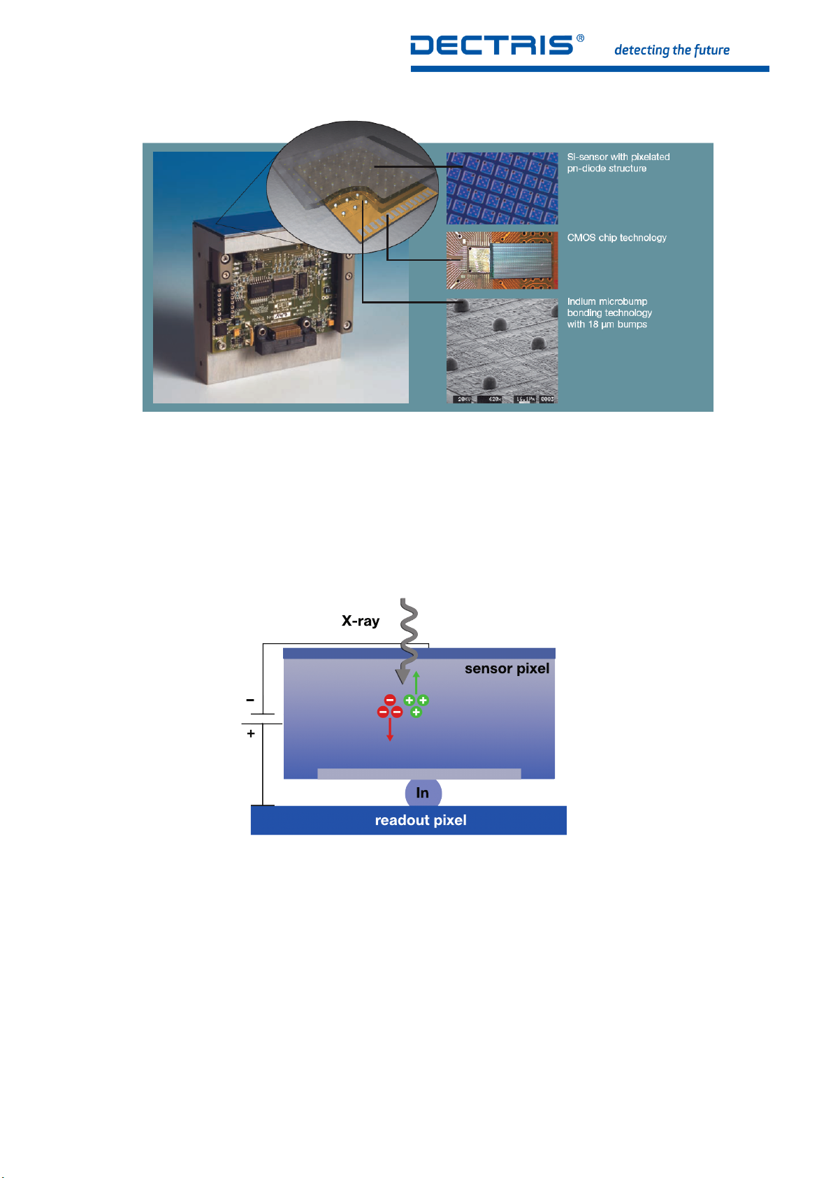
Figure 3.1: The PILATUS3 detector module, the basic element of all DECTRIS Ltd. area detector systems
readout pixel
In
X-ray
+
–
sensor pixel
The quantum efficiency depends on thickness of the silicon sensors, which are available for a wide energy range. The
count rate is greater than 1×10⁷photons/s/pixel, enough to perform many experiments using the high flux of modern
synchrotron light sources. However, the detector cannot withstand a direct synchrotron beam.
3.2.2. Readout Chip
Figure 3.2:
The great advantage of this approach is that standard technologies are used for both the silicon sensor and the CMOS
readout chips, which guarantees highest quality. Both processes are optimized separately, as the best silicon substrates
for X-ray detection and for high-speed/high-quality electronics are very different. Moreover, the small size of the pixel and
the interconnection results in a very low capacitance, which has the beneficial effect of reducing the noise and power
consumption of the pixel readout electronics.
X-ray data collection can be improved with detectors operating in single photon counting mode. A hybrid pixel which features single photon counting comprises a charge-sensitive pre-amplifier (CSA), which amplifies the signal generated in the
sensor by the incoming X-ray, and a comparator (Comp), which produces a digital signal if the incoming charge exceeds a
pre-defined threshold. The comparator feeds a 20 bit counter, which then leads to completely digital storage and noiseless
readout of the number of detected X-rays in each pixel (see figure 3.3).
Principle of Direct Detection
PILATUS3 R/S/X User Manual v1.1.0 5 | 48

Figure 3.3: Design of the Photon Counting Circuit in each Pixel
The fundamental unit of the DECTRIS detectors, the module, consists of a single fully depleted monolithic silicon sensor
with an 8 x 2 array of CMOS readout chips bump-bonded to it. Each sensor is a continuous array of 487 pixel x 195 pixel
= 94 965 pixel without dead areas and covers an active area of 33.5 mm x 83.8 mm = 2807.3 mm2. The readout chips are
wire-bonded to the underlying print, which is glued to the mounting bracket. Together with its readout control electronics
the sensor with readout chips forms the complete module.
3.2.3. Instant Retrigger
The PILATUS3 X-ray features an instant retrigger capability, improved high-rate counting performance. Instant retrigger capability results in non-paralyzable counting and allows for enhanced count-rate correction. In addition, the PILATUS3 detectors
features various enhancements such as counter overflow handling, improved pixel uniformity and reduced crosstalk.
Instant retrigger technology with adjustable dead time is a photon counting imaging method that results in non-paralyzable
counting and achieves an improved high-rate counting performance. In a conventional single-photon counting X-ray detector, the charge pulses generated by impinging photons are counted by digital circuits. Simultaneously generated pulses can
pile up and as a result, photon counts can be lost. At high photon fluxes, pulse pile-up significantly affects the observed
count rate and can lead to complete paralyzation of the counting circuit. In the first generation series of single-photon counting hybrid pixel X-ray detectors ”PILATUS3 ”, count rate correction is applied in order to compensate for the counting loss at
high count rates. However, counter paralyzation limits the maximum usable count rate. In PILATUS3 detectors, the instant
retrigger technology re-evaluates the pulse signal after a predetermined dead-time interval after each count and is able to
retrigger the counting circuit should a pulse pile-up occur. The dead time interval is adjustable and is equivalent to the width
of one single photon pulse. This results in non-paralyzable counting and allows for enhanced count-rate correction so as to
achieve improved data quality at high count rates.
PILATUS3 R/S/X User Manual v1.1.0 6 | 48
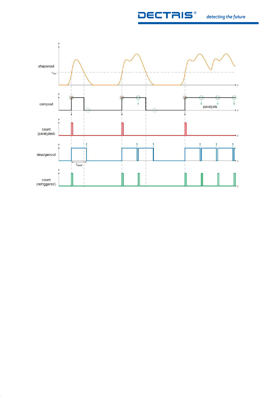
Figure 3.4: Signal Waveforms Illustrating Instant Retrigger Technology
The principle of instant retrigger technology is illustrated in figure 3.4. The first diagram shows the signal pulses generated
by impinging photons and the effective discriminator threshold level for single photon counting. The pulse signal includes
a series of one single pulse, a pile-up of two pulses and a pile-up of multiple pulses. The second diagram shows the corresponding digital discriminator output signal that triggers the counting circuit. The third diagram shows the corresponding
counts being registered by a conventional single photon counting X-ray detector, clearly illustrating that counts are lost in the
case of pulse pile-up and that this can lead to paralyzation. The fourth diagram shows the respective dead-time generator
output signal provided by a single photon counting X-ray detector with instant retrigger technology. Here, a predefined dead
time interval is started whenever a count has been registered. The fifth diagram shows the corresponding counts being
registered, including potential retriggering of the counting circuit after the dead-time interval after each count. This clearly
illustrates that pulses are counted more accurately in the case of pile-up and that counting is non-paralyzable.
3.3. Software
The PILATUS3 detector system is controlled via Camserver.
3.3.1. Overview of Camserver
Camserver is a freestanding program that controls the PILATUS3 detector and provides a simple user interface for ”atomic”
(single function) commands. It is intended to provide a minimal, but fully functional, low level interface to camera hardware.
On invocation, Camserver takes one optional command-line argument, the path to its resource file, by default called camrc.
Camserver will also use the same path to open its debugging file, camdbg.out. For standard operation the argument does
not have to be defined.
A major feature of Camserver is to accept TCP socket connections from a high level controller, which can provide high level
services to this or other cameras. (see chapter 6 and 13 for more details). The interface is a simple text-based message
passing system. Images - the ultimate product of a working area X-ray detector - do not pass through the socket interface,
but are written to a configurable location on the detector server’s filesystem (e.g., a NFS mount) where any program can
access them.
PILATUS3 R/S/X User Manual v1.1.0 7 | 48

3.3.2. Configuration Directories and Files for Camserver
In the default setup, all necessary data for use of the PILATUS3 detector system is in the directories:
Table 3.1: Camserver Directories
Directory Description
/usr/local/bin/ Camserver executable
/etc/dectris/ Camserver configuration file
/var/tmp/dectris/camstat/ Camserver status files
/var/log/dectris/ Camserver log files
/var/local/lib/dectris/config/cam_data/ Detector configuration files
/var/local/lib/dectris/config/calibration/ Detector calibration data
/home/det/images Default image directory
The configuration files from the detector and Camserver:
Table 3.2: Camserver Directories
File Name Description
/etc/dectris/camrc Camserver configuration containing all details and links to further
configurations files
/var/local/lib/dectris/config/cam_data
/camera.def
/var/local/lib/dectris/config/cam_data
/pidet.set
Detector configuration file containing the information about the detector: serial number, sensor thickness, rate correction.
Contains the start procedure for Camserver.
1
Information #1
Please note that this startup configuration is only valid until a high level controller sets a new one (e.g. see
section 3.3.4 and section 5.1).
3.3.3. Overview of TVX
TVX is a free, open source, data acquisition and control software suite tailored to X-ray science. TVX is an attempt to provide
a flexible user interface that is easily adapted to control a broad range of 2D X-ray detectors as well as a powerful collection
of analysis tools.
The suite operates by distributing the tasks of data analysis and hardware control between two separate programs. TVX
contains a user interface and analysis tool suite. TVX communicates over a TCP/IP connection to Camserver.
3.3.4. Configuration Files for TVX
In the default setup, all data for the use of TVX with the PILATUS3 detector system are in the directory /home/det/tvx. Important configuration files are listed in the following table. The directory is given relative to the default path /home/det/tvx/.
PILATUS3 R/S/X User Manual v1.1.0 8 | 48

Table 3.3: TVX Configuration Files
File Directory Description
tvxrc ./ Configuration file for TVX
default.gl config Startup glossary of TVX
det_spec.gl config Detector specific parameters for TVX
user.gl config User short cuts for TVX
startup.gl config Final startup glossary executing detector self-tests
(see section 5.1 for more details)
3.3.5. Compatibility to Earlier Configurations of Camserver and TVX
Earlier models of PILATUS3 detectors contained all configuration files below the /home/det/p2_det directory. To preserve
compatibility the original file structure is mapped with links. The following table shows the relationship between links and
physical directories on the filesystem of the detector server. Please note that not all files within the directories are mapped
one-to-one.
Table 3.4: Relationship between Link and Physical Directory
Physical Directory Symbolic Link
/home/det/tvx/ /home/det/p2_det/
/home/det/images /home/det/p2_det/images/
/var/local/lib/dectris/config/ /home/det/p2_det/config/
/var/tmp/dectris/camstat/ /home/det/p2_det/config/camstat/
/var/log/dectris/ /home/det/p2_det/camdbg_logs/
PILATUS3 R/S/X User Manual v1.1.0 9 | 48
4. QUICK START GUIDE
Before you turn on the system, make sure you have read this user documentation, the Technical Specifications, and set up
the detector accordingly.
• Turn on the detector server.
• Log in procedure: Enter User and password (provided on a separate sheet in your user documentation folder)
• Open a shell.
• Change to the TVX directory. All following paths are given relative to this!
cd/home/det/tvx
• Run TVX by typing
./runtvx
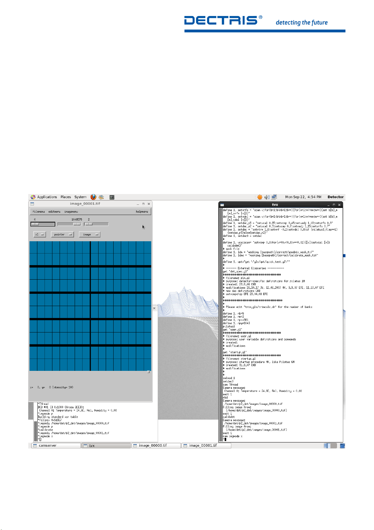
After the initialization (∼ 20 s) you should get the following screen:
Figure 4.1: Startup Screen after Executing ./runtvx
• The command ./runtvx is a shell script, which starts the program Camserver (window on the left side of figure 4.1) and
TVX (window on the right side of figure 4.1) as well as manages all log files.
• During startup the detector sets several parameters defined in the startup scripts (details in section 5.1).
PILATUS3 R/S/X User Manual v1.1.0 10 | 48

• Once two images (green and blue) appear on the screen the detector is ready to operate. In figure 4.1 only one
(blue) image is visible since it is above the other (green) one. Both terminals (TVX and Camserver) have their prompt,
indicated by an asterisk symbol (*).
• The detector is now ready for operation with Copper (8 keV) radiation. If you would like to change to other energies
please see chapter 7.
• To take an image you can type expose 10 in the TVX window, where 10 is the exposure time in seconds.
Further information:
• Details on how to control the detector from a specific environment (e.g. at a synchrotron) can be found in section 5.2.
• Details on how to trigger the detector with an external signal can be found in section 6.3.
• For information concerning the dead pixels and gaps please see chapter 8.
PILATUS3 R/S/X User Manual v1.1.0 11 | 48
 Loading...