

Dectris PILATUS 1M Operating Procedures Manual
Technical Specification
and
Operating Procedure
PILATUS 1M
Detector System
Version 1.7

Technical_Specification_PILATUS_1M_V1_7 2/31
Table of Contents
1 DOCUMENT HISTORY ................................................................................................................ 3
1.1 CHANGES ....................................................................................................................................... 3
2 HOW TO USE THIS TECHNICAL SPECIFICATION .......................................................................... 4
2.1 ADDRESS AND SUPPORT ................................................................................................................... 4
2.2 EXPLANATION OF SYMBOLS ............................................................................................................... 5
2.3 EXPLANATION OF TERMS .................................................................................................................. 5
2.4 USE OF THE PILATUS 1M ................................................................................................................ 5
3 TECHNICAL SPECIFICATION ....................................................................................................... 6
3.1 RATINGS ........................................................................................................................................ 7
3.2 AMBIENT CONDITIONS ..................................................................................................................... 8
4 DIMENSIONS AND CONNECTORS .............................................................................................. 9
4.1 PILATUS 1M DETECTOR.................................................................................................................. 10
4.1.1 Front Side of the Detector ............................................................................................... 10
4.1.2 Backside of the Detector ................................................................................................. 12
4.1.3 The status LEDs ............................................................................................................... 12
4.1.4 Connectors and Connecting Cables/Pipes ....................................................................... 13
4.2 COMPUTER .................................................................................................................................. 15
4.3 COOLING UNIT ............................................................................................................................. 16
5 INSTALLING THE DETECTOR SYSTEM ....................................................................................... 17
5.1 CARRYING .................................................................................................................................... 17
5.2 MOUNTING .................................................................................................................................. 19
5.2.1 Mounting from Above ..................................................................................................... 19
5.2.2 Mounting from Below ..................................................................................................... 20
5.3 GROUNDING OF THE DETECTOR SYSTEM ............................................................................................ 21
5.4 CONNECTION TO NITROGEN OR DRY AIR ............................................................................................ 22
5.5 CONNECTING THE CABLES ............................................................................................................... 23
6 TEMPERATURE AND HUMIDITY CONTROL .............................................................................. 24
7 GETTING STARTED .................................................................................................................. 26
7.1 STARTUP SEQUENCE ...................................................................................................................... 26
7.2 FIRST COMMANDS ......................................................................................................................... 27
8 TURNING OFF THE DETECTOR ................................................................................................. 28
9 STORING THE DETECTOR ......................................................................................................... 28
10 CLEANING AND MAINTENANCE .............................................................................................. 29
11 FAULTS .................................................................................................................................... 30
12 CERTIFICATION TESTS ............................................................................................................. 31

Technical_Specification_PILATUS_1M_V1_7 3/31
1 Document History
Actual document
Version
Date
status
prepared
checked
released
1.7
22.07.2011
released
PS,BS
SC, DB
SB
1.1 Changes
Version
Date
Changes
released
1.0
02.06.2009
PS
1.4
29.01.2010
Connection cables and
temperature sensors
SB
1.4.1
18.02.2010
Signal levels
SB
1.4.2
19.02.2010
Power input
SB
1.5
09.04.2010
Dimensions and grounding
SB
1.5.1
21.04.2010
Power supply description
SB
1.5.2
28.05.2010
Dimensions
SB
1.6
04.10.2010
Pictures
SB
1.7
22.07.2011
Thicker sensors and conformity
with standards
SB

Technical_Specification_PILATUS_1M_V1_7 4/31
2 How to use this Technical
Specification
Before you start to operate the PILATUS 1M detector system please read this
technical specification and the user manual thoroughly.
The technical specification and the user manual together form the user
documentation.
2.1 Address and Support
DECTRIS Ltd.
Neuenhoferstrasse 107
5400 Baden
Switzerland
Phone: +41 56 500 21 00
Fax: + 41 56 500 21 01
Email: support@dectris.com
Should you have questions concerning the system or its use, please contact
us via phone, mail or fax.
Before you ship the system back, please contact us to receive the
necessary transport and shipping information.
Technical_Specification_PILATUS_1M_V1_7 5/31
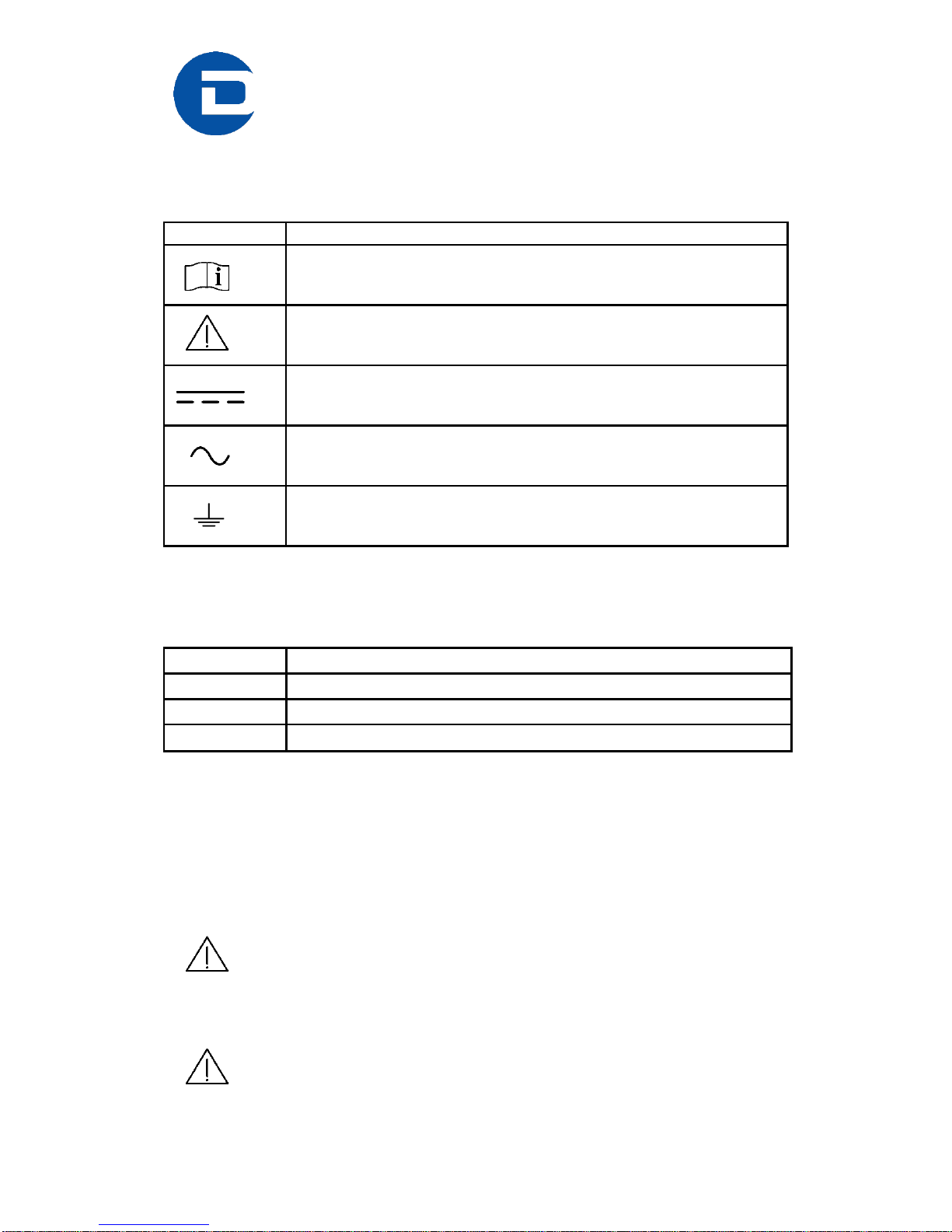
2.2 Explanation of Symbols
Symbol
Description
Important or helpful notice
Caution. Please follow the instructions carefully to prevent
equipment damage or personal injury.
DC-current
AC-current
Ground
2.3 Explanation of Terms
Term
Description
MCB
Module Control Board
DCB
Detector Control Board
DAC
Digital to Analog Converter
2.4 Use of the PILATUS 1M
The PILATUS 1M detector system has been designed for the detection of Xrays from synchrotrons or laboratory sources.
It is intended for indoor use only.
For other applications, please contact DECTRIS for additional information.
Do not use the detector in vacuum
The PC can be mounted in a standard 19 inch rack, which has to be properly
grounded.
Make sure that the PC has adequate ventilation.

Technical_Specification_PILATUS_1M_V1_7 6/31
3 Technical specification
Number of modules
2 x 5 = 10
Sensor
Reverse-biased silicon diode array
Sensor thickness
320 µm 450 µm
3 keV: 48%
8 keV: 95%
15 keV: 51%
3 keV: 48%
8 keV: 96%
15 keV: 64%
Pixel size
172 x 172 µm2
Module size
83.8 x 33.5 mm2
Format
981 x 1043 = 1’023’183 pixels
Area
169 x 179 mm2
Intermodule gap
x: 7 pixels, y: 17 pixels, 8.4% of total area
Dynamic range
20 Bits = 1’048’576
Counting rate per pixel
> 2x10⁶ X-ray/sec
Energy range
4.5 – 36 keV
Energy resolution
500 eV
Adjustable threshold range
4 - 18 keV
Threshold dispersion
50 eV
Readout time
2.3 ms
Framing rate
30 Hz
Point-spread function
1 pixel
Data formats
Raw data, TIF, EDF, CBF
External trigger/gate
3.3 – 5V, 3 different modes
Software interface
Through socket connection;
Clients for EPICS, SPEC and stand-alone
operation are available
Cooling
Water-cooled
Operating temperature (internal)
23°C
Dimensions (W x H x D)
325 x 336 x 458 mm3
Weight
Approx. 25 kg
Technical_Specification_PILATUS_1M_V1_7 7/31
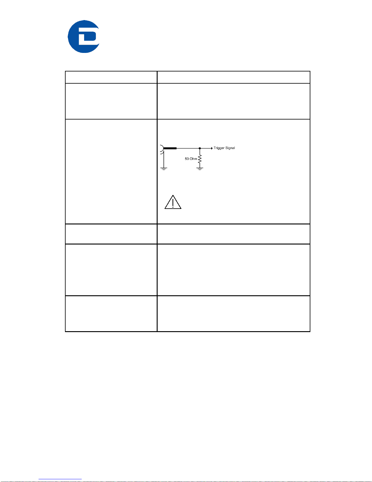
3.1 Ratings
Device
Definition
Detector
Power Input
100 - 240 VAC, 50-60 Hz, 120 Watt
Can be connected to all common supply
voltages.
Detector
External Trigger Input
2.0 V - 5.0 V High level
0.0 V - 0.8 V Low level
50 Ohm Impedance
Trigger Signal … to internal circuit
5.0 V absolute maximum
Applying a higher voltage will destroy
the input.
Detector
Enable output
5 V TTL (max. 100 mA)
PC
100 - 240 VAC; 12 A
50/60 Hz
870 Watt
Hot-Plug Power Supplies
Can be connected to all common supply
voltages.
Cooling unit
230V, 50Hz
Power Input: 2000W
Flow: 14 l/min
Pressure: 0.5 bar

Technical_Specification_PILATUS_1M_V1_7 8/31
3.2 Ambient Conditions
The PILATUS 1M detector is designed only for indoor use. The following
ambient conditions must be fulfilled:
Condition
Range
Operating temperature:
+20° to +35° C
Operating humidity:
80% at 20° C, non-condensing
Storage temperature
+15° to +40° C
Storage humidity
< 40% at 20° C, non-condensing
Note that the interior humidity under operating conditions must be
< 25%, see section 6.
When storing the detector make sure the temperature and humidity
inside the transport box doesn’t exceed the specified range. Use drying agent.
If the detector system is stored at low temperature, make sure that
no condensation moisture develops.
The PILATUS 1M is equipped with a temperature and humidity
control, see section 6.
Technical_Specification_PILATUS_1M_V1_7 9/31
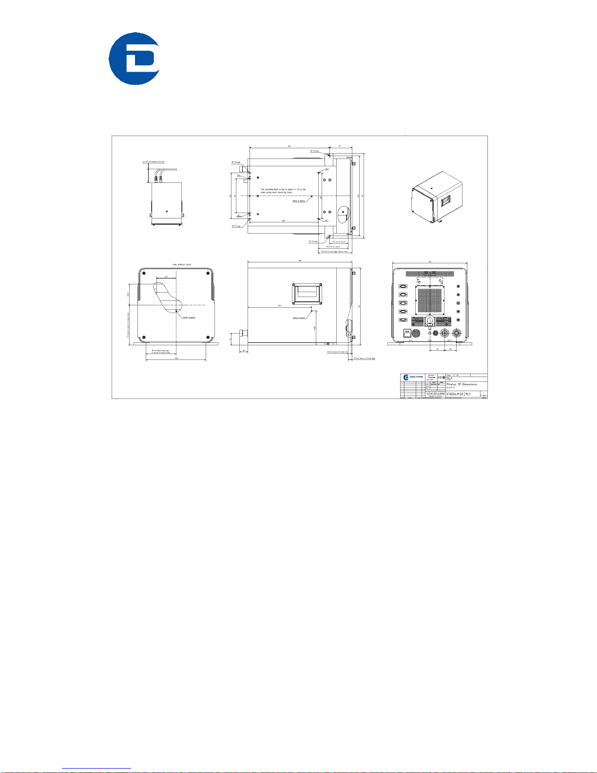
4 Dimensions and Connectors
Figure 1. Drawing of the PILATUS 1M detector (printed separately in the user
documentation folder)
Technical_Specification_PILATUS_1M_V1_7 10/31
4.1 Pilatus 1M Detector
4.1.1 Front Side of the Detector
The detector comes with a protective cover (1.4 mm, low carbon steel sheet
metal 1.0330, St12) for the front window which should be removed for
operation. The sensors are behind a 12 µm thick Mylar ® (PET) foil coated
with 100 nm aluminum to protect it from dust and touch.
The cover has a mounting edge on top and can be removed by carefully
pulling at the bottom and lifting it away.
When mounting the cover, make sure it is first hooked on the mounting edge
centered and then slowly lowered.
Do not touch the Mylar ® foil.
The cover may not protect the detector from direct synchrotron
beam.
Figure 2. PILATUS 1M detector with cover in place (front view)
 Loading...