

DECstation 5000/260 Operator's Manual

Order Number: EK-4MMAX–OP. A01
DECstation5000Model260
Operator’sGuide

March 1993
The information in this document is subject to change without notice and should not be
construed as a commitment by Digital Equipment Corporation. Digital Equipment Corporation
assumes no responsibility for any errors that may appear in this document.
The software described in this document is furnished under a license and may be used or copied
only in accordance with the terms of such license.
Digital Equipment Corporation assumes no responsibility for the use or reliability of its software
on equipment that is not supplied by Digital or its affiliated companies.
© Digital Equipment Corporation 1993.
All Rights Reserved
Printed in U.S.A.
U.S.A.
This equipment generates, uses, and may emit radio frequency energy. The equipment has
been type tested and found to comply with the limits for a Class A computing device pursuant
to Subpart J of Part 15 of FCC Rules, which are designed to provide reasonable protection
against such radio frequency interference. Operation of this equipment in a residential area may
cause interference in which case the user at his own expense will be required to take whatever
measures may be required to correct the interference.
The following are trademarks of Digital Equipment Corporation:
DEC
DECnet
DECstation
DECsystem
DECUS
DESTA
MicroVAX
MicroVMS
PDP
ThinWire
TURBOchannel
ULTRIX
ULTRIX-32
UNIBUS
All other trademarks and registered trademarks are the property of their respective holders.
VAX
VAXBI
VAXcluster
VAXstation
VMS
VT
ML–S2087

Contents
Preface . . . . . . . . . . . . . . . . . . . . . . . . . . . . . . . . . . . . . . . . . . . . . . . . . . . . . xiii
Part I Introducing Your Workstation
1 The Main Components and How to Install Them
1.1 The System Unit . . . . . . . . . . . . . . . . . . . . . . . . . . . . . . . . . . . . . 1–2
1.1.1 Front of the System Unit . . . . . . . . . . . . . . . . . . . . . . . . . . . . 1–3
1.1.2 Back of the System Unit . . . . . . . . . . . . . . . . . . . . . . . . . . . . 1–4
1.1.3 Icons on the System Unit . . . . . . . . . . . . . . . . . . . . . . . . . . . . 1–6
1.1.4 Setting Up the System Unit . . . . . . . . . . . . . . . . . . . . . . . . . . 1–6
1.2 The Monitor . . . . . . . . . . . . . . . . . . . . . . . . . . . . . . . . . . . . . . . . . 1–9
1.2.1 Turning Your Monitor On and Off . . . . . . . . . . . . . . . . . . . . . 1–9
1.2.2 Positioning the Monitor . . . . . . . . . . . . . . . . . . . . . . . . . . . . . 1–10
1.2.3 Connecting the Monitor Video Cable . . . . . . . . . . . . . . . . . . . 1–11
1.2.3.1 To Connect a Color Video Cable . . . . . . . . . . . . . . . . . . . . 1–12
1.2.3.2 To Connect a Gray-scale Video Cable . . . . . . . . . . . . . . . . 1–14
1.2.3.3 To Connect a Monochrome Video Cable . . . . . . . . . . . . . . 1–16
1.2.4 Connecting More Than One Monitor to a Workstation . . . . . . 1–17
1.2.5 Supplying Power to the Monitor . . . . . . . . . . . . . . . . . . . . . . 1–18
1.2.5.1 To Connect the Monitor to the System Unit Power
Outlet . . . . . . . . . . . . . . . . . . . . . . . . . . . . . . . . . . . . . . . . 1–19
1.2.5.2 To Connect the Monitor to an Independent Power
Outlet . . . . . . . . . . . . . . . . . . . . . . . . . . . . . . . . . . . . . . . . 1–21
1.3 Input Devices . . . . . . . . . . . . . . . . . . . . . . . . . . . . . . . . . . . . . . . . 1–23
1.3.1 The Keyboard . . . . . . . . . . . . . . . . . . . . . . . . . . . . . . . . . . . . . 1–23
1.3.1.1 The LK401 Keyboard . . . . . . . . . . . . . . . . . . . . . . . . . . . . 1–23
1.3.1.2 Connecting the Keyboard to the System Unit . . . . . . . . . 1–25
1.3.1.3 Adjusting the Keyboard Feet . . . . . . . . . . . . . . . . . . . . . . 1–29
1.3.2 Pointing Devices . . . . . . . . . . . . . . . . . . . . . . . . . . . . . . . . . . 1–30
1.3.2.1 The Mouse and Tablet . . . . . . . . . . . . . . . . . . . . . . . . . . . 1–30
1.3.2.2 Dial and Button Boxes . . . . . . . . . . . . . . . . . . . . . . . . . . . 1–33
iii

1.4 Adjusting and Positioning Your Workstation for Comfort . . . . . . . 1–34
2 The Environment
2.1 Site Requirements . . . . . . . . . . . . . . . . . . . . . . . . . . . . . . . . . . . . 2–1
2.1.1 Temperature and Humidity . . . . . . . . . . . . . . . . . . . . . . . . . . 2–1
2.1.2 Cleanliness . . . . . . . . . . . . . . . . . . . . . . . . . . . . . . . . . . . . . . . 2–2
2.1.3 Interference . . . . . . . . . . . . . . . . . . . . . . . . . . . . . . . . . . . . . . 2–2
2.2 Electrical Requirements . . . . . . . . . . . . . . . . . . . . . . . . . . . . . . . . 2–2
2.2.1 Voltage . . . . . . . . . . . . . . . . . . . . . . . . . . . . . . . . . . . . . . . . . . 2–3
3 Starting and Testing
3.1 Turning On Your Workstation . . . . . . . . . . . . . . . . . . . . . . . . . . . 3–2
3.2 Setting the Keyboard Language . . . . . . . . . . . . . . . . . . . . . . . . . . 3–5
3.3 Testing Your Workstation . . . . . . . . . . . . . . . . . . . . . . . . . . . . . . . 3–6
3.3.1 Using the Quick or Full Self-Test . . . . . . . . . . . . . . . . . . . . . . 3–6
3.3.2 To Run the Full Self-Test . . . . . . . . . . . . . . . . . . . . . . . . . . . . 3–7
3.3.3 If a Self-Test Fails . . . . . . . . . . . . . . . . . . . . . . . . . . . . . . . . . 3–7
3.4 Checking the Configuration Display . . . . . . . . . . . . . . . . . . . . . . . 3–7
3.5 Stopping the Workstation Without Turning It Off . . . . . . . . . . . . 3–8
3.6 Turning Off the Workstation . . . . . . . . . . . . . . . . . . . . . . . . . . . . 3–9
3.7 Installing Workstation Software . . . . . . . . . . . . . . . . . . . . . . . . . 3–10
4 Moving Your Workstation
4.1 Dismantling Your Workstation . . . . . . . . . . . . . . . . . . . . . . . . . . . 4–1
4.2 Packing Your Equipment . . . . . . . . . . . . . . . . . . . . . . . . . . . . . . . 4–2
Part II External Additions to Your Workstation
5 External Storage Devices
5.1 Available External Options . . . . . . . . . . . . . . . . . . . . . . . . . . . . . 5–2
5.2 Storage Devices You Can Add to Your Workstation . . . . . . . . . . . 5–2
5.3 Rules for Connecting Storage Devices . . . . . . . . . . . . . . . . . . . . . 5–4
5.4 Installing External Storage Devices . . . . . . . . . . . . . . . . . . . . . . . 5–5
5.5 SCSI Cable Length . . . . . . . . . . . . . . . . . . . . . . . . . . . . . . . . . . . 5–16
5.6 Checking and Setting SCSI ID Numbers . . . . . . . . . . . . . . . . . . . 5–17
5.6.1 To Check the SCSI ID . . . . . . . . . . . . . . . . . . . . . . . . . . . . . . 5–17
5.6.2 To Set the SCSI ID . . . . . . . . . . . . . . . . . . . . . . . . . . . . . . . . 5–17
5.7 Testing External Storage Devices . . . . . . . . . . . . . . . . . . . . . . . . . 5–19
iv

5.8 Removing an External Storage Device . . . . . . . . . . . . . . . . . . . . . 5–21
5.9 Installing a Drive in an Expansion Box . . . . . . . . . . . . . . . . . . . . 5–21
6 Optional Network Connections
6.1 Locating Your Workstation Ethernet Connector . . . . . . . . . . . . . . 6–2
6.2 Installing and Removing an Ethernet Loopback Connector . . . . . 6–2
6.3 Operating the Ethernet Connector Sliding Lock . . . . . . . . . . . . . 6–3
6.4 Finding Your Ethernet Station Address . . . . . . . . . . . . . . . . . . . . 6–7
6.5 Connecting the Workstation to an Ethernet Network . . . . . . . . . 6–8
6.5.1 To Connect a ThickWire Ethernet Cable . . . . . . . . . . . . . . . . 6–9
6.5.2 To Connect a ThinWire Ethernet Adapter . . . . . . . . . . . . . . . 6–12
6.5.3 To Connect a Twisted-Pair Ethernet Adapter . . . . . . . . . . . . . 6–16
7 External Communications Options
7.1 External Communications Options . . . . . . . . . . . . . . . . . . . . . . . . 7–2
7.2 Types of Connectors . . . . . . . . . . . . . . . . . . . . . . . . . . . . . . . . . . . 7–3
7.3 Installing a Device with a 25-Pin Connector . . . . . . . . . . . . . . . . 7–4
7.4 Installing a Device with a Modular Connector . . . . . . . . . . . . . . . 7–7
Part III Internal Parts and Additions to Your Workstation
8 Inside the System Unit
8.1 Available Internal Options . . . . . . . . . . . . . . . . . . . . . . . . . . . . . . 8–2
8.2 Main Parts of the System Unit . . . . . . . . . . . . . . . . . . . . . . . . . . 8–2
8.2.1 The Base System Module . . . . . . . . . . . . . . . . . . . . . . . . . . . . 8–3
8.2.2 Memory Modules . . . . . . . . . . . . . . . . . . . . . . . . . . . . . . . . . . 8–3
8.2.3 Nonvolatile Random-Access Memory (NVRAM) Module . . . . . 8–4
8.2.4 The CPU Module . . . . . . . . . . . . . . . . . . . . . . . . . . . . . . . . . . 8–4
8.2.5 TURBOchannel Option Modules . . . . . . . . . . . . . . . . . . . . . . 8–4
8.2.6 The Power Supply . . . . . . . . . . . . . . . . . . . . . . . . . . . . . . . . . 8–5
8.3 Removing and Replacing the System Unit Cover . . . . . . . . . . . . . 8–6
8.3.1 To Remove the Cover from the System Unit . . . . . . . . . . . . . 8–6
8.3.2 To Replace the Cover on the System Unit . . . . . . . . . . . . . . . 8–7
8.4 Using the Antistatic Wrist Strap . . . . . . . . . . . . . . . . . . . . . . . . . 8–8
v

9 Installing Internal Option Modules
9.1 Installing and Removing Memory . . . . . . . . . . . . . . . . . . . . . . . . 9–2
9.1.1 To Install Memory Modules . . . . . . . . . . . . . . . . . . . . . . . . . . 9–3
9.1.2 To Test Memory Modules . . . . . . . . . . . . . . . . . . . . . . . . . . . . 9–7
9.1.3 To Remove Memory Modules . . . . . . . . . . . . . . . . . . . . . . . . . 9–8
9.2 Installing and Removing a PrestoServe/NVRAM Module . . . . . . . 9–11
9.3 Replacing CPU Modules . . . . . . . . . . . . . . . . . . . . . . . . . . . . . . . . 9–13
9.3.1 To Remove a CPU Module . . . . . . . . . . . . . . . . . . . . . . . . . . . 9–13
9.3.2 To Install a New CPU Module . . . . . . . . . . . . . . . . . . . . . . . . 9–19
9.3.3 To Test the CPU Module . . . . . . . . . . . . . . . . . . . . . . . . . . . . 9–23
9.4 Installing and Removing TURBOchannel Option Modules . . . . . . 9–24
Part IV Managing Your Workstation
10 Using the Console Commands
10.1 Console and Operating Modes . . . . . . . . . . . . . . . . . . . . . . . . . . . 10–2
10.2 Using Console Mode . . . . . . . . . . . . . . . . . . . . . . . . . . . . . . . . . . . 10–2
10.2.1 To Enter Console Mode . . . . . . . . . . . . . . . . . . . . . . . . . . . . . 10–3
10.2.2 Console Prompts . . . . . . . . . . . . . . . . . . . . . . . . . . . . . . . . . . 10–3
10.3 Installing a Terminal as an Alternate System Console . . . . . . . . 10–4
10.3.1 To Install a Terminal as a System Console . . . . . . . . . . . . . . 10–4
10.3.2 To Activate the Terminal as the System Console . . . . . . . . . . 10–6
10.3.3 To Make Your Workstation Monitor the System Console . . . . 10–7
10.4 Rules for Console Commands . . . . . . . . . . . . . . . . . . . . . . . . . . . 10–8
10.5 Conventions Used . . . . . . . . . . . . . . . . . . . . . . . . . . . . . . . . . . . . 10–9
10.6 Console Commands . . . . . . . . . . . . . . . . . . . . . . . . . . . . . . . . . . . 10–10
10.6.1 ? . . . . . . . . . . . . . . . . . . . . . . . . . . . . . . . . . . . . . . . . . . . . . . . 10–11
10.6.2 boot . . . . . . . . . . . . . . . . . . . . . . . . . . . . . . . . . . . . . . . . . . . . 10–11
10.6.3 cat . . . . . . . . . . . . . . . . . . . . . . . . . . . . . . . . . . . . . . . . . . . . . 10–12
10.6.4 cnfg . . . . . . . . . . . . . . . . . . . . . . . . . . . . . . . . . . . . . . . . . . . . 10–13
10.6.5 d . . . . . . . . . . . . . . . . . . . . . . . . . . . . . . . . . . . . . . . . . . . . . . . 10–17
10.6.6 e . . . . . . . . . . . . . . . . . . . . . . . . . . . . . . . . . . . . . . . . . . . . . . . 10–18
10.6.7 erl . . . . . . . . . . . . . . . . . . . . . . . . . . . . . . . . . . . . . . . . . . . . . 10–18
10.6.8 go . . . . . . . . . . . . . . . . . . . . . . . . . . . . . . . . . . . . . . . . . . . . . . 10–19
10.6.9 init . . . . . . . . . . . . . . . . . . . . . . . . . . . . . . . . . . . . . . . . . . . . . 10–19
10.6.10 ls . . . . . . . . . . . . . . . . . . . . . . . . . . . . . . . . . . . . . . . . . . . . . . 10–19
10.6.11 passwd . . . . . . . . . . . . . . . . . . . . . . . . . . . . . . . . . . . . . . . . . . 10–19
10.6.12 printenv . . . . . . . . . . . . . . . . . . . . . . . . . . . . . . . . . . . . . . . . . 10–20
10.6.13 restart . . . . . . . . . . . . . . . . . . . . . . . . . . . . . . . . . . . . . . . . . . 10–21
10.6.14 script . . . . . . . . . . . . . . . . . . . . . . . . . . . . . . . . . . . . . . . . . . . 10–21
10.6.15 setenv. . . . . . . . . . . . . . . . . . . . . . . . . . . . . . . . . . . . . . . . . . . 10–21
vi

10.6.16 sh . . . . . . . . . . . . . . . . . . . . . . . . . . . . . . . . . . . . . . . . . . . . . . 10–21
10.6.17 t . . . . . . . . . . . . . . . . . . . . . . . . . . . . . . . . . . . . . . . . . . . . . . . 10–22
10.6.18 unsetenv . . . . . . . . . . . . . . . . . . . . . . . . . . . . . . . . . . . . . . . . 10–22
10.7 Environmental Variables . . . . . . . . . . . . . . . . . . . . . . . . . . . . . . . 10–23
11 Troubleshooting
11.1 Where to Look in This Manual for Help . . . . . . . . . . . . . . . . . . . . 11–2
11.2 Checking the LED Display . . . . . . . . . . . . . . . . . . . . . . . . . . . . . . 11–2
11.3 Is It Connected Properly? . . . . . . . . . . . . . . . . . . . . . . . . . . . . . . . 11–6
11.4 Using a Full System Self-Test . . . . . . . . . . . . . . . . . . . . . . . . . . . 11–15
11.5 Interpreting Self-Test Messages . . . . . . . . . . . . . . . . . . . . . . . . . . 11–16
11.6 Contacting Your Customer Support Center . . . . . . . . . . . . . . . . . 11–20
Part V Appendixes
A Equipment Specifications
A.1 DECstation 5000 Model 260 System Unit Equipment
Specifications . . . . . . . . . . . . . . . . . . . . . . . . . . . . . . . . . . . . . . . . A–1
B Connector Pin Assignments
C Regulatory Information for the United Kingdom
C.1 Service Requirements . . . . . . . . . . . . . . . . . . . . . . . . . . . . . . . . . C–2
C.2 Approvals for Digital Circuits . . . . . . . . . . . . . . . . . . . . . . . . . . . C–2
C.3 Host Independent Approvals . . . . . . . . . . . . . . . . . . . . . . . . . . . . C–5
C.4 Host Power Rating . . . . . . . . . . . . . . . . . . . . . . . . . . . . . . . . . . . . C–6
C.5 Apparatus Between the Approved Apparatus and a Digital
Circuit (PTT) . . . . . . . . . . . . . . . . . . . . . . . . . . . . . . . . . . . . . . . . C–6
Index
vii

Figures
1–1 Front of the system unit . . . . . . . . . . . . . . . . . . . . . . . . . . . . 1–3
1–2 Back of the system unit . . . . . . . . . . . . . . . . . . . . . . . . . . . . . 1–4
1–3 Icons on the system unit . . . . . . . . . . . . . . . . . . . . . . . . . . . . 1–6
1–4 Attaching a ThickWire Ethernet loopback connector . . . . . . . 1–7
1–5 Connecting the power cord to the system unit . . . . . . . . . . . . 1–8
1–6 Turning off your monitor . . . . . . . . . . . . . . . . . . . . . . . . . . . . 1–10
1–7 Turning on your monitor . . . . . . . . . . . . . . . . . . . . . . . . . . . . 1–10
1–8 Video cable assemblies . . . . . . . . . . . . . . . . . . . . . . . . . . . . . . 1–11
1–9 Connecting a video cable assembly to a color monitor . . . . . . 1–12
1–10 Connecting a color video cable to the system unit . . . . . . . . . 1–13
1–11 Connecting a video cable assembly to a gray-scale
monitor . . . . . . . . . . . . . . . . . . . . . . . . . . . . . . . . . . . . . . . . . 1–14
1–12 Connecting a grey-scale video cable assembly to the system
unit . . . . . . . . . . . . . . . . . . . . . . . . . . . . . . . . . . . . . . . . . . . . 1–15
1–13 Connecting a video cable assembly to a monochrome
monitor . . . . . . . . . . . . . . . . . . . . . . . . . . . . . . . . . . . . . . . . . 1–16
1–14 Connecting a monochrome video cable assembly to the
system unit . . . . . . . . . . . . . . . . . . . . . . . . . . . . . . . . . . . . . . 1–17
1–15 Monitor-to-system-unit power cable . . . . . . . . . . . . . . . . . . . . 1–19
1–16 Connecting the monitor-to-system-unit power cable . . . . . . . . 1–20
1–17 Monitor power cord . . . . . . . . . . . . . . . . . . . . . . . . . . . . . . . . 1–21
1–18 Connecting a separate monitor power cord . . . . . . . . . . . . . . 1–22
1–19 LK401 keyboard . . . . . . . . . . . . . . . . . . . . . . . . . . . . . . . . . . . 1–24
1–20 Keyboard-mouse cable assembly . . . . . . . . . . . . . . . . . . . . . . 1–25
1–21 Connecting the keyboard-mouse cable assembly to the
system unit . . . . . . . . . . . . . . . . . . . . . . . . . . . . . . . . . . . . . . 1–26
1–22 Connecting the keyboard cable to the connector block . . . . . . 1–27
1–23 Positioning the connector block . . . . . . . . . . . . . . . . . . . . . . . 1–28
1–24 Raising and lowering the hinged feet on the keyboard . . . . . . 1–29
1–25 Pointing devices . . . . . . . . . . . . . . . . . . . . . . . . . . . . . . . . . . . 1–31
1–26 Connecting the mouse or tablet . . . . . . . . . . . . . . . . . . . . . . . 1–32
1–27 Dial and button boxes . . . . . . . . . . . . . . . . . . . . . . . . . . . . . . 1–33
2–1 Voltage Labels . . . . . . . . . . . . . . . . . . . . . . . . . . . . . . . . . . . . 2–3
3–1 Turning on the system unit . . . . . . . . . . . . . . . . . . . . . . . . . . 3–3
3–2 Halt button and system unit on/off switch . . . . . . . . . . . . . . . 3–9
5–1 Some typical expansion boxes . . . . . . . . . . . . . . . . . . . . . . . . 5–3
viii

5–2 Power switch in the off position . . . . . . . . . . . . . . . . . . . . . . . 5–5
5–3 System-unit-to-expansion-box cable . . . . . . . . . . . . . . . . . . . . 5–6
5–4 Connecting the system-unit-to-expansion-box cable to the
system unit . . . . . . . . . . . . . . . . . . . . . . . . . . . . . . . . . . . . . . 5–7
5–5 Connecting the system-unit-to-expansion-box cable to
expansion box . . . . . . . . . . . . . . . . . . . . . . . . . . . . . . . . . . . . . 5–8
5–6 SCSI box-to-box cable . . . . . . . . . . . . . . . . . . . . . . . . . . . . . . . 5–9
5–7 Connecting an additional non-TCE expansion box to the first
box . . . . . . . . . . . . . . . . . . . . . . . . . . . . . . . . . . . . . . . . . . . . . 5–10
5–8 TCE-to-expansion-box cable . . . . . . . . . . . . . . . . . . . . . . . . . . 5–11
5–9 Connecting the TCE to the expansion box . . . . . . . . . . . . . . . 5–12
5–10 Connecting a SCSI drive terminator . . . . . . . . . . . . . . . . . . . 5–13
5–11 Connecting the power cord . . . . . . . . . . . . . . . . . . . . . . . . . . . 5–14
6–1 Installing and removing an Ethernet loopback connector . . . 6–3
6–2 Unlocking the Ethernet sliding lock . . . . . . . . . . . . . . . . . . . . 6–4
6–3 Locking the Ethernet sliding lock . . . . . . . . . . . . . . . . . . . . . 6–6
6–4 ThickWire Ethernet cable . . . . . . . . . . . . . . . . . . . . . . . . . . . 6–9
6–5 Connecting a ThickWire Ethernet cable to the system
unit . . . . . . . . . . . . . . . . . . . . . . . . . . . . . . . . . . . . . . . . . . . . 6–10
6–6 Parts used to connect a workstation to a ThinWire
network . . . . . . . . . . . . . . . . . . . . . . . . . . . . . . . . . . . . . . . . . 6–12
6–7 Connecting a ThickWire cable to the ThinWire adapter . . . . . 6–13
6–8 Attaching a T-connector . . . . . . . . . . . . . . . . . . . . . . . . . . . . . 6–14
6–9 Attaching a T-connector terminator . . . . . . . . . . . . . . . . . . . . 6–15
6–10 Parts used to connect a workstation to a twisted-pair
Ethernet network . . . . . . . . . . . . . . . . . . . . . . . . . . . . . . . . . . 6–16
6–11 Connecting the ThickWire-to-twisted-pair-adapter . . . . . . . . . 6–17
6–12 Connecting the twisted-pair cable to the twisted-pair
adapter . . . . . . . . . . . . . . . . . . . . . . . . . . . . . . . . . . . . . . . . . . 6–18
7–1 Communications connectors on the system unit . . . . . . . . . . . 7–2
7–2 Communications device connectors and an adapter . . . . . . . . 7–3
7–3 Connecting a communications device with a 25-pin
connector . . . . . . . . . . . . . . . . . . . . . . . . . . . . . . . . . . . . . . . . 7–5
7–4 Using an adapter to connect a communications device with a
modular connector . . . . . . . . . . . . . . . . . . . . . . . . . . . . . . . . . 7–8
8–1 Inside of the system unit enclosure . . . . . . . . . . . . . . . . . . . . 8–2
8–2 Removing and replacing the system unit cover . . . . . . . . . . . 8–7
8–3 Using an antistatic wrist strap . . . . . . . . . . . . . . . . . . . . . . . 8–9
ix

9–1 Releasing the memory module bracket . . . . . . . . . . . . . . . . . . 9–4
9–2 Memory module . . . . . . . . . . . . . . . . . . . . . . . . . . . . . . . . . . . 9–5
9–3 Memory slots inside the system unit . . . . . . . . . . . . . . . . . . . 9–6
9–4 Releasing the memory module bracket . . . . . . . . . . . . . . . . . . 9–9
9–5 Removing a memory module . . . . . . . . . . . . . . . . . . . . . . . . . 9–10
9–6 Removing the Cover . . . . . . . . . . . . . . . . . . . . . . . . . . . . . . . . 9–14
9–7 Attaching the Wrist Strap . . . . . . . . . . . . . . . . . . . . . . . . . . . 9–15
9–8 Attaching the Rivets . . . . . . . . . . . . . . . . . . . . . . . . . . . . . . . 9–16
9–9 Removing the Old CPU . . . . . . . . . . . . . . . . . . . . . . . . . . . . . 9–17
9–10 Inserting the Grounding Clips . . . . . . . . . . . . . . . . . . . . . . . . 9–18
9–11 Adding the New CPU . . . . . . . . . . . . . . . . . . . . . . . . . . . . . . . 9–19
9–12 Replace the Medallion . . . . . . . . . . . . . . . . . . . . . . . . . . . . . . 9–20
9–13 Add the Labels . . . . . . . . . . . . . . . . . . . . . . . . . . . . . . . . . . . . 9–21
9–14 Replace the Cover . . . . . . . . . . . . . . . . . . . . . . . . . . . . . . . . . 9–22
9–15 Return the Old CPU . . . . . . . . . . . . . . . . . . . . . . . . . . . . . . . 9–23
10–1 Connecting a VT320 terminal to the system unit . . . . . . . . . . 10–5
11–1 Indicator light and LED display . . . . . . . . . . . . . . . . . . . . . . . 11–3
C–1 System Module J-Connector Locations . . . . . . . . . . . . . . . . . . C–4
Tables
1 Conventions Used in This Guide . . . . . . . . . . . . . . . . . . . . . . xiv
1–1 Connectors, Controls, LED Display, and Lights on the
System Unit . . . . . . . . . . . . . . . . . . . . . . . . . . . . . . . . . . . . . . 1–5
5–1 SCSI Cable Lengths . . . . . . . . . . . . . . . . . . . . . . . . . . . . . . . . 5–16
5–2 Usual SCSI ID Assignments for External Drives . . . . . . . . . . 5–17
5–3 SCSI ID Switch Settings . . . . . . . . . . . . . . . . . . . . . . . . . . . . 5–18
5–4 Device Codes for Different Types of SCSI Drives . . . . . . . . . . 5–20
10–1 Console Commands . . . . . . . . . . . . . . . . . . . . . . . . . . . . . . . . 10–10
10–2 Module Codes . . . . . . . . . . . . . . . . . . . . . . . . . . . . . . . . . . . . . 10–14
10–3 SCSI Device Codes and Descriptors . . . . . . . . . . . . . . . . . . . . 10–17
10–4 Console Commands for Environmental Variables. . . . . . . . . . 10–23
10–5 Environmental Variables Set by User . . . . . . . . . . . . . . . . . . 10–24
11–1 Interpreting the LED Codes . . . . . . . . . . . . . . . . . . . . . . . . . . 11–4
11–2 Solutions to Common Problems . . . . . . . . . . . . . . . . . . . . . . . 11–6
11–3 Self-Test Error Messages for the Base System Slot . . . . . . . . 11–16
A–1 System Unit Description . . . . . . . . . . . . . . . . . . . . . . . . . . . . A–1
x

A–2 System Unit Operating Conditions . . . . . . . . . . . . . . . . . . . . A–2
A–3 System Unit Nonoperating Conditions . . . . . . . . . . . . . . . . . . A–2
A–4 Acoustics—Preliminary Declared Values per ISO 9296 and
ISO 7779 . . . . . . . . . . . . . . . . . . . . . . . . . . . . . . . . . . . . . . . . A–2
B–1 SCSI Cable Connector Pin Assignments . . . . . . . . . . . . . . . . B–2
B–2 Keyboard and Mouse or Tablet Connector Pin
Assignments . . . . . . . . . . . . . . . . . . . . . . . . . . . . . . . . . . . . . . B–3
B–3 Communications Connectors Pin Assignments . . . . . . . . . . . . B–4
B–4 ThickWire Ethernet Connector Pin Assignments . . . . . . . . . . B–5
B–5 Power Supply Pin Assignments . . . . . . . . . . . . . . . . . . . . . . . B–6
B–6 Modem Loopback Connector Pin Assignments . . . . . . . . . . . . B–6
B–7 Ethernet Loopback Connector Pin Assignments . . . . . . . . . . . B–6
B–8 Summary of Loopback Connectors . . . . . . . . . . . . . . . . . . . . . B–7
C–1 PMBA-AA Service Requirements . . . . . . . . . . . . . . . . . . . . . . C–2
C–2 Clearance and Creepage Specs for PMBA-AA . . . . . . . . . . . . C–5
C–3 Module Power Rating for PMBA-AA . . . . . . . . . . . . . . . . . . . C–6
xi

Preface
This guide explains how to operate the hardware components of your
DECstation 5000 Model 260 Series workstation. It discusses the following
topics:
In Part I, ‘‘Introducing Your Workstation,’’
• The parts that make up the basic DECstation 5000 Model 260 Series
workstation
• The function of each workstation component
• How to set up each part of your workstation
• How to adjust your workstation hardware for your comfort
• The site and voltage requirements for your workstation
• How to power up, test, and shut down your workstation
• How to read the configuration displays and interpret the power-up and
system self-test results
• How to dismantle your workstation in preparation for moving
In Part II, ‘‘External Additions to Your Workstation,’’
• How to connect external storage devices to your workstation
• How to connect your workstation to the Ethernet network
• How to connect external communications options to your workstation
In Part III, ‘‘Internal Parts and Additions to Your Workstation,’’
• What each internal component of the system unit does
• The internal components you can add to improve workstation performance
• How to open and close the system unit
• How to use an antistatic wrist strap
xiii

• How to install and remove internal options
In Part IV, ‘‘Managing Your Workstation,’’
• How to use console and operating modes
• How to install and use a terminal as a separate system console
• How to use console commands
• How to diagnose and solve basic hardware problems
In Part V, ‘‘Appendixes,’’
• Specifications for your workstation components
• Pin assignments for your workstation cables and connectors
• Regulatory information for the UK
Table 1 Conventions Used in This Guide
Convention Use
Monospace type Anything that appears on your monitor is set in
monospace type like this.
Boldface type Anything that you are asked to type is set in boldface
Caution note Information that protects the workstation from being damaged
Warning note Information that protects you from being harmed is set off in a
type like this.
is set off in a caution note.
warning note.
xiv

PartI
Introducing Your Workstation

The Main Components and
How to Install Them
This chapter tells you about the main parts of your workstation and how to
install the following:
• System unit
• Monitor
• Keyboard and input devices
• Mouse and other pointing devices
It also explains how to:
• Position your workstation
1
The Main Components and How to Install Them 1–1

The Main Components and How to Install Them
1.1 The System Unit
1.1 The System Unit
The system unit is the central component of your workstation. It contains
the memory, central processing unit (CPU), power supply, and connectors by
which you attach the monitor, keyboard and mouse, and all other parts of your
workstation.
The system unit has a built-in small computer systems interface (SCSI)
connector to which you can attach multiple external storage devices (tape, disk,
and compact disc drives). It also has a built-in ThickWire Ethernet connector
to connect your workstation to an Ethernet network. You can connect
terminals, printers, plotters, or modems to its two synchronous/asynchronous
RS232 serial communications connectors.
There are three TURBOchannel option slots on the system unit in which you
can install TURBOchannel option modules. TURBOchannel option modules
provide the hardware needed to connect and operate various workstation
additions and options. The basic workstation comes with a graphics option
module to which you attach the workstation monitor. The graphics option
module can be installed in one of the TURBOchannel option slots on the
system unit or in a TURBOchannel extender unit connected to the system unit.
The following sections describe the front and back of the system unit and how
to install it.
For information about replaceable modules inside the system unit, refer to
Chapter 8.
1–2 The Main Components and How to Install Them
The Main Components and How to Install Them
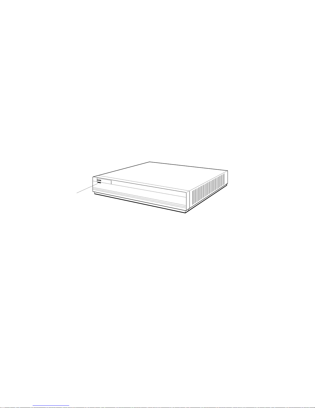
1.1.1 Front of the System Unit
The front of the system unit has a green power indicator light. The light glows
steadily when the system is operating correctly.
Figure 1–1 Front of the system unit
d
i
g
i
t
a
l
DEC station 5000
Power
indicator
light
1.1 The System Unit
WS3PO014
The Main Components and How to Install Them 1–3

The Main Components and How to Install Them
1.1 The System Unit
1.1.2 Back of the System Unit
The back of the system will appear as shown in Figure 1–2. Table 1–1 explains
each item.
Figure 1–2 Back of the system unit
2
1
0
PMAG-C
1
14
13
12
11
10
TURBOchannel option slot 0
1.
with graphics module installed
2.
TURBOchannel option slot 1
3.
TURBOchannel option slot 2
4.
Cover-release screw
5.
Monitor-to-system-unit power connector
6.
On/off switch
7.
System unit power connector
4
3
V~100-120 A 3.0
V~220-240 A 1.7
2
V~100-120/220-240
A 7.9/4.2
Hz 50-60
W 359
5
6
9
8
Keyboard-mouse connector
8.
Communications connector 2
9.
Communications connector 3
10.
Halt button
11.
12.
Diagnostic LED display
Base system ThickWire Ethernet
13.
7
connector
14.
Base system SCSI connector
1–4 The Main Components and How to Install Them
WS3PO013

The Main Components and How to Install Them
1.1 The System Unit
Table 1–1 Connectors, Controls, LED Display, and Lights on the System Unit
Item Function
TURBOchannel option slots 0, 1,
and 2
Cover-release screw A captive screw that allows the cover to be removed
Monitor-to-system-unit power
connector
On/off switch The switch that turns the system unit on and off.
System-unit power connector The point at which power from the power source
Keyboard-mouse connector The point at which the keyboard-mouse cable
Communications connectors The points at which communications devices, such
Halt button The switch that stops the worksystem software and
Diagnostic LED display Eight small red lights that indicate an error code
Base system ThickWire Ethernet
connector
Base system SCSI connector The point at which external SCSI storage devices
Power indicator light The light on the front of the system unit that
The points at which optional TURBOchannel
hardware can connect to the system unit.
from the system unit.
The point at which power can pass from the system
unit to the monitor.
Pressing the | turns the system unit on. Pressing
the O turns it off.
reaches the system unit.
connects the keyboard and mouse or tablet to the
system unit.
as modems and printers, connect to the system unit.
puts the workstation in console mode.
by means of the on-off pattern displayed when a
system failure occurs.
The point at which Ethernet network cables connect
to the system unit.
connect to the base system.
indicates whether the unit is on or off.
The Main Components and How to Install Them 1–5
The Main Components and How to Install Them
1.1 The System Unit
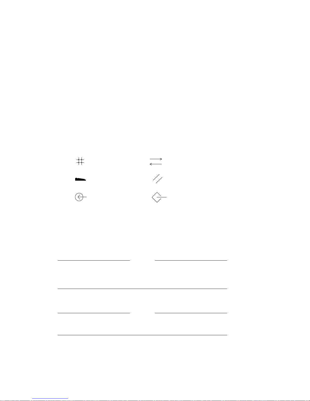
1.1.3 Icons on the System Unit
The connectors on the back of the system unit are labeled with icons to remind
you of their functions.
Figure 1–3 Icons on the system unit
Ethernet
Keyboard
Mouse
1.1.4 Setting Up the System Unit
Before setting up the system unit, check the voltage requirement labels printed
on the back of the system unit (or check for a yellow voltage label covering the
system unit power connector).
Be sure you know the voltage requirements for the device. Connecting
a device to a power source that does not meet the voltage requirements
of that device can damage the device.
1. Place the system unit flat on a level surface.
Communications
Reset button
SCSI
WS3PO015
Caution
Do not stand the system unit on its side. This blocks the cooling vents
and can damage the unit by causing it to overheat.
1–6 The Main Components and How to Install Them
Caution
The Main Components and How to Install Them
1.1 The System Unit
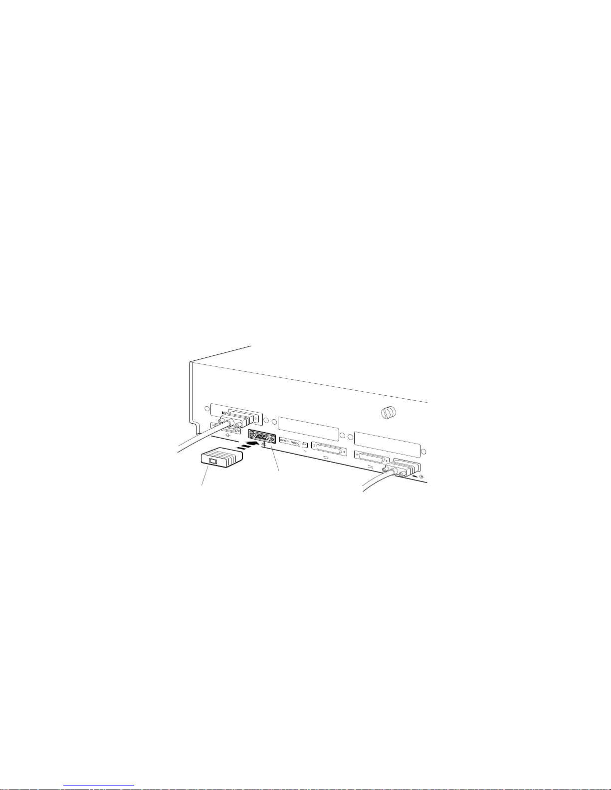
2. Install a ThickWire Ethernet loopback connector on the base system
Ethernet connector and on each Ethernet connector you may have in a
TURBOchannel option slot. Hold the loopback connector so that the widest
part of the metal rim on the connector is on top. Then firmly press the
connector onto the system unit Ethernet connector. (See Chapter 6 for
information on connecting your workstation to an Ethernet network.)
Figure 1–4 Attaching a ThickWire Ethernet loopback connector
0
PMAG-C
1
2
ThickWire Ethernet
loopback connector
3
2
Base system
ThickWire Ethernet
connector
WS3PO030
The Main Components and How to Install Them 1–7
The Main Components and How to Install Them
1.1 The System Unit
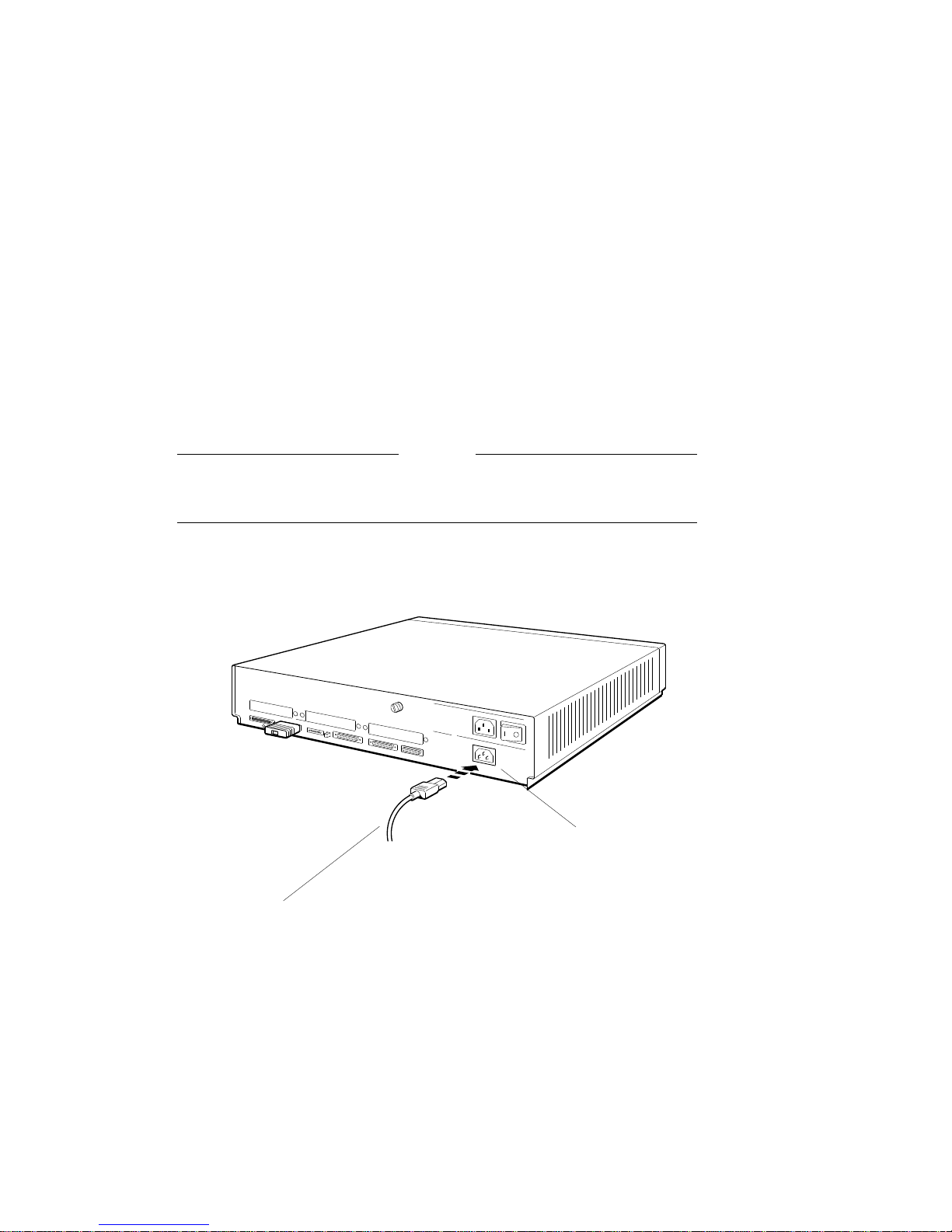
3. Connect the appropriate end of the system unit power cord to the system
unit power connector.
Do not plug the power cord into a power outlet until you have installed all
workstation components.
Caution
Installing workstation components while the system unit is connected
to a power source may damage the components if the power is on.
Figure 1–5 Connecting the power cord to the system unit
0
PMAG-C
1
V~100-120 A 3.0
V~220-240 A 1.7
2
V~100-120/2
A 7.9/4.2
Power cord
WS3PO084
1–8 The Main Components and How to Install Them
System unit
power connector

The Main Components and How to Install Them
1.2 The Monitor
Your workstation comes with a color or a monochrome monitor for use with
your worksystem software and as a system console. You can also connect
a terminal to your workstation for use as an alternate system console (see
Chapter 10 for details).
The monitors shown in the illustrations for this guide are examples of several
different monitors you can order for your workstation. The exact position of
the on/off switch, connectors, and controls will vary depending on the monitor
you order.
The video connector to which the monitor attaches can be located in any one
of the TURBOchannel option slots on the system unit, or in a TURBOchannel
extender (TCE) unit, connected to the system unit. The examples used here
assume that the video connector is in TURBOchannel option slot 0.
1.2.1 Turning Your Monitor On and Off
Before connecting the monitor, make sure that the monitor and system unit
power switches are in the off position, and that neither unit is plugged into a
power source.
1.2 The Monitor
Caution
Do not connect or disconnect your monitor while power is turned on.
This can damage the monitor.
Figure 1–6 shows how to turn the monitor power off with three different types
of switches.
The Main Components and How to Install Them 1–9

The Main Components and How to Install Them
1.2 The Monitor
Figure 1–6 Turning off your monitor
Press the 0 on
this type of switch.
Press and release this
type of switch.
Press this type
of switch so it is out.
WS3PO017
You can turn your monitor on and off independently, or install it so that it goes
on and off when you turn the main workstation power on or off (for details, see
‘‘Section 1.2.5’’). Figure 1–7 explains how to set the monitor power switch to
the on position.
Figure 1–7 Turning on your monitor
Press the I on
this type of switch.
Press and release this
type of switch.
Press this type
of switch in.
WS3PO057
1.2.2 Positioning the Monitor
Place the monitor next to or on top of the system unit if you intend to connect
its power cord to the system unit; see Section 1.2.5 for other options.
Do not place the monitor near an electromagnetic device, such as a
printer or an electric pencil sharpener, or near magnetized objects, such
as filing cabinets or steel beams in walls, which can interfere with its
performance.
1–10 The Main Components and How to Install Them
Caution

The Main Components and How to Install Them
1.2.3 Connecting the Monitor Video Cable
You connect one of the following monitor video cables to your monitor and to
the system unit.
Figure 1–8 Video cable assemblies
1.2 The Monitor
Threaded video
cable connector
3-pin connector
For a color monitor
For a monochrome monitor
RGB connectors
For a gray-scale monitor
Slotted signal
cable connector
3-pin connector
Signal cable
connector
WS3PO016
The Main Components and How to Install Them 1–11
The Main Components and How to Install Them
1.2 The Monitor
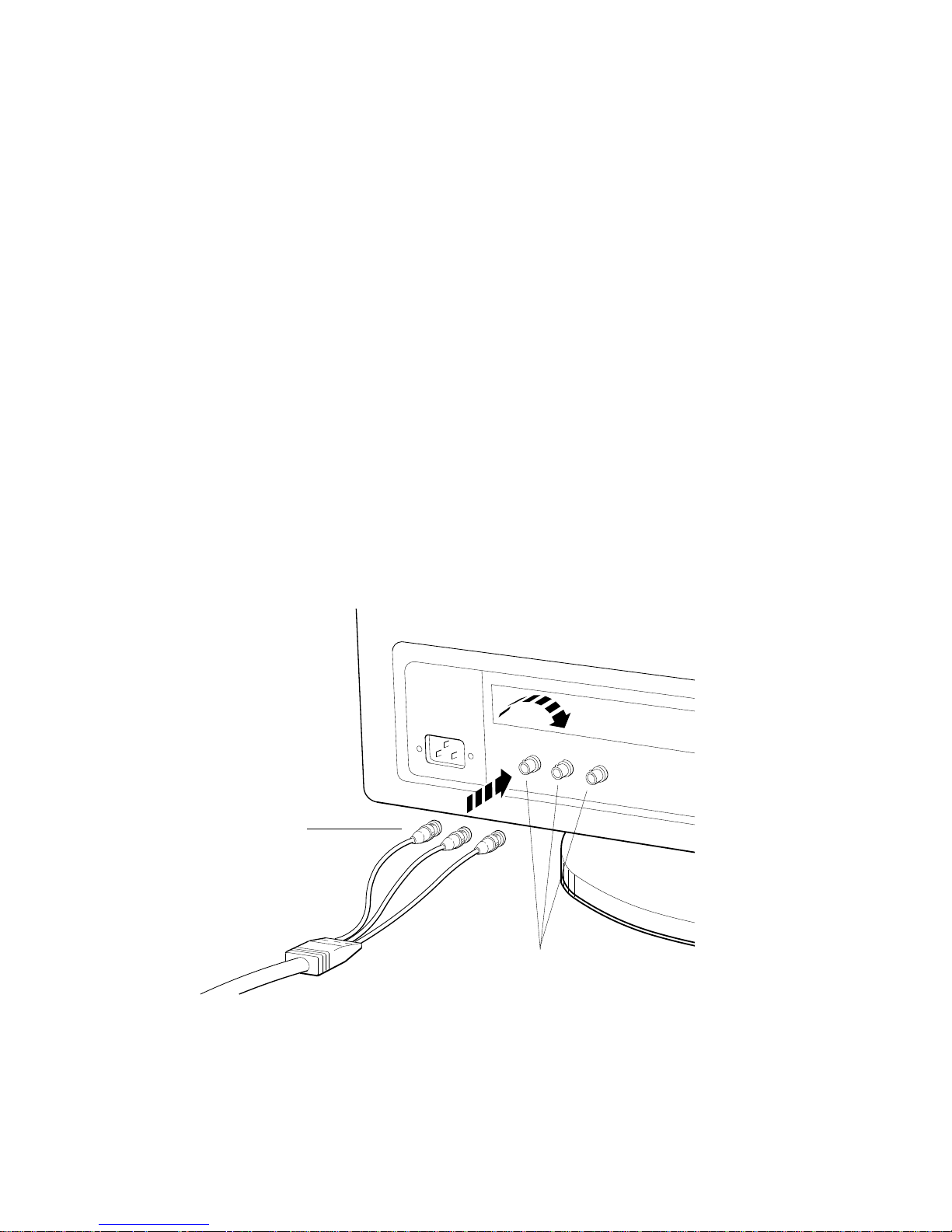
1.2.3.1 To Connect a Color Video Cable
1. The color video cable divides into red, green, and blue (RGB) cables at
one end. Match the colors of these cables with the round RGB connectors
on the monitor (labeled R, G, and B for red, green, and blue). The small
collars on the cable connectors have two slots that fit over corresponding
pins on the monitor connectors.
If your monitor has two sets of round RGB connectors, use the ones labeled
VIDEO IN. The monitor will have no display if you use the other set of
connectors.
Figure 1–9 Connecting a video cable assembly to a color monitor
Turn the signal cable
connectors to your
right until they
slide forward and
lock into place.
1–12 The Main Components and How to Install Them
R
G
Monitor video connectors
R
G
B
B
WS3PO019
The Main Components and How to Install Them
1.2 The Monitor
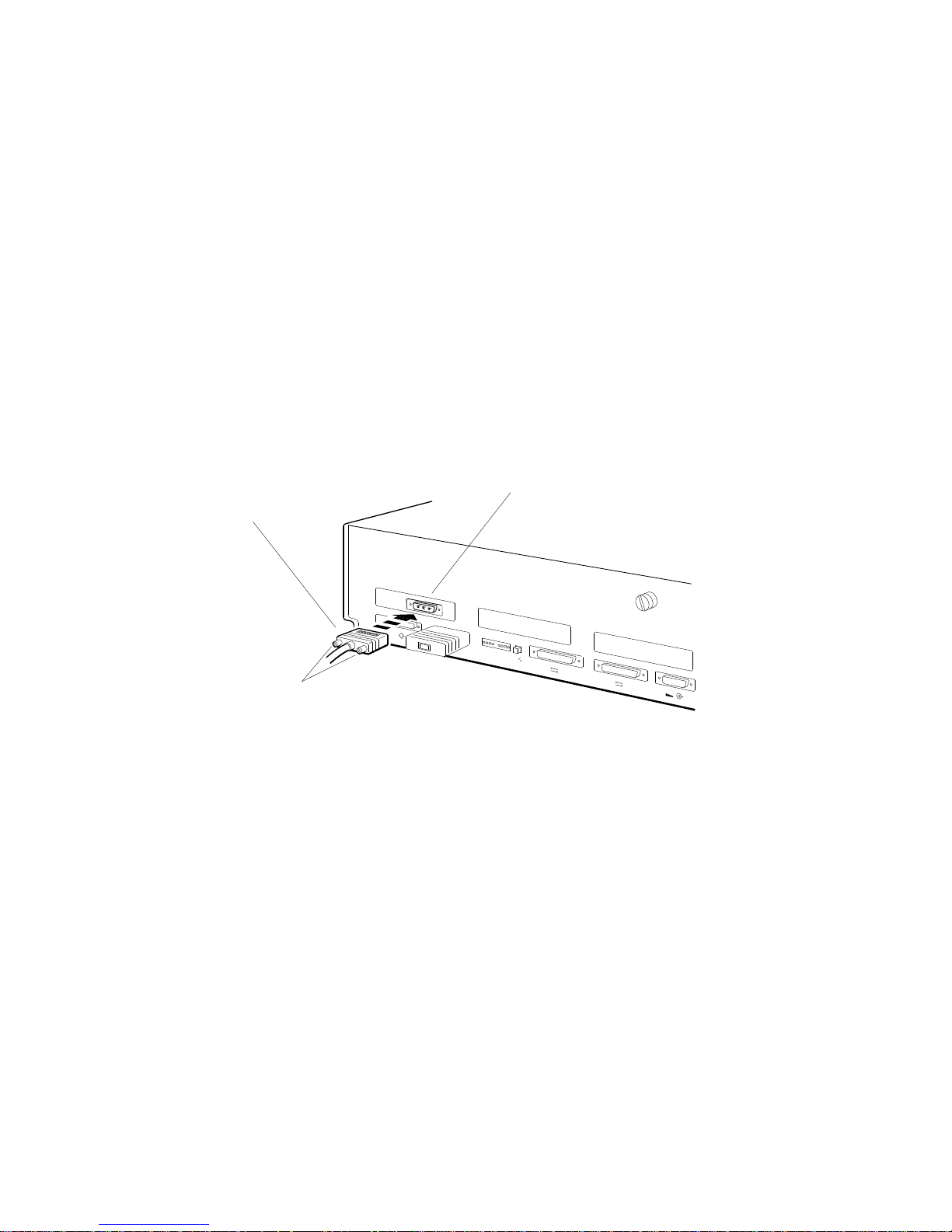
2. Connect the 3-pin cable connector to the workstation video connector in the
system unit or TCE box.
Figure 1–10 Connecting a color video cable to the system unit
1.
Position the 3-pin cable
connector so the widest
part of the connector
is on top.
Turn the screws
2.
to your right to hold
the connector in place.
PMAG-C
System unit video connector in
TURBOchannel option slot 0
0
0
1
2
3
2
WS3PO073
The Main Components and How to Install Them 1–13
The Main Components and How to Install Them
1.2 The Monitor
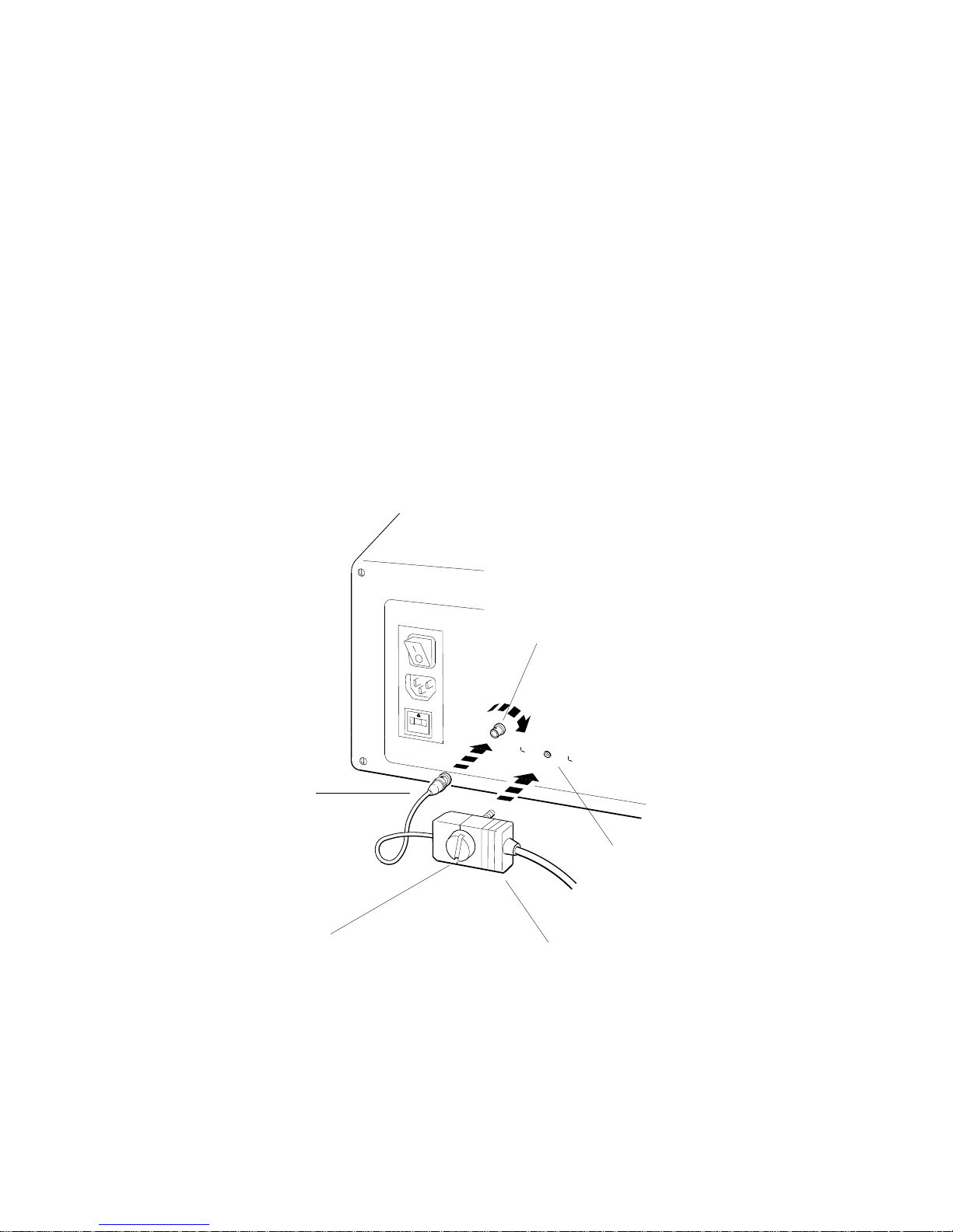
1.2.3.2 To Connect a Gray-scale Video Cable
1. Attach the round cable connector to the monitor.
2. Attach the connector block to the back of the monitor.
Figure 1–11 Connecting a video cable assembly to a gray-scale monitor
Press the round cable
1.
connector onto the
video connector
and turn the round
cable connector to
your right until it
slides forward and
locks into place.
Monitor video
connector
2.
Attach the
connector
block here.
3.
Turn the large plastic
screw to your right to
hold the connector block
in place against the monitor.
1–14 The Main Components and How to Install Them
Connector block
WS3PO020
The Main Components and How to Install Them
1.2 The Monitor
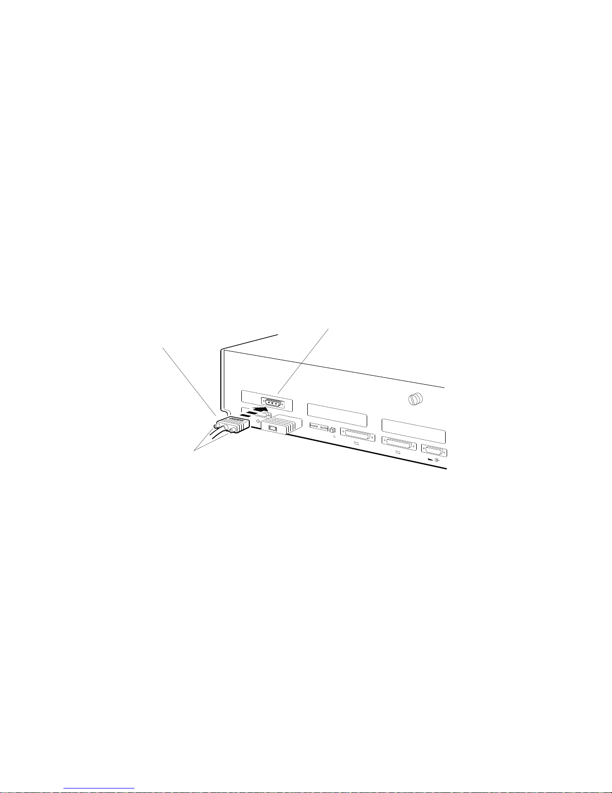
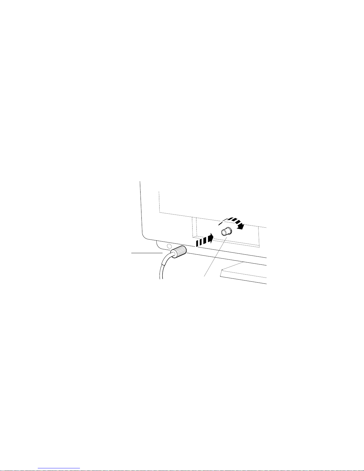
3. Attach the 3-pin cable connector to the system unit video connector in the
system unit or TCE box.
Figure 1–12 Connecting a grey-scale video cable assembly to the system
unit
1.
Position the 3-pin cable
connector so the widest
part of the connector
is on top.
Turn the screws
2.
to your right to hold
the connector in place.
PMAG-C
System unit video connector in
TURBOchannel option slot 0
0
0
1
2
3
2
WS3PO073
The Main Components and How to Install Them 1–15
The Main Components and How to Install Them
1.2 The Monitor
1.2.3.3 To Connect a Monochrome Video Cable
1. Attach the slotted cable connector to the monitor video connector.
Figure 1–13 Connecting a video cable assembly to a monochrome monitor
1. Align the slots on the
cable connector with
the pins on the monitor
video connector.
2.
Press the slotted cable
connector onto the
monitor connector and
turn the slotted cable
connector to your right
until it slides forward
and locks into place.
Monitor video
connector
WS3PO072
1–16 The Main Components and How to Install Them
 Loading...