

DECstation 5000 150 Operator's Manual

DECstation5000Model150
Operator’sGuide
Order Number: EK–4MMIN–OP. A01
Digital Equipment Corporation
Maynard, Massachusetts

First Printing, March 1993
The information in this document is subject to change without notice and should not be
construed as a commitment by Digital Equipment Corporation. Digital Equipment Corporation
assumes no responsibility for any errors that may appear in this document.
The software described in this document is furnished under a license and may be used or copied
only in accordance with the terms of such license.
All rights reserved. Printed in U.S.A.
© Digital Equipment Corporation 1993.
The postpaid Reader’s Comments forms at the end of this document request your critical
evaluation to assist in preparing future documentation.
The following are trademarks of Digital Equipment Corporation: DEC, DECconnect, DECnet,
DECstation, DECsystem, DECUS, DESTA, ThinWire, TURBOchannel, ULTRIX, ULTRIX-32, and
the DIGITAL logo.
Motif is a trademark of the Open Software Foundation, Inc. MS–DOS is a registered trademark
of Microsoft Corporation. PostScript is a registered trademark of Adobe Systems, Inc. VELCRO
is a trademark of VELCRO USA, Inc.
All other trademarks and registered trademarks are the property of their respective holders.
FCC NOTICE: This equipment has been tested and found to comply with the limits for a
Class A digital device, pursuant to Part 15 of the FCC Rules. These limits are designed to
provide reasonable protection against harmful interference when the equipment is operated in
a commercial environment. This equipment generates, uses, and can radiate radio frequency
energy and, if not installed and used in accordance with the instruction manual, may cause
harmful interference to radio communications. Operation of this equipment in a residential area
is likely to cause harmful interference, in which case the user will be required to correct the
interference at his own expense.
This document is available on CD–ROM.
This document was prepared using VAX DOCUMENT, Version 2.1.
S2084

Contents
Preface ..................................................... xiii
Part I Introducing Your Workstation
1 Getting Started
1.1 The DECstation 5000 Model 150 Workstation ............... 1–1
1.2 System Unit Components............................... 1–4
1.2.1 Connectors, Controls, and Indicator Lights on System
Unit . ........................................... 1–4
1.2.2 Icons on System Unit and Its Cables ................... 1–7
1.3 Available Options . . ................................... 1–8
2 The Environment
2.1 Site Requirements . ................................... 2–1
2.1.1 Temperature and Humidity .......................... 2–1
2.1.2 Cleanliness....................................... 2–2
2.1.3 Interference . . . ................................... 2–2
2.2 Power Requirements .................................. 2–2
3 Installing Your DECstation 5000
3.1 Connecting the Monitor ................................ 3–1
3.1.1 Connecting a Color Monitor .......................... 3–3
3.1.2 Connecting a Gray-scale Monitor . . . ................... 3–6
3.1.3 Connecting a Monochrome Monitor . ................... 3–7
3.2 Connecting the Keyboard and the Mouse or Tablet . .......... 3–9
3.3 Connecting the Dial and Button Box . . . ................... 3–12
3.4 Attaching a SCSI Terminator. ........................... 3–13
3.5 Connecting the System Unit to a Power Outlet .............. 3–15
3.6 Connecting the Monitor to a Power Outlet.................. 3–17
iii

4 Starting and Testing Workstation Hardware
4.1 Turning On Your Workstation ........................... 4–1
4.1.1 Turn On External Devices ........................... 4–2
4.1.2 Turn On the Monitor ............................... 4–3
4.1.3 Turn On the System Unit ........................... 4–4
4.1.4 Failure of System Unit to Turn On . ................... 4–5
4.2 Testing the Workstation ................................ 4–6
4.2.1 Run the System Self-Test . ........................... 4–6
4.2.2 If a Self-Test Fails ................................. 4–6
4.2.3 Check the Configuration Displays . . ................... 4–6
4.3 Stopping the Workstation Without Turning It Off . . .......... 4–7
4.4 Turning Off the Workstation . ........................... 4–8
4.5 Installing Workstation Software ......................... 4–8
5 Moving Your Workstation
5.1 Dismantling the Workstation . ........................... 5–1
5.2 Packing the Equipment ................................ 5–2
Part II External Additions to Your Workstation
6 Connecting Your System to a Network
6.1 Connecting a ThickWire Ethernet Cable ................... 6–1
6.2 Connecting a ThinWire Ethernet Cable . ................... 6–5
6.3 Connecting a Twisted-Pair Ethernet Cable ................. 6–9
7 Connecting External Options
7.1 Setting Up Storage Expansion Boxes and Cables. . . .......... 7–1
7.2 Connecting the Expansion Box to the System Unit . .......... 7–3
7.3 Connecting to One Expansion Box ........................ 7–6
7.4 Connecting to Multiple Expansion Boxes................... 7–9
7.5 Connecting Communication Devices....................... 7–11
7.5.1 To Connect a Device with a 25-Pin Connector . . .......... 7–11
7.5.2 To Connect a Device with a Telephone-Jack Type of
Connector ....................................... 7–13
iv

8 The Server Configuration
8.1 Installing a Terminal as an Alternate System Console ........ 8–1
8.1.1 To Install a Terminal as a System Console .............. 8–2
8.1.2 To Activate the Terminal as the System Console .......... 8–4
8.1.3 To Make Your Workstation Monitor the System Console . . . . 8–5
Part III Internal Additions to Your Workstation
9 Opening and Closing the System Unit
9.1 Removing the System Unit Cover ........................ 9–1
9.2 Attaching the Antistatic Wrist Strap . . . ................... 9–3
9.3 Removing the Front Drive Panel ......................... 9–4
9.4 Replacing the Front Drive Panel ......................... 9–6
9.5 Replacing the System Unit Cover ........................ 9–8
10 Installing and Removing Memory Modules
10.1 Memory Configurations ................................ 10–1
10.2 Installing Memory Modules . . ........................... 10–1
10.3 Testing Memory Modules ............................... 10–5
10.4 Removing Memory Modules . . ........................... 10–5
11 Installing and Removing Drives in the System Unit
11.1 Preparing for an Installation . ........................... 11–3
11.2 Setting SCSI ID Numbers . . . ........................... 11–4
11.3 Installing a Hard Disk Drive . ........................... 11–15
11.4 Testing a Hard Disk Drive Installation . ................... 11–22
11.5 Removing a Hard Disk Drive . ........................... 11–23
11.6 Installing a Removable Media Drive . . . ................... 11–23
11.7 Testing a Removable Media Drive Installation ............... 11–29
11.8 Removing a Drive from the Front Drive Panel ............... 11–29
12 Removing and Replacing the CPU Module
12.1 Removing CPU Modules................................ 12–1
12.2 Replacing a CPU Module ............................... 12–3
12.3 Testing the CPU Module ............................... 12–6
v

Part IV Workstation Management
13 Using the Console Program
13.1 Operating and Console Modes ........................... 13–1
13.2 Entering Console Mode ................................ 13–2
13.3 Console Command Conventions and Terms ................. 13–3
13.3.1 Console Command Conventions Used .................. 13–4
13.3.2 Definition of Terms ................................ 13–4
13.4 Summary of Console Commands ......................... 13–6
13.4.1 ? Command . . . ................................... 13–7
13.4.2 boot Command . ................................... 13–7
13.4.3 cat Command . . ................................... 13–9
13.4.4 cnfg Command . ................................... 13–9
13.4.5 d Command . . . ................................... 13–11
13.4.6 erl Command . . ................................... 13–12
13.4.7 go Command . . ................................... 13–13
13.4.8 init Command . ................................... 13–13
13.4.9 ls Command . . . ................................... 13–13
13.4.10 passwd Command ................................. 13–14
13.4.11 printenv Command ................................ 13–14
13.4.12 restart Command .................................. 13–15
13.4.13 script Command ................................... 13–15
13.4.14 setenv Command .................................. 13–15
13.4.15 sh Command . . ................................... 13–17
13.4.16 t Command . . . ................................... 13–18
13.4.17 test Command . ................................... 13–18
13.4.18 unsetenv Command ................................ 13–18
14 Troubleshooting
14.1 Where to Look for Troubleshooting Information.............. 14–1
14.2 Checking the Diagnostic Lights .......................... 14–2
14.3 Solving Common Problems. . . ........................... 14–4
14.4 Running a Self-Test ................................... 14–12
14.5 Interpreting Self-Test Messages .......................... 14–13
14.6 Contacting Your Digital Service Representative .............. 14–18
vi

Part V Appendixes
A Regulatory Information for the UK
A.1 Service Requirements ................................. A–2
A.2 Approvals for Digital Circuits ........................... A–2
A.3 Host Independent Approvals . ........................... A–3
A.4 Host Power Rating . ................................... A–4
A.5 Environmental Conditions . . . ........................... A–4
A.6 Apparatus Between the Approved Apparatus and a Digital
Circuit (PTT) ........................................ A–4
B Equipment Specifications
B.1 DECstation 5000 Model 150 System Unit .................. B–2
B.2 RZ23L Hard Disk Drive ................................ B–3
B.3 RZ24L Hard Disk Drive ................................ B–5
B.4 RZ25 Hard Disk Drive ................................. B–6
B.5 RZ26 Hard Disk Drive ................................. B–7
B.6 RX23 Diskette Drive .................................. B–9
B.7 RRD42 Compact Disc Drive . . ........................... B–10
B.8 TZK10 Tape Drive . ................................... B–11
B.9 TLZ06 Tape Drive . ................................... B–14
C Connector Pin Assignments
C.1 SCSI Connector . . . ................................... C–1
C.2 ThickWire Ethernet Connector........................... C–3
C.3 EIA RS232 Communications Connectors ................... C–4
C.4 Power Supply ........................................ C–5
C.5 Loopback Connector .................................. C–6
Index
vii

Figures
1–1 Typical DECstation 5000 Workstation .................. 1–2
1–2 Workstation Components . ........................... 1–3
1–3 Back of System Unit ............................... 1–5
1–4 Icons on the Workstation . ........................... 1–7
2–1 Voltage Labels . ................................... 2–3
3–1 Video Cable Assemblies . . ........................... 3–2
3–2 Turning Off the Monitor. . ........................... 3–3
3–3 Connecting Color or Gray-Scale Video Cable to System
Unit . ........................................... 3–4
3–4 Connecting a Video Cable Assembly to a Color Monitor . . . . . 3–5
3–5 Connecting Video Cable Assembly to 19-Inch Gray-Scale
Monitor ......................................... 3–6
3–6 Connecting Video Cable Assembly to Monochrome
Monitor ......................................... 3–8
3–7 Connecting the Keyboard and Mouse ................... 3–9
3–8 Attaching the Keyboard-Mouse Cable Connector .......... 3–10
3–9 Hinged Feet on the Keyboard ........................ 3–11
3–10 Dial and Button Box ............................... 3–12
3–11 Attaching a Terminator to the System SCSI Connector . . . . . 3–14
3–12 Connecting the Power Cord to the System Unit . .......... 3–16
3–13 Connecting the Monitor to the System Unit.............. 3–18
4–1 Expansion Box On/Off Switches ....................... 4–2
4–2 Turning on the Monitor . . ........................... 4–3
4–3 Turning on the System Unit ......................... 4–4
4–4 Halt Button and System Unit On/Off Switch . . . .......... 4–7
6–1 ThickWire Ethernet Cable ........................... 6–1
6–2 Sliding Lock on ThickWire Ethernet Connector . .......... 6–2
6–3 Attaching the ThickWire Ethernet Cable to the System
Unit . ........................................... 6–3
6–4 Sliding Lock on System Unit ThickWire Ethernet
Connector ........................................ 6–4
6–5 Parts Used to Connect a ThinWire Network . . . .......... 6–5
6–6 Connecting a ThickWire cable to the ThinWire Adapter . . . . 6–6
6–7 Attaching a T-connector . . ........................... 6–7
6–8 Attaching a T-connector Terminator . ................... 6–8
6–9 Twisted-Pair Ethernet Cables and Adapter .............. 6–9
viii

6–10 Attaching the Twisted-pair Ethernet Cable to the
Adapter ......................................... 6–10
6–11 Attaching the ThickWire Ethernet Cable to the Adapter and
System Unit . . . ................................... 6–11
7–1 System-Unit-to-Expansion-Box Cable................... 7–3
7–2 Removing the SCSI Terminator ....................... 7–4
7–3 Connecting the System-Unit-to-Expansion-Box Cable to the
System Unit . . . ................................... 7–5
7–4 Connecting the System-Unit-to-Expansion-Box Cable to the
Expansion Box . ................................... 7–7
7–5 Connecting the Expansion Box Power Cord .............. 7–8
7–6 Connecting Multiple Expansion Boxes .................. 7–9
7–7 Attaching the SCSI Terminator to the Last Expansion
Box............................................. 7–10
7–8 Communication Device Adapter and Connectors .......... 7–11
7–9 Connecting a 25-pin Connector ....................... 7–12
7–10 Using an Adapter to Connect a Communications Device to
the System Unit ................................... 7–13
8–1 Connecting a VT320 Terminal to the System Unit ......... 8–3
9–1 Removing the Cover From the System Unit.............. 9–2
9–2 Using an Antistatic Wrist Strap....................... 9–3
9–3 Inside the System Unit . . ........................... 9–4
9–4 Removing the Front Drive Panel . . . ................... 9–5
9–5 Replacing the Front Drive Panel . . . ................... 9–7
9–6 Replacing the Cover on the System Unit ................ 9–8
10–1 Memory Slots Inside the System Unit .................. 10–2
10–2 Memory Module ................................... 10–3
10–3 Inserting a Memory Module .......................... 10–4
10–4 Memory Modules in Memory Slots 0 and 1 .............. 10–6
10–5 Removing a Memory Module ......................... 10–7
11–1 Where to Install Drives in the System Unit .............. 11–2
11–2 Jumper Settings for an RZ23L Hard Disk Drive .......... 11–6
11–3 Jumper Settings for the RZ24L Hard Disk Drive .......... 11–7
11–4 Jumper Settings Using the Pins on the Front of the RZ25
Drive ........................................... 11–9
11–5 Jumper Settings Using the Pins on the Side of the RZ25
Drive ........................................... 11–10
11–6 Jumper Settings for an RZ26 Hard Disk Drive . .......... 11–11
ix

11–7 Jumper Settings for an RRD42 Optical Compact Disc
drive. ........................................... 11–12
11–8 Switch Settings for RX23 and RX33 Floppy Disk Drives . . . . 11–13
11–9 TLZ06 Mode and SCSI Address Switches ............... 11–14
11–10 Jumper Settings for a TZK10 QIC Tape Drive . . .......... 11–15
11–11 Locations for Internal Hard Disk Drives ................ 11–16
11–12 Power Supply Cable in the System Unit ................ 11–17
11–13 SCSI Cable in the System Unit ....................... 11–18
11–14 Power Supply Cable Connector ....................... 11–19
11–15 SCSI Connector ................................... 11–20
11–16 Inserting the Hard Disk Drive ........................ 11–21
11–17 Inserting a Removable Media Drive into the Drive
Bracket ......................................... 11–24
11–18 SCSI Cable Connector . . . ........................... 11–25
11–19 Plugging the Cable Straight into the Connector . .......... 11–26
11–20 Removing the Existing Bezel ......................... 11–27
11–21 Installing a New Bezel . . . ........................... 11–28
12–1 CPU Module . . . ................................... 12–2
12–2 R4000 CPU Module Switch Packet Settings . . . .......... 12–3
12–3 Installing a CPU Module . ........................... 12–4
12–4 Removing the Nameplate . ........................... 12–5
12–5 Attaching the Product Conversion Label ................ 12–6
14–1 Diagnostic Indicator Lights .......................... 14–2
Tables
1 Conventions Used in This Guide . . . ................... xiii
1–1 Connectors, Controls, and Indicator Lights on System
Unit . ........................................... 1–6
1–2 DECstation 5000 Model 150 Devices and Options ......... 1–8
7–1 Expansion Box Cables . . . ........................... 7–2
11–1 Default SCSI ID Numbers for Internal Drives . . .......... 11–4
13–1 Console Commands ................................ 13–6
13–2 Module Codes . . ................................... 13–11
13–3 SCSI Device Codes ................................. 13–11
13–4 Environment Variables. . . ........................... 13–16
14–1 Interpreting Diagnostic Indicator Lights ................ 14–3
x

14–2 Solutions to Common Problems ....................... 14–4
14–3 Self-Test Error Messages for the Base System Slot ........ 14–14
A–1 PMBA-AA Service Requirements . . . ................... A–2
A–2 Clearance and Creepage Specs for PMBA-AA . . .......... A–3
A–3 Module Power Rating for PMBA-AA ................... A–4
B–1 System Unit Description . ........................... B–2
B–2 System Unit Operating Conditions . ................... B–2
B–3 System Unit Nonoperating Conditions .................. B–2
B–4 Acoustics—Preliminary Declared Values per ISO 9296 and
ISO 7779 ........................................ B–3
B–5 RZ23L Hard Disk Drive Description ................... B–3
B–6 RZ23L Hard Disk Drive Operating Conditions . .......... B–4
B–7 RZ23L Hard Disk Drive Nonoperating Conditions ......... B–4
B–8 RZ24L Hard Disk Drive Description ................... B–5
B–9 RZ24L Hard Disk Drive Operating Conditions . .......... B–5
B–10 RZ24L Hard Disk Drive Nonoperating Conditions ......... B–5
B–11 RZ25 Hard Disk Drive Description . ................... B–6
B–12 RZ25 Hard Disk Drive Operating Conditions . . . .......... B–7
B–13 RZ25 Hard Disk Drive Nonoperating Conditions .......... B–7
B–14 RZ26 Hard Disk Drive Description . ................... B–7
B–15 RZ26 Drive Operating Conditions . . ................... B–8
B–16 RZ26 Drive Nonoperating Conditions ................... B–8
B–17 RX23 Diskette Disk Drive Description .................. B–9
B–18 RX23 Diskette Drive Operating Conditions .............. B–9
B–19 RX23 Diskette Drive Nonoperating Conditions . .......... B–10
B–20 RRD42 Compact Disc Drive Description ................ B–10
B–21 RRD42 Compact Disc Drive Operating Conditions ......... B–11
B–22 RRD42 Compact Disc Drive Nonoperating Conditions ...... B–11
B–23 TZK10 Cartridge Tape Drive Description ................ B–11
B–24 TZK10 Operating Conditions ......................... B–12
B–25 TZK10 Nonoperating Conditions . . . ................... B–13
B–26 TLZ06 Drive Description . ........................... B–14
B–27 TLZ06 Drive Operating Conditions . ................... B–14
B–28 TLZ06 Drive Nonoperating Conditions .................. B–14
B–29 TLZ06 Cassettes .................................. B–14
C–1 SCSI Connector Pin Assignments . . ................... C–2
C–2 ThickWire Ethernet Connector Pin Assignments .......... C–3
xi

C–3 EIA RS232 Communications Connectors Pin Assignments . . . C–4
C–4 Power Supply Pin Assignments ....................... C–5
C–5 Summary of Loopback Connectors . . ................... C–6
C–6 Ethernet Loopback Connector ........................ C–6
C–7 Modem Loopback Connector ......................... C–6
xii

Preface
This guide explains how to install and test the hardware components of your
DECstation 5000 Model 150 workstation. It also describes how to use your
system as a server.
Table 1 Conventions Used in This Guide
Convention Use
Monospace type
Boldface type Anything that you are asked to type is set in boldface type.
Caution Caution notes provide information that protects your
italic type Indicates a variable or a complete title of a manual.
Anything that appears on your monitor screen is set in
monospace type.
workstation from being damaged.
xiii


PartI
Introducing Your Workstation


Getting Started
This chapter provides an overview of the following topics:
• The DECstation 5000 Model 150 Workstation
• System Unit Components
• Available Options
1.1 The DECstation 5000 Model 150 Workstation
The DECstation 5000 Model 150 workstation features:
• 50 SPECmarks
• Graphics, storage, and expansion options
• On-chip cache of 8 KB instruction and 8 KB data
• 1 MB secondary cache
Figure 1–1 shows a typical DECstation 5000.
1
Getting Started 1–1
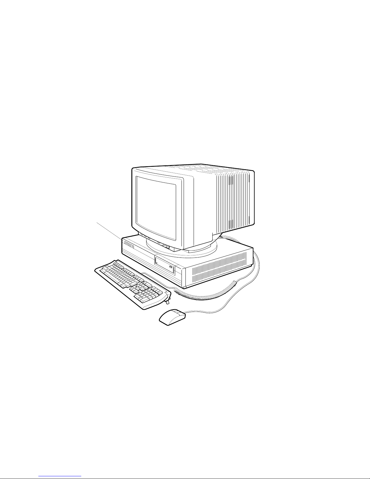
1.1 The DECstation 5000 Model 150 Workstation
Figure 1–1 Typical DECstation 5000 Workstation
Nameplate
d i g i t a l
In addition to the this manual, you should have the following:
• Any options you ordered
• Any software you ordered
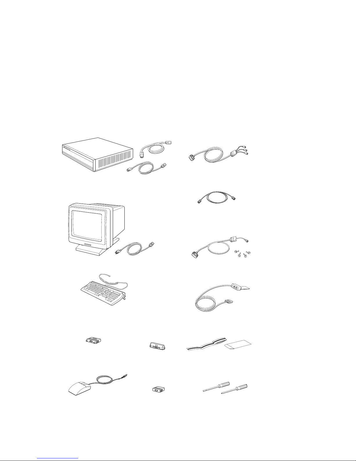
• All the items shown in Figure 1–2, except only one type of video cable
assembly: color, monochrome, or gray-scale.
1–2 Getting Started
WS33O137
1.1 The DECstation 5000 Model 150 Workstation
Figure 1–2 Workstation Components
System unit, power cord, and
monitor-to-system-unit power cable
Color video cable assembly
Monochrome video cable assembly
Monitor and monitor power cord
Keyboard with cable
(Keyboard ordered may
vary from the one shown)
Communication
connector adapter
Mouse with cable
WS33O131
SCSI terminator
ThickWire Ethernet
loopback connector
Gray-scale video cable assembly
Keyboard-mouse cable assembly
Antistatic wrist strap
Screwdrivers
Getting Started 1–3

1.2 System Unit Components
1.2 System Unit Components
The system unit sits flat on a level surface with the monitor on top of or next
to it.
Caution
Do not stand the system unit on its side. This can block the cooling
vents and damage the unit.
1.2.1 Connectors, Controls, and Indicator Lights on System Unit
Figure 1–3 shows the connectors and switches on the back of the system unit.
Table 1–1 explains each item.
1–4 Getting Started
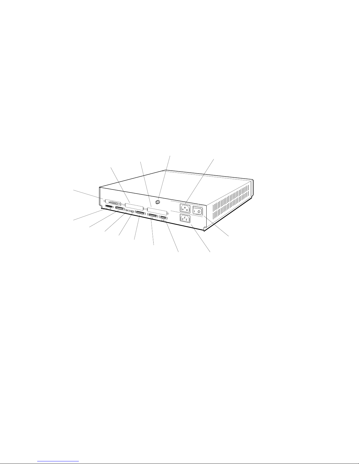
Figure 1–3 Back of System Unit
1.2 System Unit Components
2
1
PMAG-C
14
13
12
11
10
1.
TURBOchannel option slot 0.
2.
TURBOchannel option slot 1
3.
TURBOchannel option slot 2
4.
Cover-release screw
5.
Monitor-to-system-unit power connector
6.
On/off switch
7.
System unit power connector
8.
Keyboard-mouse connector
4
3
V~100-120 A 3.0
V~220-240 A 1.7
V~100-120/220-240
A 7.9/4.2
Hz 50-60
W 359
2
5
6
9
8
9.
Communications connector 2
10.
Communications connector 3
11.
Halt button
12.
Diagnostic indicator lights
13.
Base system ThickWire Ethernet
7
connector
14.
Base system SCSI connector
WS33O094
Getting Started 1–5

1.2 System Unit Components
Table 1–1 Connectors, Controls, and Indicator Lights on System Unit
Item Function
TURBOchannel option slots 0, 1,
and 2
Cover-release screw A captive screw that allows the cover to be removed
Monitor-to-system-unit power
connector
On/Off switch The switch that turns the system unit on and off.
System unit power connector The point at which power from the power source
Keyboard-mouse connector The point at which the keyboard-mouse cable
Communications connectors The points at which communications devices, such
Halt button The switch that stops the worksystem software and
Diagnostic indicator lights Lights that indicate where system failures occurred;
Base system ThickWire Ethernet
connector
Base system SCSI connector The point at which external small computer system
The points at which optional TURBOchannel
hardware can connect to the system unit. (In
Figure 1–3, TURBOchannel slot 0 contains a video
connector, the point at which a video cable connects
the monitor to the system unit.)
from the system unit.
The point at which power can pass from the system
unit to the monitor.
Pressing (|) turns the system unit on; pressing (O)
turns it off.
reaches the system unit.
connects the keyboard and mouse or tablet to the
system unit.
as modems and printers, connect to the system unit.
puts the workstation in console mode.
useful when there is no display on the monitor.
The point at which Ethernet network cables connect
to the system unit.
interface (SCSI) storage devices connect to the base
system.
1–6 Getting Started

1.2.2 Icons on System Unit and Its Cables
Many of your workstation connectors and cables use icons to remind you of
their functions. Figure 1–4 shows the icons used on your workstation system
unit.
Figure 1–4 Icons on the Workstation
1.2 System Unit Components
Ethernet
Keyboard
Mouse
Communications
Reset button
SCSI
WSE2O003
Getting Started 1–7

1.3 Available Options
1.3 Available Options
Table 1–2 lists the internal and external options for the DECstation 5000
Model 150. Internal options must be installed inside the system unit or in an
expansion box. External options, including expansion boxes and peripheral
devices such as printers and modems, can be attached by a cable to the system
unit.
An ‘‘X’’ in Table 1–2 indicates where the option can be installed; in the system
unit, an expansion box, or both.
Table 1–2 DECstation 5000 Model 150 Devices and Options
Option System Unit
RZ23L, RZ24L, RZ25, RZ26 hard disk drives X X
RZ58 hard disk drive X
RRD42, RX23, TLZ06, TZK10 drives X X
RX33, TK50, TKZ08, TZ30 drives X
MS01–AA, MS01–CA, MS01L–AB memory modules X
TURBOchannel Graphics X X
Expansion
Box
1–8 Getting Started

This chapter describes the following topics:
• Site Requirements
• Power Requirements
2.1 Site Requirements
To operate at its best, your workstation must be set up in a place that meets
certain requirements.
Failure to meet these requirements can damage the equipment.
2.1.1 Temperature and Humidity
• The temperature around the workstation should be between 50° F (10° C)
and 95° F (35° C).
The workstation should be set up away from heaters, photocopiers, and
other sources of heat.
Protect your workstation from direct sunlight.
2
The Environment
Caution
The Environment 2–1

2.1 Site Requirements
• Air should flow freely around your workstation to keep heat from building
up and damaging the equipment.
Leave 4 inches (10 centimeters) between system unit vents and other
objects.
Leave 3 inches (7.6 centimeters) between monitor vents and other objects.
• Relative humidity should be between 10 and 90 percent.
• Store supplies (such as tape cartridges) within these same temperature and
humidity limits.
2.1.2 Cleanliness
• Keep your work area as dust-free as possible.
2.1.3 Interference
• Set up your workstation at least 30 inches (76.2 centimeters) from any
sources of electrical interference, such as other terminals or monitors,
printers, or electric pencil sharpeners.
• To limit its exposure to static electricity and magnetized objects, set up
your workstation away from busy corridors and other high-traffic areas and
away from filing cabinets and steel beams in walls.
2.2 Power Requirements
• Reserve an entire circuit for your workstation power source. The fuse for
the circuit must be at least 20 amperes.
• Be sure your electrical circuit is properly grounded and free from electrical
noise. If possible, connect a surge-protected power strip to the outlet and
plug your workstation power cord into the power strip.
Many of the devices you connect to your workstation, including most monitors,
must have voltages that match your power source, which is either 110/120 or
220/240 volts. Devices that require matching voltages have a yellow voltage
label covering the power connector. This label tells you that device’s power
requirements. (See Figure 2–1.)
Connecting your equipment to a power source with the wrong voltage
can damage the equipment.
2–2 The Environment
Caution
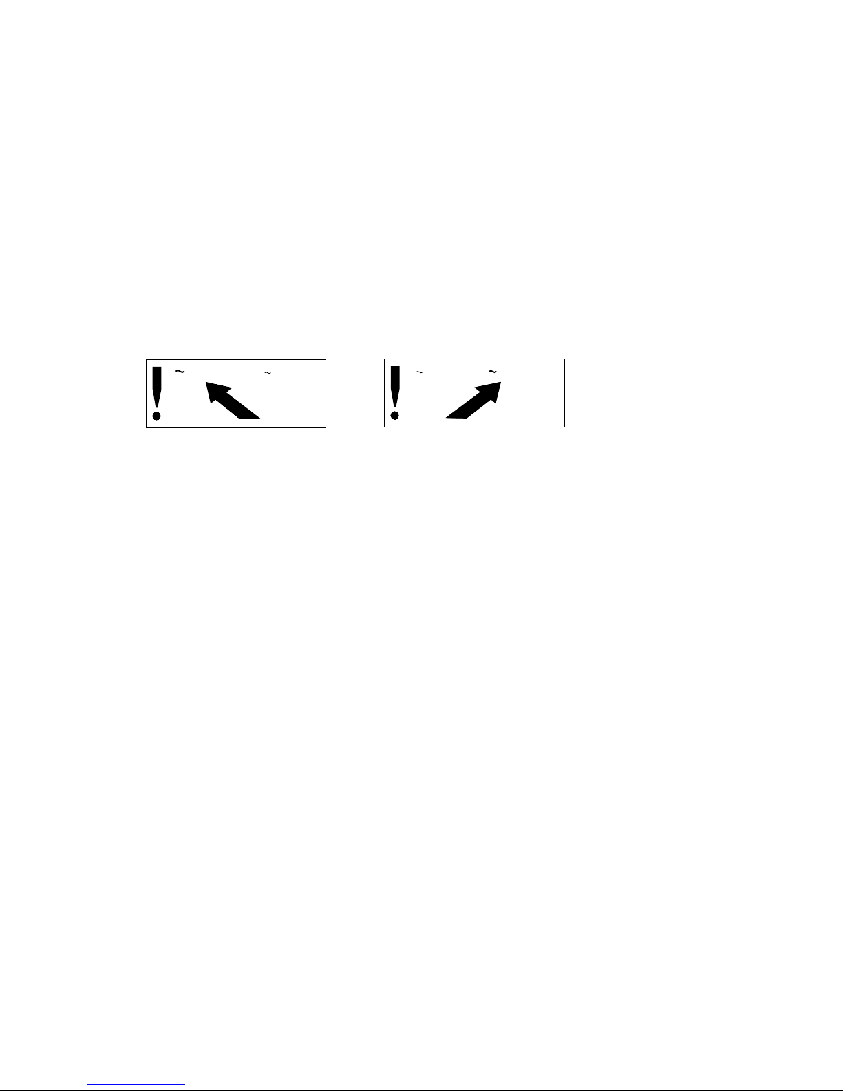
Figure 2–1 Voltage Labels
2.2 Power Requirements
V 100-120
V 220-240
36-17905-19
V 100-120
V 220-240
36-17905-19
WSE2I021
The Environment 2–3


Installing Your DECstation 5000
This chapter explains the following installation steps:
• Connecting the Monitor
• Connecting the Keyboard and the Mouse or Tablet
• Connecting the Dial and Button Box
• Attaching a SCSI Terminator
• Connecting the System Unit to a Power Outlet
• Connecting the Monitor to a Power Outlet
3.1 Connecting the Monitor
Make sure that both the monitor and system unit are turned off.
Connecting or disconnecting your monitor while power is turned on can
damage the monitor.
3
Caution
1. Select the appropriate video cable assembly for your workstation. (See
Figure 3–1.)
• The video cable assembly for a color monitor has a set of red, green,
and blue (RGB) signal cables at one end and a 3-pin connector at the
other.
• The video cable assembly for a gray-scale monitor has a round signal
cable connector at one end and a 3-pin connector at the other end.
• The video cable assembly for a monochrome monitor has a threaded
video cable connector on one end and a slotted connector on the other
end.
Installing Your DECstation 5000 3–1

3.1 Connecting the Monitor
Figure 3–1 Video Cable Assemblies
Threaded video
cable connector
3-pin connector
For a color monitor
For a monochrome monitor
RGB connectors
For a gray-scale monitor
Slotted signal
cable connector
3-pin connector
Signal cable
connector
WS33O040
3–2 Installing Your DECstation 5000
 Loading...