

DECstation 200 Hardware Installation Manual

dt
DECstation 5000 Model 200
Hardware Installation Guide
EK-365AA-IN-002
i
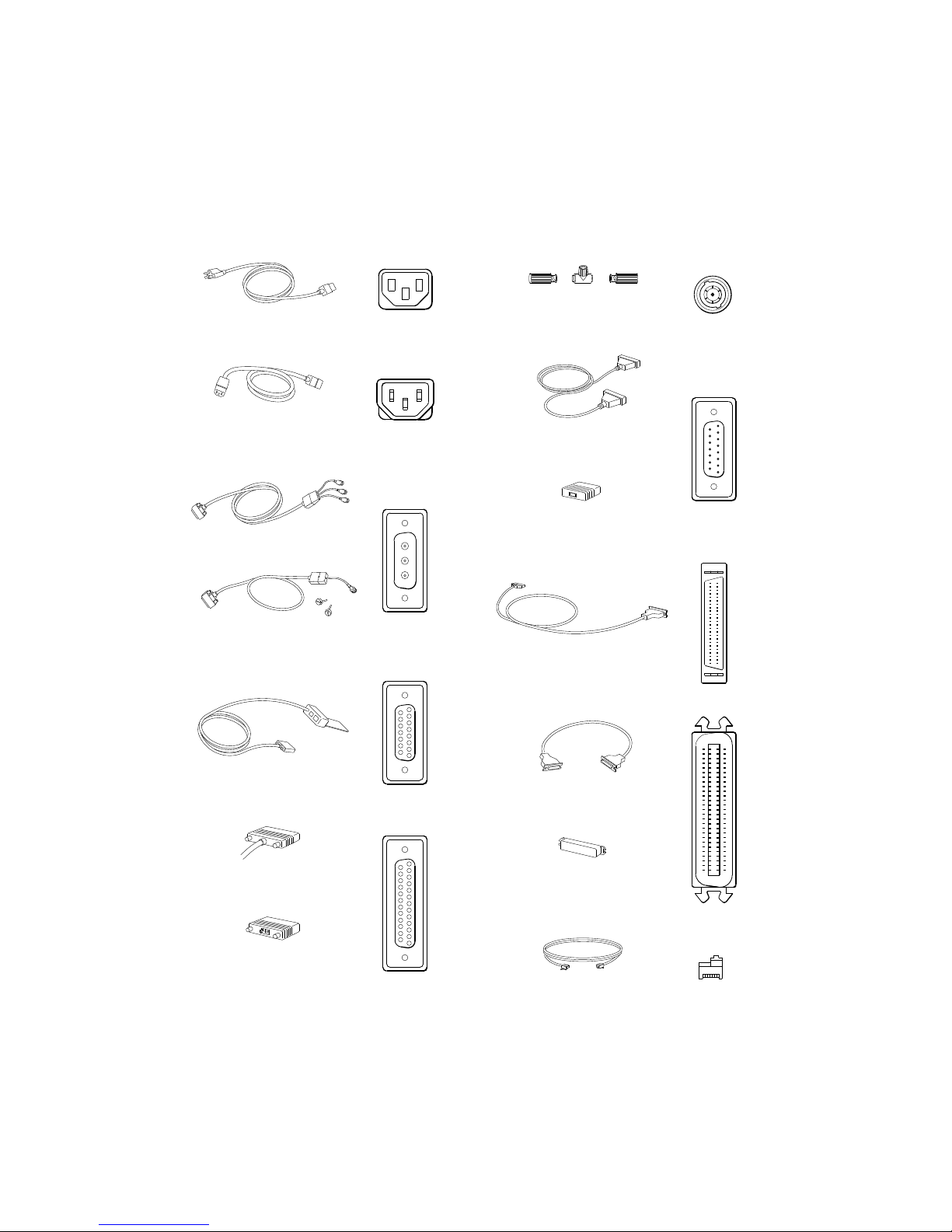
Cords, cables, terminators, adapters, and connectors on the
system unit and expansion boxes
ThinWire T-connector
Power cord
with two ThinWire terminators
Monitor-to-system-unit
power cable
Color video cable assembly
Gray scale
video cable assembly
Keyboard-mouse cable
Communication device
cable connector
ThickWire
Ethernet cable
ThickWire Ethernet
loopback connector
System-unit-toexpansion-box cable
18-inch box-to-box
expansion cable
Expansion-box
terminator
Communications
connector adapter
WSE2O041
ii
Serial cable
for console terminal
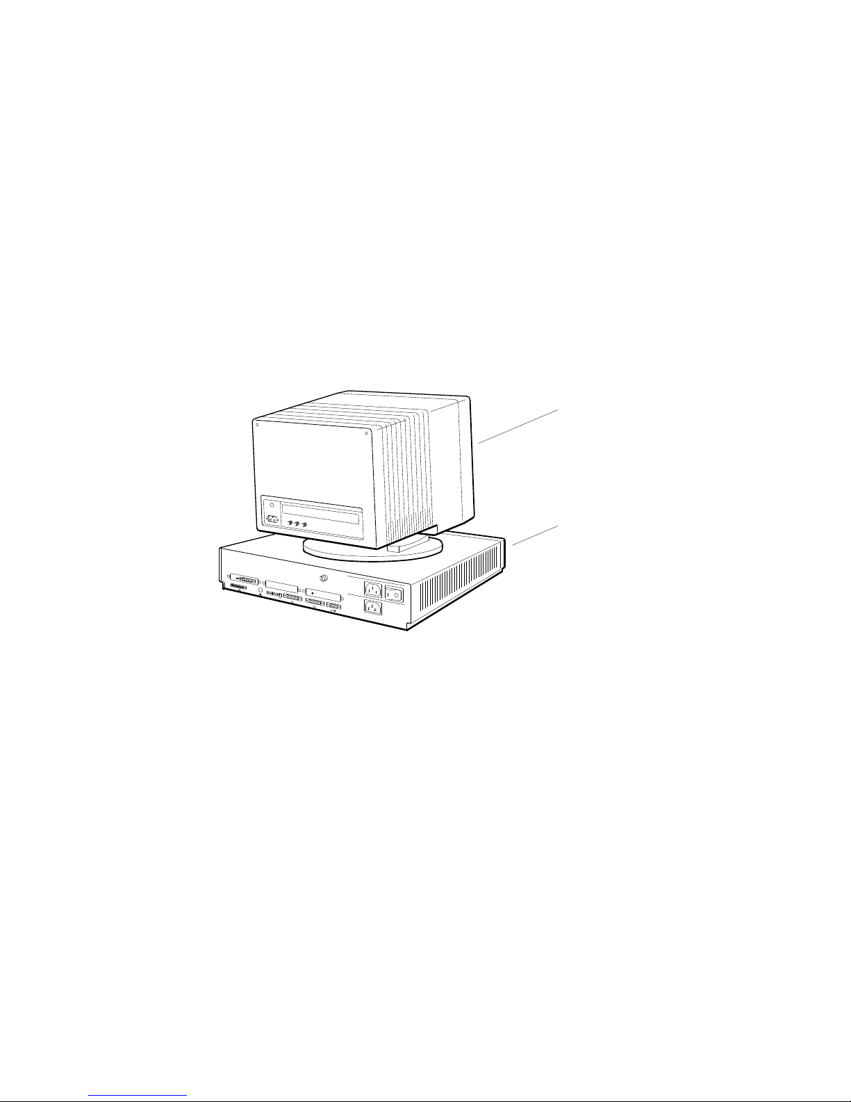
Set up the system unit and monitor.
Warning: It takes two people to unpack the monitor, system unit, and
BA42 storage expansion box safely.
Cautions: Placing the system unit on its side blocks air vents and
causes the unit to overheat.
Placing the monitor near electromagnetic devices, such as printers or
electric pencil sharpeners, or near magnetized objects, such as filing
cabinets or steel beams in walls, can interfere with its performance.
R
G
B
0
PMAG-C
1
3
V~100-120 A 3.0
V~220-240 A 1.7
2
PMAD-A
V~100-120/220-240
A 7.9/4.2
Hz 50-60
W 359
2
Monitor
System unit
WSE2I090
1
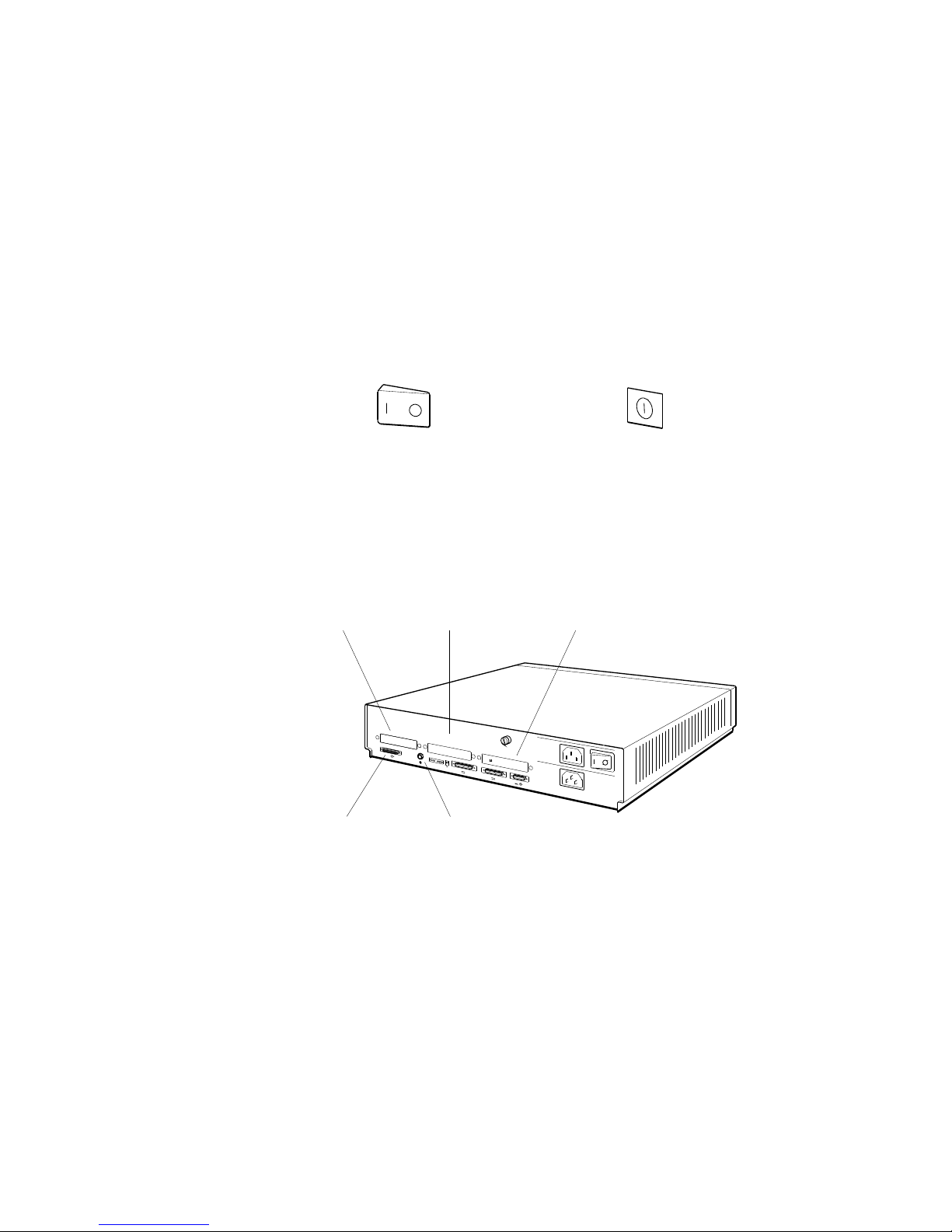
Be sure the on/off switches on the system unit and monitor are
in the off position.
Press the 0 on the on/off switch on the system unit, the 19-inch
VRT19 color monitor, the 16-inch VR297 color monitor, and the
VR262 gray scale monitor. Press and release the on/off switch
on the 19-inch VR299 color monitor.
Press the 0 on
this type of switch.
Press and release this
type of switch.
Familiarize yourself with base system slots 5 and 6 and with
the three option slots on the back of the system unit.
Option slot 0
Base system slot 5
contains the SCSI
connector for the
base workstation
configuration.
Option slot 1
0
1
PMAD-A
3
Base system slot 6
contains the ThinWire
Ethernet connector for
the base workstation
configuration.
Option slot 2
V~100-120 A 3.0
V~220-240 A 1.7
2
V~100-120/220-240
A 7.9/4.2
Hz 50-60
W 359
2
WSE2I074
WSE2I101
2

The basic workstation comes with a SCSI connector in base
slot 5 and a ThinWire Ethernet connector in base slot 6 on the
system unit.
You can have option modules in option slots 0, 1, and 2.
Direct memory access priority for the option slots is as follows:
Slot 2—Highest priority. Use this slot to connect hardware
you want to access memory first.
Slot 1—Next highest priority.
Slot 0—Lowest priority.
Set up any expansion boxes.
You can connect up to seven SCSI devices to a SCSI connector
on the system unit so long as the amount of internal and
external cabling does not exceed 19 feet 8 inches in length.
Caution: Using more than 19 feet 8 inches (236 inches) of cable,
including cable inside expansion boxes, to connect devices to a given
SCSI connector on the system unit can make those devices unreliable.
When you stack your storage device expansion boxes, use the
following table to determine how much cable you will be using.
Cable Length
BA42 storage expansion box internal cable 30 inches
TK50Z tape drive internal cable 14 inches
RRD40 optical compact disc drive internal cable 6.5 inches
TLZ04 tape drive internal cable 38 inches
50-pin to 50-pin box-to-box external cable 18 inches
68-pin to 50-pin system-unit-to-expansion-box external
cable
74 inches
3
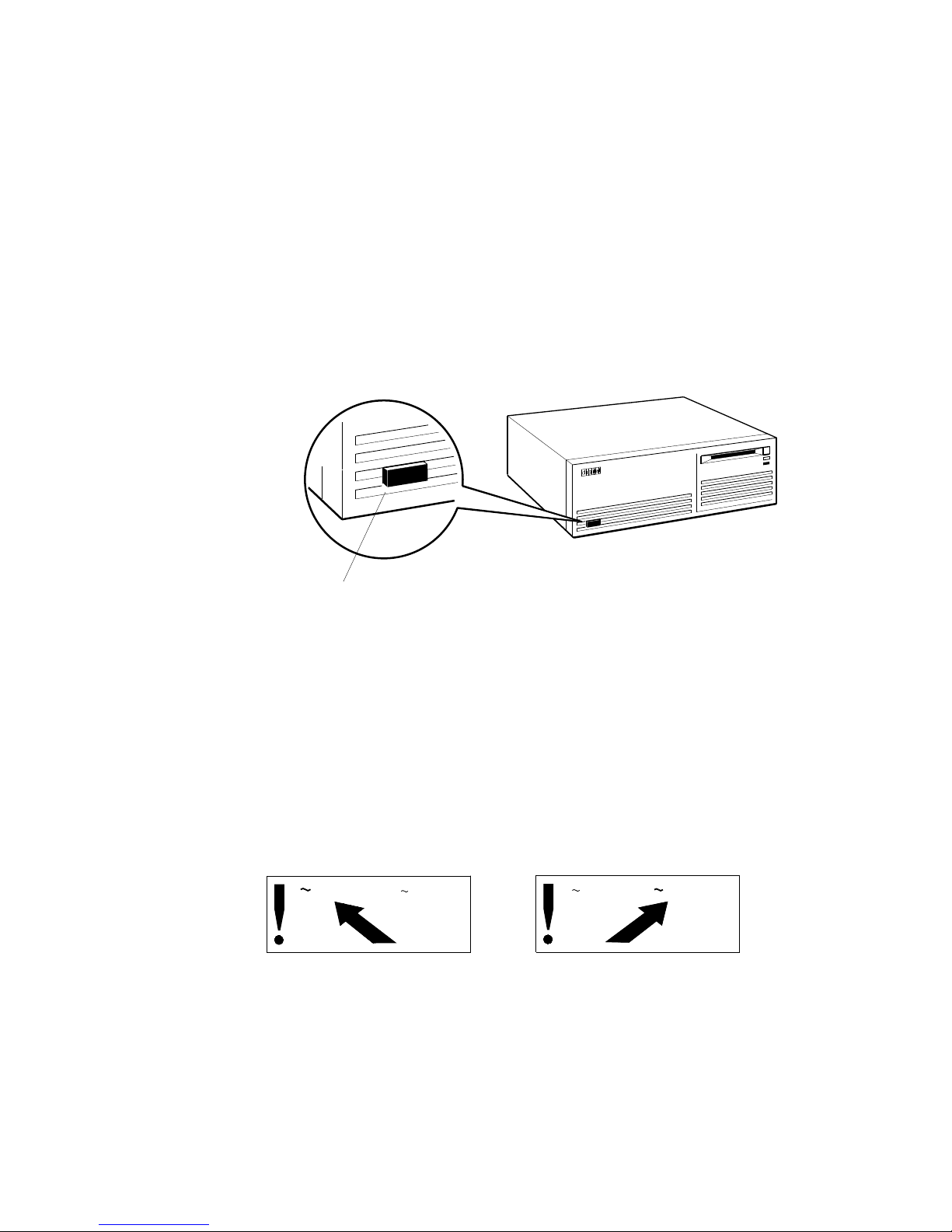
Be sure expansion box on/off switches are in the off
position.
Press the 0 on the on/off switch on the BA42 storage expansion
box, the TK50Z tape drive expansion box, and the RRD40
optical compact disc drive expansion box.
Press and release the on/off switch on the TLZ04 tape drive to
turn it on and off.
On/off switch
Check voltage requirements.
The voltage for many devices, including most monitors, must
match that of your power source. Where necessary, a yellow
voltage label that covers the power connector on your device
tells you the voltage requirements for that device.
Caution: Connecting a device to a power source that does not meet
the voltage requirements of that device can damage the device.
V 100-120
V 220-240
36-17905-19
TLZ04 tape drive
V 100-120
WSE2I094
V 220-240
36-17905-19
WSE2I021
4
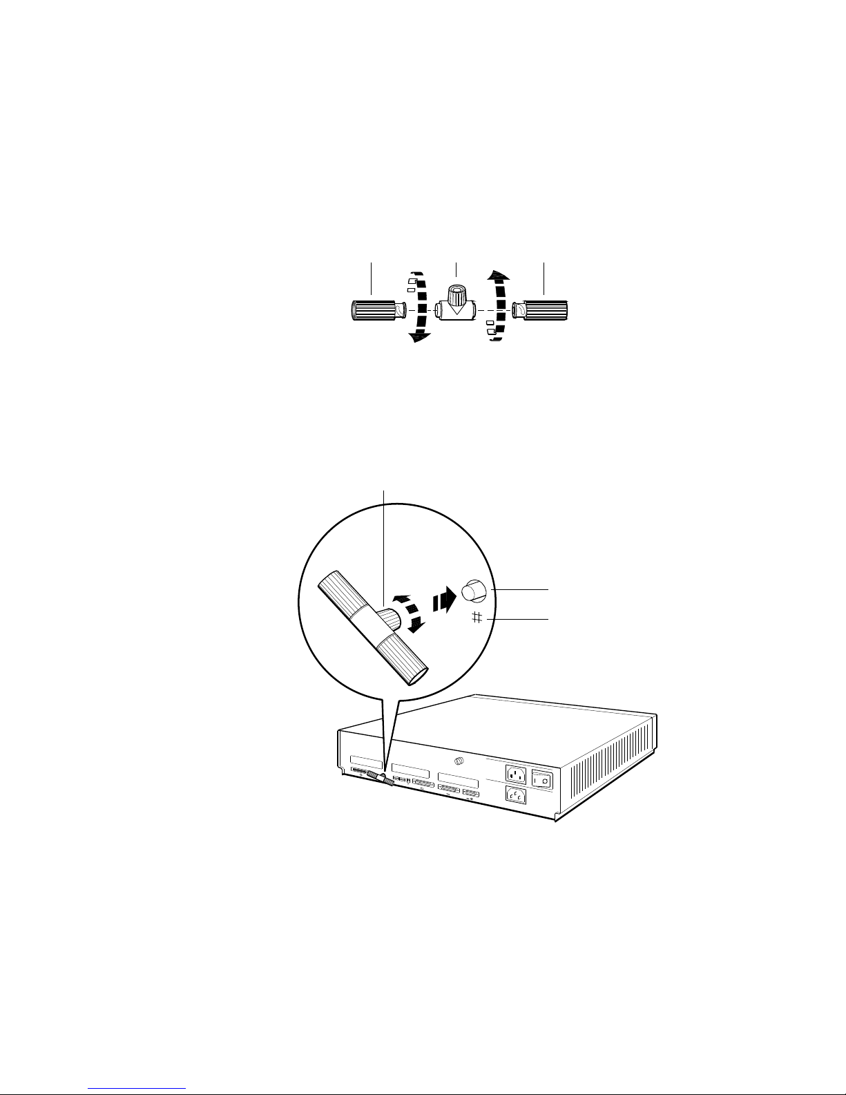
Terminate ThinWire Ethernet.
First terminate the ThinWire T-connector.
Terminator
T-connector
Terminator
WSE2I089
Then connect the T-connector to the ThinWire connector in base
slot 6 on the system unit.
Twist the ribbed portion of the T-connector from side to
side until you can push it into the system unit connector.
Then turn it to the right until it locks into place.
System unit
ThinWire connector
Ethernet icon
0
1
3
V~100-120 A 3.0
V~220-240 A 1.7
2
V~100-120/220-240
A 7.9/4.2
Hz 50-60
W 359
2
WSE2I071
5
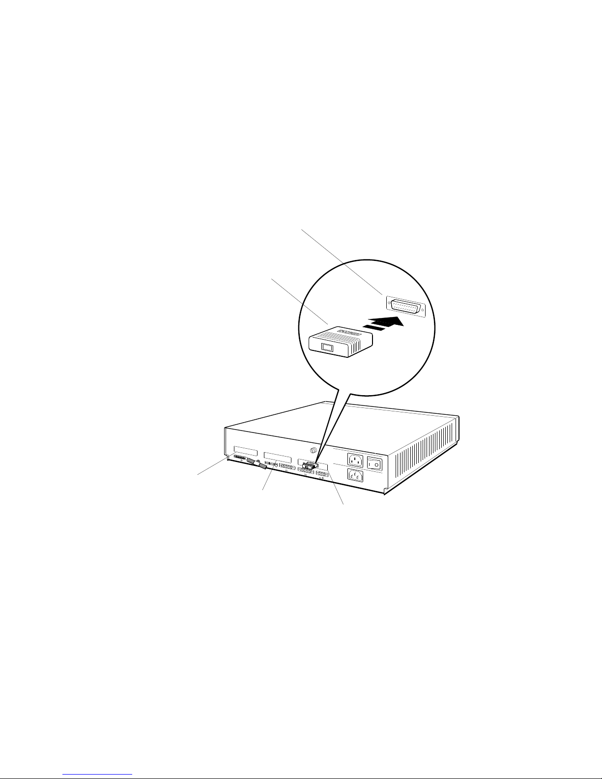
Attach any ThickWire loopback connectors.
Optional ThickWire Ethernet connectors can be present in any
of the option slots on the back of the system unit. Each must
have a loopback connector in place until the Ethernet cable is
connected to the system unit and the network.
System unit
ThickWire connector
Position the loopback
connector so the
Digital logo is on top.
0
1
PMAD-A
3
V~100-120 A 3.0
V~220-240 A 1.7
2
V~100-120/220-240
A 7.9/4.2
Hz 50-60
W 359
2
Option slot 0
Option slot 1
Option slot 2
WSE2I073
6
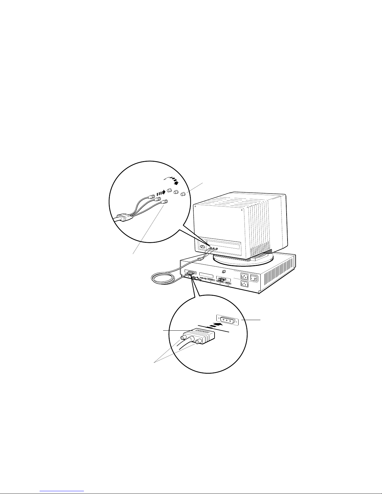
Connect the monitor to the system unit.
To connect a gray-scale monitor, turn to page 8.
To connect a color monitor
Connect the RGB signal cables on the video cable assembly
to the monitor. Then connect the 3-pin connector to the video
connector on the system unit.
Monitor video connectors (If you have a
19-inch VRT19 color monitor, connect the
signal cables to the bottom set of RGB
connectors on the back of the monitor.)
R
G
B
0
0
1
2
PMAD-A
3
2
Turn the signal cable
connectors to your
right until they
slide forward and
lock into place.
R
G
R
G
B
B
PMAG-C
V~100-120 A 3.0
V~220-240 A 1.7
V~100-120/220-240
A 7.9/4.2
Hz 50-60
W 359
Position the 3-pin cable
connector so the Digital
logo is on top.
Turn the screws
to your right to hold
the connector in place.
System unit
video connector
WSE2I069
7
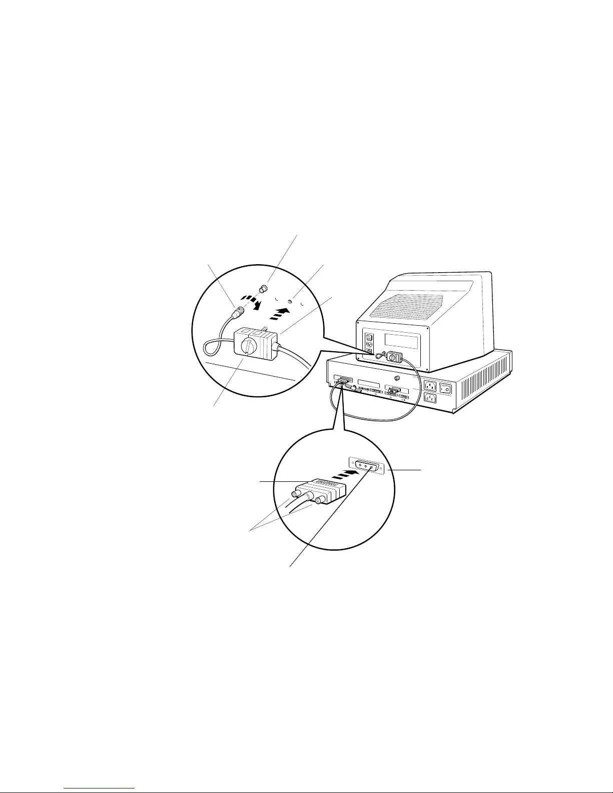
To connect a gray-scale monitor
First attach the round signal cable connector on the video cable
assembly to the monitor and the 3-pin connector to the video
connector on the system unit. Then attach the connector block
to the back of the monitor.
Turn the signal cable
connector to your
right until it slides
forward and locks
into place.
Turn the large plastic
screw to your right to
hold the connector block
in place against the monitor.
Position the 3-pin cable
connector so the Digital
logo is on top.
Monitor video
connector
Attach the connector
block here.
Connector
block
PMAG-C
010
3
V~100-120
V~220-240
2
PMAD-A
V~100-120/
A 7.9/4.2
Hz 50-60
W 359
2
System unit
video connector
Turn the screws
to your right to hold
the connector in place.
8
WSE2I086
 Loading...