

deconta D Series, D 305, D 60 E, D 610, D 910 Instruction Manual
...
Instruction manual
Negative Pressure Unit
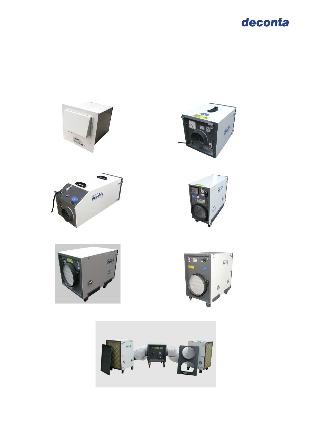
D-Range
D 60 E
D 100
D 610
D 60
D 305
D 910
D 1200

Negative Pressure Unit D-range
Instruction manual
Table of contents
on page
1 Basic safety advices 3
2 Transport and storage 4
2.1 Delivery 4
2.2 Transport 4
2.3 Storage 4
3 Volume of delivery at purchase and rent 5
3.1 Volume of delivery 5
3.2 Return of delivery after ending of the rental time 5
4 Technical description 6
4.1 Intended use 6
4.2 Unit description 6
4.3 Control ON / OFF 7
4.4 Control SE 8
4.5 Control SRE 8
4.6 Filter description/ classification 9
4.7 Instructions regarding filter change 11
4.8 Stacking of several units 12
5 Technical data 13
5.1 Fan characteristic curve D 60 E and D60 13
5.2 Fan characteristic curve D 100 14
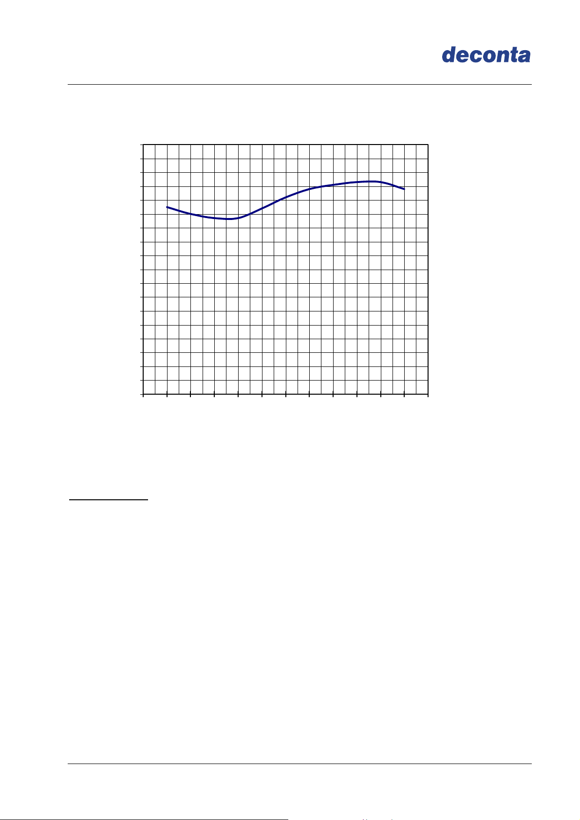
5.3 Fan characteristic curve D 305 15
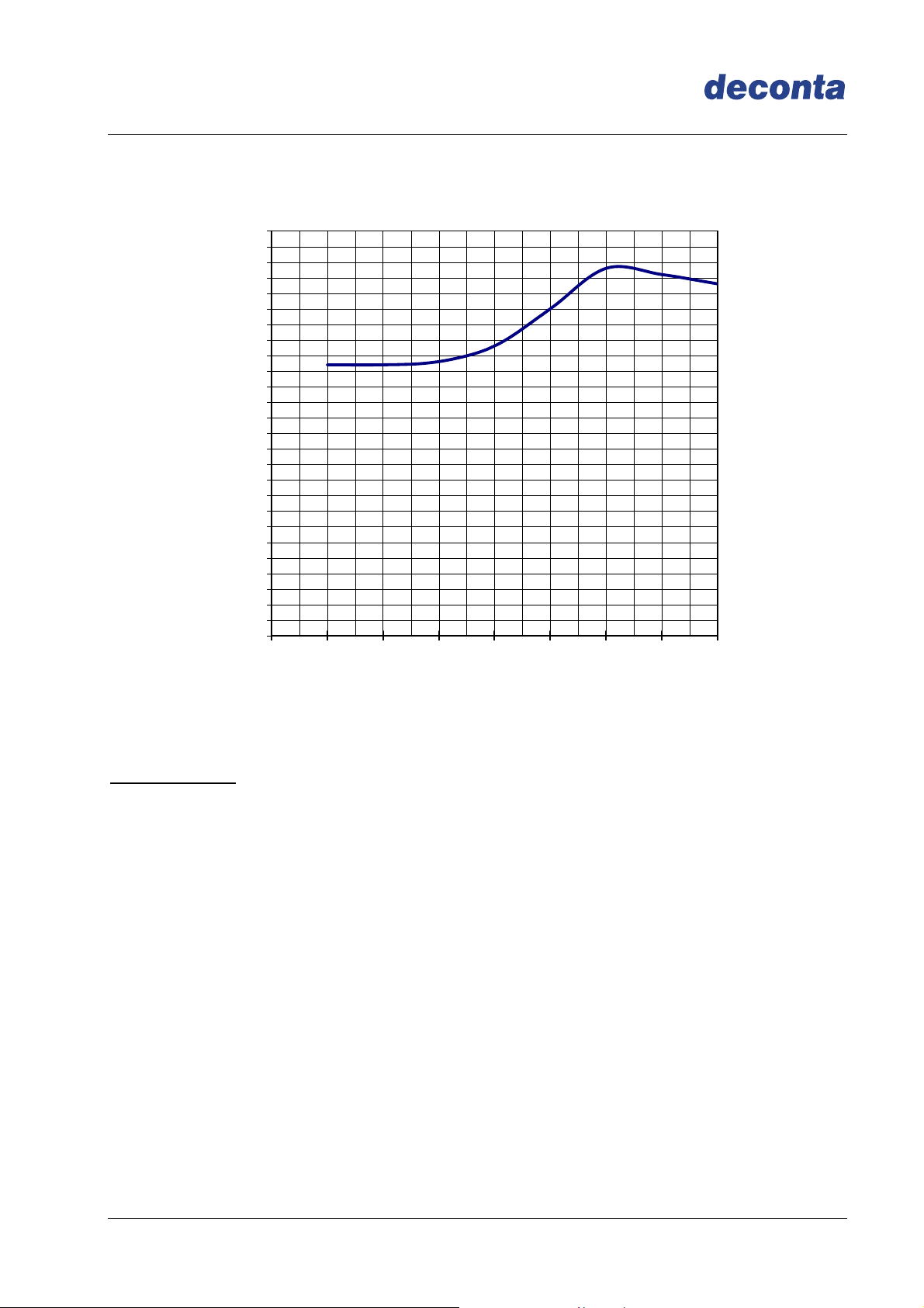
5.4 Fan characteristic curve D 610 16
5.5 Fan characteristic curve D 910 17
5.6 Fan characteristic curve D 1200 18
5.7 Performance data 19
5.8 Connections, dimensions, weights 19
5.9 Power loss in hose lines 20
5.10 Resistor-diagram for hose lines 20
6 Assembly instructions 21
6.1 Assembly instructions with the example of D 610 21
6.2 Assembly instructions with the example of D 1200 22
6.3 Assembly of the optional annex housing (SNA+P) with the example of D 610 24
7 Initial operation 25
7.1 Control ON / OFF 25
7.2 Control SE 25
7.3 Control SRE 26
8 Maintenance 28
8.1 Maintenance 28
8.2 Filter conrtol 28
8.3 Filter change 29
9 Possible failures and their repairs 30
10 Circuit diagrams 31
10.1 Circuit diagram D 60 E 31
10.2 Circuit diagram D 60 SE 32
10.3 Circuit diagram D 100 EIN / AUS 33
10.4 Circuit diagram D 100 SE 34
10.5 Circuit diagram D 100 SRE 35
10.6 Circuit diagram D 305 EIN / AUS 36
10.7 Circuit diagram D 305 SE 37
10.8 Circuit diagram D305 SRE 38
10.9 Circuit diagram D 610 EIN / AUS 39
10.10 Circuit diagram D 610 SE 40
10.11 Circuit diagram D 610 SRE 41
10.12 Circuit diagram D 910 SE 42
10.13 Circuit diagram D 910 SRE 43
10.14 Circuit diagram D 1200 SE 44
10.15 Circuit diagram D 1200 SRE 45
11 Sound level measuring 46
12 Declaration of conformity 47
Page 2

Negative Pressure Unit D-range
Instruction manual
2 Basic safety advices
The handling of the appliance technology is only allowed for instructed staff. The exact
knowledge of the guide book is an important condition for your staff in regard to the
handling of the machine.
deconta has to engage you as the user to follow the guide book and to employ this
engineered technology only in accordance with the regulations and not in a inappropriate
way! In the event of non-observance, deconta assumes no liability.
In order to ensure the safety during the operation of the device, please respect, without
fail, the following:
Do not place in an explosive area
Necessary repairs, maintenance and cleaning, in particular in the field of electrical
equipment may only be realized by qualified staff
For all repairs the device has to be fully disconnected
The safety and security equipments have to be treated with care, ready for use.
the indicated safety advices have to be kept in a readable state and have to be
observed
The standard, legal and remaining binding rules concerning the accident
prevention and the protection of the environment have to be observed
In order to ensure safety, any changes to the machine are prohibited.
ATTENTION!
The device is not suitable for the use in a condensed, corrosive, flammable and
explosive compartment air.
We refer specifically to additional regional and national security measures and
rules by the operation of the engineered equipment.
The control of the exhaust has to be effected during the initial operation as well as at
least in 3 years interval.
Page 3

Negative Pressure Unit D-range
Instruction manual
2 Transport and storage
2.1 Delivery
The negative pressure unit is delivered from deconta works Isselburg on a pallet. In
order to protect the device against climatic influences it is wrapped with a plastic film.
Transport damages have to be documented at once during the handing over of the
carrier or another supplier. Please note the possible damages additionally on the way bill.
2.2 Transport
Transport the device only in a decontaminated state.
The device can be transported by one person.
For the easy handling, the device has got carry handles.
A specially tuned gear for the machines enables the moving on even surface (D 305, D
610, D 910, D 1200).
In order to lift the devices, there are handles on the device.
2.3 Storage
Store the device only in a decontaminated state.
In order to avoid damages, the installation has to be kept in a dried area with no access
for unauthorized persons.
Shut the suction and exhaust connections with the transport lids.
Page 4

Negative Pressure Unit D-range
Instruction manual
3 Volume of delivery at sale or rent
3.1 Volume of delivery
The volume of delivery of a negative pressure unit unless no other agreements have
been made, consists of:
Negative pressure unit
Instruction manual
Transport lid
Plastic lid
Complete filter set
Packaging
3.2 Return delivery after the termination of the rent period
For the protection of our clients and in accordance with the rules for hazmat transport,
we must insist on the following return delivery conditions:
Cleaned thoroughly (ready for use)
Completely free of adhesive rests
Complete, as described under 3.1 however without filter set
Without damages
Page 5

Negative Pressure Unit D-range
Instruction manual
4 Technical description
4.1 Use according to appropriateness
The negative pressure unit of the D-Series serves for the filtration of asbestos
contaminated air, in temperature rage up +45 °C, with external exhaust for the air. During
asbestos sanitation works within closed rooms, you must avoid that asbestos fibres leave
the sanitation area and in this way endanger humans and the environment. For this
reasons, the sanitation areas (also called dirty area) have to be separated from the clean
area with the help of a negative pressure unit and kept in dynamic negative pressure.
An integrated filtering system establishes the conditions that the asbestos concentration
in the exhausted air does not exceed max. 1000F/m³. The exhausted air is blown in the
open air.
The device is not appropriate for the filtration of flammable gas or dust.
4.2 Description of the device
The negative pressure unit serves for the filtration of asbestos contaminated air via a 3steps filter unit. (D 60 and D 60 E only 2-steps). The inserted Hepa filter complies with
the requirements according to EN 1822 classification H13.
By stacking of several devices, minor floor space is needed.
Smooth and easy-to-decontaminate housing
Stable and light housing
3-fold sealed hepa filter
Hepa filter according to EN 1822 classification H13
Very low emission during the change of the filter. Filter change in 3 minutes
The filter change is indicated visually via a pressure gauge (for the D 60 E via a
signal lighting)
Rustproof and powder coated housing
continuously variable control 0 - 100% (SE and SRE)
automatic soft starting, also after a power failure
all operation and function elements are shock-protected
stackable housing, ergo minor floor space
Power optimised fan with high capacity
Options:
Attachment housing for the second hepa filter (Double filtration)
Attachment housing for pocket filter
Acoustical indication for the filter change
Suction adapter
Page 6
Negative Pressure Unit D-range
Instruction manual
You can obtain the control of the negative pressure unit optionally in following models:
D 60 E:
ON / OFF
D60
manual, continuously variable control SE
D 100
ON /OFF
manual, continuously variable control SE
automatic control SRE
D 305
ON /OFF
Manual, continuously variable control SE
Automatic control SRE
D 610
ON /OFF
Manual, continuously variable control SE
Automatic control SRE
D 910
Manual, continuously variable control SE
Automatic control SRE
D 1200
ON /OFF (only for 400 V / 32 A)
Manual, continuously variable control SE
Automatic control SRE
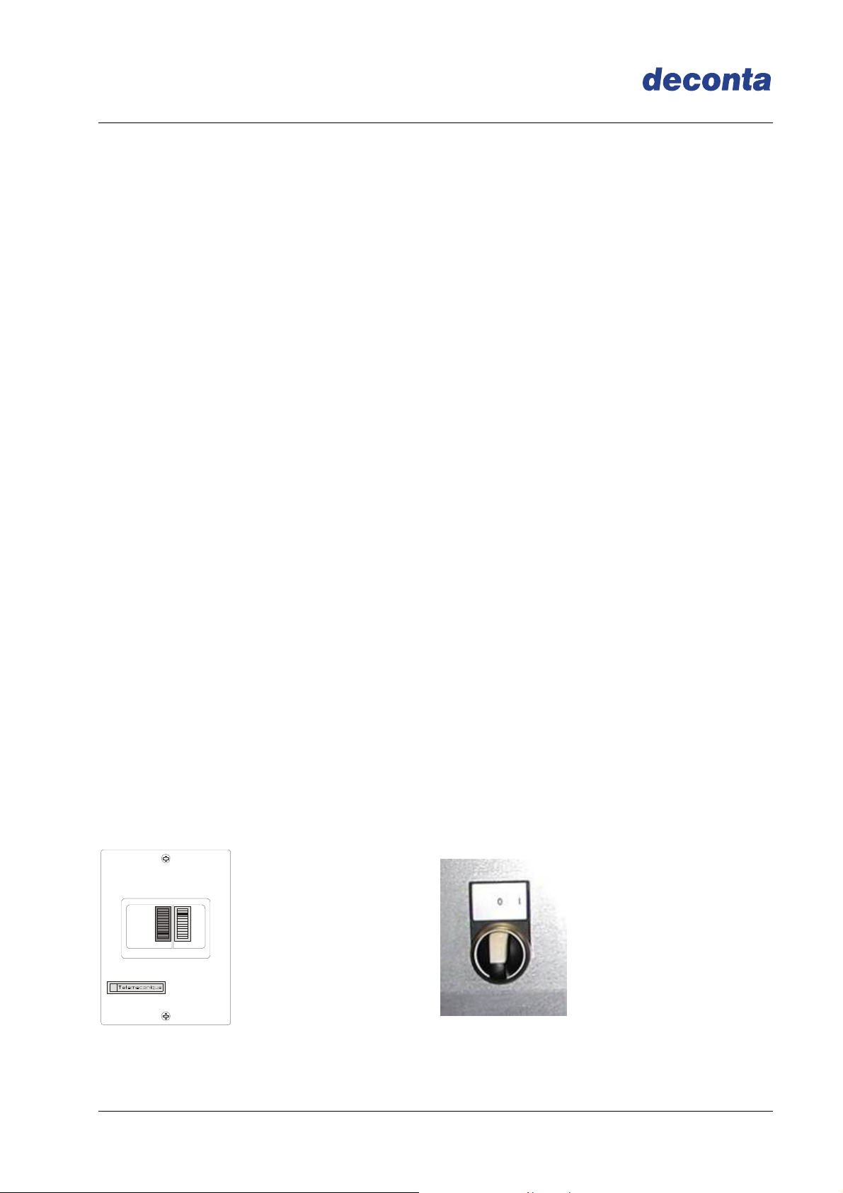
4.3 Control ON / OFF
For the power regulation, the negative pressure unit is delivered in series with an
ON/OFF switch.
D 305
D 610
D 60
D 1200
Page 7
Negative Pressure Unit D-range
Instruction manual
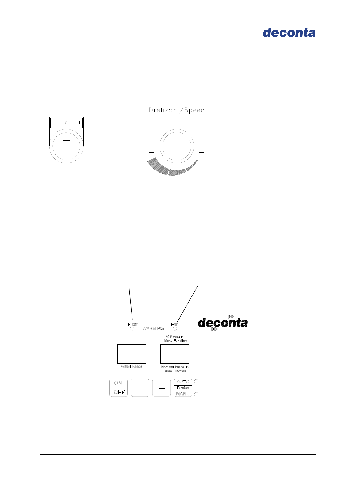
4.4 Control SE
For the power regulation the negative pressure unit is delivered in series with a manual
continuously variable control.
4.5 Control SRE
For the power regulation the negative pressure unit is delivered in series with an
electronic control, in order to measure and to regulate the negative pressure. The
negative pressure is measured between the dirty area and at a reference point to be
determined (adjoining rooms) and the set point is kept by the continuous speed
regulation of the electric fan.
On reaching the maximal fan capacity, a LED Fan will beam.
The necessary filter change will be indicated by the LED Filter
LED „Filter“ LED „Fan“
Page 8
Negative Pressure Unit D-range
Instruction manual
4.6 Description of the filter / classification
Integrated in the unit is a 3-step filtering combination (D 60 and D 60 E only 2-steps).
In particular:
Pre- and intermediate filter Pre-filter Intermediate filter
Filter class according to DIN 24185 / EN
779
Frame
G3 / EU3 G4 / EU4
Cardboard frame,
47 mm width
Cardboard frame,
47 mm width
Filter medium Fiber glass Synthetic
Degree of separation (Am) 85 % 90 %
Nominal rated current: 5400m³/h/m² 5400m³/h/m²
Nominal velocity in blower stream at
nominal volume
1,5 m/s 1,5 m/s
Difference of initial pressure 30 Pa 42 Pa
Recommended difference of final pressure 450 Pa 250 Pa
Temperature / Air humidity
Filter dimensions (in mm):
D 60 E
D 60
D 100
D 305
D 610
D 910
D 1200
100°C/100% RF
(relative humidity)
-
305 x 305 x 47
305 x 610 x 47
610 x 610 x 47
610 x 910 x 47
610 x 910 x 47
100°C/100% RF
(relative humidity)
305 x 305 x 47
305 x 305 x 47
305 x 305 x 47
305 x 610 x 47
610 x 610 x 47
610 x 910 x 47
610 x 910 x 47
Page 9
Negative Pressure Unit D-range
Instruction manual
Hepa filter, suspended matter filter (S)
Frame Plastic
Filter medium Micro fiber glass paper
Sealing mass Polyurethane
Seals Polyurethane
Filter surface
D 60 E
D 60
D 100
D 305
D 610
D 910
D 1200
2 m²
2 m²
7 m²
15 m²
31 m²
48 m²
48 m²
Filter classification H13 according to EN 1822
Degree of separation >99,95%Most Penetraded Partikel Size
Temperature / Air humidity
Filter dimensions (in mm):
D 60 E
D 60
D 100
D 305
D 610
D 910
D 1200
70°C/100% RF
(relative humidity)
284 x 284 x 150
284 x 284 x 150
305 x 305 x 292
305 x 610 x 292
610 x 610 x 292
610 x 910 x 292
610 x 910 x 292
Protective grid Grid, both sides
Page 10
Negative Pressure Unit D-range
Instruction manual
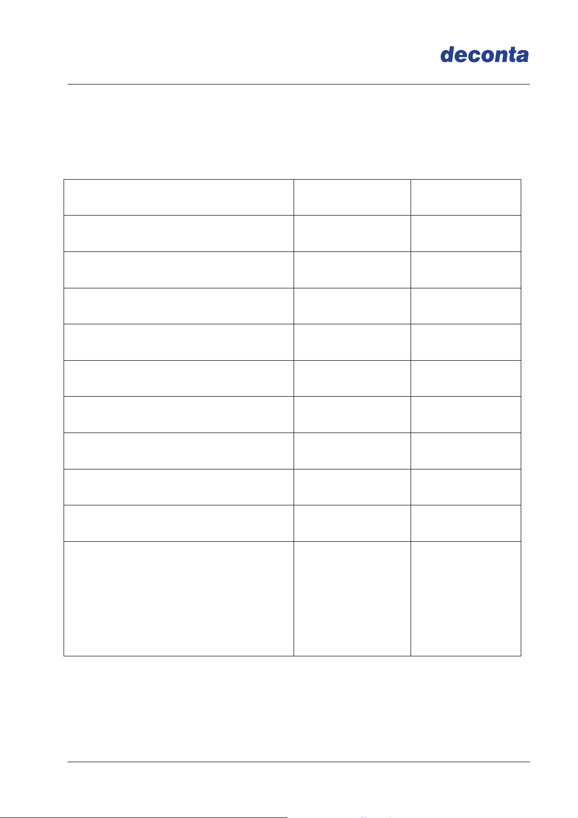
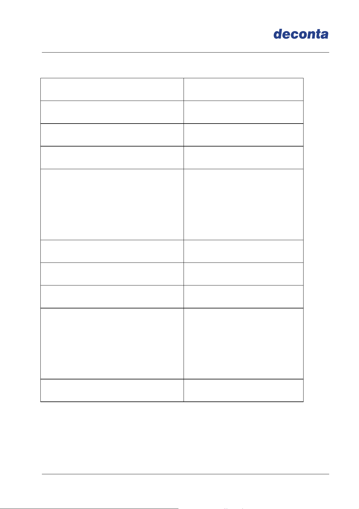
4.7 Information regarding the change of filter
The frequency of the change of filter depends on the degree of pollution of the filter. If the
sealing up of the filter increases (contamination of the filter), the air capacity decreases.
For the control of the filter during the operation, the device is equipped with a manometer
(for D 60 E a signal light).
Important: Use only approved, faultless filter!
From the following chart you can take for the change of the filter, the indications of
values for the filter as-new condition and the indications of the recommended change of
the filter. If the indication reaches the value for the recommended change of filter do
please first change the preliminary and intermediate filter. If the indication falls at 100
Pascal (for D 60 at 50 Pascal) or more, the device can be operated further. If the value
falls at lesser than 100 Pascal (for D 60 at 50 Pascal), you have to change the Hepa filter
Device As-new condition
Recommended filter
change by
D 60 350 Pascal 470 Pascal
D 100 500 Pascal 750 Pascal
D 305 650 Pascal 950 Pascal
D 610 650 Pascal 1000 Pascal
D 910 700 Pascal 1100 Pascal
D 1200 650 Pascal 900 Pascal
Page 11
Negative Pressure Unit D-range
Instruction manual
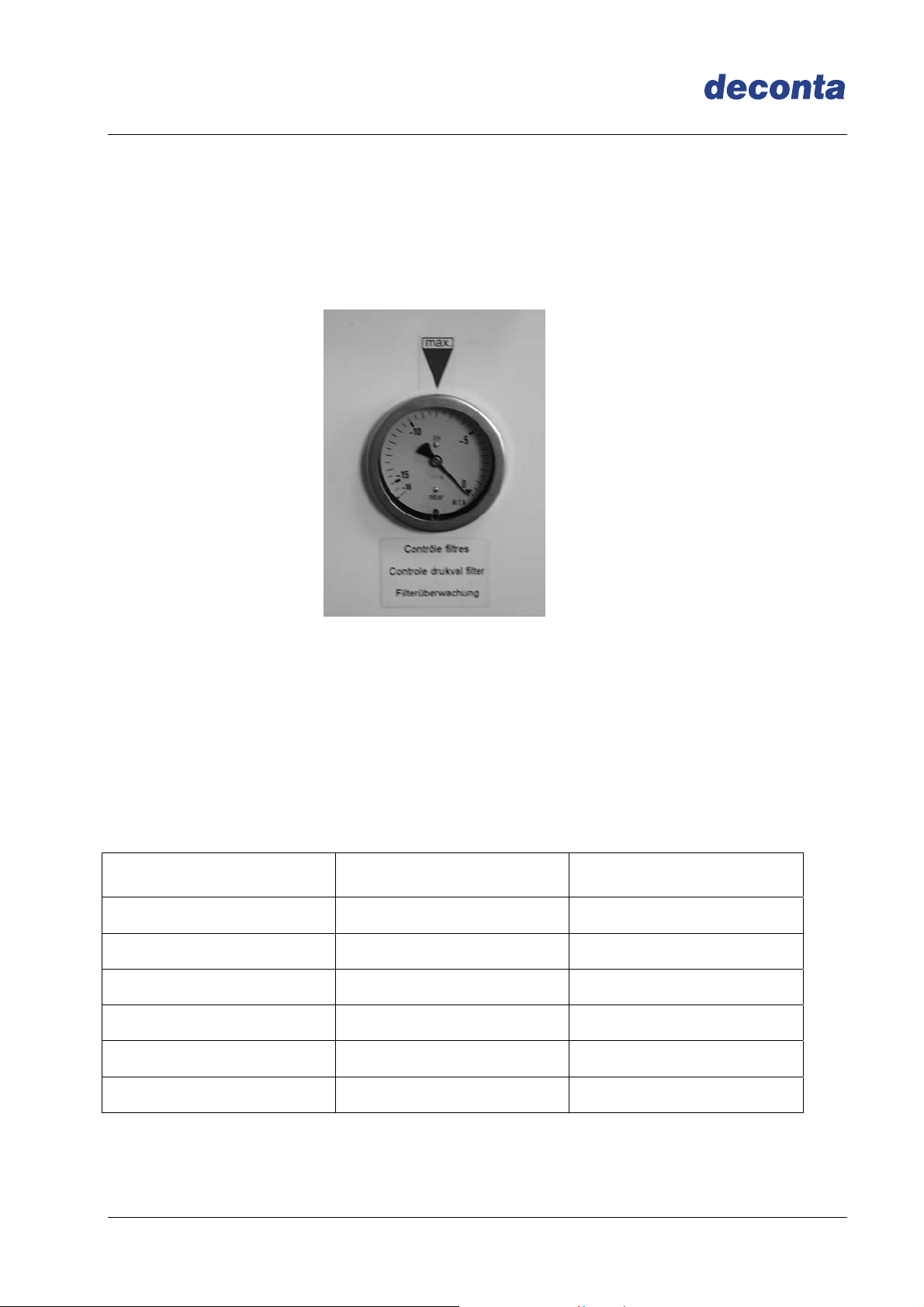
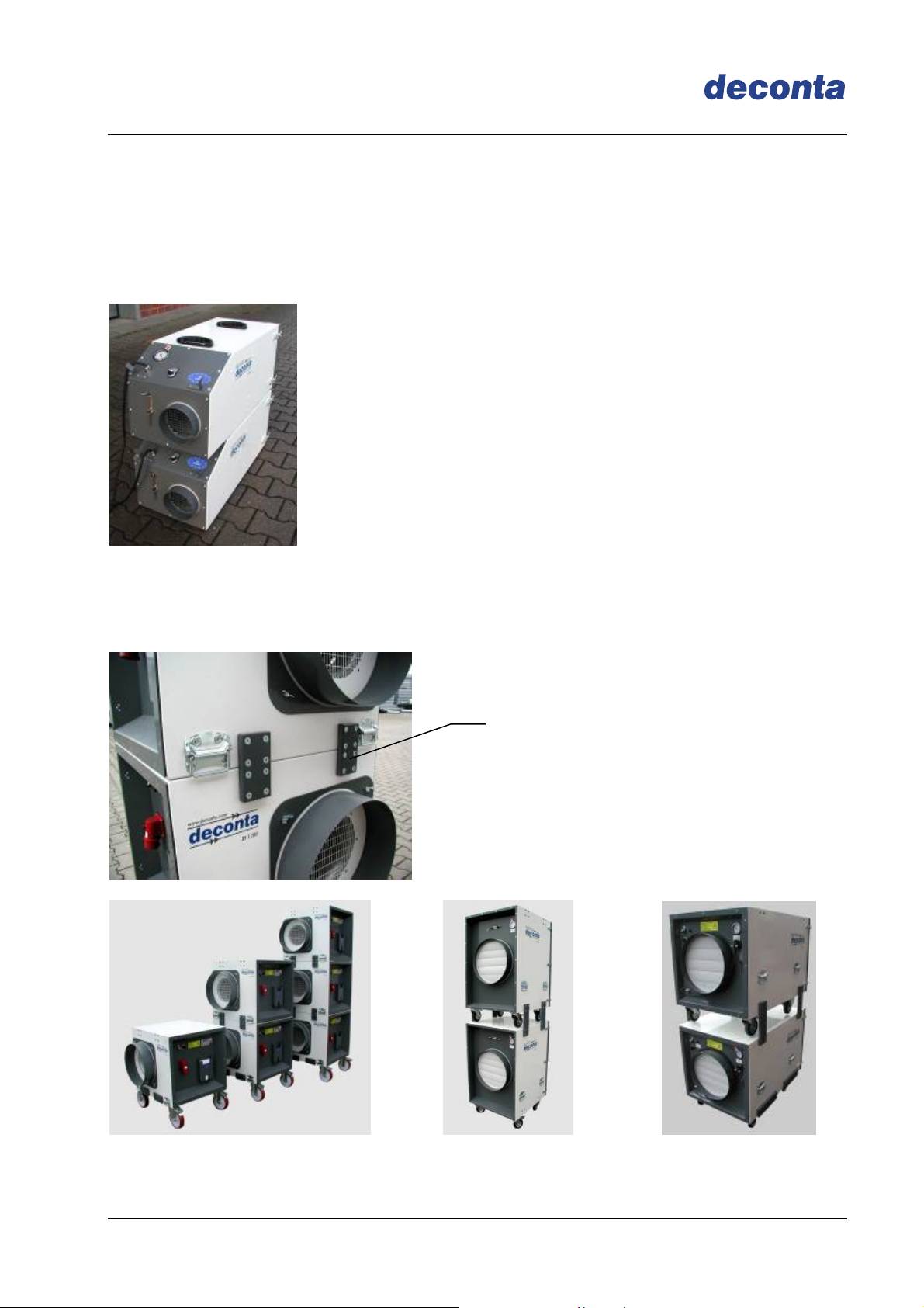
4.8 Piling of several devices
The negative pressure units of the D-range can be pilled (except D 60 E) in order to
obtain a floor space as small as possible.
D 60 and D 100 are pilled thanks to an anti-skidding centering facility.
D 305, D 610, D910 and D 1200 are connected thanks to a tight and solid screwed pilling
system
Pilling system
Page 12
V
Negative Pressure Unit D-range
Instruction manual
5 Technical data
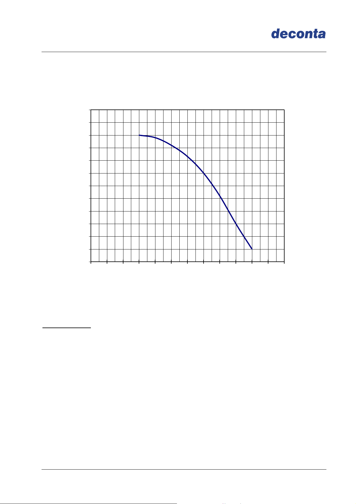
5.1 Fan characteristic curve D 60 E and D 60
600
550
500
450
400
350
300
250
200
150
100
stat. Pressure boosting PA =>
50
0
0 100 200 300 400 500 600 700 800 900 1000 1100 1200
olume flow V m³/h =>
Technical data:
Voltage: 230 V
Frequency: 50 Hz
Speed: 2890 U/min
Air discharge: 980 m³/h free exhausting
max. discharge temperature: 45°C
Page 13
V
Negative Pressure Unit D-range
Instruction manual
5.2 Fan charasteristic curve D 100
900
850
800
750
700
650
600
550
500
450
400
350
300
250
200
stat. Pressure boosting PA =>
150
100
50
0
0 130 200 300 400 500 600 700 800 900 1000 1100
olume flow V m³/h =>
Technical data:
Voltage: 230 V
Frequency: 50 Hz
Speed: 2850 U/min
Air discharge: 1200 m³/h free exhausting
max. discharge temperature: 45°C
Page 14
V
Negative Pressure Unit D-range
Instruction manual
5.3 Fan characteristic curve D 305
1300
1250
1200
1150
1100
1050
1000
950
900
850
800
750
700
650
600
550
500
450
400
350
stat. Pressure boosting PA =>
300
250
200
150
100
50
0
0 350 400 500 700 1000 1500 2000 2200
olume flow V m³/h =>
Technical data:
Voltage: 230 V
Frequency: 50 Hz
Speed: 2850 U/min
Air discharge: 2400 m³/h free exhaust
max. discharge temperature: 45°C
Page 15
 Loading...