

Instruction manual
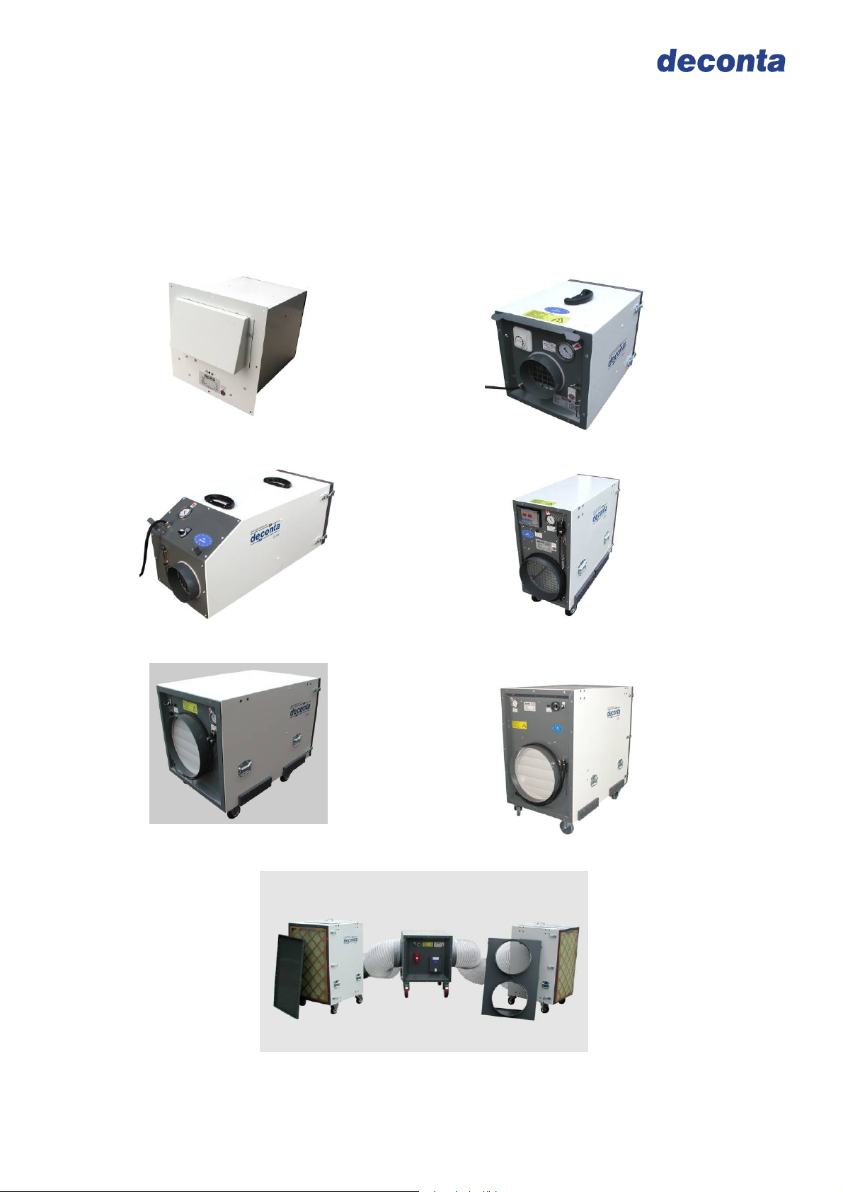
Negative Pressure Unit
D-Range
D 60 E
D 100
D 610
D 60
D 305
D 910
D 1200

Negative Pressure Unit D-range
Instruction manual
Table of contents
on page
1 Basic safety advices 3
2 Transport and storage 4
2.1 Delivery 4
2.2 Transport 4
2.3 Storage 4
3 Volume of delivery at purchase and rent 5
3.1 Volume of delivery 5
3.2 Return of delivery after ending of the rental time 5
4 Technical description 6
4.1 Intended use 6
4.2 Unit description 6
4.3 Control ON / OFF 7
4.4 Control SE 8
4.5 Control SRE 8
4.6 Filter description/ classification 9
4.7 Instructions regarding filter change 11
4.8 Stacking of several units 12
5 Technical data 13
5.1 Fan characteristic curve D 60 E and D60 13
5.2 Fan characteristic curve D 100 14
5.3 Fan characteristic curve D 305 15
5.4 Fan characteristic curve D 610 16
5.5 Fan characteristic curve D 910 17
5.6 Fan characteristic curve D 1200 18
5.7 Performance data 19
5.8 Connections, dimensions, weights 19
5.9 Power loss in hose lines 20
5.10 Resistor-diagram for hose lines 20
6 Assembly instructions 21
6.1 Assembly instructions with the example of D 610 21
6.2 Assembly instructions with the example of D 1200 22
6.3 Assembly of the optional annex housing (SNA+P) with the example of D 610 24
7 Initial operation 25
7.1 Control ON / OFF 25
7.2 Control SE 25
7.3 Control SRE 26
8 Maintenance 28
8.1 Maintenance 28
8.2 Filter conrtol 28
8.3 Filter change 29
9 Possible failures and their repairs 30
10 Circuit diagrams 31
10.1 Circuit diagram D 60 E 31
10.2 Circuit diagram D 60 SE 32
10.3 Circuit diagram D 100 EIN / AUS 33
10.4 Circuit diagram D 100 SE 34
10.5 Circuit diagram D 100 SRE 35
10.6 Circuit diagram D 305 EIN / AUS 36
10.7 Circuit diagram D 305 SE 37
10.8 Circuit diagram D305 SRE 38
10.9 Circuit diagram D 610 EIN / AUS 39
10.10 Circuit diagram D 610 SE 40
10.11 Circuit diagram D 610 SRE 41
10.12 Circuit diagram D 910 SE 42
10.13 Circuit diagram D 910 SRE 43
10.14 Circuit diagram D 1200 SE 44
10.15 Circuit diagram D 1200 SRE 45
11 Sound level measuring 46
12 Declaration of conformity 47
Page 2

Negative Pressure Unit D-range
Instruction manual
2 Basic safety advices
The handling of the appliance technology is only allowed for instructed staff. The exact
knowledge of the guide book is an important condition for your staff in regard to the
handling of the machine.
deconta has to engage you as the user to follow the guide book and to employ this
engineered technology only in accordance with the regulations and not in a inappropriate
way! In the event of non-observance, deconta assumes no liability.
In order to ensure the safety during the operation of the device, please respect, without
fail, the following:
Do not place in an explosive area
Necessary repairs, maintenance and cleaning, in particular in the field of electrical
equipment may only be realized by qualified staff
For all repairs the device has to be fully disconnected
The safety and security equipments have to be treated with care, ready for use.
the indicated safety advices have to be kept in a readable state and have to be
observed
The standard, legal and remaining binding rules concerning the accident
prevention and the protection of the environment have to be observed
In order to ensure safety, any changes to the machine are prohibited.
ATTENTION!
The device is not suitable for the use in a condensed, corrosive, flammable and
explosive compartment air.
We refer specifically to additional regional and national security measures and
rules by the operation of the engineered equipment.
The control of the exhaust has to be effected during the initial operation as well as at
least in 3 years interval.
Page 3

Negative Pressure Unit D-range
Instruction manual
2 Transport and storage
2.1 Delivery
The negative pressure unit is delivered from deconta works Isselburg on a pallet. In
order to protect the device against climatic influences it is wrapped with a plastic film.
Transport damages have to be documented at once during the handing over of the
carrier or another supplier. Please note the possible damages additionally on the way bill.
2.2 Transport
Transport the device only in a decontaminated state.
The device can be transported by one person.
For the easy handling, the device has got carry handles.
A specially tuned gear for the machines enables the moving on even surface (D 305, D
610, D 910, D 1200).
In order to lift the devices, there are handles on the device.
2.3 Storage
Store the device only in a decontaminated state.
In order to avoid damages, the installation has to be kept in a dried area with no access
for unauthorized persons.
Shut the suction and exhaust connections with the transport lids.
Page 4
Negative Pressure Unit D-range
Instruction manual
3 Volume of delivery at sale or rent
3.1 Volume of delivery
The volume of delivery of a negative pressure unit unless no other agreements have
been made, consists of:
Negative pressure unit
Instruction manual
Transport lid
Plastic lid
Complete filter set
Packaging
3.2 Return delivery after the termination of the rent period
For the protection of our clients and in accordance with the rules for hazmat transport,
we must insist on the following return delivery conditions:
Cleaned thoroughly (ready for use)
Completely free of adhesive rests
Complete, as described under 3.1 however without filter set
Without damages
Page 5

Negative Pressure Unit D-range
Instruction manual
4 Technical description
4.1 Use according to appropriateness
The negative pressure unit of the D-Series serves for the filtration of asbestos
contaminated air, in temperature rage up +45 °C, with external exhaust for the air. During
asbestos sanitation works within closed rooms, you must avoid that asbestos fibres leave
the sanitation area and in this way endanger humans and the environment. For this
reasons, the sanitation areas (also called dirty area) have to be separated from the clean
area with the help of a negative pressure unit and kept in dynamic negative pressure.
An integrated filtering system establishes the conditions that the asbestos concentration
in the exhausted air does not exceed max. 1000F/m³. The exhausted air is blown in the
open air.
The device is not appropriate for the filtration of flammable gas or dust.
4.2 Description of the device
The negative pressure unit serves for the filtration of asbestos contaminated air via a 3steps filter unit. (D 60 and D 60 E only 2-steps). The inserted Hepa filter complies with
the requirements according to EN 1822 classification H13.
By stacking of several devices, minor floor space is needed.
Smooth and easy-to-decontaminate housing
Stable and light housing
3-fold sealed hepa filter
Hepa filter according to EN 1822 classification H13
Very low emission during the change of the filter. Filter change in 3 minutes
The filter change is indicated visually via a pressure gauge (for the D 60 E via a
signal lighting)
Rustproof and powder coated housing
continuously variable control 0 - 100% (SE and SRE)
automatic soft starting, also after a power failure
all operation and function elements are shock-protected
stackable housing, ergo minor floor space
Power optimised fan with high capacity
Options:
Attachment housing for the second hepa filter (Double filtration)
Attachment housing for pocket filter
Acoustical indication for the filter change
Suction adapter
Page 6
Negative Pressure Unit D-range
Instruction manual
You can obtain the control of the negative pressure unit optionally in following models:
D 60 E:
ON / OFF
D60
manual, continuously variable control SE
D 100
ON /OFF
manual, continuously variable control SE
automatic control SRE
D 305
ON /OFF
Manual, continuously variable control SE
Automatic control SRE
D 610
ON /OFF
Manual, continuously variable control SE
Automatic control SRE
D 910
Manual, continuously variable control SE
Automatic control SRE
D 1200
ON /OFF (only for 400 V / 32 A)
Manual, continuously variable control SE
Automatic control SRE
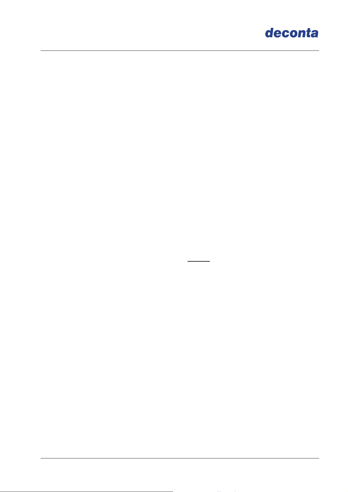
4.3 Control ON / OFF
For the power regulation, the negative pressure unit is delivered in series with an
ON/OFF switch.
D 305
D 610
D 60
D 1200
Page 7
Negative Pressure Unit D-range
Instruction manual
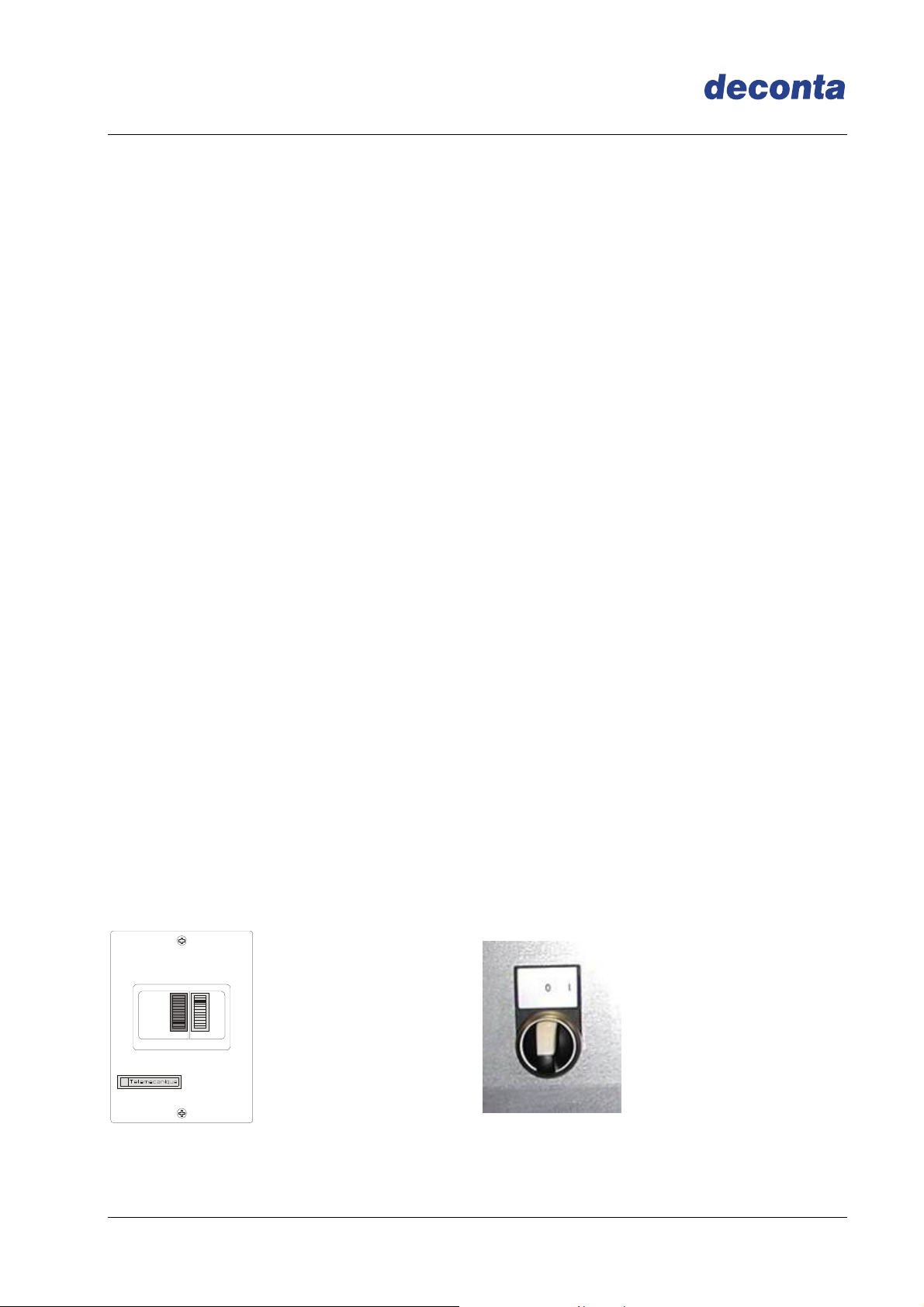
4.4 Control SE
For the power regulation the negative pressure unit is delivered in series with a manual
continuously variable control.
4.5 Control SRE
For the power regulation the negative pressure unit is delivered in series with an
electronic control, in order to measure and to regulate the negative pressure. The
negative pressure is measured between the dirty area and at a reference point to be
determined (adjoining rooms) and the set point is kept by the continuous speed
regulation of the electric fan.
On reaching the maximal fan capacity, a LED Fan will beam.
The necessary filter change will be indicated by the LED Filter
LED „Filter“ LED „Fan“
Page 8
Negative Pressure Unit D-range
Instruction manual
4.6 Description of the filter / classification
Integrated in the unit is a 3-step filtering combination (D 60 and D 60 E only 2-steps).
In particular:
Pre- and intermediate filter Pre-filter Intermediate filter
Filter class according to DIN 24185 / EN
779
Frame
G3 / EU3 G4 / EU4
Cardboard frame,
47 mm width
Cardboard frame,
47 mm width
Filter medium Fiber glass Synthetic
Degree of separation (Am) 85 % 90 %
Nominal rated current: 5400m³/h/m² 5400m³/h/m²
Nominal velocity in blower stream at
nominal volume
1,5 m/s 1,5 m/s
Difference of initial pressure 30 Pa 42 Pa
Recommended difference of final pressure 450 Pa 250 Pa
Temperature / Air humidity
Filter dimensions (in mm):
D 60 E
D 60
D 100
D 305
D 610
D 910
D 1200
100°C/100% RF
(relative humidity)
-
305 x 305 x 47
305 x 610 x 47
610 x 610 x 47
610 x 910 x 47
610 x 910 x 47
100°C/100% RF
(relative humidity)
305 x 305 x 47
305 x 305 x 47
305 x 305 x 47
305 x 610 x 47
610 x 610 x 47
610 x 910 x 47
610 x 910 x 47
Page 9
Negative Pressure Unit D-range
Instruction manual
Hepa filter, suspended matter filter (S)
Frame Plastic
Filter medium Micro fiber glass paper
Sealing mass Polyurethane
Seals Polyurethane
Filter surface
D 60 E
D 60
D 100
D 305
D 610
D 910
D 1200
2 m²
2 m²
7 m²
15 m²
31 m²
48 m²
48 m²
Filter classification H13 according to EN 1822
Degree of separation >99,95%Most Penetraded Partikel Size
Temperature / Air humidity
Filter dimensions (in mm):
D 60 E
D 60
D 100
D 305
D 610
D 910
D 1200
70°C/100% RF
(relative humidity)
284 x 284 x 150
284 x 284 x 150
305 x 305 x 292
305 x 610 x 292
610 x 610 x 292
610 x 910 x 292
610 x 910 x 292
Protective grid Grid, both sides
Page 10
Negative Pressure Unit D-range
Instruction manual
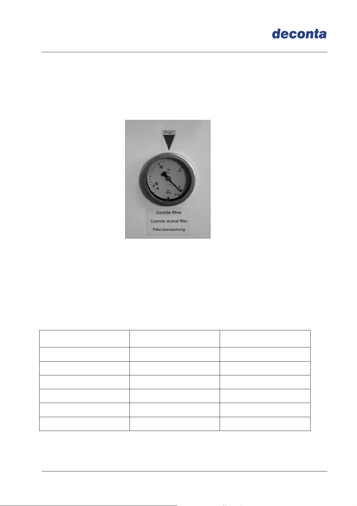
4.7 Information regarding the change of filter
The frequency of the change of filter depends on the degree of pollution of the filter. If the
sealing up of the filter increases (contamination of the filter), the air capacity decreases.
For the control of the filter during the operation, the device is equipped with a manometer
(for D 60 E a signal light).
Important: Use only approved, faultless filter!
From the following chart you can take for the change of the filter, the indications of
values for the filter as-new condition and the indications of the recommended change of
the filter. If the indication reaches the value for the recommended change of filter do
please first change the preliminary and intermediate filter. If the indication falls at 100
Pascal (for D 60 at 50 Pascal) or more, the device can be operated further. If the value
falls at lesser than 100 Pascal (for D 60 at 50 Pascal), you have to change the Hepa filter
Device As-new condition
Recommended filter
change by
D 60 350 Pascal 470 Pascal
D 100 500 Pascal 750 Pascal
D 305 650 Pascal 950 Pascal
D 610 650 Pascal 1000 Pascal
D 910 700 Pascal 1100 Pascal
D 1200 650 Pascal 900 Pascal
Page 11
Negative Pressure Unit D-range
Instruction manual
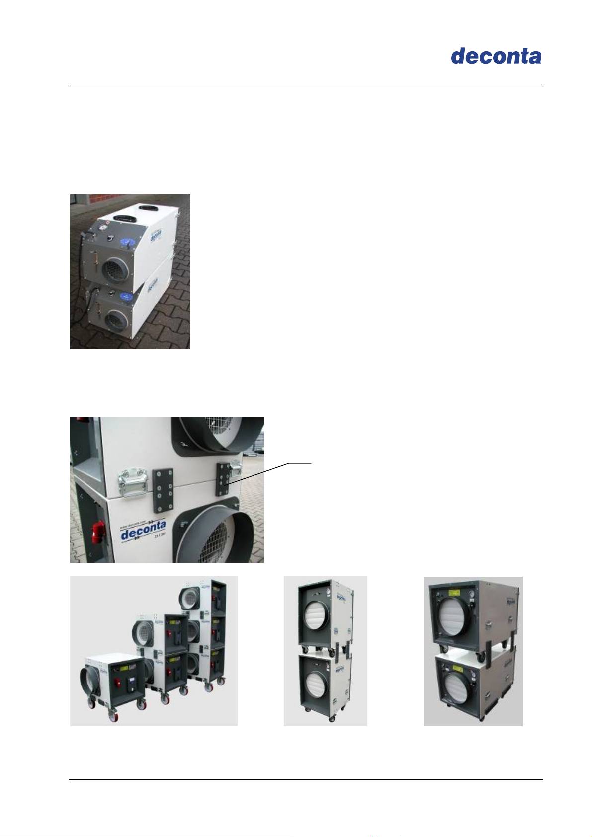
4.8 Piling of several devices
The negative pressure units of the D-range can be pilled (except D 60 E) in order to
obtain a floor space as small as possible.
D 60 and D 100 are pilled thanks to an anti-skidding centering facility.
D 305, D 610, D910 and D 1200 are connected thanks to a tight and solid screwed pilling
system
Pilling system
Page 12
V
Negative Pressure Unit D-range
Instruction manual
5 Technical data
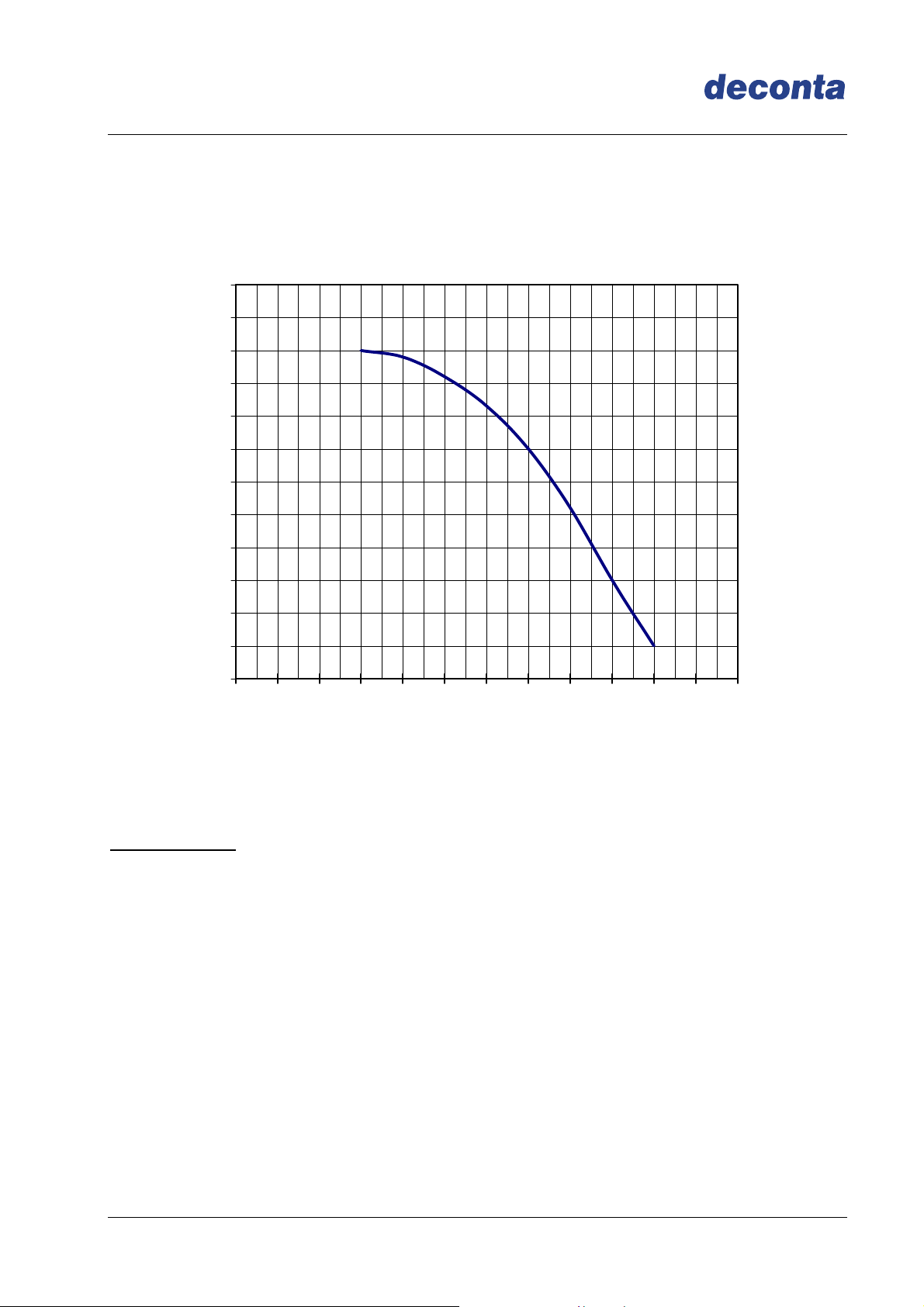
5.1 Fan characteristic curve D 60 E and D 60
600
550
500
450
400
350
300
250
200
150
100
stat. Pressure boosting PA =>
50
0
0 100 200 300 400 500 600 700 800 900 1000 1100 1200
olume flow V m³/h =>
Technical data:
Voltage: 230 V
Frequency: 50 Hz
Speed: 2890 U/min
Air discharge: 980 m³/h free exhausting
max. discharge temperature: 45°C
Page 13
V
Negative Pressure Unit D-range
Instruction manual
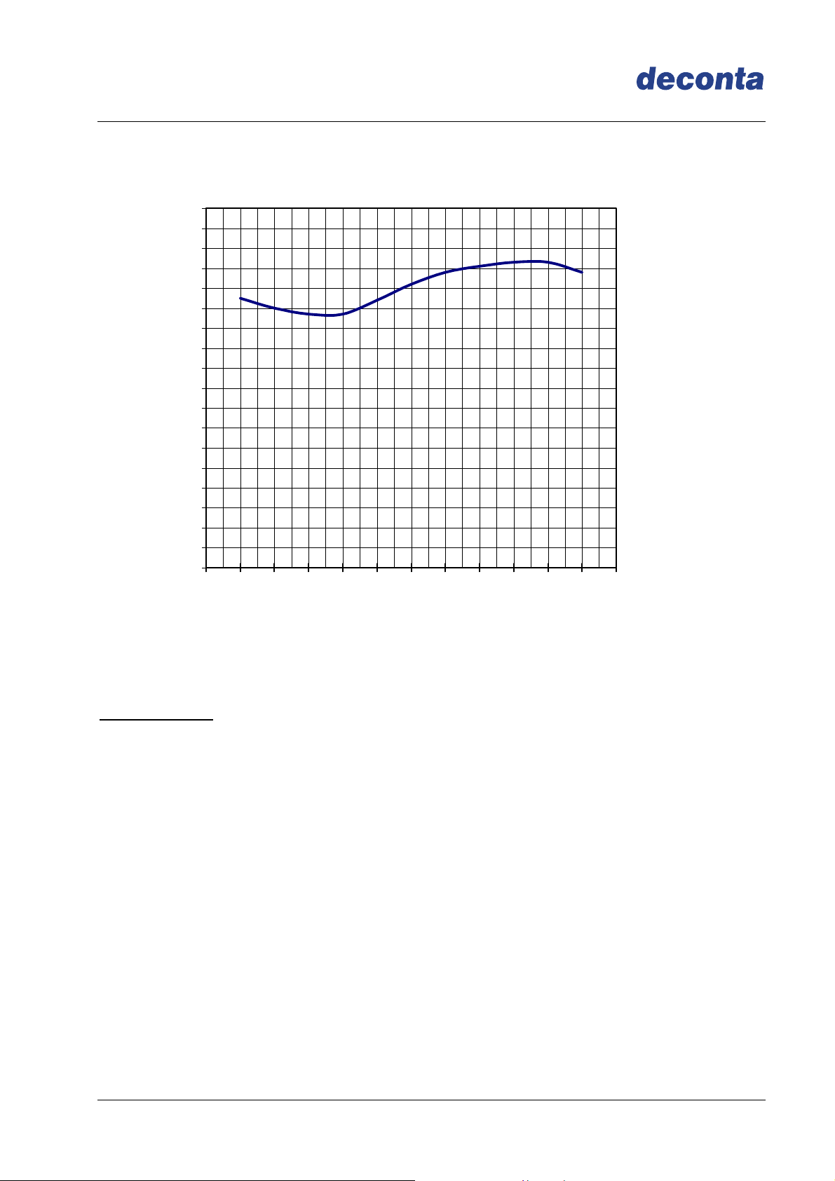
5.2 Fan charasteristic curve D 100
900
850
800
750
700
650
600
550
500
450
400
350
300
250
200
stat. Pressure boosting PA =>
150
100
50
0
0 130 200 300 400 500 600 700 800 900 1000 1100
olume flow V m³/h =>
Technical data:
Voltage: 230 V
Frequency: 50 Hz
Speed: 2850 U/min
Air discharge: 1200 m³/h free exhausting
max. discharge temperature: 45°C
Page 14
V
Negative Pressure Unit D-range
Instruction manual
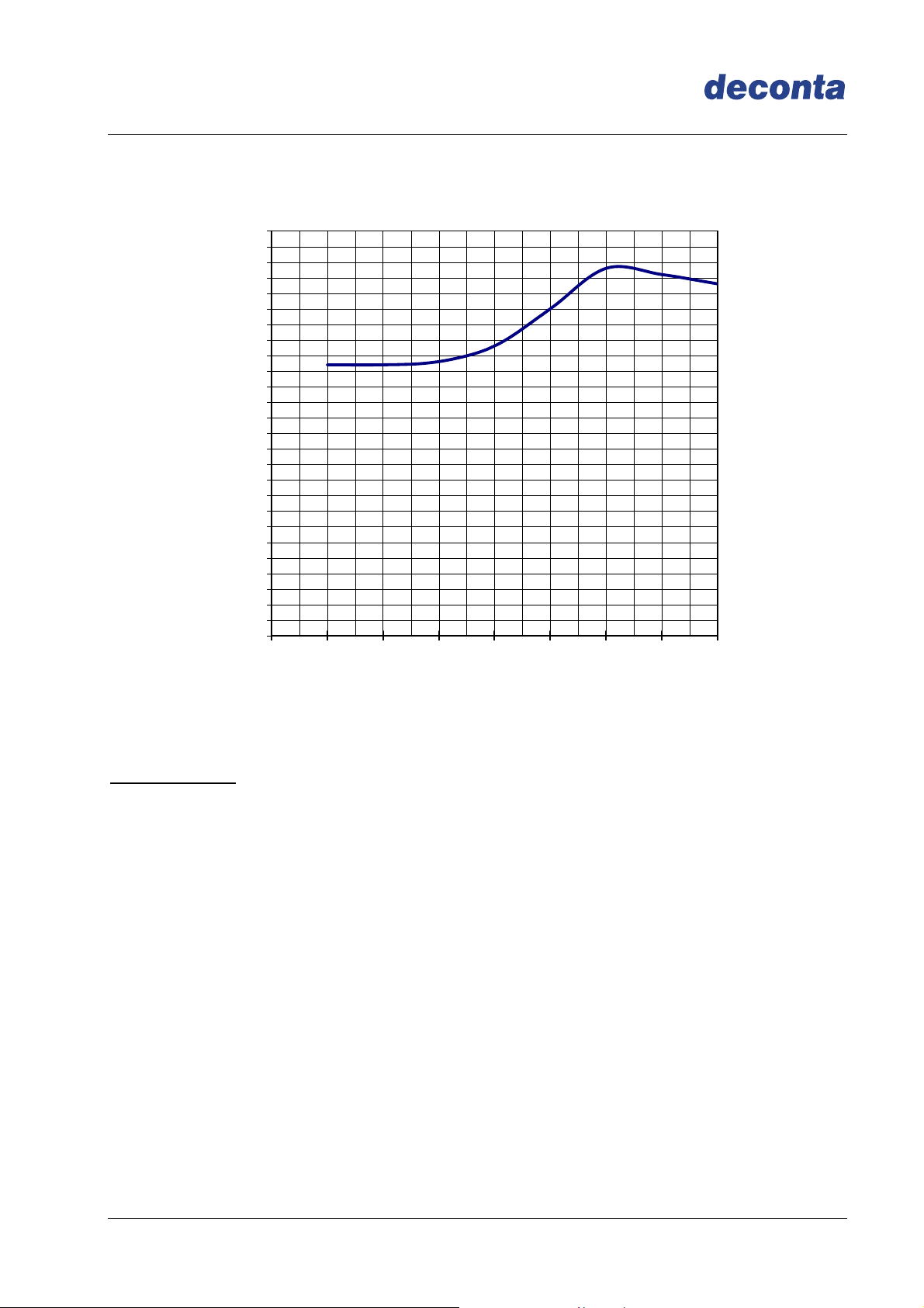
5.3 Fan characteristic curve D 305
1300
1250
1200
1150
1100
1050
1000
950
900
850
800
750
700
650
600
550
500
450
400
350
stat. Pressure boosting PA =>
300
250
200
150
100
50
0
0 350 400 500 700 1000 1500 2000 2200
olume flow V m³/h =>
Technical data:
Voltage: 230 V
Frequency: 50 Hz
Speed: 2850 U/min
Air discharge: 2400 m³/h free exhaust
max. discharge temperature: 45°C
Page 15

Negative Pressure Unit D-range
Instruction manual
5.4 Fan characteristic curve D 610
1800
1700
1600
1500
1400
1300
1200
1100
1000
900
800
700
600
500
stat. Pressure boosting PA =>
400
300
200
100
0
300 400 500 700 1000 2000 3000 4000 5000 7000
Volume flow in m³/h =>
Technical data:
Voltage: 230 V
Frequency: 50 Hz
Speed: 2800 U/min
Air discharge: 6000 m³/h free exhausting
max. discharge temperature: 45°C
Page 16

Negative Pressure Unit D-range
Instruction manual
5.5 Fan characteristic curve D 910
2000
1900
1800
1700
1600
1500
1400
1300
1200
1100
1000
900
800
700
600
500
stat. Pressure boosting PA =>
400
300
200
100
0
300 400 500 700 1000 2000 3000 4000 5000 6000 7000 8000
Volume flow in m³/h =>
Technical data:
Voltage: 230 V
Frequency: 50 Hz
Speed: 2780 U/min
Air discharge: 7500 m³/h free exhausting
max. discharge temperature: 45°C
Page 17

Negative Pressure Unit D-range
Instruction manual
5.6 Fan characteristic curve D 1200
3000
2500
2000
1500
1000
stat. Pressure boosting PA =>
500
0
1000 2000 3000 4000 5000 6000 7000 8000 9000 10000 11000 12000 13000 14000
Volume flow in m³/h =>
Technical data:
Voltage: 400 V
Frequency: 50 Hz
Speed: 2900 U/min
Air discharge: 15000 m³/h free exhausting
max. discharge temperature: 45°C
Page 18

Negative Pressure Unit D-range
Instruction manual
5.7 Power data
D 60 E D 60 D100 D305 D 610 D 910 D 1200
Air power free
blowing in m³/h
Air power with filter
in m³/h
Power connection
in Volt
980 1200 2400 6000 7500 15000
600 900 2000 4500 6000 12000
230 400
Current
consumption
1 4 9 16 16 16
in Ampere
Engine power
in kW
0,17 0,55 1,5 3 3 7,5
Filter system 2-steps 3-steps
Pre-filter ----- EU 3
Intermediate filter EU 4
Hepa filter According to EN 1822 classification H13
5.8 Connections, dimensions, weights
Hose connection
exhaust
Hose connection
Suction
D 60 E D 60 D100 D305 D 610 D 910
----- 150 150 300
optional
-----
4x 100
or
1x 150
optional
1x 300
400
450
optional
400
450
450 2x 450 450
optional
2x 450
Fan unit
2x 450
D 1200
Filter unit
FG 5
optional
2x 450
Length in mm
Width in mm
Height in mm
Weight incl. filter
in kg
565 560 920 930 1020 1160 800 720
440 400 420 690 725 880 720
440 400 840 850 1140 945 1150
21 19,5 24 45 95 116
116
(no FG 5)
70
Page 19

Negative Pressure Unit D-range
Instruction manual
5.9 Power loss in hose lines
Following factors have adverse influence:
Hose lines too long
Bends and bows in the hose lines
Cross-section narrowing of the hose lines.
5.10 Resistance diagram for hose lines
Hose line with external spiral
Sleeky inside
in 10 mtr. Length
Page 20

Negative Pressure Unit D-range
Instruction manual
6 Assembly instructions
The negative pressure unit is delivered ex-works and ready for immediate operation.
If there are visible damages, do not operate the device.
Please contact the deconta GmbH at once.
6.1 Assembly instructions with the example of D 610
(the procedure for D 60, D 100, D 305 and D 910 is identical)
Please respect:
Basically the negative pressure units D 60, D 100, D 305, D 610 and D 910 can also
be operated directly in the dirty area (over pressure technique prevent the
infiltration of the surrounding contaminated air in the housing).
Because the devices are contaminated from outside and therefore need an
expensive cleaning after the end of the sanitation work, one should avoid the use
in the dirty area by all means.
Connect the device with the wall between clean / and sanitation area
Place it about. 100 mm in the sanitation area
Seal the device with the wall
Conduct the exhausted air hose in the open air
Provide for enough supply air in the sanitation area
Clean area
Contaminated area
Supply air opening with
self-closing flaps
Page 21

Negative Pressure Unit D-range
Instruction manual
6.2 Assembly with the example of D 1200
Exit flange
Transport lid 2
Transport lid 2
Transport lid 1
Exit flange
Place the filter unit at approximately 100 mm in sanitation area and fix it
Seal the filter unit with the wall
Remove the transport lid (Pos.2) of the ventilator unit by unscrewing the wing bolt
Remove suction flange fixed to the filter housing for the transport and fix them by
means of 4 wing nuts to the ventilator unit
Screw the transport lids (Pos. 2) on the filter unit in order not to loose them
Connect the filter units and ventilator unit with the hoses
Conduct the supply air hose in the open air
Care for enough supply air in the sanitation area
Remove the transport lid (Pos.1) of the filter unit
Page 22

Negative Pressure Unit D-range
Instruction manual
Sanitation
area
Clean area
Exhaust hose
Attention:
Connect the filter housings according to the draft with the ventilation unit and let
rise up about 100mm in the sanitation area
Page 23

Negative Pressure Unit D-range
Instruction manual
6.3 Assembly of the optional attachment housing (SNAP) following the example of
D 610
Optionally for a second hepa filter (Double filtration), additional activated carbon filter or
pocket filter
Dismount the prefilter and unscrew the security corners (if existing)
Safety corners
Place the attachment housing and fix the tension locks
Tension lock
Insert the Hepa filter / activated carbon filter
Fix the tension frame by means of screws
Insert the pre-filter
By using an activated carbon filter, this should be inserted in the negative pressure unit and the
hepa-filter in the attachment housing.
Page 24

Negative Pressure Unit D-range
Instruction manual
7 Initial operation
7.1 Control ON / OFF
The negative pressure unit D 610 is delivered in series with an ON / OFF switch.
Connect with the current
Switch the ON / OFF switch
7.1.1 Negative pressurisation
Adjust the wished negative pressure at the supply air opening
Negative pressure too high: open the supply air opening
Negative pressure too low: shut the supply air opening
7.2 Control SE
For the power regulation, the negative pressure unit is delivered in series with a manual
continuous variable control.
Connect with the current
Operate the adjuster
7.2.1 Maintenance of the negative pressure in the room
Adjust the wished negative pressure at the supply air opening or the continuous
variable adjuster
Negative pressure too high: open the supply air opening or decrease the
device
Negative pressure too low: shut the supply air opening or increase the
device
Page 25

Negative Pressure Unit D-range
Instruction manual
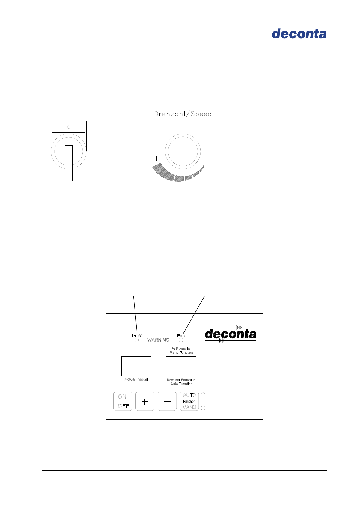
7.3 Control SRE
For the power regulation the negative pressure unit is delivered in series with an
electronic control, in order to measure and to regulate the negative pressure. The
negative pressure is measured between the dirty area and at a reference point to be
determined. In order to secure the adjusted values, the control is locked.
A LED Fan will beam on reaching the maximal fan capacity,
A LED Filter will beam if it is necessary to change the filter
Control panel:
LED „Filter“
LED „Fan“
Indication 1
Key „ON/OFF“
Key„+“
Indication 2
Key „AUTO/MANU“
Key „-“
Page 26

p
g
Negative Pressure Unit D-range
Instruction manual
Starting position:
Connect to the current
Chose a measuring point in the dirty area and connect the PE-tube 8 x 1 to the
negative pressure connection
Chose the measuring point in the clean area (adjoining room) and connect the PE-
tube 8 x 1 to the connection atmosphere
Connection
Atmos
here
connection
ative pressure
ne
The device is now ready for use. The last memorized negative pressure value will be
adjusted automatically. In order to change this value, you may procede as follow:
Activate the key ON/OFF
Chose the operation mode key AUTO/MANU
Automatic - operation
The reference value in automatic – operation is set with the keys - and + in Steps of
one Pascal (reference value in the display Thank2).
Thanks to the speed control of the ventilator, the negative pressure is regulated at once
automatically.
In the display 1 you can see the actual negative pressure.
Page 27

Negative Pressure Unit D-range
Instruction manual
Manual - operation
In manual operation the power of the ventilator is given with the keys - and + in
maximum 7 steps. The display 2 represents this value in %
In the display 1 you can see which negative pressure is created with the adjusted power.
Important:
Im „Manual“ operation, the device does not regulate!
8 Maintenance
8.1 Maintenace
The ventilator plants (deduster, industrial vaccum cleaners and devices for the
deaeration or kipping in negative pressure) have to be overhauled or controlled once a
year at least or if necessary by an expert.
8.2 Filter control
During the operation the filter state has to be controlled as described under 4.7.
Page 28

Negative Pressure Unit D-range
Instruction manual
8.3 Change of filter
Attention:
Contaminated filters have to be changed under all corresponding safety
measures
Filter change only with a machine sw itched off
Use approved filters only
Do not use bonding agents on the machine
Remove the hepa-filter:
Remove the prefilter
Unscrew the hexagone screws M8 and remove the tension frame
Remove the hepafilter and dispose of it professionally
Insertion of the hepa-filter:
Control the sealing face of the machine and clean.
Clean the inside of the housingI
Insert the new filter in the middle
Tighten the tension frame and the hexagone screws M8 (tighten the screws carefully)
Insert the pre-filter
Important:
Treat the hepafilter with care because otherwise damages can suspend the
effectivity of the filtration.
Page 29

Negative Pressure Unit D-range
Instruction manual
9 Possible failures and their repairs
Failure Possible reason Repair
Negative pressure
too low
Device does not
work
Device does not
work
Pre- / intermediate filters
dirty
Current source not correct
Parts of the negative
pressure unit defective
Change the filters as described under
8.3
Have power source examined and repaired
by an expert.
Have the device repaired by deconta
or an accredited workshop.
Page 30

Negative Pressure Unit D-range
Instruction manual
10 Circuit diagrams
10.1 Circuit diagram D 60 E
Page 31

Negative Pressure Unit D-range
Instruction manual
10.2 Circuit diagram D 60 SE
Page 32

Negative Pressure Unit D-range
Instruction manual
10.3 Circuit diagram D 100 ON / OFF
Page 33

Negative Pressure Unit D-range
Instruction manual
10.4 Circuit diagram D 100 SE
Page 34

Negative Pressure Unit D-range
Instruction manual
10.5 Circuit diagram D 100 SRE
Page 35

Negative Pressure Unit D-range
Instruction manual
10.6 Circuit diagram D 305 ON / OFF
Page 36

Negative Pressure Unit D-range
Instruction manual
10.7 Circuit diagram D 305 SE
Page 37

Negative Pressure Unit D-range
Instruction manual
10.8 Circuit diagram D 305 SRE
Page 38

Negative Pressure Unit D-range
Instruction manual
10.9 Circuit diagram D 610 ON / OFF
Page 39

Negative Pressure Unit D-range
Instruction manual
10.10 Circuit diagram D 610 SE
Page 40

Negative Pressure Unit D-range
Instruction manual
10.11 Circuit diagram D 610 SRE
Page 41

Negative Pressure Unit D-range
Instruction manual
10.12 Circuit diagram D 910 SE
Page 42

Negative Pressure Unit D-range
Instruction manual
10.13 Circuit diagram D 910 SRE
Page 43

Negative Pressure Unit D-range
Instruction manual
10.14 Circuit diagram D 1200 SE
Page 44

Negative Pressure Unit D-range
Instruction manual
10.15 Circuit diagram D 1200 SRE
Page 45

Negative Pressure Unit D-range
Instruction manual
11 Sound level measuring
Status:
Engine power 100%, outside
Device A1 A2 A3 A4 A5 B1 B2 B3 B4 B5 C1 C2 C3 C4 C5 D1 D2 D3 D4 D5
D 60 E 68 65 62 60 58 66 65 64 63 63 63 59 57 56 56 63 59 57 56 56
D 60 68 65 62 60 58 66 65 64 63 63 63 59 57 56 56 63 59 57 56 56
D 100 69 65 63 61 58 70 65 63 61 59 65 63 60 58 57 65 63 60 58 57
D 305 72 69 66 64 62 79 74 70 68 66 70 66 63 61 59 70 66 63 61 59
D 610 80 78 77 75 72 85 82 78 76 73 80 77 74 71 70 80 77 74 71 70
D 910 82 78 73 71 70 82 78 74 72 71 75 72 69 68 68 75 72 69 68 68
D 1200 85 81 81 78 76 80 76 74 72 69 80 75 72 70 69 80 75 72 70 69
Value in dB (A)
The setting of a silencer reduces the sound level in due consideration of a loss of power.
Page 46

Negative Pressure Unit D-range
Instruction manual
12 Declaration of conformity
EU Declaration of Conformity
deconta GmbH
Im Geer 20
D-46419 Isselburg
Product: Negative pressure unit Type: 411, 414, 415, 430, 431, 432, 450, 451,453,
454, 455, 456, 457, 458, 490, 491, 601, 620
The design of the units corresponds EU- Machine directive 98/37/EG
to the following regulations: EU- low-voltage directive 2006/95/EG
Applied harmonised standards: EN 60335-2-69
Applied national standards: DIN VDE 0701, DIN VDE 0702
W. Weßling Isselburg, 25.03.2015
The copyright of this instruction manual remains with deconta. This manual is intended
for assembly, operation and maintenance personnel. It contains instructions and drafts of
technical nature which may neither be distributed nor used in any unauthorised way for
competitive purposes or passed on to others.
For more information, please see our website www.deconta.com
Page 47
 Loading...