

deconta aircontrol S Series, aircontrol S 2, aircontrol S 3, aircontrol S 1 Instruction Manual
Instruction manual
Negative Pressure Monitor
aircontrol S 110V
Manufacturer: deconta GmbH
Im Geer 20, D - 46419 Isselburg
Description / Type No.: aircontrol S 1 110V Type 608
aircontrol S 2 110V Type 603
aircontrol S 3 110V Type 609
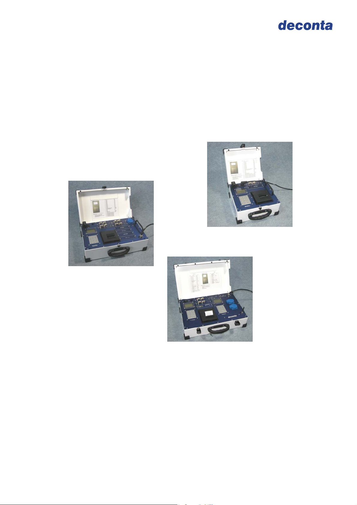
aircontrol S 2
aircontrol S 3
aircontrol S 1

Instruction manual
aircontrol S 110V
Table of contents
on page
1 Introduction 3
2 Basic safety advice 4
2.1 Intended use 4
2.2 Operation 4
3 Transport 5
3.1 Delivery 5
3.2 Transport 5
4 Scope of delivery 5
5 Technical description 6
6 Technical data 7
6.1 Technical data 7
6.2 Basic equipment and possible upgrades 7
6.3 Terminal assignment potential-free alarm contact 8
7 Initial operation 8
7.1 Telealarm GSM, inserting a Sim-Card 9
7.2 Standby function 10
8 Display-indication 11
8.1 aircontrol 11
8.2 Telealarm 12
9 Settings / operation 13
9.1 Possible settings / Code chart aircontrol 14
9.2 Possible settings / Code chart Telealarm 15
10 Extension modules 16
10.1 Additional measuring channels 16
10.2 Printer module 16
10.3 Emergency battery 17
10.4 Measurement data memory module 18
11 Declaration of conformity 20
page 2

Instruction manual
aircontrol S 110V
1 Introduction
Thank you for selecting a deconta product.
With this device you obtain a practical solution with simple operation, which was
completed in a compact and functional way.
The deconta products guarantee:
Stability, long life and serviceability on site
Mechanics with „kick“
Pleasing design
The copyright of this instruction manual remains with deconta. This manual is intended
for assembly, operation and maintenance personnel. It contains instructions and drafts of
technical nature which may neither be distributed nor used in any unauthorised way for
competitive purposes or passed on to others.
For more information, please visit our website www.deconta.com
page 3

Instruction manual
aircontrol S 110V
2 Basic safety advice
The handling of the appliance technology is only allowed for instructed staff. The exact
knowledge of the instruction manual is an important condition for your staff in regard to
the handling of the machine.
2.1 Intended use
As an operator, you are obliged by deconta to follow the instruction manual and to use
this engineered technology equipment only in accordance with the regulations and its
suitability! In the event of non-observance, deconta assumes no liability.
2.2 Operation
In order to ensure the safety during the operation of the device, the following must be
observed:
Do not place in an explosive area
Necessary repairs, maintenance and cleaning, in particular in the field of electrical
equipment has to be realized only by qualified staff
The safety and protective equipment has to be kept in perfect functioning.
Attached safety instructions have to be kept in a readable state and have to be
followed.
In order to ensure safety, any changes to the machine are prohibited.
ATTENTION!
The device is not suitable for the use in a condensed, corrosive, flammable and
explosive compartment air. The ambient and medium air temperature must be
situated in a sector from -10 up to+50°C
Protect against moisture!
page 4

Instruction manual
aircontrol S 110V
3 Transport
3.1. Delivery
Unless agreed otherwise, the lock system is packed completely and securely for
transport by deconta. Transport damages have to be documented at once during the
handing over of the carrier or another supplier. Please note the possible damages
additionally on the way bill. To avoid damages caused by improper handling or
carelessness, it is common practice to handle the Transport with care.
3.2 Transport
In order to protect the device during the transport, it is located in a transport box.
Care must be taken to ensure the device is not exposed to impacts or blows, because
otherwise the function and safety of the device cannot be guaranteed.
4 Scope of delivery
If no other agreements have been made, the scope of delivery of a negative pressure
control device consists of:
Portable set
Power cable (only aircontrol S 1)
Short description
Instruction manual
page 5

Instruction manual
aircontrol S 110V
5 Technical description
The aircontrol S is designed to measure, document and react to alarm conditions in
regard to the Negative Pressure Monitoring.
The devices can be equipped with individual extension modules according to customer
requirements.
There are 3 different versions available. aircontrol S 1 offers space for 4 extension
modules, aircontrol S 2 offers space for 10 extension modules, aircontrol S 3 offers
space for 5 extension modules and is provided with an additional automatic telephone
device (Telealarm GSM), to initiate an alarm via the mobile phone network, as well as
with integrated connectible sockets for Standby-units.
For the calibration or service it is sufficient to change the concerned modules.
Thanks to the combination of an easy operation and high flexibility the aircontrol S
represents a powerful and future-proof measuring device for your site.
page 6

Instruction manual
aircontrol S 110V
6 Technical data
6.1 Technical data
Measurements in mm (L x W x H) 305 x 350 x 177 475 x 350 x 177 495 x 350 x 187
Weight 5,5 kg 7,9 kg 8,4 kg
Power connection 100-120 V / 16 A 100-120 V / 16 A 100-120 V / 16 A
Range of measurement 0 - 100 Pa 0 - 100 Pa 0 - 100 Pa
Pressure resistance Load cell max. 0,25 bar max. 0,25 bar max. 0,25 bar
Occupied extension slots 1 1 1
Free extension slots 4 10 5
6.2 Basic equipment and upgrades
S 1 S 2 S 3
S 1 S 2 S 3
Powder coated lockable housing
Large display with light
Keyboard vandal-proof
Dry alarm contact (e.g. for external Telealarm
GSM)
Alarm plug 100-120 V / 16 A
Connectible socket 100-120 V / 16 A for
Standby-units
Measuring connec tion for tube 8 x 1 mm
1 piece measuring channel
Telealarm GSM integrated
Additional measuring channels
Printer module (occupies 3 extension slots) O O O BE2326
Emergency-battery (occupies no extension
slot)
Measuring data memory module O O O BE2328
O
(max. 4) O (max. 7) O (max. 5)
O
Art.-No.
BE2324
BE2327
= standard O = optional = not possible
page 7

Instruction manual
3
aircontrol S 110V
6.3 Terminal assignment dry alarm contact (only aircontrol S 1 und S 2)
PE
1
2
In normal condition: contact 1 and 2 open, contact 1 and 3 closed
In alarm condition: contact 1 und 2 closed, contact 1 and 3 open
Without main voltage: contact 1 and 2 closed, contact 1 and 3 open
7 Initial operation
Important instructions:
Before every use, please check the device, cable and plug for damages.
In the event of malfunction, you have to stop the device at once and secure it.
Have the malfunctions repaired immediately.
The device and their electrical connections may not get wet or be operated in a
humid environment
The screw caps of the measuring and reference connections have to be screwed
down tightly.
The measuring tubes may not be flexed or damaged.
Do not place the measuring tube in an area where they can be pressed together
Do not expose the reference connection to dynamic pressure ratios (e.g.: wind)
The device has to stand horizontally on an even surface.
Do not expose the device in operational state to any vibrations or shocks.
Short tube lengths shorten the response time of the measuring device.
By measuring tube lengths over 150 m, tubes with bigger diameter should be
used.
The pressure on the measuring connections must not exceed 0,1 bar (10.000 Pa),
because otherwise the device can be damaged. Never blow inside of it, suck or
Starting position:
impinge it with other pressures!
Connect negative pressure areas with measuring tubes to the device
„connection -“
Choose the reference measuring point and connect through measuring tube to the
device „connection +“.
Turn on the instrument
page 8

Instruction manual
aircontrol S 110V
Important: Rooms adjoining to the area of operations have to be chosen as reference
measuring points. A configuration of the reference measuring point can be cancelled, if
the Negative Pressure Monitor is placed at the location of the reference measuring point.
Attention: Never use the Negative Pressure Monitor in the
contaminated work area!
7.1 Telealarm GSM, inserting of Sim-Card (only aircontrol S 3)
If the Sim-Card is protected by a PIN-Number, this Number must be saved in the
Telealarm before the Sim-Card is inserted. (Enter #20, see Code-chart).
Switch-off unit and pull power plug.
Loosen screws of protective cover and take off cover.
Press on the yellow button with a sharp-pointed object, e.g.
ballpoint pen. Push out the Sim-Card-Holder and remove from
slot.
Insert Sim-Card into Holder. Ensure that the chamfered
corner is in the correct position.
Reinsert Sim-Card-Holder. Ensure the correct installation
position of the Sim-Card-Holder.
Replace protective cover.
page 9

Instruction manual
aircontrol S 110V
7.2 Standby Function (only aircontrol S 3)
The Standby Function is activated via a Code-Entry (Code-chart aircontrol, Code 60).
As soon as the Negative Pressure Monitor aircontrol notices a negative pressure in the
removal area that is too low (constant alarm via X seconds, adjustable at aircontrol), an
integrated Standby-mode is activated.
The Standby-Negative pressure unit is supplied with power by its connection to one of
the blue sockets.
After the completion of the alarm the Standby-Negative pressure unit keeps on running
and is switched off via a code-entry (Code-chart, aircontrol, Code 61) only after the cause
of alarm is clarified and resolved.
page 10

Instruction manual
aircontrol S 110V
8 Display-indication
8.1 aircontrol
Time
Device status
Dynanometer(1 – 8)
Measuring value
After switching on the aircontrol there are 3 information displayed in the top line:
Top left => device status
Possible status indications (S followed by 3 numbers):
First digit 1 to 8 Number of the present measuring channels
Second digit 1 Optional printer present
Second digit 2 Optional memory module present
Second digit 3 Printer and memory modules present
Third digit 1 Optional communication module present
Top middle => Actual time
Top right => Alarm status
Possible alarm status indications:
A100 Alarm evaluation deactivated
A101 Alarm evaluation is activated, no alarm has been identified
A102 Alarm low identified, the delay time is running
103 Alarm high identified, the delay time is running
A104 External alarm identified, the delay time is running
A112 Alarm low identified, the delay time has expired
A113 Alarm high identified, the delay time has expired
A114 External alarm identified, the delay time has expired.
Underneath the top line, the dynamometer is displayed with the actual measured
negative pressure values.
Indication for inserted
options (e.g. battery)
Alarm status
page 11

Instruction manual
aircontrol S 110V
8.2 Telealarm (only aircontrol S 3)
Network operator
Device status
Charging indicator
(battery)
Alarm status
GSM- field strength
After switching on the aircontrol there are 3 information displayed in the top line:
Top left => Device status
Possible status indicators (S followed by 3 numbers):
S500 Sim-Card is missing
S501 Sim-Card is invalid
S502 No GSM-Network available
S503 PIN-Number is wrong
S504 GSM-Network available, but not logged in
S505 Searching for available GSM-Network
S510 home network logged in GSM-Network
S511 logged in GSM-Network, Roaming
Top right => Alarm status
Possible Alarm status indicators:
A100 Alarm analysis deactivated
A101 Alarm analysis is activated, no alarm detected
A102 Alarm detected, delay time is running
A103 Delay time is expired, Call is effected
A104 Calls have been executed
Middle => Name or Number of Network operator
Bottom left => GSM-Field strength with 0 to 5 bars
page 12

Instruction manual
aircontrol S 110V
9 Settings / Operation
Adjustments are always carried out according to the same procedure via the keypad:
Push the key # => C will appear on the display
Enter the code for the relevant adjustment (see following Code-chart)
Push the key # => The actual adjusted value is indicated
Enter a new value
Confirm the entry with the key #
page 13

Instruction manual
aircontrol S 110V
9.1 Possible adjustments / Code-chart aircontrol
Code Function Value
5 Activate / Inactivate Unit
11 Alarm low channel 1 0 - 290 Pa
12 Alarm low channel 2 0 - 290 Pa
13 Alarm low channel 3 0 - 290 Pa
14 Alarm low channel 4 0 - 290 Pa
15 Alarm low channel 5 0 - 290 Pa
16 Alarm low channel 6 0 - 290 Pa
17 Alarm low channel 7 0 - 290 Pa
18 Alarm low channel 8 0 - 290 Pa
21 Alarm high channel 1 0 - 300 Pa
22 Alarm high channel 2 0 - 300 Pa
23 Alarm high channel 3 0 - 300 Pa
24 Alarm high channel 4 0 - 300 Pa
25 Alarm high channel 5 0 - 300 Pa
26 Alarm high channel 6 0 - 300 Pa
27 Alarm high channel 7 0 - 300 Pa
28 Alarm high channel 8 0 - 300 Pa
30 Audible alarm signal switched off via key * for X minutes 0 - 240 minutes
31 Delayed switching alarm socket (only at S2/S3) 0 - 999 seconds
32 Delayed switching contact potential free (only at S1 / S2) 0 - 999 seconds
40 Time in hours 00 - 23
41 Time in minutes 00 - 59
42 Date day 00 - 31
43 Date month 01 - 12
44 Date year 00 - 99
50 Print out every X minutes, 0=off 0 - 240 minutes
51 Memory interval all X minutes 1 - 240 minutes
52
53 Memory delete
60 Switching status alarm socket after alarm (only at S 3)
61 Reset after alarm (only at S 3) 0 = Reset
62 Alarm socket manually (only at S 3)
801 Channel 1, indication of the dynamometer number and date of calibration
802 Channel 2, indication of the dynamometer number and date of calibration
803 Channel 3, indication of the dynamometer number and date of calibration
804 Channel 4, indication of the dynamometer number and date of calibration
805 Channel 5, indication of the dynamometer number and date of calibration
806 Channel 6, indication of the dynamometer number and date of calibration
807 Channel 7, indication of the dynamometer number and date of calibration
808 Channel 8, indication of the dynamometer number and date of calibration
Number of memory data sets, which should be transferred
on a USB-Stick
0 = inactive
1 = active
0 – 9998
0 = cancel
1 = delete
0 = inactive
1 = active
0 = inactive
1 = active
page 14

Instruction manual
aircontrol S 110V
9.2 Possible adjustments / Code-chart Telealarm (only aircontrol S 3)
Code Function Value
1
2 Listen to announcement
5 Activate / inactivate unit
11 Phone number 1
12 Phone number 2
13 Phone number 3
14 Phone number 4
15 Phone number 5
19 Delete all saved phone numbers
20 PIN-Number of Sim-Card 4-digit
31 Delay time alarm message 0 - 999 seconds
40 Number of redials 0 - 9
Recording of message (record text via
microphone, max. 20 seconds)
0 = inavtive
1 = active
0 = cancel
1 = delete
41 Time in between redials 0 - 999 seconds
42 Stop dialling after receipt of call
0 = after first contact
1 = choose all numbers
Note:
To delete a recorded message, a new message without text must be recorded.
Possible approach:
Press key #
Enter 1
Press key # 2x twice in succession
page 15

Instruction manual
aircontrol S 110V
10 Extension modules
aircontrol S 1 offers space for 4 extension modules, aircontrol S 2 offers space for 10
extension modules and aircontrol S 3 offers space for 5 more extension modules.
10.1 Additional measuring channels
For the aircontrol S 1, 4 more measuring channels can be upgraded or managed, in
addition to the existing measuring channel
For the aircontrol S 2, 7 more measuring channels can be upgraded or managed, in
addition to the existing measuring channel
For the aircontrol S 3, 5 more measuring channels can be upgraded or managed, in
addition to the existing measuring channel
10.2 Printer module (occupies 3 free extension slots)
With the help of the printer module, the measuring values can be recorded and
documented (archive-safe on normal paper rolls).
Change of paper and ink ribbon
Paper roll
Art.-No. AU1073
Green button
Push
Ink ribbon
Art.-No. AU1072
Change of paper roll
Open the black printer cover
Pull out the empty paper roll and exchange
Insert the bottom of the paper in the printer, at the same time press the green key
page 16

Instruction manual
aircontrol S 110V
When the top of the paper comes out, release the green key.
Insert the top of the paper through the slot of the printer cover
Shut the printer cover
Changing of ink ribbon:
Cut unit from the mains
Open printer cover
Push on the field marked „Push“
The ribbon comes off
Change the ribbon
10.3 Emergency battery (only for aircontrol S 2 / S 3, occupies no slots)
When battery is fully charged the Negative Pressure Monitor can maintain the measuring
during a period of approx. 2-3 h without power supply. In battery mode the display
backlight and the printer module are switched off. An indication regarding the battery
mode is printed by the printer.
page 17

Instruction manual
g
aircontrol S 110V
10.4 Measuring data-memory module (from Software version 1.3)
Saving of the measuring data (max. 90000 Data sets) with adjustable memory intervals.
Export as txt-Data for further treatment via USB-Stick. The USB-Stick must be
formatted as FAT or FAT 32. If the maximal capacity of memory is exceeded, the oldest
data sets are overwritten.
The content of the raw txt file looks like this:
29.04.10 08:29 #1 24 #2 22 #3 14 #4 12 #5 0 #6 0 #7 0 #8 0
29.04.10 07:59 #1 22 #2 23 #3 12 #4 13 #5 0 #6 0 #7 0 #8 0
29.04.10 07:29 #1 23 #2 22 #3 13 #4 11 #5 0 #6 0 #7 0 #8 0
29.04.10 06:59 #1 21 #2 24 #3 13 #4 13 #5 0 #6 0 #7 0 #8 0
29.04.10 06:29 #1 22 #2 26 #3 14 #4 12 #5 0 #6 0 #7 0 #8 0
29.04.10 05:29 #1 24 #2 27 #3 12 #4 12 #5 0 #6 0 #7 0 #8 0
29.04.10 04:29 #1 23 #2 28 #3 13 #4 12 #5 0 #6 0 #7 0 #8 0
29.04.10 03:29 #1 23 #2 29 #3 15 #4 11 #5 0 #6 0 #7 0 #8 0
29.04.10 02:29 #1 24 #2 25 #3 15 #4 11 #5 0 #6 0 #7 0 #8 0
29.04.10 01:29 #1 26 #2 25 #3 17 #4 13 #5 0 #6 0 #7 0 #8 0
29.04.10 00:29 #1 25 #2 26 #3 16 #4 12 #5 0 #6 0 #7 0 #8 0
28.04.10 23:29 #1 24 #2 24 #3 13 #4 12 #5 0 #6 0 #7 0 #8 0
28.04.10 22:29 #1 23 #2 27 #3 13 #4 11 #5 0 #6 0 #7 0 #8 0
28.04.10 21:29 #1 25 #2 24 #3 14 #4 11 #5 0 #6 0 #7 0 #8 0
28.04.10 20:29 #1 22 #2 24 #3 14 #4 13 #5 0 #6 0 #7 0 #8 0
28.04.10 19:29 #1 21 #2 24 #3 15 #4 13 #5 0 #6 0 #7 0 #8 0
28.04.10 18:29 #1 22 #2 26 #3 13 #4 12 #5 0 #6 0 #7 0 #8 0
28.04.10 17:29 #1 24 #2 23 #3 12 #4 11 #5 0 #6 0 #7 0 #8 0
28.04.10 16:29 #1 22 #2 24 #3 16 #4 13 #5 0 #6 0 #7 0 #8 0
28.04.10 15:29 #1 24 #2 24 #3 15 #4 12 #5 0 #6 0 #7 0 #8 0
28.04.10 14:29 #1 25 #2 25 #3 14 #4 11 #5 0 #6 0 #7 0 #8 0
28.04.10 13:29 #1 26 #2 27 #3 12 #4 13 #5 0 #6 0 #7 0 #8 0
28.04.10 12:29 #1A 17 #2 26 #3 12 #4 12 #5 0 #6 0 #7 0 #8 0
28.04.10 12:17 #1 28 #2 21 #3 13 #4 13 #5 0 #6 0 #7 0 #8 0
28.04.10 11:17 #1 23 #2 21 #3 12 #4 13 #5 0 #6 0 #7 0 #8 0
28.04.10 10:17 #1 22 #2 26 #3 13 #4 11 #5 0 #6 0 #7 0 #8 0
28.04.10 09:17 #1 25 #2 24 #3 14 #4 12 #5 0 #6 0 #7 0 #8 0
28.04.10 08:17 #1 22 #2 25 #3 15 #4 12 #5 0 #6 0 #7 0 #8 0
28.04.10 07:17 #1 23 #2 26 #3 15 #4 12 #5 0 #6 0 #7 0 #8 0
28.04.10 06:17 #1 24 #2 23 #3 13 #4 11 #5 0 #6 0 #7 0 #8 0
28.04.10 05:17 #1 23 #2 23 #3 14 #4 12 #5 0 #6 0 #7 0 #8 0
28.04.10 04:17 #1 25 #2 24 #3 12 #4 13 #5 0 #6 0 #7 0 #8 0
Date
Time
Measuring channel 1
Channel 1 measured
ative pressure in Pa
ne
Alarm, marked by „A“ behind the
measuring channel
page 18

Instruction manual
aircontrol S 110V
The file containing the saved data can be edited freely using a text editor.
Example:
Project: Munich
Bauleitung: Mr. Mustermann
Measuring device: aircontrol S2 Type: 481 Series: 583
Removal period: 27.04.2010 08:00 to 29.04.2010 08:29
Channel 1: Working area 1 Setting: min. 20Pa – max. 50Pa
Channel 2: Working area 2 Setting: min. 20Pa – max. 50Pa
Channel 3: Personnel lock Setting: min. 10Pa – max. 19Pa
Channel 4: Material lock Setting: min. 10Pa – max. 19Pa
Channel 5 to channel 8 not occupied
29.04.10 08:29 #1 24 #2 22 #3 14 #4 12 #5 0 #6 0 #7 0 #8 0
29.04.10 07:59 #1 22 #2 23 #3 12 #4 13 #5 0 #6 0 #7 0 #8 0
29.04.10 07:29 #1 23 #2 22 #3 13 #4 11 #5 0 #6 0 #7 0 #8 0
29.04.10 06:59 #1 21 #2 24 #3 13 #4 13 #5 0 #6 0 #7 0 #8 0
29.04.10 06:29 #1 22 #2 26 #3 14 #4 12 #5 0 #6 0 #7 0 #8 0
29.04.10 05:29 #1 24 #2 27 #3 12 #4 12 #5 0 #6 0 #7 0 #8 0
29.04.10 04:29 #1 23 #2 28 #3 13 #4 12 #5 0 #6 0 #7 0 #8 0
29.04.10 03:29 #1 23 #2 29 #3 15 #4 11 #5 0 #6 0 #7 0 #8 0
29.04.10 02:29 #1 24 #2 25 #3 15 #4 11 #5 0 #6 0 #7 0 #8 0
29.04.10 01:29 #1 26 #2 25 #3 17 #4 13 #5 0 #6 0 #7 0 #8 0
29.04.10 00:29 #1 25 #2 26 #3 16 #4 12 #5 0 #6 0 #7 0 #8 0
28.04.10 23:29 #1 24 #2 24 #3 13 #4 12 #5 0 #6 0 #7 0 #8 0
28.04.10 22:29 #1 23 #2 27 #3 13 #4 11 #5 0 #6 0 #7 0 #8 0
28.04.10 21:29 #1 25 #2 24 #3 14 #4 11 #5 0 #6 0 #7 0 #8 0
28.04.10 20:29 #1 22 #2 24 #3 14 #4 13 #5 0 #6 0 #7 0 #8 0
28.04.10 19:29 #1 21 #2 24 #3 15 #4 13 #5 0 #6 0 #7 0 #8 0
28.04.10 18:29 #1 22 #2 26 #3 13 #4 12 #5 0 #6 0 #7 0 #8 0
28.04.10 17:29 #1 24 #2 23 #3 12 #4 11 #5 0 #6 0 #7 0 #8 0
28.04.10 16:29 #1 22 #2 24 #3 16 #4 13 #5 0 #6 0 #7 0 #8 0
28.04.10 15:29 #1 24 #2 24 #3 15 #4 12 #5 0 #6 0 #7 0 #8 0
28.04.10 14:29 #1 25 #2 25 #3 14 #4 11 #5 0 #6 0 #7 0 #8 0
28.04.10 13:29 #1 26 #2 27 #3 12 #4 13 #5 0 #6 0 #7 0 #8 0
28.04.10 12:29 #1A 17 #2 26 #3 12 #4 12 #5 0 #6 0 #7 0 #8 0
28.04.10 12:17 #1 28 #2 21 #3 13 #4 13 #5 0 #6 0 #7 0 #8 0
28.04.10 11:17 #1 23 #2 21 #3 12 #4 13 #5 0 #6 0 #7 0 #8 0
28.04.10 10:17 #1 22 #2 26 #3 13 #4 11 #5 0 #6 0 #7 0 #8 0
28.04.10 09:17 #1 25 #2 24 #3 14 #4 12 #5 0 #6 0 #7 0 #8 0
28.04.10 08:17 #1 22 #2 25 #3 15 #4 12 #5 0 #6 0 #7 0 #8 0
28.04.10 07:17 #1 23 #2 26 #3 15 #4 12 #5 0 #6 0 #7 0 #8 0
28.04.10 06:17 #1 24 #2 23 #3 13 #4 11 #5 0 #6 0 #7 0 #8 0
28.04.10 05:17 #1 23 #2 23 #3 14 #4 12 #5 0 #6 0 #7 0 #8 0
28.04.10 04:17 #1 25 #2 24 #3 12 #4 13 #5 0 #6 0 #7 0 #8 0
page 19

Instruction manual
aircontrol S 110V
11 Declaration of conformity
EU Declaration of Conformity
deconta GmbH
Im Geer 20
D-46419 Isselburg
Product: Negative Pressure Monitor Type: 603, 608, 609
The design of the units complies with the EU- Machine directive2006/42/EG
following directives: EU- Low voltage directive2006/95/EG
EU- Directive89/336/EWG
Applied harmonised standards: EN 60335-1
Applied national standards : DIN VDE 0701, DIN VDE 0702
W.Weßling Isselburg, 10.04.2013
page 20
 Loading...