

decon E-Drive PLUS Service Manual

4FSWJDFmanual
E-Drive PLUS
#SVLBSNBOVBMWFSTJPO

Foreword
NOTICE
WARNING
This Service Manual describes the procedures for inspecting, adjusting, and assembling the E-Drive PLUS,
as well as how to handle errors.
Symbols Used in This Manual
Items concerning proper handling are indicated with the following symbols.
Indicates that misuse may lead to fatal or severe injury, or
disability.
Indicates that misuse may lead to material damage.
Indicates correct methods and key points when operating the
product.
Other Precautions
• For product improvement purposes, the descriptions and specifications in this manual are
subject to change without notice.
• Due to changes in the specifications, some of the photos and descriptions may differ from
the actual product.
• This manual is intended for use by persons possessing the basic technical knowledge and
skills.
• Persons who do not possess the general service skills and knowledge should not rely solely
on this service manual to perform inspection, adjustment, disassembly, or reassembly.
Failure to observe this precaution can lead to maintenance problems or mechanical dam-
age.

Table of Contents
1. Product Overview 5
1.1. Product Features 5
1.2. Variations 6
2.
Wheelchair Frame Conditions for Installing the E-Drive PLUS
2.1. Strength Conditions 7
2.2. Structure Conditions 7
2.3. Functional Conditions 8
2.4. Other 8
2.5. Assistant Controller 9
7
3. Installation Procedure 10
3.1. Supplied Parts Check 10
3.2. Power Unit Installation 17
3.3. Separate Battery Seat Installation 22
3.4. Controller Installation 23
3.5. Anti-tip Device Adjustment 31
3.6. Clutch Lever Position Adjustment 32
3.7. Wheel Cap Installation (20", 22" and 24" Models) 32
3.8. Check Items after Power Unit Installation 33
4.
5.
Optional Part Installation and Adjustment Procedures
4.1. Battery Seat Oset Parts 34
4.2. Joystick Knob and Return Spring Replacement 37
4.3. Power Switch and Speed Switch Replacement 41
4.4. Hand Rim Replacement (20", 22", and 24" Models) 43
4.5. Wheel Cap Replacement (20", 22", and 24" Models) 44
Installation, Removal, Disassembly, Assembly, and Adjustment Procedures of Each Part
5.1. Wheel Assembly Removal and Installation 46
5.2. Drive Unit Removal and Installation
(Fixed Axle Models) 47
5.3. Motor Control Unit (Printed Circuit Board) Removal
and Installation 48
34
46

5.4. Wire Harness and Lead Wire Removal
and Installation 50
5.5. Clutch Lever Removal and Installation
(20", 22" and 24" Models) 50
5.6. Clutch Switch Adjustment 52
5.7. Controller Removal, Installation, and Position
Adjustment 52
5.8. Switching the Controller Left/Right Side Position 54
5.9. Controller Disassembly, Assembly, and Parts
Replacement 57
5.10. Assistant Controller (Option) Disassembly
and Assembly 59
6. Settings the Parameters 60
6.1. Operation Overview 60
6.2. Driving Parameters ~Preset Mode~ Setting Method 63
6.3. Driving Parameters ~Free Mode~ Setting Method 65
6.4. Function Parameters Setting Method 73
6.5. Method for Restoring Factory Settings 77
7. Other Settings 78
7.1. Joystick Range of Motion Adjustment 78
7.2. Anti-tampering Function Setting 80
8. Warnings 82
8.1. List of Warnings 82
9. Self-Diagnosis 85
9.1. Self-Diagnosis Function 85
9.2. List of Detected Malfunctions 85
9.3. History Display of Detected Malfunctions Using the
Self-Diagnosis 91
10. Inspection and Maintenance 93
10.1. Inspection Item 93
11. Specications and Other Information 94
11.1. Table of Specications 94
11. 2. W i r i n g Diagram 98
1.
Product Overview
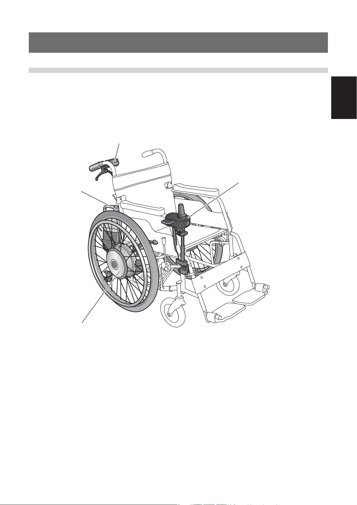
1.1. Product Features
Example of installed E-Drive PLUS
4
3
1
2
1
1 Drive unit with AC servo flat motor.
2 Joystick controller.
3 Dedicated battery with built-in microcomputer.
(Nickel metal hydride battery or lithium ion battery)
4 Assistant controller (optional)
5

1.2. Variations
(1) Power Unit for Wheelchairs
1
Model
Tire size 20", 22" and 24" 16"
Controller
Controller mounting
Speed
Mounting brackets
Battery seat
Battery location (when
using the integrated
battery seat)
Battery types
Left
Right
Standard
Swing out
4.5 km/h type
6.0 km/h type
Cramp bracket
Bracket A –
Bracket B –
Integrated
Separate –
No offset
Offset (28.5 mm)
Nickel metal hydride
battery
Lithium ion battery
{{
{{
{{
{{
{{
{{
{
{{
{{
{{
{{
{{
E-Drive PLUS
–
{
{
{
Assistant controller
(optional, right-hand
operation only)
Assistant controller
included
{{
6

2.
WARNING
Do not install the E-Drive PLUS on a wheelchair frame that has insufficient strength.
Do not install the E-Drive PLUS on a wheelchair frame that does not meet the installation condi-
tions. Even if it can be installed on the frame, it may malfunction during use if the conditions are
not met, which could injure the user.
Wheelchair Frame Conditions for Installing the E-Drive PLUS
2.1. Strength Conditions
In order to ensure that the entire wheelchair has sufficient strength, the wheelchair frame on which
the E-Drive PLUS is installed must meet the following conditions.
(1) It must have strength equivalent to that required by JIS standards (T9203).
(2) The axle sleeve bracket is securely installed and does not have any looseness.
(3) It must not have a camber angle.
(4) It must have sufficient strength. (There is the chance that wheelchair frames that have
been used for a long time will lose some of their strength.)
(5) It must not have a camber angle.
(6) It must have sufficient strength.
(There is the chance that wheelchair frames that have been used for a long time will lose
some of their strength.)
2
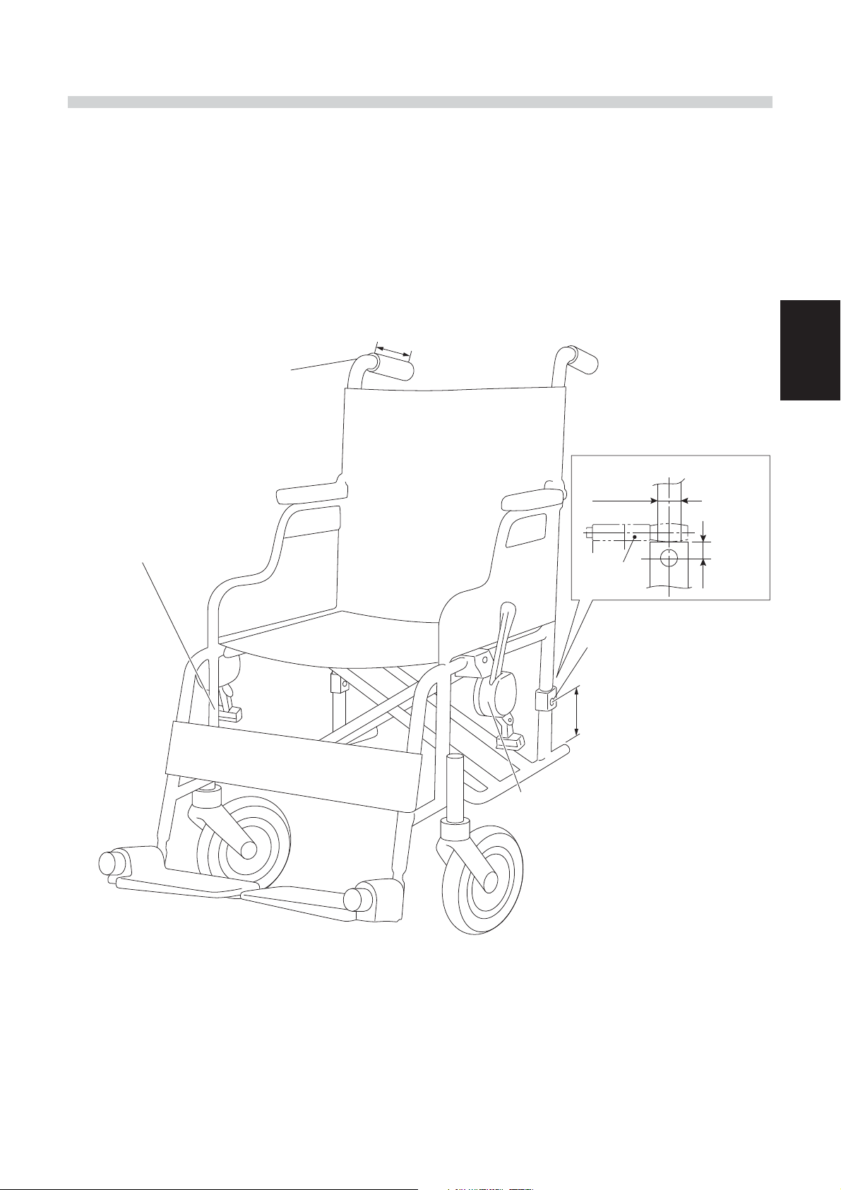
2.2. Structure Conditions
The wheelchair frame must have the following structure.
(1) The diameter of the axle hole is 12.5 to 13.5 mm. (Fixed type case)
(2) The location that the nuts are in contact with around the axle hole must be flat and have
a sufficient surface area. (Fixed type case)
(3) The distance from the center of the axle hole to the base pipe must be at least 70 mm (16"
model bracket A case) or 80 mm (20, 22, 24" model case)
(4) The back pipe diameter must be ø22, and the height of the square lock portion from the
axle hole center must be 20 mm or shorter. (16" model bracket B case)
(5) When attached, the wheelchair frame and the E-Drive must not interfere with each other.
• If installing the adjustment washers in the shaft in order to prevent interference, use up
to 3 per side.
16" Model
[Bracket A] [Bracket B]
7

2
2.3. Functional Conditions
The wheelchair on which the E-Drive PLUS is installed must have the following functions in order to
ensure an appropriate sitting position.
(1) The suitable size of the wheels must be 16, 20, 22 and 24 inches.
(2) Parking brakes must be installed and adjusted to the proper position for the tires. When the E-Drive
PLUS is installed, it must be able to stop the wheelchair at a forward-reverse angle of 7 degrees
when the parking brakes are applied.
(3) When the E-Drive PLUS is installed, a forward-backward tip angle of at least 20 degrees and a side
tip angle of at least 15 degrees must be ensured. (See diagram below) A backward tip angle of at
least 25 degrees is recommended.
(4) Please ensure that the functions of the wheelchair frame are not impaired when the E-Drive PLUS
is installed.
Examples) The movable arm supports can move, the folding feature, reclining feature,
and parking brakes are functional, etc.
2.4. Other
Front casters at least 7 inches in diameter are recommended.
During power driving, operations like caster lifting are not possible. If the casters are small, it is
difficult to get over large bumps. The impact is also greater if the casters are small.
Large diameter (easy to get over bumps) Small diameter (difficult to get over bumps)
8
2.5. Assistant Controller
If installing the optional assistant controller:
(1) The push grip pipe must have a maximum outer diameter of 22 mm.
(2) The push grip pipe must have a minimum inner diameter of 16 mm.
(3) The straight section from the end of the push grip pipe must be 90 mm or longer.
Attaching the assistant controller
Maximum outer pipe diameter 22 mm
Minimum inner pipe diameter 16 mm
Straight section 90 mm or longer
Attaching the controller
Under holder attachment
Pipe diameter ø22, ø19, ø16 mm
Straight section
When using bracket B
ø22 mm
Maximum
20 mm
Bracket B
Wheel hole diameter
ø12.5-13. 5
(Fixed type case)
When using bracket A
At least 70 mm to base pipe
2
When the parking brakes are installed on
E-Drive PLUS models, you can adjust and
move them to the proper position for
16-inch tires.
Front casters with a minimum
size of 7 inches
(recommended)
9

3.
Installation Procedure
3.1. Supplied Parts Check
3.1.1. Supplied Parts Check for 20", 22" and 24" Models
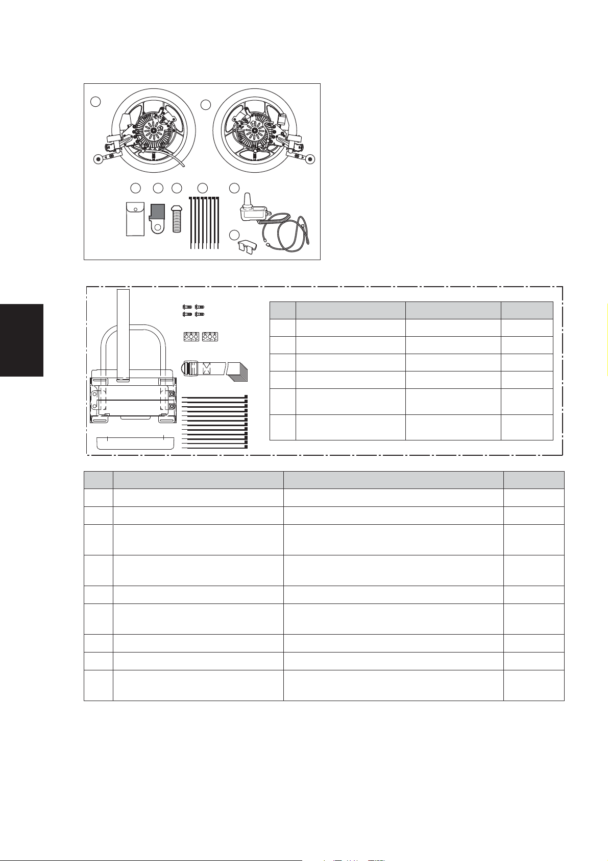
(1) Standard Supplied Parts
3
1
3
4
5
6
Product Name Remarks Quantity
1
Left drive unit assembly 1
2
Right drive unit assembly 1
3
Large clamp For securing the wire harness 2
4
Small clamp For securing the wire harness 2
5
Spiral tube For protecting the wire harness 1
6
Sticker
7
Supplied tools
8
Clamp For securing the wire harness 18
9
Controller assembly 1
:
Plate assembly 1
A
Wheel cap Installed to the drive units 2
2
8
7
10
9
11
For affixing to the manual and power
drive positions
Two 8×10 mm open-end wrenches, and
one 5 mm hexagon wrench
3 each
1
10
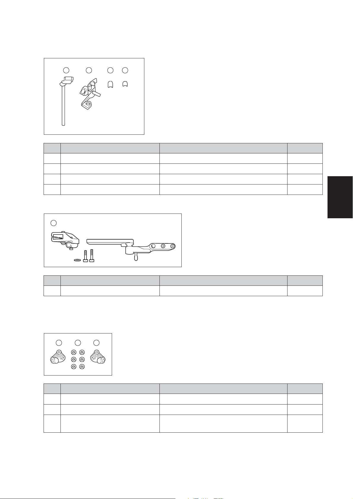
(2) Controller Installation
[Standard]
1 2
Product Name Remarks Quantity
1
Upper holder assembly For installing the controller 1
2
Under holder assembly For installing the controller 1
3
Side plate for ø19–20 For installing the under holder 4
4
Side plate for ø16–17 For installing the under holder 4
[Swing Out Bracket]
1
3 4
3
1
Swing out bracket For installing the controller 1
(3) Battery Location
[No Offset]
1 3 2
1
Left clamp bracket For installing the drive unit 1
2
Right clamp bracket For installing the drive unit 1
3
Plate washer
Product Name Remarks Quantity
Product Name Remarks Quantity
For adjusting the outward position of
the drive unit
6
11

3
[Offset]
Battery Seat Offset Parts (Optional)
28.5 mm Offset
1
32
Product Name Remarks Quantity
1
Spacer 28.5 mm 4
2
Flange bolt 40 mm 1
3
Flange bolt 45 mm 3
4
Left clamp bracket For installing the drive unit 1
5
Right clamp bracket For installing the drive unit 1
6
Plate washer
4 6 5
For adjusting the outward position of
the drive unit
6
12
3.1.2. Supplied Parts Check for 16" Model
(1) Standard Supplied Parts ~Integrated Battery Seat~
1
4 5 6 7
3
Product Name Remarks Quantity
1
Left drive unit assembly 1
2
Right drive unit assembly 1
3
Supplied tools
4
Clamp 1
5
Screw for clamp 1 Used when necessary 1
6
Clamp 2
7
Controller assembly 1
8
Plate assembly 1
2
8
Two 8×10 mm open-end wrenches, and
one 5 mm hexagon wrench
For securing the wire harness to the unit
(used when necessary)
For securing the wire harness to the
wheelchair frame
3
1
1
8
13
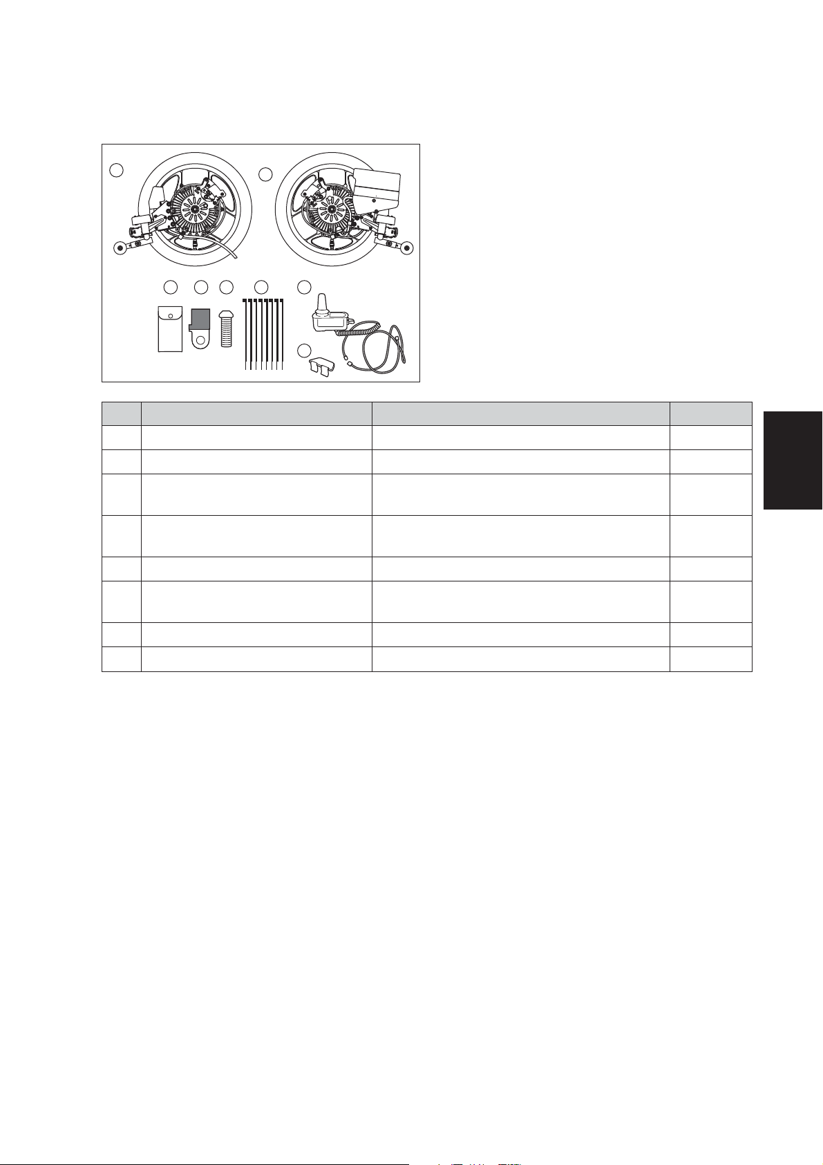
(2) Standard Supplied Parts ~Separate Battery Seat~
3
1
4 5 6 7
3
2
8
:
c.
a.
b.
d.
e.
f.
a.
b.
c.
d.
e.
f.
Product Name Remarks Quantity
Battery box 1
Bottom lid 1
Screw for bottom lid 4
Grommet 2
Band
Clamp
For securing the
battery box
For securing the
wire harness
12
8
Product Name Remarks Quantity
1
Left drive unit assembly 1
2
Right drive unit assembly 1
3
Supplied tools
4
Clamp 1
5
Screw for clamp 1 Used when necessary 1
6
Clamp 2
7
Controller assembly 1
8
Plate assembly 1
9
Battery box assembly
Two 8×10 mm open-end wrenches, and
one 5 mm hexagon wrench
For securing the wire harness to the unit
(used when necessary)
For securing the wire harness to the
wheelchair frame
See the diagram above for the parts
configuration.
1
1
8
1 set
14
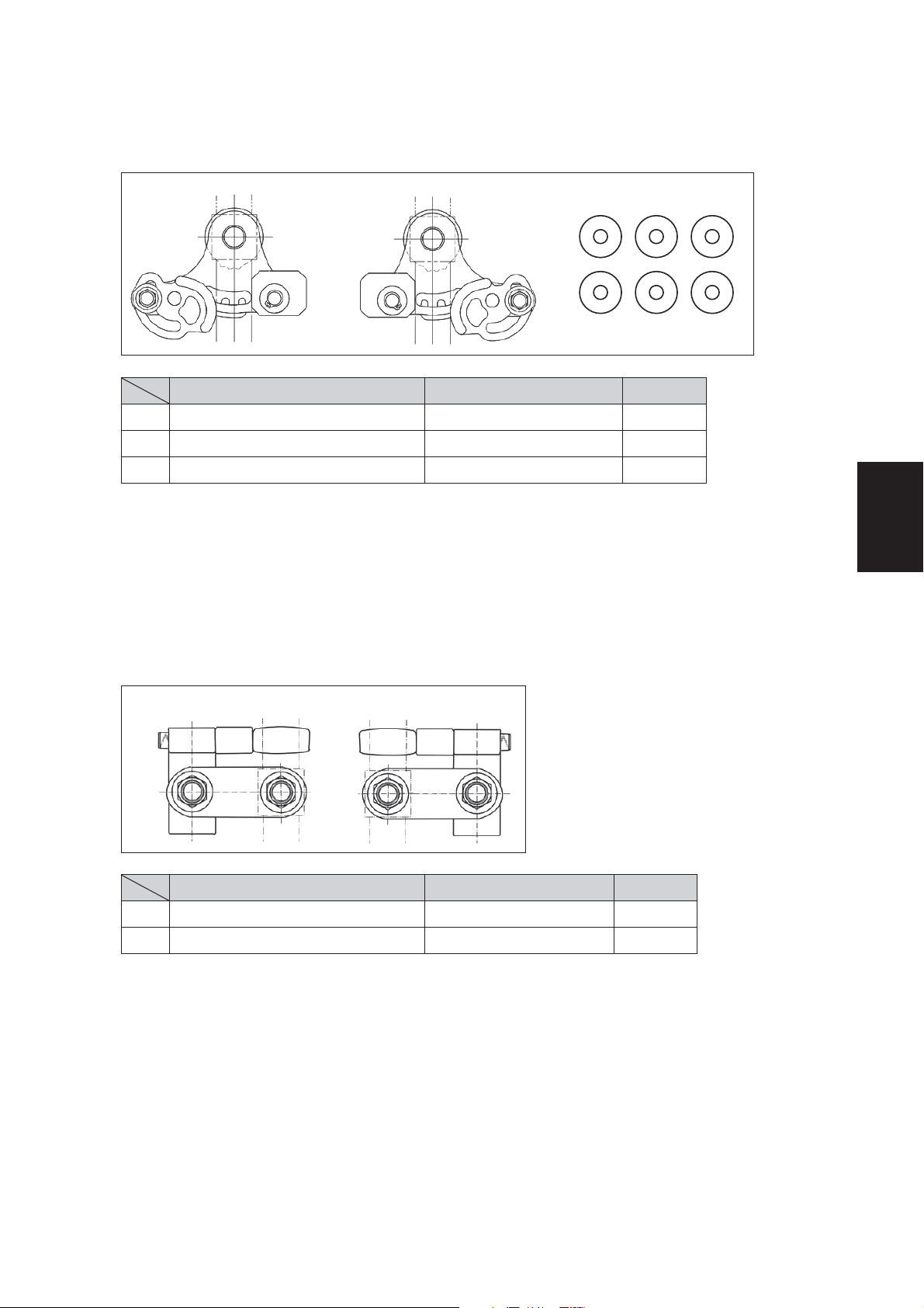
(3) Installation Brackets
1 Bracket A
a. b. c.
Product Name Remarks Quantity
a. Bracket A for left unit 1
b.
Bracket A for right unit 1
c.
Width adjustment washer Used when necessary 6
* Please use a maximum of 3 washers per side.
3
2 Bracket B
a. b.
Product Name Remarks Quantity
a. Bracket B for left unit 1
b.
Bracket B for right unit 1
Use bracket B when the backward tip angle is small.
If bracket B is used, the axles of the E-Drive PLUS can be moved and installed 53.5mm back from
the back pipe of the wheelchair frame.
15
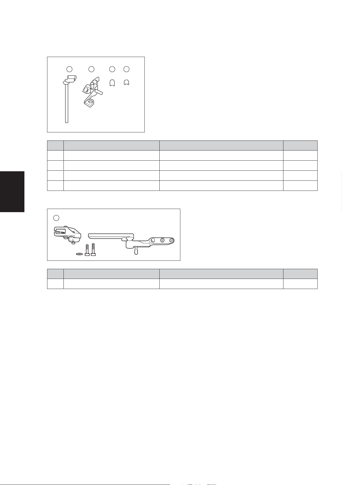
(4) Controller Installation
[Standard]
1 2 3 4
Product Name Remarks Quantity
1
Upper holder assembly For installing the controller 1
2
Under holder assembly For installing the controller 1
3
Side plate for ø19–20 For installing the under holder 4
4
Side plate for ø16–17 For installing the under holder 4
3
[Swing Out Bracket]
1
Product Name Remarks Quantity
1
Swing out bracket For installing the controller 1
16
3.2. Power Unit Installation
NOTICE
When the E-Drive PLUS unit is installed, the unit and the wheelchair frame must not interfere with
each other. When installing the width adjustment washers to the shaft in order to prevent interference, use up to 3 washers per side.
3.2.1. Installation for E-Drive PLUS 20", 22", and 24" Fixed Axle Models
Required tools: 10 mm and 17 mm sockets, socket wrench, and torque
wrench
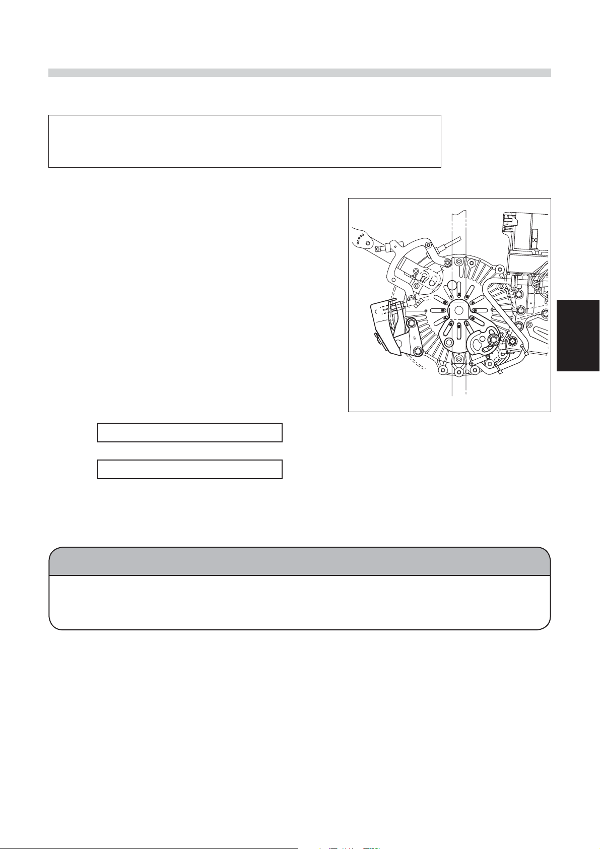
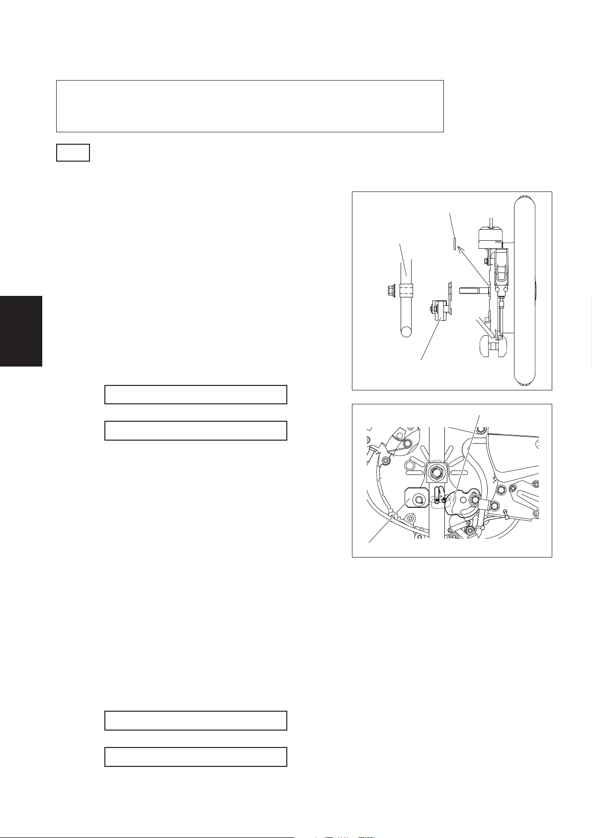
(1) Right Drive Unit Installation
1
Install the clamp bracket for the right unit to
the E-Drive PLUS unit. Fit the projections on
the unit into the slots in the clamp bracket.
(The standard slots are Nos. 6, 7, 8, and 9.)
2
While keeping the clamp bracket and right
unit in this condition, install the unit to the
wheelchair frame. Fit the back pipe of the
wheelchair frame between the post and
stopper of the clamp bracket.
3
Temporarily tighten the axle using the nut
(tightening torque: approximately 5 Nm) so
that there is no looseness in the axle.
4
Move the stopper so that there are no gaps
between the clamp bracket post, frame,
and stopper, and then tighten the stopper
bolt.
3
Tightening torque: 11 to 15 Nm
5
Tighten the axle mounting nut.
Tightening torque: 40 to 50 Nm
(2) Left Drive Unit Installation
Install the left unit in the same way as the right unit.
(3) Angle Adjustment
To adjust the angle 30°, shift the clamp bracket slots by 1 projection on the unit.
17
3.2.2. Installation for E-Drive PLUS 16" Fixed Axle Model (When Using Bracket A)
Required tools: 10 mm and 17 mm sockets, socket wrench, and torque
wrench
3
Note
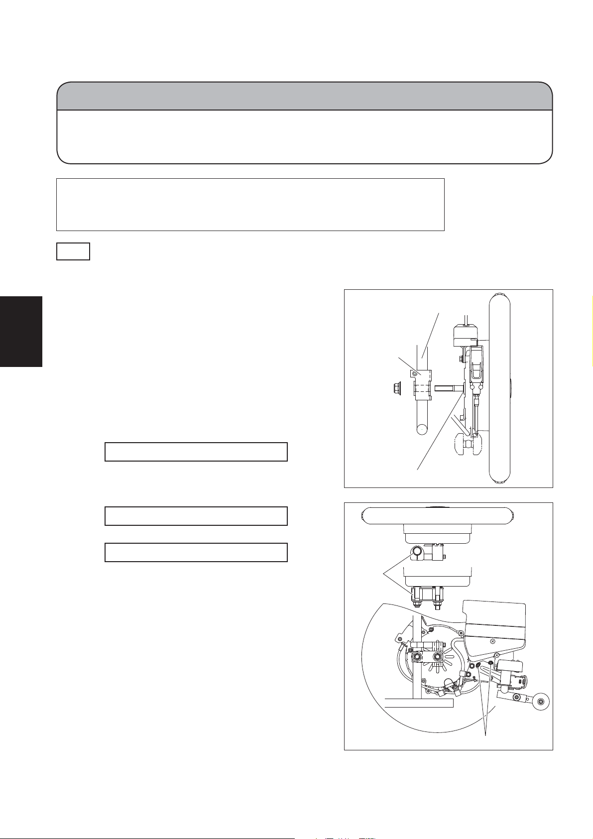
(1) Right Drive Unit Installation
Remove the washers and O rings attached to the axle before installation.
1
Install bracket A for the right unit to the E-
Drive PLUS. Fit the projections on the unit into
the slots in bracket A.
2
While keeping bracket A and the right
unit in this condition, install the unit to the
wheelchair frame. Fit the back pipe of the
wheelchair frame between stopper 1 and
stopper 2 of bracket A.
3
Temporarily tighten the axle using the nut
(tightening torque: approximately 5 Nm) so
that there is no looseness in the axle.
4
Move stopper 1 so that there are no gaps
between the frame, stopper 1, and stopper
2, and then tighten the stopper bolt.
Tightening torque: 9 to 11 Nm
5
Tighten the axle mounting nut.
Tightening torque: 40 to 50 Nm
Remove the washers and O rings
Frame pipe
Bracket A
Stopper 1
(2) Left Drive Unit Installation
1
Install bracket A for the left unit to the E-Drive PLUS. Fit the projections on the unit into the
slots in bracket A.
2
While keeping bracket A and the left unit in this condition, install the unit to the wheel-
chair frame. Fit the back pipe of the wheelchair frame between stopper 1 and stopper
2 of bracket A.
3
Temporarily tighten the axle using the nut (tightening torque: approximately 5 Nm) so
that there is no looseness in the axle.
4
Move stopper 1 so that there are no gaps between the frame, stopper 1, and stopper
2, and then tighten the stopper bolt.
Tightening torque: 9 to 11 Nm
5
Tighten the axle mounting nut.
Tightening torque: 40 to 50 Nm
18
Stopper 2

(3) Angle Adjustment
NOTICE
When the E-Drive PLUS unit is installed, the unit and the wheelchair frame must not interfere with
each other. When installing the width adjustment washers to the shaft in order to prevent interference, use up to 3 washers per side.
1
To adjust the angle 5°, turn stopper 2 on bracket A to change the contact surface of
stopper 2 and the frame.
2
To adjust the angle 15°, shift the bracket A slots by 1 projection on the unit.
3
19
3.2.3. Installation for E-Drive PLUS 16" Fixed Axle Model (When Using Bracket B)
NOTICE
When using bracket B to install the power unit to the wheelchair frame, be sure to
leave the O rings and washers attached to the axle. If the O rings and washers are
removed, the power unit will be damaged.
Required tools: 17 mm socket, socket wrench, torque wrench, 17×19
mm open-end wrench, and 5 mm hexagon wrench
3
Note
(1) Right Drive Unit Installation
Leave the washers and O rings attached to the axle during installation.
1
Temporarily tighten bracket B for the right
unit to the back pipe using the frame axle
hole. Align the holes in the plate and boss
and tighten sufficiently to remove any
looseness.
2
Temporarily tighten the drive unit using the
mounting nut. The nut is temporarily tightened to prevent the drive unit from falling;
therefore, do not tighten the nut forcefully.
3
Fully tighten the nut that was temporarily
tightened to the frame axle hole.
Tightening torque: 40 to 50 Nm
4
Fit the projections on the back of the drive
unit into the slots in bracket B, and then
fully tighten the axle.
Tightening torque: 40 to 50 Nm
5
Fully tighten the bolt.
Frame pipe
Bracket B
Washer and O ring
Tightening torque: 14 to 16 Nm
Frame
pipe
20
Adjusting holes

(2) Left Drive Unit Installation
1
Temporarily tighten bracket B for the left unit to the back pipe using the frame axle
hole. Align the holes in the plate and boss and tighten sufficiently to remove any
looseness.
2
Temporarily tighten the drive unit using the mounting nut. The nut is temporarily tight-
ened to prevent the drive unit from falling; therefore, do not tighten the nut forcefully.
3
Fully tighten the nut that was temporarily tightened to the frame axle hole.
Tightening torque: 40 to 50 Nm
4
Fit the projections on the back of the drive unit into the slots in bracket B, and then
fully tighten the axle.
Tightening torque: 40 to 50 Nm
5
Fully tighten the bolt.
Tightening torque: 14 to 16 Nm
(3) Angle Adjustment
To adjust the angle 30°, shift the clamp bracket slots by 1 projection on the unit.
3
21
3
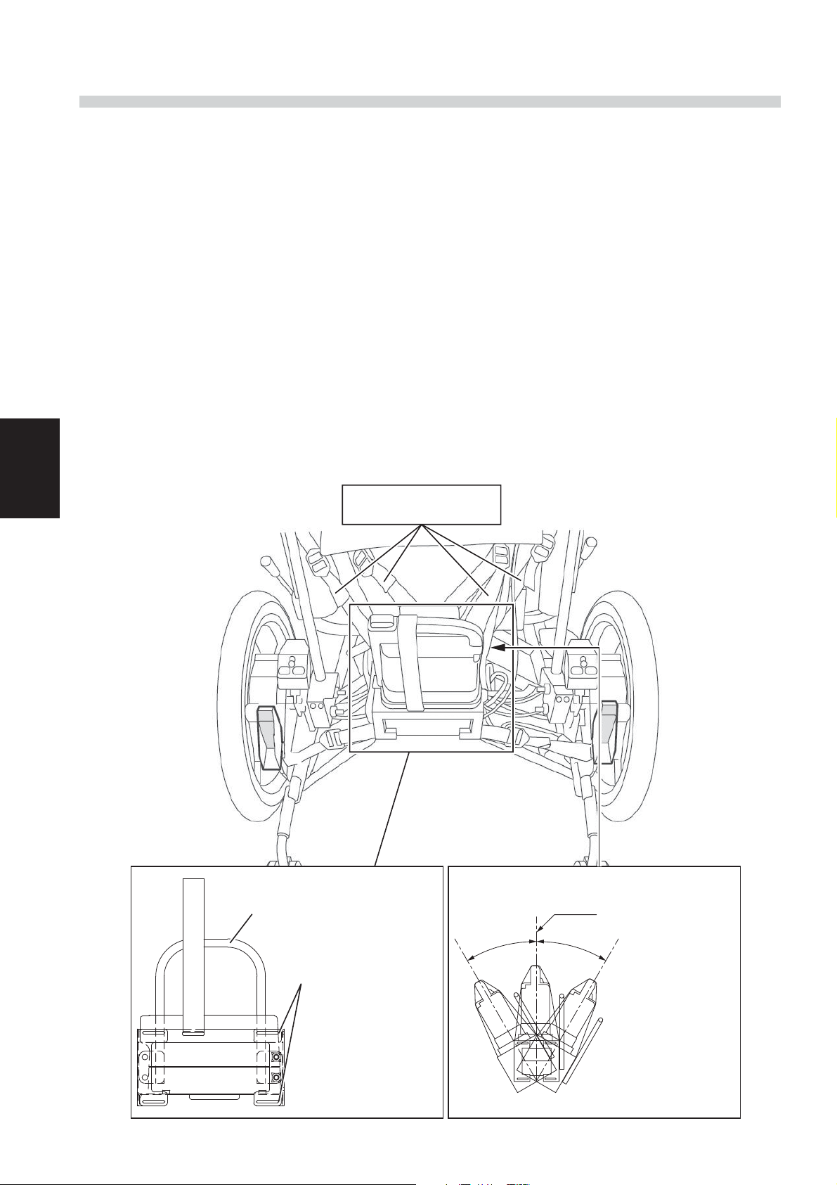
3.3. Separate Battery Seat Installation
If using the separate battery seat, secure the battery box to the wheelchair frame.
(1) Pass the belts through the elongated holes on the battery box.
(A total of 8 belts are used.)
(2) Secure the battery box to the wheelchair frame.
Please secure the battery box so that the U bracket goes backwards.
After the belts are passed through the elongated holes and U bracket of the battery box,
pass them through parts of the frame, such as the seat and back pipe.
(A total of 8 belts are used.)
Position the battery box with the 4 belts on top, then add tension and secure it with the 4
on the bottom.
(3) After the battery is installed, ensure that it is firmly secured. If the ends of the belts hang
down, ensure that they do not interfere with the turning and moving parts of the wheelchair
frame.
Use all of the belts
(8 in total).
22
U bracket
There are elongated
holes that the belts
pass through on the
top and bottom of
the battery box
frame.
Align them with the
wheelchair frame.
Vertical
Maximum 30° Maximum 30°
Ensure that the
battery box is
installed at an angle
of no more than 30°
from vertical.
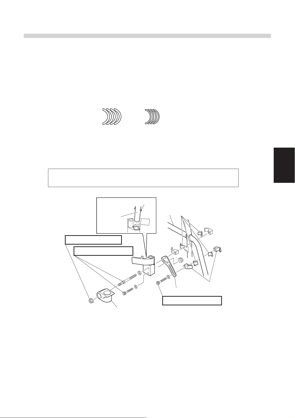
3.4. Controller Installation
(1) Under Holder Assembly Installation
Install the under holder onto the wheelchair frame.
1
From the temporarily-assembled under holder assembly, remove the under holder
piece.
2
Mount the assembly onto the wheelchair frame. If necessary, insert the side plates
between the brackets and the wheelchair frame.
For Ǿ16
<Side plates (included)>
3
Attach the under holder piece.
Required tools: 10 mm socket, socket wrench, torque wrench
8×10 mm open-end wrench, 5 mm hexagon wrench
Anti-swivel pin
Upper
holder
For Ǿ19
Wheelchair
frame
Tightening torque: 5 to 8 Nm
Tightening torque: 14 to 16 Nm
3
Side plates
Brackets
Plate stopper
Tightening torque: 14 to 16 Nm
Under holder
* The illustration above is for the right-hand drive model. For the left-hand drive
model, the placement of the parts will be the opposite of the above illustration.
Insert it so that the anti-swivel
pin faces forward, and secure
it with the bolt.
23
3
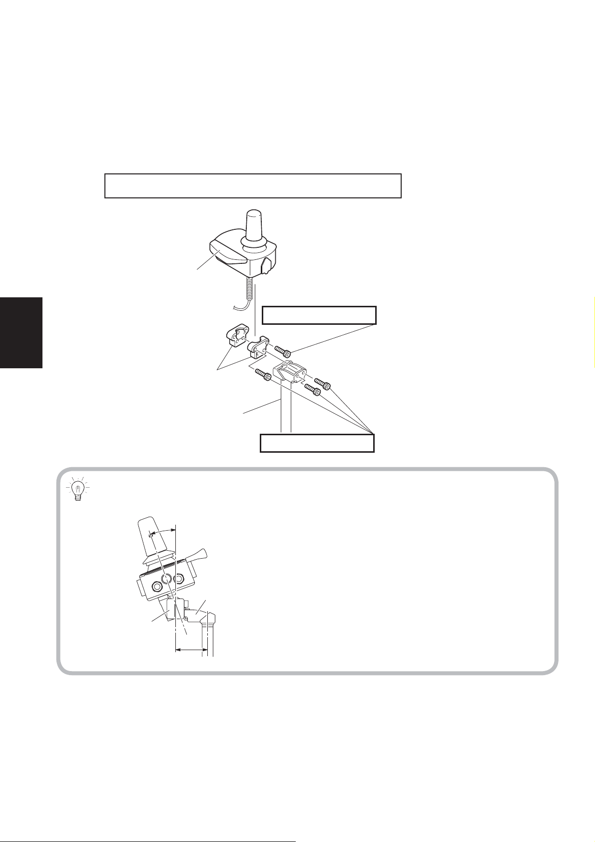
(2) Upper Holder Assembly and Controller Installation
Install the upper holder onto the controller and adjust the position.
1
Remove the bracket from the upper holder and install it onto the controller.
2
Install the bracket onto the upper holder.
Required tools: 5 mm hexagon wrench, torque wrench
Hand rest plate
Tightening torque: 6 to 8 Nm
Brackets
Upper holder assembly
Tightening torque: 6 to 8 Nm
Adjusting the Installation Position of the Controller (Part 1)
20°
Holder
Bracket
48 mm
• The brackets can be installed on the outside
of the holder.
• The angle of the controller can be changed
within a 20-degree span.
24
3
WARNING
Removal of the Controller
For example, when the customer wants to sit close to a table, the controller can be
detached with moving the under holder locking lever.
Do not remove the controller from the under holder while the power is switched ON.
Once you remove the controller from the under holder, do not switch the power ON.
The control lever may tilt to cause the wheelchair to move unexpectedly, and you
or other people around you may get injured.
In addition, if you removed the retaining bolt, you can use the supplied hand-tight-
ened screw.
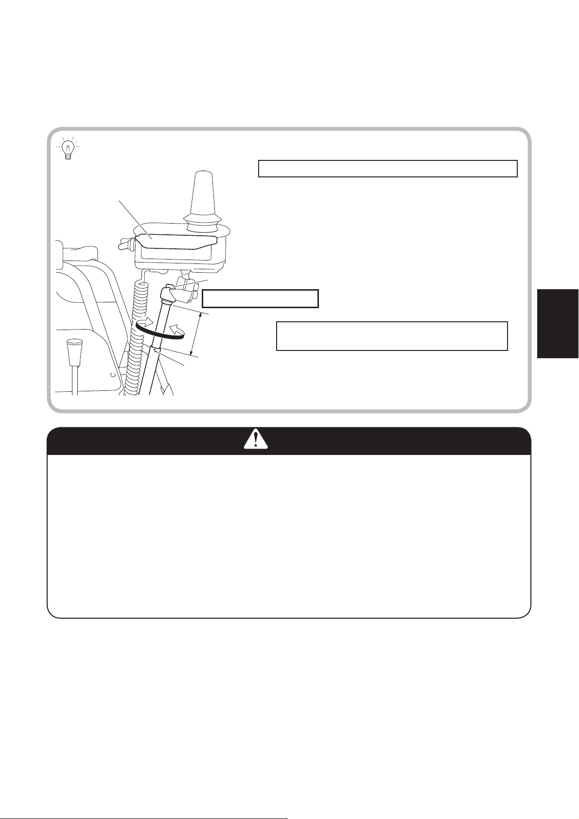
Adjust the installation position.
Adjust the controller to a position that is easiest to operate by taking the height,
angle, and its distance to the arm support into consideration.
Adjusting the Installation Position of the Controller (Part 2)
Required tools: 5 mm hexagon wrench
Hand rest plate
• Adjust the height so that the punch mark (adjustment limit punch mark) remains hidden.
Height-adjusting bolt
Tightening torque: 14 to 16 Nm
Maximum 60 mm
Punch mark
Switching the hand rest plate to the left- or
right-hand side
On the left-hand drive model, remove the hand
rest plate by pulling it upward, change the rubber plate direction and relocate it to the left.
3
25

3
(3) Swing Out Bracket
1
Fit bar 1 into the pipe. Make sure that bar 1
is installed in the correct direction.
Install the holder, and then tighten the bolt.
Front (25 mm)
Tightening torque: 6 to 8 Nm
Rear (40 mm or 45 mm)
Tightening torque: 2 to 3 Nm
2
Install the upper holder assembly to the
holder and temporarily tighten it.
3
Install the upper holder assembly to the
controller and temporarily tighten it.
26
(4) Wire Routing
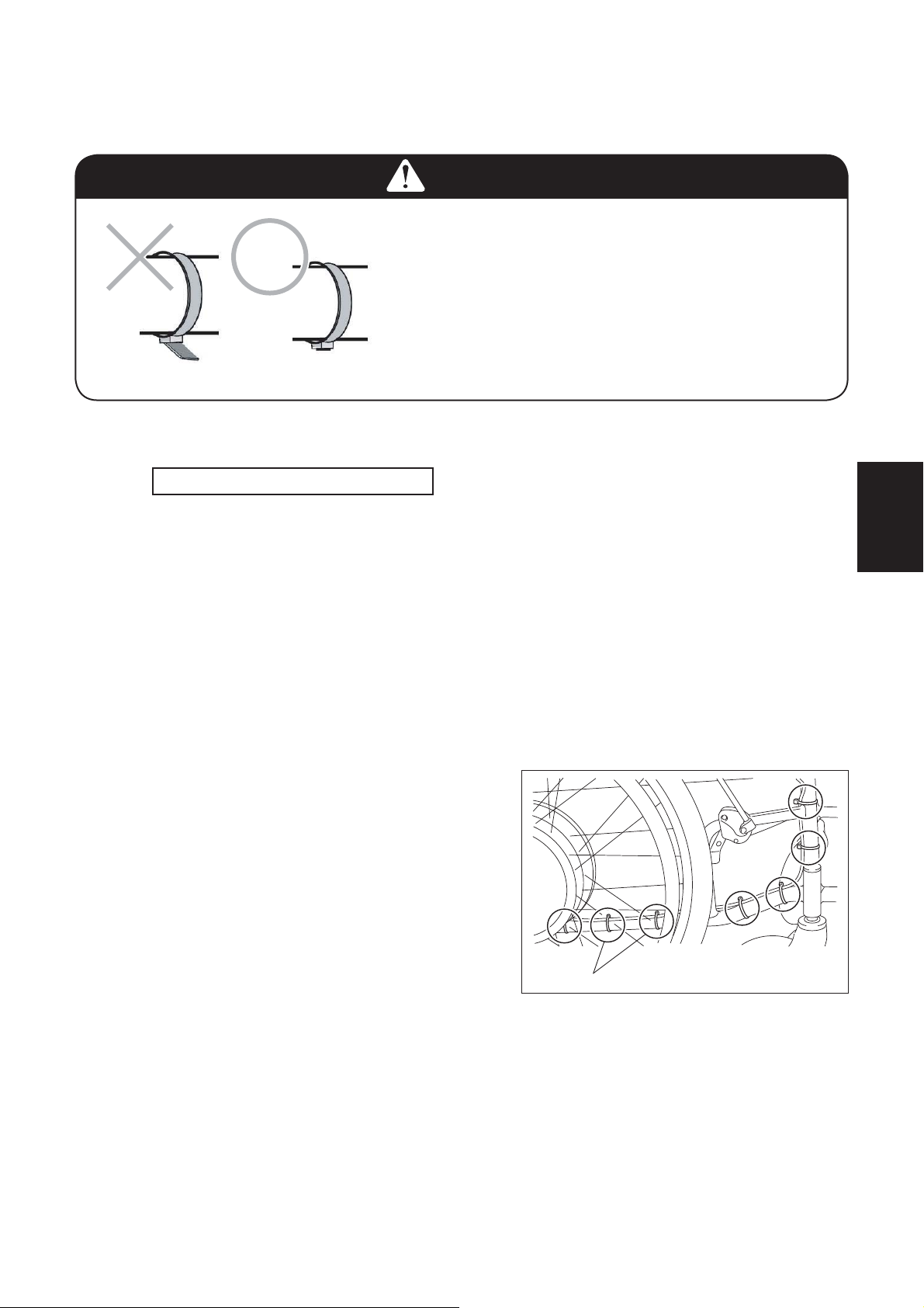
WARNING
Route and secure the wires correctly not to
entwine or touch to the unit rotating parts,
even the unit is detachable one and when the
wire connectors are disconnected.
When cutting off excess tie strap, do not cut
diagonally, and cut as close to the knot as
possible. If you leave the straps with sharp
ends, the customer may get injured.
Route the controller lead wire and the left unit harness, and connect to the power unit.
1
Route the lead wires for the controller/assistant controller and the left unit harness.
Required tools: Wire cutters
Route the wires in such a way to meet the following requirements.
• Run the wire along the top and inner sides of the pipe, secure it with tie straps.
• Fasten the tie straps in 5 to 10 cm intervals.
• Make sure the wire does not interfere with the rear tire.
• Make sure the wire does not interfere with or get caught between moving parts
like the anti-tip bars of the wheelchair frame.
* Pay special attention when tilting or reclining.
• When folding up the wheelchair, make sure the wire does not get caught by the
crossbar.
• Fasten the tie straps loosely at the junction between the crossbar and the pipe,
so that the lead wire does not get twisted.
• In case the unit is detachable one,
make sure to secure the wires to make
appropriate margin length for the connecting/disconnecting.
• Use single edged nippers to cut the
ends of the tie straps.
• In case the separated battery seat
type unit, make sure not to connect
the left/right wires in reverse.
Example of wire routing
3
2
Remove the cover under the battery seat.
27
3
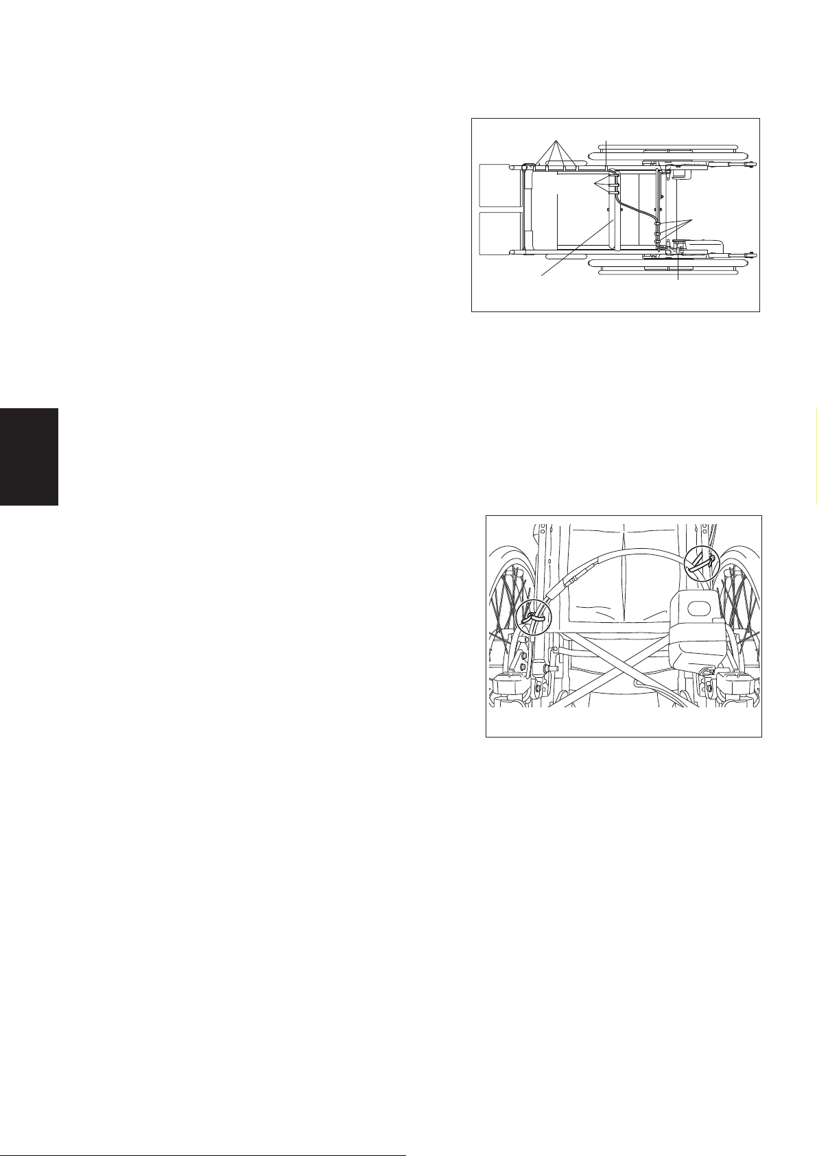
(5) Wire Routing for Left-Side Installation of Control-
ler
1
With the controller installed on the left side
of the wheelchair, route the lead wires from
below the under holder toward the battery
seat. Route the lead wires along the frame
and crossbars, securing the lead wires at 5
to 10 cm intervals. (See diagram at right.)
2
When routing the lead wires along the base
pipe, route them on top of the pipe and
secure them.
3
When routing the lead wires along the
crossbars, route the leads so that they will
not be pinched by the pipes, be pulled, or
become twisted or slack when the wheelchair is folded.
4
Use wire cutters or a similar tool to cut
off the excess ends of clamps so that the
ends do not protrude.
5
Connect the control unit according to the
instructions in “(8) Connecting the Control
Unit and Lead Wires” in 3.4.
Tie straps Tie straps
Tie straps
Crossbars
(Bottom view)
Tie straps
Tie straps
(6) Wire Harness Routing for the Left Drive Unit
(20", 22", and 24" Models)
1
Route the wire harness so that it forms
an upward arch and adjust the length of
the harness so that it will not be pulled
or become too slack. (If the wire harness
is hanging down, it can easily become
caught, causing a malfunction.)
2
Adjust the position of the arched portion of
the wire harness so that any items will not
rest on top of the wire harness. If necessary, use the 2 large clamps and 2 small
clamps that are supplied to secure the wire
harness.
(Fixed Axle Model Sample)
28
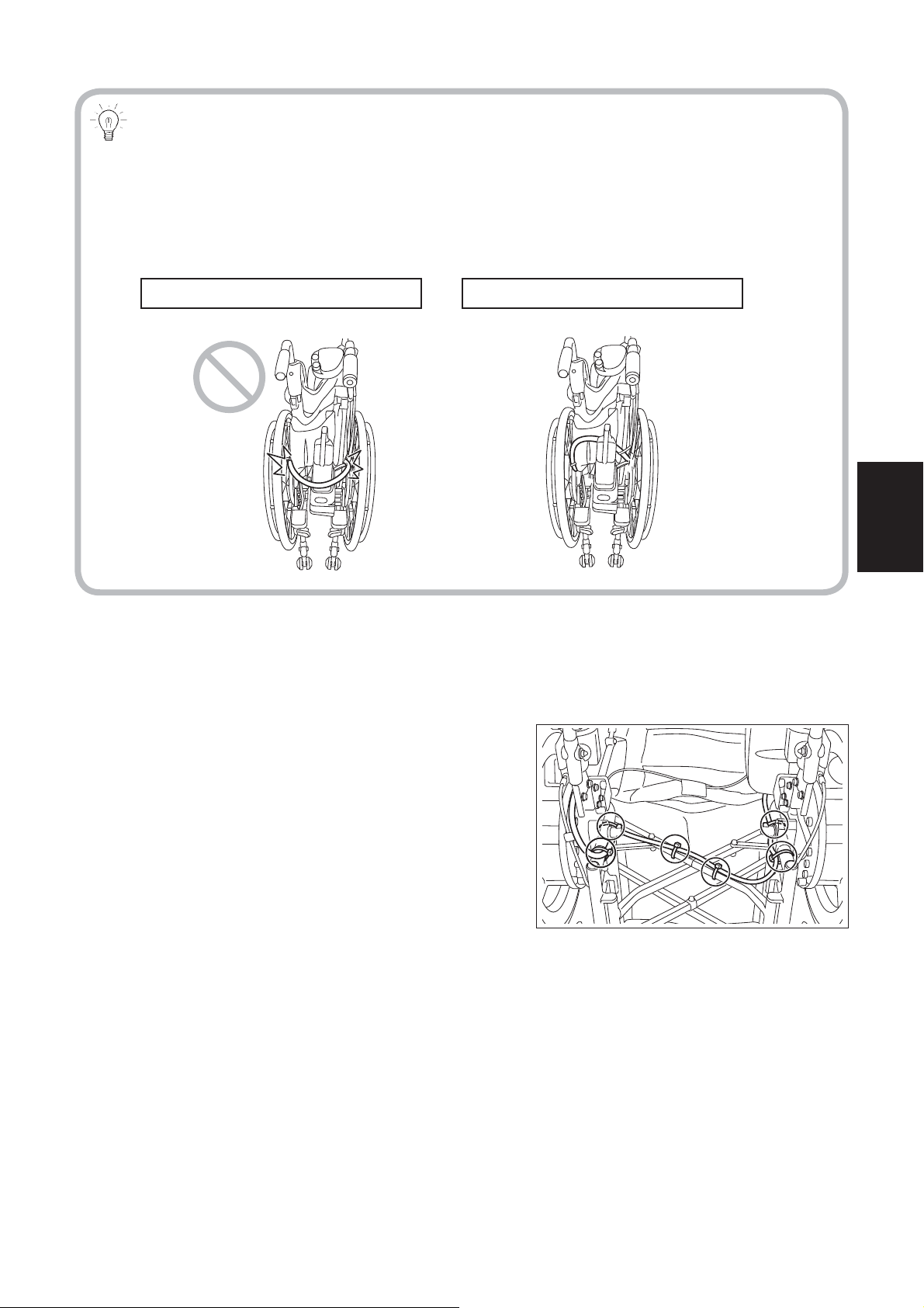
Secure the wire harness if necessary.
If the wire harness behind the seat back is not secured, the battery may be positioned to the inside of the harness as shown in the “×” diagram (lower left) when the
wheelchair is folded.
If the wheelchair is unfolded in this condition, an excessive force will be applied to
the wire harness and the wire harness could be damaged.
When not secured
3
Connect the control unit according to the instructions in “(8) Connecting the Control
Unit and Lead Wires” in 3.4.
(7) Wire Harness Routing for the Left Drive Unit (16"
Model)
1
Route the wire harness along the frame
and temporarily secure it using clamps.
2
Adjust the wire harness so that it will not
be pulled or become too slack.
3
Check that the wire harness is not pulled
when the frame is folded.
4
Use single edged nippers or a similar tool
to cut off the excess ends of clamps so
that the ends do not protrude.
5
Connect the control unit according to the
instructions in “(8) Connecting the Control
Unit and Lead Wires” in 3.4.
When secured
3
29
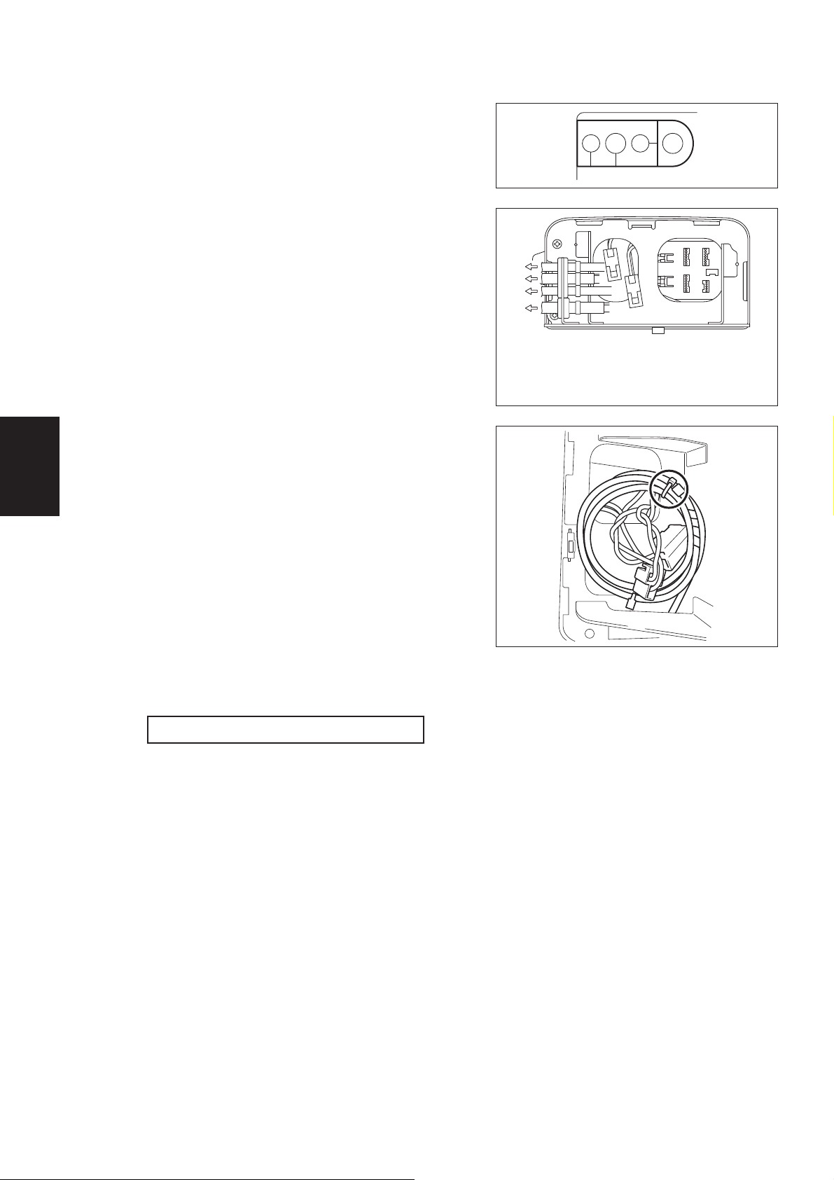
(8) Connecting the Control Unit and Lead Wires
1
Remove the cover under the battery seat.
2
Route the lead wires and wire harness
through the grommet.
Inner 1: Controller lead wire
Center L: Left unit wire harness
Outer 2: Assistant controller lead wire
2L1
3
3
Connect the connectors to the control unit
assembly. The connectors can be connect-
ed to any receptacle as long as the shapes
match.
4
Coil the excess lead wires and left unit wire
harness, and bind them with a clamp.
5
Install the plate cover. Make sure not to
pinch the lead wires and wire harness
when installing the cover.
a.
b.
c.
d.
a. To the assistant controller
b. To the left motor control
c. To the controller
d. To the right motor control
Tightening torque: 1.5 to 2.5 Nm
30
 Loading...