

DECODE PRM4 User Manual

DECODE
Radio modem PRM4 868MHz
User's manual v1.6
http://www.decode.rs

Table of Contents
1 Introduction...............................................................................................................4
2 Modes of operation....................................................................................................5
3 Installing the device...................................................................................................8
3.1 Power supply..................................................................................................8
3.2 Serial connector..............................................................................................8
3.3 The antenna connector.................................................................................10
3.4 Signaling lights............................................................................................10
3.5 Jumpers........................................................................................................11
4 AT command set......................................................................................................12
4.1 Setup of the serial interface parameters.......................................................14
4.2 Setup of the radio interface..........................................................................15
4.3 Command mode setup..................................................................................16
4.4 Reduced power consumption mode setup....................................................16
5 Firmware update.....................................................................................................18
5.1 The procedure for writing the new firmware...............................................18
6 Technical specifications..........................................................................................19
Radio modem PRM4 868MHz /User's manual V1.6 / 24.05.2011 2

Document history
Date 29.04.2009 Initial version of the documentv1.0
Date 23.06.2009 Revision v1.1
Date 09.12.2009 Revision v1.4 Added AT commands EC and ET. Corrected the
AM command format.
Date 08.02.2010 Revision v1.5 Bug related to incomplete flushing of transmit
buffer when sending data by full-buffer criteria, corrected.
Corrected bug related to saving of parameters which haven't
been saved with ATWR command while exiting command
mode. New function introduced to keep the same bps and data
format while entering command mode with +++ sequence.
New function that set speed to 9600 bps and data format to 8N1
while entering command mode with SET pushbutton. Bug
related to same speed 9600 bps while entering command mode
with SET pushbutton, corrected.
Date 24.05.2011 New parameter ReceiverThreshold added for setting of receive
level in Sleep mode and averaging RSSI values for arbitration
of receiver wakeup.
1 Introduction
Decode PRM4 modem is used for data transmission in UHF ISM 868MHz band.
Through the use of radio interface it procures networking of devices and systems.
Easy to use, the PRM 4 provides secure method of connecting computers, PLC
devices, measuring devices and SCADA systems.
The device transports the asynchronous serial data between two or more PRM4
devices in point-to-point or point-to-multipoint configuration. The RS-232/485/422
connection enables the implementation of the device into the existing systems without
the need for additional equipment.
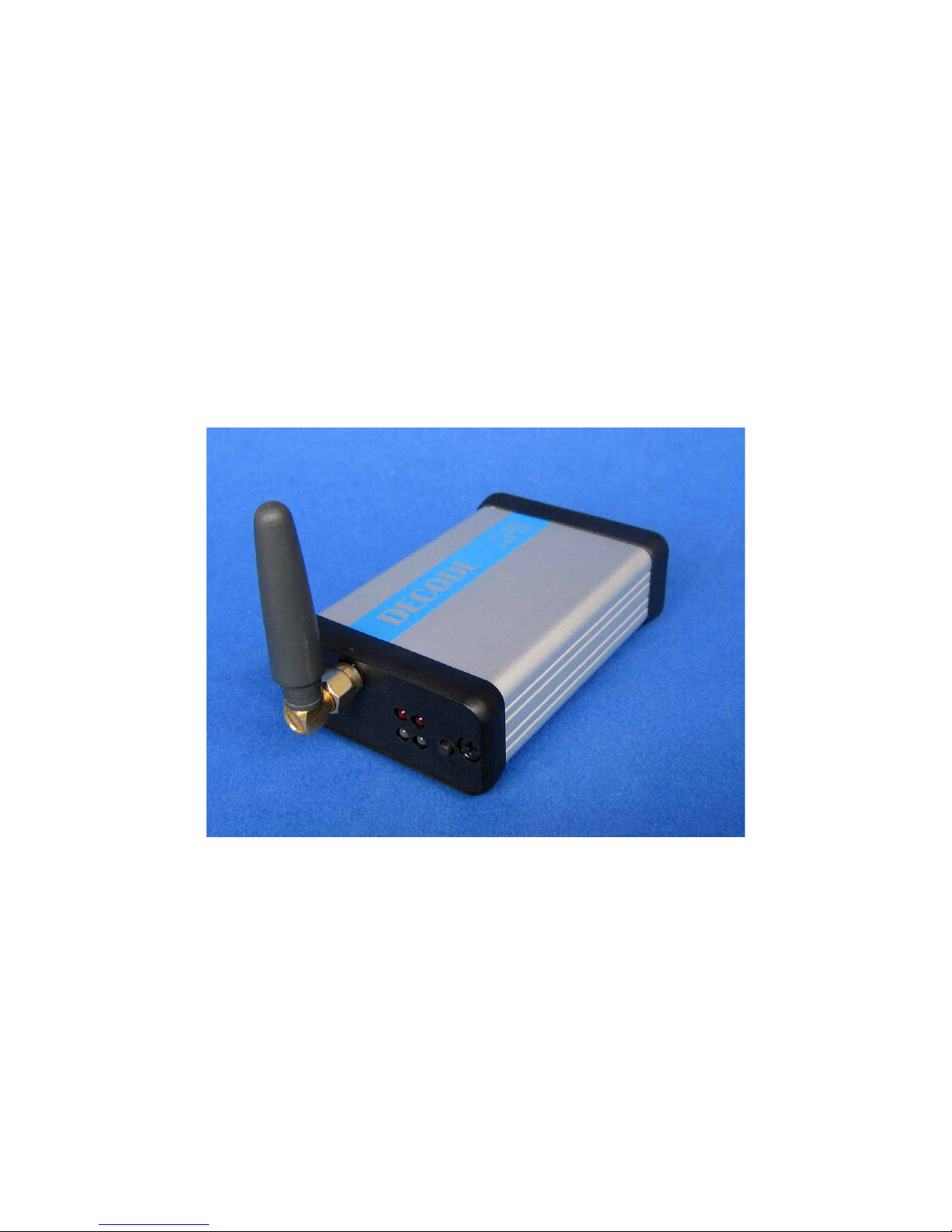
PRM4 Device
The standard delivery contains the PRM4 device, network power supply adapter for
230V, mini omni-directional antenna for ISM 868MHz band, DB9 M-F serial cable
and CD with this manual and necessary software.
Radio modem PRM4 868MHz /User's manual V1.6 / 24.05.2011 4

2 Modes of operation
Decode PRM4 device can operate in one of the two modes of operation.
When powered, the device will automatically enter the default, data transfer mode.
When the device is in the data transfer mode, it will listen and receive all the packets
intended for it, whereas the transmitter will turn-on only occasionally to send the data
acquired from the wire connection.
The mode and parameters of operation are set through the use of AT commands using
the command mode of operation. The transfer into the command mode and the set of
supported AT commands is described in chapter 4.
The PRM 4 device supports an addressing scheme. All modems intended for data
exchange in a radio network must be set to the same frequency and must have the
same network address (NA). The NA can be set to any value from the 0 – 65535
range. Each device has its source address (SA) used to identify the device inside a
network. The SA can take values between 0 and 255 inclusive. Note that the SA must
be set uniquely inside a network. If a point-to-multipoint connection is required (e.g.
for master-slave protocols used with SCADA software or PLC devices) the
destination address (DA) masking is used. This way it is possible to mask a number
of bits when comparing the DA and SA and, consequently, the packet with one
destination address can be sent to multiple devices having the unmasked parts of their
SA match the unmasked parts of DA.
For example, if assumed that the radio frequency and the NA are the same for all the
devices in the following figure, the device with the SA equal to 100 will send its
packets to the remaining three devices, whereas the devices with the SA 1,2 and 3 will
send data only to the SA 100 device. This is because the Address Masks (AM) on
devices with SA 1,2 and 3 have been set to 252 (binary 11111100) so that they match
the higher (unmasked) six bits of the DA (binary 000000).
Radio modem PRM4 868MHz /User's manual V1.6 / 24.05.2011 5
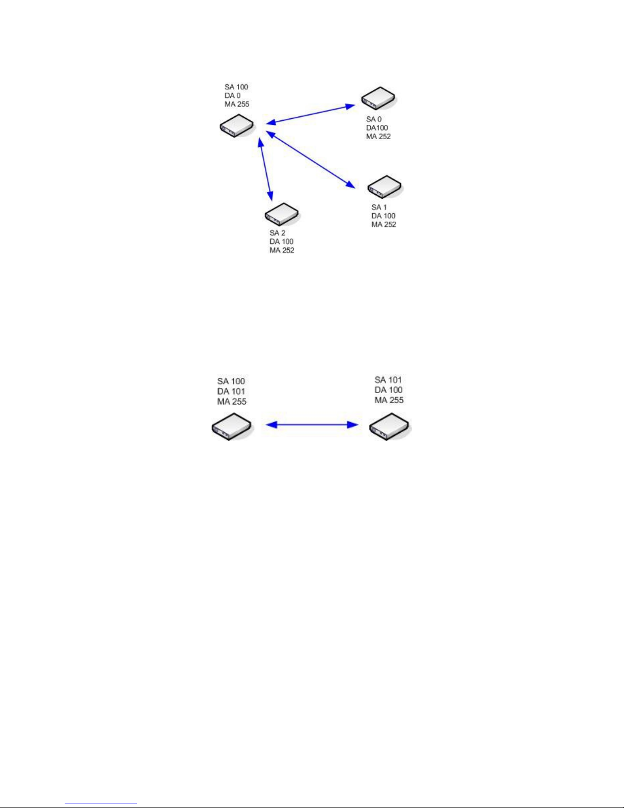
Point-to-multipoint connection
The below figure illustrates the point-to-point connection. The AM is set to 255 so all
the bits are compared and only the exact match of the SA and DA would lead to
receipt of the packets. The NAs as well as the radio frequencies are set as with the
previous example.
Point-to-point connection
The PRM 4 device receives over the serial interface and buffers the data that needs to
be sent until the condition for sending the data is met. The data is sent when there are
no new data for a specified time interval after the last data has been received on the
serial interface. This time interval can be set by using the AT commands and it is
referred to as the packetization timeout. The default value of this parameter is set to
5ms. In other words, if communicating on 9600bps, a 5 character pause will induce
the modem to send the entire memory content within one packet. The transmit data
buffer size is 512 bytes.
The following figure shows the example of three-character packet generation and
sending on 9600bps with default packetization timeout.
Radio modem PRM4 868MHz /User's manual V1.6 / 24.05.2011 6
 Loading...