

DECODE GT340 User Manual

User's Manual
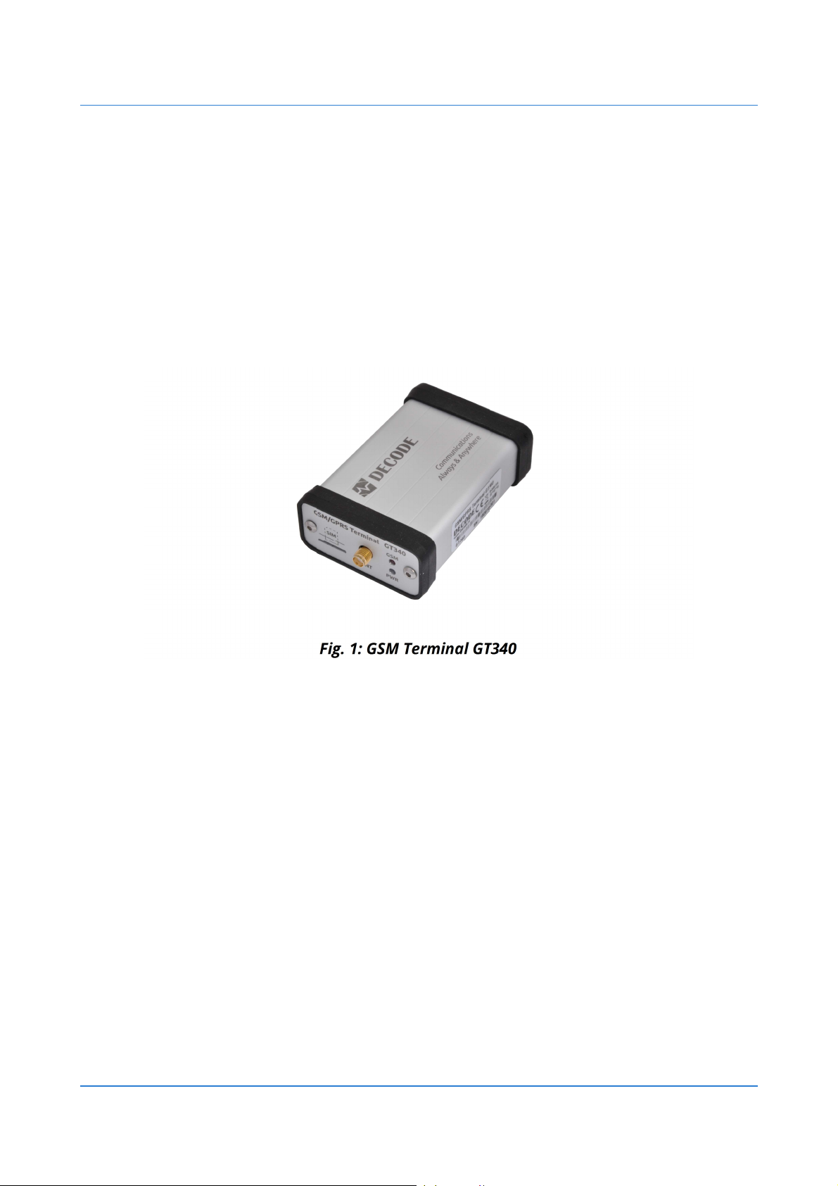
GSM Terminal GT340
Industrial GSM Communicator

Legal notice
Reproduction, transfer, distribution or storage of part or all of the contents in this document
in any form without the prior written permission is prohibited. All rights reserved. All
trademarks mentioned herein belong to their respective owners.
Copyright © 2018 Decode
Disclaimer
Decode has used reasonable care in preparing the information included in this document, but
does not warrant that such information is error free.
Decode, its associates, representatives, employees, and others acting on its behalf disclaim
any and all liability for errors, inaccuracies, or incompleteness contained in any datasheet or
in any other disclosure relating to any product.
In the interest of continuous product development, the Decode reserves the right to make
improvements to this manual and the products described in it at any time and without prior
notification or obligation.
The use of the product is at sole discretion of the user. Decode cannot be held responsible for
any damages arising due to use of this product and makes no warranty, representation or
guarantee regarding the suitability of the products for any particular purpose or the
continuing production of any product.
Note: The specifications in this document are valid as of the listed versions of software and/or
hardware. Revised versions of this manual, as well as software and driver updates are
available in the download area of the Decode web site.

Table of Contents
1 Preface......................................................................................................................4
1.1 Symbols.......................................................................................................................................4
1.2 Safety Instructions......................................................................................................................4
1.3 Document versions....................................................................................................................5
2 Overview..................................................................................................................6
2.1 Ordering information.................................................................................................................7
2.2 Accessories..................................................................................................................................7
3 Device Description...................................................................................................8
3.1 SIM card.......................................................................................................................................8
3.2 Antenna connection...................................................................................................................9
3.3 LED indicators...........................................................................................................................10
3.4 RS232 serial interface..............................................................................................................11
3.5 Power supply............................................................................................................................12
3.6 DIN rail mounting holder........................................................................................................12
4 Operation description...........................................................................................13
4.1 Basic operation.........................................................................................................................13
4.1.1 Terminal program............................................................................................................13
4.1.2 AT command guide..........................................................................................................14
4.1.3 Factory settings................................................................................................................15
4.2 Dial-up connection...................................................................................................................16
4.2.1 Modem driver Installation..............................................................................................16
4.2.2 Creating Dial-up connection...........................................................................................21
5 Technical specifications........................................................................................23
6 Troubleshooting.....................................................................................................25
6.1 The PWR LED does not light....................................................................................................25
6.2 The GSM LED does not light...................................................................................................25
6.3 The terminal does not respond.............................................................................................25
7 Product label..........................................................................................................26
8 Disposal and Recycling..........................................................................................26
9 Contact...................................................................................................................26
User's Manual GSM Terminal GT340 Preface
www.decode.rs4/26
1 Preface
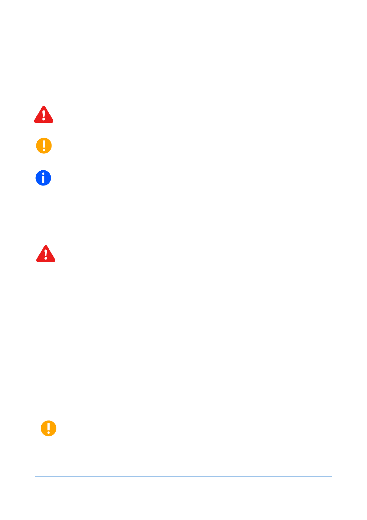
1.1 Symbols
WARNING - Safety notice, which must be followed, may have influence on the user’s
safety or the function of the device.
IMPORTANT - Notice, which must be followed to avoid possible problems, which can
arise in specific cases.
NOTE - Notice, which contains useful advice.
1.2 Safety Instructions
Device must be used in compliance with any and all applicable international and national laws
and in compliance with special restrictions regulating the utilization of the communications of
the communication module in prescribed applications and environments.
WARNING - We suggest you to adhere to following recommendations so as to
avoid any damage to person or property.
• All the associated (interconnected) equipment, PC and power supply units (PSU)
shell comply with requirements of standard IEC 60950- 1:2005+A1:2009+A2:2013.
• Power supply must have SELV output and for security reasons connection must
include series 1A fuse protection.
• Access to relay connections must be checked and restricted in the end
installation using potential hazardous voltage.
• Installation and technical support of the device can be performed only by a
qualified personnel or a person who has enough knowledge about this device
and safety requirements.
• Unauthorized modifications or utilization of accessories that have not been
approved may result in damage to the device and in a breach of applicable
regulations, and result in the termination of the validity of the guarantee.
• Do not expose the device to extreme ambient conditions. Protect the device
against dust, moisture and high temperature.
IMPORTANT - GSM radio signal level and availability depends on the environment in
which it is working, which could affect performance and functioning of device.

User's Manual GSM Terminal GT340 Preface
www.decode.rs5/26
1.3 Document versions
Document
version
v1.0 24/07/2018 First release
Date Note
User's Manual GSM Terminal GT340 Overview
www.decode.rs6/26
2 Overview
DECODE GT340 is compact dual-band GSM/GPRS terminal which enables easy connection of
the user devices and PCs to the GSM network. It is based on uBlox SARA-G340 module with
integrated TCP/IP stack. The micro SIM card is placed through the hole on the front panel of
the device. Communication connector is standard DB9 female connector with RS232 DCE
interface. The antenna connects to the female SMA 50Ω connector. LEDs on the front panel
indicate the presence of the power supply voltage and activity of the GSM network. The device
is powered by DC voltage in the range of 8V to 30V. Device is delivered in desktop case, but by
adding an optional adapter, it can be mounted on DIN 35mm rail.
DECODE GT900 terminal enables the communication of electronic devices and systems over
GSM network using GPRS, CSD and SMS services. It is specially designed for remote
monitoring and control of industrial processes, security systems, POS terminals, level readers
(gas, water, electricity...).
Typical applications include:
• remote PLCs reading and control
• remote process monitoring
• paying at POS (point-of-sale) terminals
• vending machine monitoring
• traffic management
• device service and maintenance
• alarm systems
User's Manual GSM Terminal GT340 Overview
www.decode.rs7/26
2.1 Ordering information
Package include GSM Terminal GT340 in desktop aluminum case. For additional equipment
see section 2.2 Accessories.
Model SKU Description
GT340 10410
GSM/GPRS terminal, 900 MHz/1900 MHz, desktop case,
RS-232 DCE interface, power supply voltage 8 - 30 V DC
2.2 Accessories
Additional equipment is listed in the table below. More information about accessories can be
found in the next chapter or at www.decode.rs.
Model SKU Description
ANT-GSM-R 21760 GSM Rod antenna, 2.2 dBi, SMA, quad band
ANT-GSM-S 21757 GSM Swivel antenna, 2.2 dBi, SMA, quad band
ANT-GSM-M 23266
PS-1212-AD 10261 AC/DC adapter, DC12V 12W, AC100-240V 50/60Hz
PS-2415-DIN 23601 Power supply, DIN rail mount, DC24V 15W, AC85-264V 50/60Hz
GSM antenna, Magnetic mount, cable 2.5m, 2.2 dBi, SMA,
quad band
CB-DB9MF-2M 21745 Serial Cable Assembly 1.8~2m, DB9 Male to DB9 Female
ENCL-DIN35-H2 23485 35mm DIN Rail Holder, Plastic
User's Manual GSM Terminal GT340 Device Description
www.decode.rs8/26
3 Device Description
GSM Terminal GT340 is enclosed in 88x58x28mm aluminum desktop housing. By obtaining
optional adapter, it can be mounted on DIN 35 mm rail.
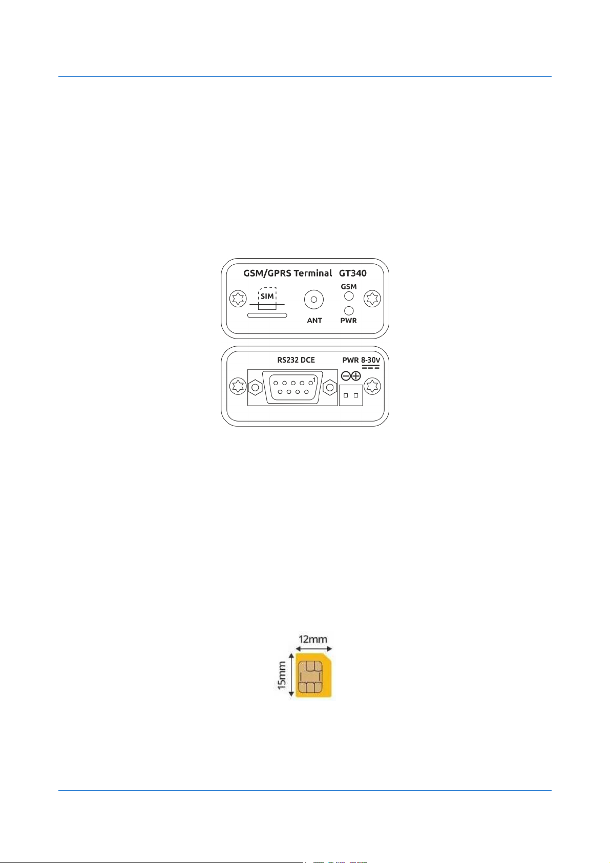
Front panel contains slot for micro SIM card, SMA connector for GSM antenna and LEDs for
indication of power supply and activity of GSM network.
Rear panel contains DB9 female connector for RS232 DCE serial interface and pluggable screw
clamp connector for DC power supply.
Fig. 2: Front and rear panel connectors
3.1 SIM card
Device supports standard Micro SIM card designed for 1.8V/3.0V voltage. SIM card holder is
push-push type.
Please pay attention to the direction of the card when inserting into the slot. Follow the
drawing on the front panel of the device.
Fig. 3: Micro SIM card
 Loading...