

Page 1
Deckorators® CXT 8' Rail Installation Instructions
PFS AA-652
For each 8' on-center railing section you will need:
One 8' Deckorators CXT Line or Stair Rail Kit that contains:
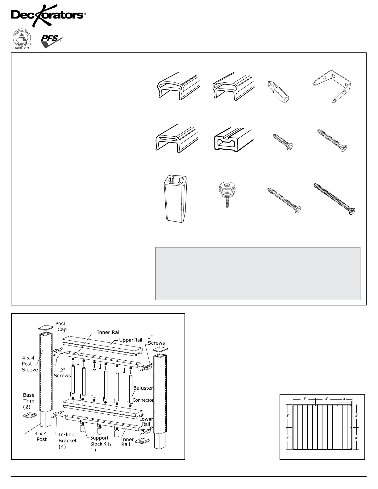
* (1) Upper rail
* (1) Lower rail
* (2) Inner rails
* (3) Support block kits that contain:
• 3 4" Support blocks
• 3 Support block connectors with screws
* (1) In-line or stair hardware kit that contains:
• 4 In-line or stair brackets
• 16 1" long countersunk screws
• 4 1-1/2" long pan head screws
• 8 2" long countersunk screws
• 2 2-1/2" long countersunk screws
• 1 Drill bit
• 1 Screw pack consisting of 40 screws
(use with Deckorators Baluster Connectors)
• 1 Post Sleeve Bracket placement template
Baluster options:
One Co-Extruded Composite Baluster Kit that contains:
• 20 – Balusters
• 40 – Baluster Connectors with screws
Classic, Estate, Twist or Ellipse baluster kits that each contain:
• 10 aluminum balusters
• 20 balusters needed per 8' on-center railing section
(Classic, Estate and Twist)
• 24 balusters needed per 8' on-center railing section (Ellipse)
and
Baluster connector or designer baluster connector kits
that each contain:
• 20 baluster connectors
• 1 kit needed per 10 balusters
Glass baluster kits that each contain:
• 5 glass balusters
• 20 stainless steel screws
• 12 balusters required per 8' on-center railing section
and
Glass baluster connector kits that each contain:
• 2 connectors
• 1 kit needed per baluster
Use rail kit without pre-drilled holes with Glass baluster kits.
One 40" or 52" Post Sleeve Kit that contains:
• 1 post sleeve
• 1 post base trim
One Post Cap for each post sleeve (sold separately)
For Installations Using Co-Extruded Composite,
Classic, Estate, Twist and Ellipse Balusters
Each Deckorators CXT Rail Kit
or
(1) - Upper rail (Colonial or Contemporary Style)
(1) - Lower rail
(3) - 4" Support blocks
Items you will need:
• Drill/power screwdriver
• Assorted drill bits
• Hammer
• Miter or circular saw with
fine-tooth carbide tip blade
(2) - Inner rails
(3) - Support block
connectors
with screws
• Construction adhesive
• Marked speed square
• Two clamps
• Carpenter’s level
• Carpenter’s pencil
(1) - Drill bit
(16) - 1" long
countersunk screws
(8) - 2" long
countersunk screws
• Adjustable wrench or socket
wrench for bolts, etc.
• Safety glasses/goggles
• Assorted fasteners
(see instructions)
• Tape measure
(4) - In-line or stair brackets
(4) - 1-1/2" long
pan head screws
(2) - 2-1/2" long
countersunk screws
Prior to construction, check with your local regulatory agency for
special code requirements in your area. Common railing heights are
36" and 42". Structural support should come from the continuation of
deck support posts that extend up through the deck floor or from railing
posts that are bolted to the inside of the rim or outer joists. Never
span more than 8' on-center between railing posts. Install railing posts
before deck boards are fastened to the joists.
Pre-drilling of all railing components is essential to successful
installation. Do not over-tighten screws. Read instructions completely
to get an understanding of how the product goes together and how each
piece affects the other.
Step 1: Determine the number
of railing posts needed for your
deck. Post spacing is 8' oncenter. Example: A 16'x20' deck
attached to a building with a
4' access opening on one side
will require a total of eight posts
3
(fig. 1).
fig. 1
6475_3/14
PAGE 1 - 8' CXT Rail_ENG
Page 2
8' Rail Installation Instructions continued
Step 2: Install rail posts prior to installing deck
boards. Cedar or pressure-treated pine 4x4 railing
posts provide the structural strength for the railing.
The length of each post is determined by the total
of the joist width (7-1/4") + decking thickness (1")
+ railing height (36" or 42") + spacing for post cap
(1-1/4") = 45-1/2" or 51-1/2".
Important: Do not notch the 4x4 railing posts. Notching
will reduce the strength of the post and could result in
railing collapse or failure.
Step 3: Position, plumb with a
level, and clamp the rail post on
the interior face of the joist. Plumb
again. The 4x4 railing post should
be bolted to the inside of the
joists using two 1/2"x6" galvanized
carriage bolts. Corner posts use a
third carriage bolt inserted through
the adjacent joist (fig. 2).
Step 4: Install decking; notch deck boards to fit around the 4x4 railing
posts. Allow 1/4" space between the deck boards and any permanent
structure or post. Additional blocking may be necessary on the 4x4 for
fastening deck boards.
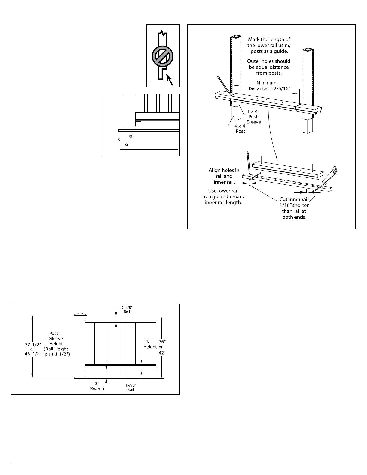
Step 5: Trim 4x4 post sleeves to length. Post sleeves should be a
minimum of 1-1/2" longer than the railing height to accommodate a post cap
(fig. 3). Example: For a 36" high railing, trim post sleeve to a minimum of
37-1/2"; can be left longer if desired. Slide a trimmed post sleeve over
each 4x4 railing post. Use shims as needed to create a snug fit. Slide a
post base trim over each post sleeve.
Step 6: Note! The rails are pre-drilled. To ensure the outer balusters are
equally spaced, the rail components require trimming at both ends. Ensure
the holes are a minimum of 2-5/16" from post. Using the lower pre-drilled
rail as a guide, place it adjacent to the post sleeves and center the rail
so the furthest pre-drilled holes for the balusters are equal distances
from the post sleeves. Mark the gap between the posts on to the lower
rail and trim to fit. Note! If using rails without pre-drilled holes, trim rail
components first, then mark baluster placement on lower rail and upper inner
rail, starting from the center of the rail. (Rails without pre-drilled holes are
used with glass baluster infill or other unique infill configurations).
fig. 3
Step 7: Note! To ensure the balusters are installed plumb, the holes between
the rail sections must all be aligned. Tip: Use a gauge pin or a 3/32" drill bit
to ensure the holes are aligned. Using the trimmed lower rail as a guide,
set one inner rail in the trimmed bottom rail and align the pre-drilled
holes. Mark the cut lines on the inner rail with a pencil. Note! To allow for
the thickness of the brackets, the inner rails should be 1/8" shorter than the
outer rails with all holes equally spaced. Remove an additional 1/16" from
the pencil mark on each end and trim the inner rail to length. Repeat for
the second inner rail (fig. 4).
fig. 2
fig. 4
Step 8: Assemble the lower inner rail and support block assembly. A
support block is needed every 2' on-center. Check building codes for a
maximum spacing between deck surface and bottom of rail (sweep). A 3"
sweep is recommended, but can be more or less if codes allow (fig. 3).
Trim support blocks to desired height and pre-drill 1/8" holes in the proper
location. Holes must be centered on the inner rail for support blocks to fit
properly. Using the support block connectors, fasten support blocks to the
underside of the inner rail.
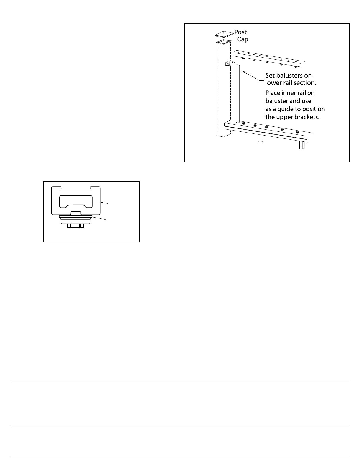
Step 9: Mark the height of the brackets on the inside of the post using
the bracket placement template included in the kit. Another option is
to use the inner rail as a guide. The top of the bracket should be even
with the top of the inner rail assembly. Drill two 1/8" holes through the
bracket holes shown on the template and through the post sleeve for both
the upper and lower brackets. Remove the bracket placement template
from the post sleeve and fasten the upper and lower brackets to the post,
using two 2" long countersunk screws. Tip: For best results, use a long drill
bit or add an extension bit to the drill. Repeat on the adjacent post. Set
the inner rail in between the lower brackets and pre-drill eight 1/8" holes
at each bracket hole and into the inner rail. Fasten the rail to the bracket
using eight 1" long countersunk screws.
Step 10: Set the lower rail on the lower inner rail between the posts.
Tip: Set the drill to the lowest setting when installing baluster connectors
and do not overdrive the screws. Using two 2-1/2" long countersunk screws,
set the two outermost baluster connectors in place. This will properly
align all pre-drilled holes. Using the screws provided with the baluster
connectors, install the balance of the baluster connectors onto the lower
rail assembly. If using Deckorators aluminum balusters with connectors,
use the 40-pack of 1" screws included with the rail kit. The screws
included with the Deckorators connectors are too long for use with the
CXT railing system.
PAGE 2 - 8' CXT Rail_ENG
Page 3
8' Rail Installation Instructions continued
Step 11: Determine the length of the balusters (fig. 3). Fig. 3 illustrates
how a 36" high railing might be sized. Starting with a 3" sweep + 2" for
the bottom railing, 29" baluster height + 2" for the top rail = a 36" rail
height. If these are the dimensions that you are going to use, cut the
balusters to 29" length using a cut-off or miter saw. Use 35" balusters for
42" railings. If you want to have your railing at a different height, use fig.
3 as a planning tool to determine the height to cut the post sleeves and
the balusters. If you are using 32" glass balusters, your overall railing height
will be 39". Note: Use a fixture to ensure a consistent length (+/- 1/16"). Trim
the balusters to the required length. Install balusters on each baluster
connector. Gently tap the balusters with a rubber mallet to eliminate any
gaps. Check for level end to end. Tip: Wrap painters tape around the back
side of both posts and place balusters against the tape. The tape will balance
the balusters in place until the upper rails are installed. Remove tape when
upper rail is in place.
Step 12: Important: When using Deckorators Designer Baluster Connectors
(both Estate and Classic), the upper inner rail must be inverted (fig. 5). Use
an exterior adhesive on the underside of the Designer Baluster Connectors to
prevent the balusters from spinning. Install the baluster connectors on the
underside of the top inner rail (fig. 6). Set the rail on to the balusters, gently
tapping the rail to remove any gaps. Attach the inner rail to the brackets
by pre-drilling eight 1/8" holes at each bracket hole and into the inner rail.
Fasten the rail to the bracket using eight 1" long countersunk screws.
Inverted
Inner
Rail
Designer
Baluster
Connector
fig. 5
fig. 6
Step 13: Measure the distance between the posts and trim the upper top rail
to length and set on the assembly. Taking care not to drill all the way through
the upper rail, use a 1/8" drill bit to pre-drill four 1-1/2" deep holes, equally
spaced, through the underside of the inner rail and into the underside of the
upper rail. Tip: Place a piece of tape 1-1/2" from the end of the drill bit. Do not
drill past the tape. Fasten cap rail in place using four 1-1/2" pan head screws.
Step 14: Apply construction adhesive to the inside edges of the post caps and
place over each post sleeve.
Note: Touch-up paint is available to repair any chips or blemishes that occur
during assembly and installation. Contact a Deckorators customer service
agent at 800-332-5724 for availability.
Deckorators is not suitable for structural use. It should not be used for primary load-bearing members such as posts, joists, beams or stringers. The same common-sense precautions should be taken
when handling Deckorators as with wood or other building materials. Dust masks and eye protection devices are recommended to avoid possible irritation from sawdust and chips. Gloves will help to
protect the hands. Hands should be washed after doing construction work.
The diagrams and instructions in this brochure are for illustration purposes only and are not meant to replace a licensed professional. Any construction or use of the product must be in accordance with
all local zoning and/or building codes. The consumer assumes all risks and liability associated with the construction or use of this product. The consumer or contractor should take all necessary steps
to ensure the safety of everyone involved in the project, including, but not limited to, wearing the appropriate safety equipment. EXCEPT AS CONTAINED IN THE WRITTEN LIMITED WARRANTY,
WARRANTOR DOES NOT PROVIDE ANY OTHER WARRANTY, EITHER EXPRESS OR IMPLIED, AND SHALL NOT BE LIABLE FOR ANY DAMAGES, INCLUDING CONSEQUENTIAL DAMAGES.
Manufactured by UFP Ventures II, Inc., a Universal Forest Products Company, 801 E. Lessard, Prairie du Chien, WI 53821 877.463.8379
©2012, 2014 Universal Forest Products, Inc. All rights reserved. Deckorators is a registered trademark of Universal Consumer Products, Inc. in the U.S. and other countries.
ASTM D 7032 compliant. See CCRR-0171 at www.ati-es.com for uses and performance levels. 6475_3/14
www.deckorators.com
PAGE 3 - 8' CXT Rail_ENG
Page 4

PFS AA-652
Deckorators® CXT Instructions d'installation de traverse de 8 pi
Pour les installations utilisant des balustres co-profilés
Composite, Classique, Estate, Twist ou Ellipse
Pour chaque section de traverse centre-à-centre de 8 pi,
vous aurez besoin de ce qui suit:
Une trousse de traverses en ligne Deckorators CXT de 8 pi qui contient :
* (1) traverse supérieure
* (1) traverse inférieure
* (2) traverses intérieures
* (3) trousses de blocs de support :
• 3 blocs de support de 4 po
• 3 raccords de bloc de support avec vis
* (1) trousse de quincaillerie d'escalier ou en ligne,qui contient :
• 4 fixations d'escalier ou en ligne
• 16 longues vis à tête fraisée de 1 po
• 4 longues vis à tête cylindrique de 1 1/2 po
• 8 longues vis à tête fraisée de 2 po
• 2 longues vis à tête fraisée de 2 1/2 po
• 1 foret de perceuse
• 1 paquet de vis comprenant 40 vis
(à utiliser avec les raccords de balustres Deckorators)
• 1 modèle de placement de fixations de manchons de poteaux
Options de balustres :
Une trousse de balustres composites co-profilés qui contient :
balustres
• 20 –
• 40 – raccords de balustres avec vis
Trousses de balustres Classique, Estate, Twist ou Ellipse qui
contiennent chacune :
• 10 balustres d'aluminium
• 20 balustres nécessaire par section de traverses de 8 pi
centre-à-centre (Classic, Estate et Twist)
• 24 balustres nécessaire par section de traverses de 8 pi
centre-à-centre (Ellipse)
et
Trousses de raccord de balustres de designers ou raccord de balustre
qui contiennent chacune :
• 20 raccords de balustres
• 1 trousse nécessaire par 10 balustres
Verre,
Trousse de balustre
• 5 balustres de verre
• 20 vis d’acier inoxydable
• 12 balustres requis par section de 8 pi de traverse centre-à-centre
et
Trousses de raccord de balustres Verre, qui contiennent chacune :
• 2 raccords
• 1 trousse nécessaire par balustre
Utiliser la trousse de rampe sans trous prépercés avec les ensembles
de balustres de verre.
Une trousse de manchons de poteaux de 40 ou 52 po qui contient :
• 1 manchon de poteau
• 1 garniture de base de poteau
Un capuchon de poteau pour chaque manchon de poteau (vendu séparément)
qui contient :
Chaque trousse de traverses Deckorators CXT inclut :
ou
(1) - traverse supérieure
(Style colonial ou contemporain)
(1) - traverse inférieure
(2) - blocs de support
de 4 po
(2) - traverses
intérieures
(3) - raccords de
bloc de support
avec vis
(16) - longues vis à
tête fraisée de 1 po
(8) - longues vis à
tête fraisée de 2 po
Articles dont vous aurez besoin
• Tournevis électrique
• Forets de perceuse assortis
• Marteau
• Scie circulaire ou à onglets
avec lame à pointe fine
au carbure
• Adhésif de construction
• Équerre
• Deux serre-joints
• Niveau à bulle
• Crayon de menuisier
(1) - foret de
perceuse
(4) - fixations d'escalier
ou en ligne
(4) - longues vis à tête
cylindrique de 1 1/2 po
(2) - longues vis à tête
fraisée de 2 1/2 po
• Clé ou clé à douille ajustable
pour boulons, etc.
• Lunettes de protection
• Dispositifs de fixation agencés
(voir instructions)
• Ruban à mesurer
4 x 4
Manchon
de poteau
Couvre-
(2)
joint
Poteau
4 x 4
Capuchon
de poteau
Vis
2 po
Fixations
en-ligne
(4)
Traverse intérieure
Trousses
de blocs
de support (3)
Traverse supérieure
Vis 1 po
Balustre
Raccord
Traverse
inférieure
Traverse intérieure
Avant la construction, informez-vous auprès de votre municipalité afin de
connaître la réglementation. Les hauteurs habituelles des balustrades
sont de 36 po et de 42 po. Le soutien de la structure devrait provenir
de la continuité des poteaux de soutien de la terrasse qui se prolongent
jusqu’au plancher ou des poteaux de rampe qui sont fixés à l’intérieur
ou à l’extérieur sur le bord des solives. Ne laissez jamais plus de 6 pi
d’écart entre les poteaux pour une section de traverse de centre à centre.
Installez les poteaux avant de fixer les lames de terrasses sur les solives.
Il est essentiel de prépercer tous les éléments de la balustrade afin
que l’installation soit un succès. Ne serrez pas trop les vis. Lisez les
instructions au complet afin de bien comprendre comment assembler le
produit et comment chaque pièce se fixe à l’autre.
Étape 1 : Calculez le nombre de
poteaux pour balustrades dont
vous aurez besoin pour votre
terrasse. Les poteaux doivent
être espacés de 8 pi de centre
à centre. Exemple : Une terrasse
de 16 pi x 20 pi fixée à un
immeuble avec une ouverture de
4 pi sur le côté afin d’y accéder
demandera 8 poteaux (fig.1).
fig. 1
6475_3/14
PAGE 1 - 8' CXT Rail_FRE
Page 5

Instructions d'installation de traverse de 8 pi suite
Étape 2 : Installez les poteaux pour balustrade avant de fixer
les lames de terrasse. Les poteaux pour balustrade en cèdre
ou en pin traité sous pression sont la force structurale de la
balustrade. La longueur de chaque poteau est déterminée par
le total des largueurs des solives (7-1/4 po) + l’épaisseur des
lames (1 po) + la hauteur de la balustrade (36 po ou 42 po)
+ l’espacement pour les capuchons de poteaux (1-1/4 po) =
45-1/2 po ou 51-1/2 po.
Important : N’entaillez pas les poteaux pour
balustrade 4x4. Entailler un poteau réduira
sa force et pourrait causer l’effondrement
ou l’échec de la construction.
Étape 3 : Placez, nivelez et serrez à l’aide
d’un serre-joint le poteau pour balustrade sur
la face inférieure de la solive. Nivelez encore.
Le poteau 4x4 devrait être fixé à l’intérieur
des solives avec des boulons de carrosserie
galvanisés de ½ po x 6 po. Pour les poteaux dans les coins, utilisez un
troisième boulon que vous fixerez à la solive adjacente (fig. 2).
Étape 4 : Installez les lames : entaillez les lames afin qu’elles se placent avec
les poteaux pour balustrade 4x4. Laissez un espacement de ¼ po entre les
lames, toute structure permanente ou tout poteau. Un blocage additionnel
pourrait être nécessaire pour les 4x4 afin de fixer les lames de terrasse.
Étape 5 : Taillez les manchons de poteaux 4x4 pour la longueur. Les
manchons de poteaux devraient être d'au moins 1-1/2 po plus longs que
la hauteur de la traverse pour accommoder un capuchon de poteau (fig.
3). Exemple – pour une traverse de 36 po de haut, taillez le manchon à
au moins 37-1/2 po, mais peut être plus long si vous le désirez. Glissez
un manchon de poteau taillé sur chaque poteau de traverse de 4x4.
Utiliser des cales au besoin pour obtenir un ajustement serré. Glissez
une garniture de base de poteau sur chaque manchon de poteau.
Étape 6 : Remarque! Les traverses sont pré-percées. Pour assurer que les
balustres extérieurs soient espacés de manière égale, les éléments de la traverse
doivent être taillés aux deux extrémités. Assurez-vous que les trous sont à au
moins 2-5/16 po du poteau. Utilisez la traverse inférieure pré-percée comme
guide et placez-la près des manchons de poteau et centrez la traverse pour
que les trous pré-percés les plus loin des balustres soient à des distances
égales des manchons de poteaux. Marquez l'écart entre les poteaux sur
la traverse inférieure et taillez pour ajuster. Remarque! Si vous utilisez des
traverses sans trous pré-percés, taillez d’abord les composants de traverses,
puis marquez l’emplacement de balustres sur la traverse inférieure et la traverse
intérieure supérieure en commençant du centre de la traverse. (Les rampes
sans trous prépercés sont utilisées avec les éléments de remplissage de
balustre de verre ou autres configurations uniques de remplissage).
Hauteur
de la couverture
de poteau
(hauteur du
balustre +
1-1/2 po)
37-1/2 po
ou
43-1/2 po
fig. 3
3 po
distance
Étape 7 : Remarque! Pour assurer que les balustres sont installés à niveau,
les trous entre les sections des traverses doivent tous être alignés. Conseil :
Utilisez un clou de cloueuse ou un foret de perceuse de 3/32 po pour assurer
l'alignement des trous. Utilisez la traverse inférieure taillée comme guide,
installez une traverse intérieure dans la traverse inférieure taillée et alignez
les trous pré-percés. Marquez les lignes de coupe de la traverse intérieure
avec un crayon. Remarque! Pour tenir compte de l'épaisseur des fixations,
les traverses intérieures devraient être 1/8 po plus courtes que les traverses
fig. 2
Traverse 2-1/8 po
Hauteur
de la
balustrade
Traverse
36 po
ou
42 po
Tracez la longueur
de la traverse inférieure
en utilisant les poteaux
comme guide.
Les trous
devraient être
à distance égale
des poteaux
Distance
minimale = 2-5/16 po
Manchon
de poteau
Poteau
Alignez les trous
de la traverse et de
la traverse intérieure
Utilisez la traverse
inférieure comme
guide afin de tracer
la longueur de la
traverse intérieure
fig. 4
Coupez la traverse intérieure
1/16 po plus court que
la rampe, et ce,
à chaque extrémité
extérieures avec tous les trous espacés de manière égale. Retirez un autre
1/16 po de la marque de crayon à chaque extrémité et taillez la traverse
intérieure à la longueur. Répétez pour la deuxième traverse intérieure (fig. 4).
Étape 8 : Assemblez la traverse intérieure inférieure et l'assemblage du
bloc de support. Il faut un bloc de support à tous les 2 pi de centre-àcentre. Vérifiez les exigences du code de la construction pour l'espacement
maximum entre la surface de la terrasse et le bas de la traverse (balayage).
Un espacement de 3 po est recommandé, mais peut être plus ou moins
si les codes le permettent (fig. 3). Taillez les blocs de support à la
hauteur voulue et pré-percez des trous de 1/8 po au bon endroit. Les
trous devraient être centrés sur la traverse intérieure pour que les blocs de
support s'ajustent correctement. Utilisez les raccords de blocs de support
et attachez les blocs de supports sous la traverse intérieure.
Étape 9 : Marquez la hauteur des fixations à l'intérieur du poteau en
utilisant le modèle de placement des fixations inclus dans la trousse. Une
autre option est d'utiliser la traverse intérieure comme guide. Le dessus
de la fixation devrait être à niveau avec le dessus de l'assemblage de la
traverse intérieure. Percez deux trous de 1/8 po à travers les trous de
fixation indiqués sur le modèle et à travers le manchon du poteau pour
les fixations supérieures et inférieures. Retirez le modèle de placement
du manchon du poteau et attachez les fixations supérieures et inférieures
au poteau avec les vis à tête fraisée de 2 po. Conseil : Pour les meilleurs
résultats, utilisez un long foret de perceuse ou ajoutez une rallonge de foret à
la perceuse. Répétez sur le poteau adjacent. Installez la traverse intérieure
entre les fixations inférieures et pré-percez huit trous de 1/8 po à chaque
trou de fixation et dans la traverse intérieure. Attachez la traverse à la
fixation en utilisant huit vis à tête fraisée de 1 po.
Étape 10 : Installez la traverse inférieure sur la traverse intérieure
inférieure entre les poteaux. Conseil : Réglez la perceuse au réglage le plus
bas en installant les raccords de balustres et ne resserrez pas trop les vis.
Utilisez deux longues vis fraisées de 2 1/2 po, installez les deux raccords de
balustres le plus éloignés en place. Ceci permettra d'aligner correctement
tous les trous pré-percés. Utilisez les vis fournies avec les raccords de
balustre et installez le reste des raccords de balustres dans l'assemblage
de traverse inférieur. Si vous utilisez des balustres d'aluminium Deckorators
avec raccords, utilisez le paquet de 40 vis de 1 po inclus dans la trousse de
traverse. Les vis incluses avec les raccords Deckorators sont trop longues
pour les utiliser avec le système de traverse CXT.
PAGE 2 - 8' CXT Rail_FRE
Page 6

Instructions d'installation de traverse de 8 pi suite
Étape 11 : Calculez la longueur des balustres (fig. 3). La Fig. 3 montre
comment une balustrade de 36 po devrait être dimensionnée. En
commençant avec une distance de 3 po au bas + 2 po à partir du pied
de la balustrade + des balustres d’une hauteur de 29 po + 2 po pour la
rampe de dessus = une balustrade d’une hauteur de 36 po. Si ce sont les
dimensions que vous utiliserez, coupez des balustres d’une longueur de 29
po en utilisant une ébouteuse ou une scie à onglet. Coupez des balustres de
35 po pour une balustrade de 42 po de hauteur. Si vous voulez que votre
balustrade soit d’une hauteur différente, référez-vous à la fig.3 comme outil de
planification afin de déterminer la hauteur dont vous couperez les manchons
de poteaux et les balustres. Si vous utilisez des balustres de verre de 32 po, votre
hauteur de balustrade d’ensemble sera de 39 po. Remarque : Utilisez un portepièce afin de vous assurer d’une longueur constante (+/- 1/16 po). Taillez les
balustres de la bonne longueur. Placez les balustres dans chaque embout de
balustre. Tapez doucement sur les balustres avec un maillet en caoutchouc
afin d’éliminer tout espacement possible. Nivelez d’un bout à l’autre.
Conseil : Enroulez du ruban pour peintre autour de l'arrière des deux poteaux
et placez les balustres contre le ruban. Le ruban équilibrera les balustres en
place jusqu'à ce que les traverses supérieures soient installées. Retirez le ruban
lorsque la traverse supérieure est en place.
Étape 12 : Important : en utilisant les raccords de balustre Deckorators Designer
(Estate et Classic), la traverse intérieure supérieure doit être inversée (fig.
5). Utilisez un adhésif extérieur sous les raccords de balustre Designer pour
éviter que les balustres pivotent. Installez les raccords de balustre sous la
traverse intérieure supérieure (fig. 6). Installez la traverse sur les balustres,
frappez délicatement la traverse pour retirer tous écarts. Installez la traverse
intérieure aux fixations en pré-perçant huit trous de 1/8 po à chaque trou
de fixation et dans la traverse intérieure. Attachez la traverse à la fixation en
utilisant huit vis à tête fraisée de 1 po.
Capuchon
de poteau
Placez les balustres
sur la section de
traverse inférieure
Placez la traverse intérieure
du balustre et utilisez comme
guide pour placer les fixations
supérieures
fig. 6
Étape 13 : Mesurez la distance entre les poteaux et taillez la traverse la plus
haute à la longueur et placez sur l'assemblage. Attention de ne pas percer
complètement à travers la traverse supérieure, utilisez un foret de perceuse
de 1/8 po pour pré-percer quatre trous de 1 1/2 po de profondeur, espacés
uniformément, sous la partie inférieure de la traverse intérieure et dans le
dessous de la traverse supérieure. Conseil : Placez un morceau de ruban adhésif
à 1 1/2 po de l'extrémité du foret de perceuse. Ne dépassez pas cet endroit
en perçant. Installez la traverse à chapeau en place avec quatre vis à tête
cylindrique de 1 1/2 po.
Étape 14 : Posez un adhésif de construction sur les côtés intérieurs des
capuchons de poteaux et placez ceux-ci sur chaque manchon de poteau.
Remarque : Une peinture de retouche est disponible pour réparer tous
copeaux ou défauts du fini qui pourraient apparaître durant l'assemblage et
Traverse
intérieure
inversée
Raccord de
balustres
Designer
l'installation. Contactez un agent du service à la clientèle Deckorators au
800-332-5724 pour connaître la disponibilité.
fig. 5
Deckorators est ne conviennent pas pour une utilisation structurelle. Elles ne devraient pas servir comme composantes ayant à supporter des charges importantes comme les poteaux, les solives, les
poutres ou les limons. Les mêmes précautions que l’on prend avec le bois ou d’autres matériaux de construction devraient être prises lors de la manipulation de produits Deckorators. Des masques
protecteurs contre la poussière et du matériel qui protège les yeux sont recommandés afin d’éviter les irritations produites par les copeaux et les sciures de bois. Porter des gants protégera les mains.
Les mains devraient toujours être lavées après un travail de construction. Les diagrammes et les instructions contenus dans cette brochure sont présents à des fins d’illustration seulement et ne
remplacent pas un professionnel accrédité. Toute construction ou toute utilisation de ce produit doit être conforme aux codes de la construction et/ou aux règlements de zonage. Le consommateur
assume tous les risques et responsabilités associés à la construction du produit. Le consommateur ou l’entrepreneur devrait prendre les mesures nécessaires afin d’assurer la sécurité de tous ceux qui
font partie d’un projet, incluant, mais qui ne se limite pas seulement à ça, le port d’équipement de sécurité approprié. À L’EXCEPTION DE CE QUI EST ÉCRIT POUR LA GARANTIE LIMITÉE, LE GARANT NE
FOURNIT AUCUNE AUTRE GARANTIE, QU’ELLE SOIT IMPLICITE OU EXPLICITE, ET NE DEVRAIT PAS ÊTRE TENU RESPONSABLE DES DOMMAGES, INCLUANT LES DOMMAGES INDIRECTS.
Fabriqué par UFP Ventures II, Inc., une société Universal Forest Products 1801 E. Lessard, Prairie du Chien, WI 53821 877.463.8379
©2012, 2014 Universal Forest Products, Inc. Tous droits réservés. Deckorators est une marque de commerce de Universal Consumer Products, Inc., aux États-Unis.
Conforme à la norme ASTM D 7032. Voir les usages et les niveaux de performance du produit dans le rapport CCRR-0171, à l'adresse www.ati-es.com 6475_3/14
www.deckorators.com
PAGE 3 - 8' CXT Rail_FRE
Page 7

Deckorators® CXT
PFS AA-652
Para cada sección de barandal de 8 pies de centro a centro necesitará:
Un kit de barandal en línea Deckorators CXT de 8 pies, que contiene:
* (1) Barandal superior
* (1) Barandal inferior
* (2) Barandales interiores
* (3) Kits de bloque de apoyo, que contiene:
• 3 Bloques de soporte de 4"
• 3 Conectores para bloque de soporte con tornillos
* (1) Kit de herrajes de barandal en línea o barandal para
escaleras, que contiene:
• 4 Soportes en línea o para escalera
• 16 Tornillos avellanados de 1" de longitud
• 4 Tornillos de cabeza cónica de 1-1/2" de longitud
• 8 Tornillos avellanados de 2" de longitud
• 2 Tornillos avellanados de 2-1/2" de longitud
• 1 Cabeza de taladro
• 1 Paquete de tornillos con 40 tornillos
(úsese con los conectores para balaustre Deckorators)
• 1 Plantilla para colocar soportes con cobertura para poste
Opciones de balaustre:
Un kit de balaustres coextrudidos Composite, que contiene:
• 20 – Balaustres
• 40 – Conectores de balaustres con tornillos
Kits de balaustres Classic, Estate, Twist o Ellipse de aluminio, que contienen:
• 10 balaustres de aluminio
• 20 balaustres necesarios por cada sección de barandal de 8' de
centro a centro (Classic, Estate y Twist)
• 24 balaustres necesarios por cada sección de barandal de 8' de
centro a centro (Ellipse)
y
Kits de conector de balaustre o de conector de balaustre de diseñador
que contenga cada uno:
• 20 conectores de balaustre
• 1 kit necesario por 10 balaustres
Kits de balaustres de vidrio, que contienen:
• 5 balaustres de vidrio
• 20 tornillos de acero inoxidable
• 12 balaustres necesarios por cada sección de barandal de 8' de
centro a centro
y
Kits de conector de balaustres de vidrio, que contienen:
• 2 conectores
• 1 kit necesario por balaustre
Utilice el kit para barandales agujeros perforados con los kits de
balaustre de vidrio.
Un kit de cobertura para poste de 40" ó 52", que contiene:
• 1 cobertura para poste
• 1 guarda para base de poste
Un tope para poste por cada cobertura para poste (se vende por separado)
Instrucciones de instalación de barandal de 8 pies
Para instalaciones que usan balaustres coextrudidos
Composite, Classique, Estate, Twist y Ellipse
Cada kit de barandal Deckorators CXT incluye:
o
(1) - Barandal superior
(Estilos Colonial o Contemporary)
(1) - Barandal inferior
(2) - Bloques de
soporte de 4"
soporte con tornillos
Qué necesitará:
• Taladro/desarmador eléctrico
• Cabezas de taladro diversas
• Martillo
• Sierra ingletadora o circular
con hoja de punta de carburo
(2) - Barandales
interiores
Conectores
(2) -
para bloque de
• Adhesivo para
construcción
• Escuadra graduada
• Dos abrazaderas
• Nivel de carpintero
• Lápiz de carpintero
(1) - Cabeza de
taladro
(16) - Tornillos
avellanados de 1"
de longitud
(8) - Tornillos
avellanados de 2"
de longitud
(4) - Soportes en línea
o para escalera
(4) - Tornillos de
cabeza cónica de
1-1/2" de longitud
(2) - Tornillos
avellanados de
2-1/2" de longitud
• Llave ajustable o dados
para pernos,etc.
• Lentes de seguridad
• Herrajes variados
(vea las instrucciones)
• Cinta métrica
Tornillos
de 2"
Antes de iniciar la construcción, consulte con la agencia reguladora local
sobre requisitos especiales de la reglamentación en su área. Las alturas
comunes de los barandales son de 36" y 42". El soporte estructural
debe provenir de la continuación de los postes de soporte de la terraza
que se extienden hacia arriba a través del piso de la terraza o de los
postes del barandal que están atornillados al interior del borde o de las
vigas exteriores. Nunca deje una distancia de más de 8' al centro entre
los postes del barandal. Instale los postes del barandal antes de fijar el
entablado de la terraza a las vigas.
La perforación previa de todos los componentes del barandal es esencial
para la instalación exitosa. No apriete demasiado los tornillos. Lea las
instrucciones completamente para comprender el ensamblado del
producto y cómo se afectan las piezas entre sí.
Paso 1: Determine el número de
postes del barandal necesarios
para su terraza. El espaciado
de los postes es de 8' al centro.
Ejemplo: Una terraza de 16'x20'
fija a una construcción con una
3
abertura de acceso de 4' en un
costado requerirá un total de
ocho postes (Figura 1).
fig. 1
6475_3/14
PAGE 1 - 8' CXT Rail_SPA
Page 8

Instrucciones de instalación de barandal de 8 pies continuación
Paso 2 : Instale los postes para barandal antes de instalar el entablado de
la terraza. Los postes de barandal de 4x4 de cedro o pino tratado a presión
proporcionan la fuerza estructural para el barandal. La longitud de cada
poste se determina mediante el total del ancho de la viga (7-1/4") + el grosor
del entablado (1") + altura del barandal (36" o 42") + espaciado para el tope
para poste (1-1/4") = 45-1/2" o 51-1/2".
Importante: No haga muescas en los postes del barandal de
4x4. Las muescas reducirán la fuerza del poste y pueden
tener como resultado la ruptura o falla del barandal.
Paso 3 : Coloque y aplome con un nivel y asegure el poste
del barandal sobre la cara interior de la viga. Nivele de nuevo.
El poste de barandal de 4x4 deberá atornillarse al interior de
las vigas usando dos pernos de cabeza redonda galvanizados
de 1/2"x6". Los postes de esquinas usan un
tercer perno de cabeza redonda insertado a
través de la viga adyacente (Figura 2).
Paso 4 : Instale el tablado, corte las tablas
de la terraza para ajustarlas alrededor de
los postes del barandal de 4x4. Deje un
espacio de 1/4" entre las tablas de la terraza
y cualquier estructura o poste permanente.
Puede ser necesario un bloqueo adicional en
el 4x4 para fijar las tablas de la terraza.
Paso 5 : Recorte las coberturas para poste de 4x4 a la longitud deseada. Las
coberturas para poste deberán ser mínimo 1-1/2" más largas que la altura
del barandal para acomodar un tope para poste (Figura 3). Ejemplo: Para un
barandal de 36" de alto, recorte la cobertura para poste a un mínimo de 371/2", puede dejarse más largo si así lo desea. Deslice una cobertura de poste
recortada sobre cada poste de barandal de 4x4. Utilice los suplementos
según sea necesario para crear un ajuste cómodo. Deslice una guarda para
base de poste sobre cada cobertura para poste.
Paso 6: ¡Nota! Los barandales están pre-perforados. Para asegurar que los
balaustres externos tengan un espacio igual entre los mismos, los componentes
del barandal necesitan recortarse en ambos extremos. Asegúrese que los
orificios estén a un mínimo de 2-5/16" de cada poste. Usando el barandal
inferior pre-perforado como guía, colóquelo junto a las coberturas para poste
y centre el barandal para que los orificios pre-perforados más alejados para
los balaustres estén a igual distancia que las coberturas para postes. Marque
la brecha entre los postes en el barandal inferior y recórtelo para que se
ajuste. ¡Nota! Si usa barandales sin orificios pre-perforados, primero ajuste los
componentes del barandal, después marque la colocación del balaustre sobre el
barandal inferior y el barandal interior superior, comenzando desde el centro del
barandal. (Los barandales sin agujeros perforados se utilizan con el balaustre
de vidrio para relleno u otras configuraciones exclusivas de relleno).
fig. 3
Paso 7: ¡Nota! Para asegurar que los balaustres estén instalados a plomo, los
orificios entre las secciones de los barandales deben todos estar alineados.
Consejo: Use un calibrador o una cabeza de taladro de 3/32" para comprobar que
los orificios estén alineados. Usando el barandal inferior recortado como guía,
coloque un barandal interior en el barandal inferior recortado y alinee los
orificios pre-perforados. Marque las líneas de corte en el barandal inferior con
un lápiz. ¡Nota! Para permitir el paso del grosor de los soportes, los barandales
interiores deberán ser 1/8" más cortos que los barandales exteriores con todos
los orificios espaciados de la misma forma. Quite 1/16" adicional de la marca
fig. 2
fig. 4
de lápiz en cada extremo y recorte el barandal interior a la longitud debida.
Repita para el segundo barandal interior (Figura 4).
Paso 8: Ensamble el barandal interior inferior y el conjunto de bloque de
apoyo. Se requiere un bloque de soporte cada 2 pies de centro a centro.
Revise los requisitos del código de construcción para el espaciamiento
máximo entre la superficie de la terraza y la parte inferior del barandal
(barrido). Se recomienda un barrido de 3" pero puede ser mayor o menor
si lo permiten los códigos (figura 3). Recorte los bloques de soporte a la
altura deseada y pre-perfore orificios de 1/8" en la ubicación adecuada. Los
orificios deben estar centrados en el barandal interior para que los bloques
de soporte se ajusten correctamente. Utilice los conectores de los bloques de
soporte para asegurar dichos bloques en el lado inferior del barandal interior.
Paso 9: Marque la altura de los soportes en la cara interna del poste con la
plantilla de colocación de soporte que se incluye en el kit. Otra opción es
utilizar el barandal interno como guía. La parte superior del soporte deberá
estar nivelada con la parte superior del conjunto de barandal interior. Perfore
dos orificios de 1/8" a través de los orificios de los soportes tal como se
muestra en la plantilla y a través de la cobertura del poste, tanto para el
soporte superior como inferior. Retire la plantilla de colocación de los soportes
de la cobertura del poste y asegure los soportes superior e inferior al poste
con dos tornillos avellanados de 2" de longitud. Consejo: Para obtener mejores
resultados, utilice una cabeza de taladro larga o añada una cabeza de extensión
al taladro. Repita en el poste adyacente. Coloque el barandal interior entre
los soportes inferiores y pre-perfore ocho orificios de 1/8" en cada orificio de
soporte y en el riel interior. Sujete el riel en el soporte usando ocho tornillos
avellanados de 1" de longitud.
Paso 10: Ajuste el barandal inferior en el barandal interior inferior entre
los postes. Consejo: Ajuste el taladro en la configuración más baja al instalar
conectores de balaustre y no atornille demasiado fuerte los tornillos. Usando
dos tornillos avellanados de 2-1/2" de longitud, coloque en su lugar los dos
conectores de balaustre de los extremos. De esta manera, quedarán alineados
todos los orificios pre-perforados. Usando los tornillos proporcionados con los
conectores de balaustres, instale el balance de los conectores de balaustres
en el conjunto del barandal inferior. Si está utilizando balaustres de aluminio
Deckorators con los conectores, utilice el paquete de 40 tornillos de 1" que se
incluyen en el kit del barandal. Los tornillos que se incluyen con los conectores
Deckorators son demasiado largos para usarse con el sistema de barandales CXT.
PAGE 2 - 8' CXT Rail_SPA
Page 9

Instrucciones de instalación de barandal de 8 pies continuación
Paso 11: Determine la longitud de los balaustres (Figura 3). La Figura
3 ilustra cómo puede medirse un barandal de 36" de alto. Comenzando
con un espacio de 3" + 2" para el barandal inferior, + 29" de altura del
balaustre + 2" para el barandal superior = una altura de barandal de 36".
Si estas son las dimensiones que utilizará, corte los balaustres a una
longitud de 28-1/2" usando una sierra de corte o de mesa. Use balaustres
de 35" para barandales de 42". Si usted desea tener su barandal a una
altura diferente, use la Figura 3 como una herramienta de planeación
para determinar la altura de corte de las coberturas para poste y los
balaustres. Si usa balaustres de vidrio de 32", la altura general del barandal
será de 39". Nota: Use una herramienta para asegurar una longitud consistente
(+/- 1/16”). Corte los balaustres a la longitud requerida. Instale los
balaustres en cada conector para balaustres. Martille suavemente los
balaustres con un mazo de goma para eliminar cualquier separación.
Revise el nivel de extremo a extremo. Consejo: envuelva la parte posterior de
ambos postes con cinta y coloque los balaustres contra ésta. La cinta ayudará
a equilibrar los balaustres en su lugar hasta que haya instalado los rieles
superiores. Después, retire la cinta.
Paso 12: Importante: al utilizar los conectores para balaustres Deckorators
Designer (tanto Estate como Classic), debe invertirse el barandal superior
interior (figura 5). Use un adhesivo para exteriores en el lado inferior de los
conectores para balaustres Designer para evitar que los balaustres giren. Instale
los conectores de balaustre en la parte de abajo del barandal interior superior
(figura 6). Coloque el barandal en los balaustres, dando golpecitos suaves en
el barandal para eliminar cualquier separación. Acople el barandal interior
a los soportes. Para esto, pre-perfore ocho orificios de 1/8" en cada orificio
de soporte y en el barandal interior. Sujete el barandal en el soporte usando
ocho tornillos avellanados de 1" de longitud.
Barandal
interior
invertido
Conector
de balaustre
Designer
fig. 5
Coloque el barandal interior
en los balaustres y úselo como
guía para colocar los soportes
superiores
fig. 6
Paso 13: Mida la distancia entre los postes y recorte el barandal superior a
la longitud deseada y ajuste en el ensamble. Con cuidado para no perforar por
completo el barandal superior, utilice una cabeza de taladro de 1/8" para preperforar cuatro orificios de 1-1/2" separados a una distancia uniforme entre sí, a
través de la cara inferior del barandal interior y en la cara inferior del barandal
superior. Consejo: Coloque un trozo de cinta a una distancia de 1-1/2" del extremo
de la cabeza de taladro. No perfore más allá de la cinta. Fije el barandal de tapa
en su lugar usando los cuatro tornillos de cabeza plana de 1-1/2".
Paso 14 : Aplique adhesivo de construcción a los bordes interiores de las
tapas de poste y colóquelas sobre cada cobertura para poste.
Nota: Existe pintura para retocar disponible para reparar cualquier astilla o
marca que ocurra durante el ensamble y la instalación. Comuníquese con el
representante de servicio a clientes de Deckorators al teléfono 800-332-5724
para consultar la disponibilidad.
Deckorators no es adecuado para uso estructural. No deberá utilizarse para elementos de carga primarios como postes, travesaños, vigas o largueros. Las mismas precauciones de sentido común
deberán tomarse al manejar Deckorators así como madera u otros materiales de construcción. Se recomienda usar mascarillas contra polvo y dispositivos de protección ocular para evitar la posible
irritación causada por aserrín y astillas. Los guantes lo ayudarán a proteger sus manos. Debe lavarse las manos después de realizar trabajo de construcción.
Los diagramas e instrucciones en este folleto son sólo para fines de ilustración y no reemplazan a un profesional autorizado. Cualquier construcción con el, o uso del, producto debe hacerse de acuerdo
con todos los códigos locales de planificación urbana y/o de construcción. El consumidor asume todo riesgo y responsabilidad asociados con la construcción o uso de este producto. El consumidor
o contratista debería tomar todos los pasos necesarios para garantizar la seguridad de todos los involucrados en el proyecto, incluso, pero no limitado al, uso del equipo apropiado de seguridad.
EXCEPTO COMO SE INCLUYEN EN LA GARANTÍA LIMITADA ESCRITA, EL GARANTE NO OFRECE NINGUNA OTRA GARANTÍA, SEA EXPRESA O IMPLÍCITA, Y NO SERÁ RESPONSABLE DE NINGÚN DAÑO, INCLUSO DE
DAÑOS CONSIGUIENTES.
Fabricado por UFP Ventures II, Inc., una Compañía de Universal Forest Products 1801 E. Lessard, Prairie du Chien, WI 53821 877.463.8379
©2012, 2014 Universal Forest Products, Inc. Todos los derechos reservados. Deckorators es una marca comercial registrada de Universal Forest Products, Inc. en los EE.UU. y en otros países.
Cumple con ASTM D 7032. Visite www.ati-es.com para ver CCRR-0171 para usos y niveles de desempeño 6475_3/14
www.deckorators.com
PAGE 3 - 8' CXT Rail_SPA
 Loading...