

Page 1
ALX CLASSIC COMPLETE KIT
INSTALLATION INSTRUCTIONS
Tools and Items Needed
• Drill/power screwdriver
• Miter or circular saw
with carbide tip blade
• Marked speed square
• Carpenter’s level
• Carpenter’s pencil
2 - 6' or 8' aluminum rails with baluster connectors installed
4 - line brackets
16 - #8 x 3/4" screws
4 - Christmas tree screws
15 - (satin black, matte black, or textured white) classic or estate balusters for 6' section
(20 balusters for 8' rail section)
In-Line Railing Installation Instructions
Prior to construction, check with your local regulatory agency for special
code requirements in your area. Common railing height is 36" or 42".
Read instructions completely to get an understanding of how the product goes
together and how each piece affects the other.
Step 1 Determine the number of railing posts needed for your deck. Post
spacing is 6'
or 8' on-center. Example: A 12x16 deck attached to a building with
a 4' access opening on one side will require a total of eight posts.
Step 2 Installing posts: Install posts by attaching the aluminum base to
the surface of the deck. Position the post so the fastener will go into the floor
joist, and make sure the decking is firmly attached to the joist at the location
of the posts. If necessary, use wood blocking as reinforcement underneath
the decking where the posts are located. Fasteners that hold the post base
to the surface should be able to secure to joist or reinforcement braces, not
just the decking itself. Note: When installing aluminum post on top of a wood
surface, screws must be lagged into at least 3" of solid wood. 5/4" or 1 ½" deck
boards do not provide sufficient material for a safe installation. If necessary, add
additional material to the underside of the surface.
Step 3 Position the post assembly onto the location where it will attached
to the deck. Four 11/32" diameter mounting holes are provided on the base.
When the final position is determined, mark the base hole locations. Remove
the post assembly and drill 15/64" holes in the marked locations into the deck
and reinforcement.
Step 4 Reposition the post assembly over the predrilled holes and insert the
fasteners (not included). Recommended fasteners: 4 – 5/16" x 4" or longer
stainless steel lag screws.
Step 5 Finish by sliding a post base trim (optional) over each post for a finished
look. Note: Installing the post base trim prior to installing the bottom rail is
recommended. However, the two-piece design does allow the installer to add
the post base trim after the rail has been installed. To install, apply a thin line of
clear exterior construction adhesive to the inside of the post trim where it will
contact the post sleeve and snap into place around the base of the post sleeve.
Step 6 Install baluster connectors to top and bottom rail using pre-drilled
holes. Do not over tighten.
Step 7 Measure the distance between installed posts to determine the length
• Adjustable wrench
or socket wrench for
bolts, etc.
• Safety glasses/
goggles
• Rubber mallet
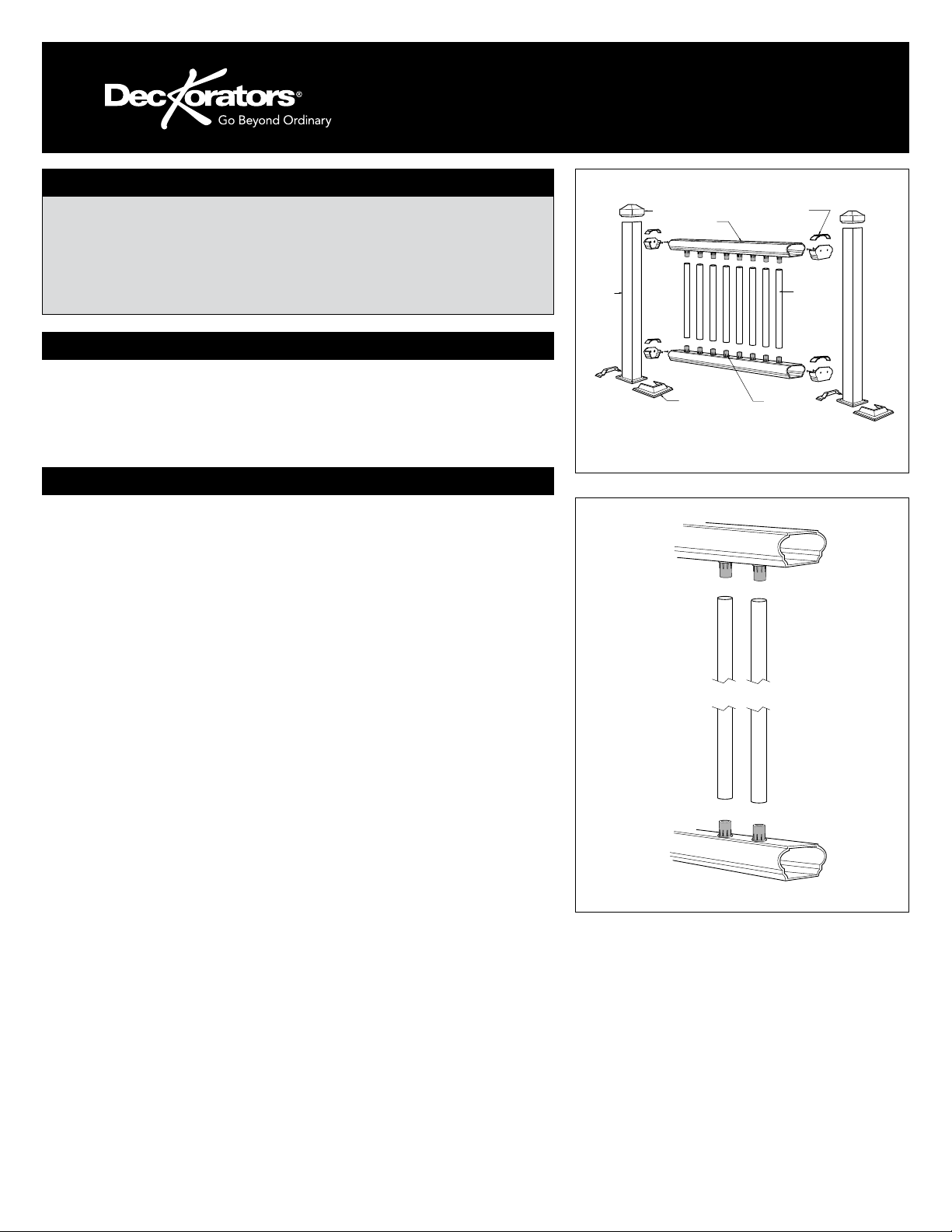
Contents
• Tape measure
Post
Post
Cap
ALX Classic
Rail
Post
Base Trim
In-line
Bracket
Baluster
Baluster
Connectors
fig. 1
fig. 2
Page 2
of the top and bottom rails (fig. 1). Lay bottom rail on deck. The distance
between the post and the first baluster should be less than 4" and equal on both
ends. Mark the angle and length. Repeat with the top rail. Remove an additional
1/4" on both ends (1/2" overall) for the bracket to fit between the rail and post.
Trim the top and bottom rails to length.
Step 8 Position the bottom rail between posts and center. Check building code
requirements for maximum spacing between deck surface and bottom of rail
(sweep). Spacing of 3" is recommended, but can be more or less if codes allow.
Mark the location of the bracket on both posts. Remove rail. Mark the screw
locations and predrill through the posts only, using a 9/64" drill bit.
Step 9 Mark the screw location of bracket on bottom rail. Remove bracket.
Predrill through the bottom of rail only using a 5/32" drill bit.
Step 10 Attach each bracket to the posts with two 3/4" screws.
Step 11 A support block is needed at the center of each 6 ft rail section, 2
support blocks are needed for 8 ft sections. Attach the support block to the
support block connector on the bottom of the lower rail. Mark the location of
the support block on the deck surface and attach the other support block
connector to the deck using the included screw.
Step 12 Install the bottom rail between the posts by setting it in the brackets.
Snap top trim piece to the rail bracket. To secure bottom rail to brackets, push
1/8" Christmas tree fasteners through bracket into the rail.
Step 13 Attach baluster to the lower rail by sliding onto connection (fig. 2).
Step 14 Position the top rail between the posts. Check for level end-to-end
and vertically. Mark the bracket location on post and remove rail. Mark the
screw locations using the bracket as a guide, and predrill using a 1/4" drill bit.
Attach bracket to the post with two 3/4" screws at one end. Repeat for the
other end.
Step 15 Lower the top rail into position, placing the balusters onto the
connectors while working from one end of the railing to the other. Tap with a
rubber mallet if needed to eliminate any gaps. Attach the rail to each bracket by
predrilling with a number 2 drill bit and using two 3/4" screws. Tip: Use a driver
extension bit to avoid marring the rail with the drill chuck.
Step 16 Set post caps on each post. Gently tap with rubber mallet till secure.
Post
Base
Trim
Post
Base
Trim
Post
Cap
Baluster
Connector
Post
•
Cap
Post
•
Sleeve
Top and
Bottom Rail
•
•
Mark Rail
for Length
and Angle
Post
Sleeve
•
•
•
•
Distance
Between
Posts
Mark Rail for
Length and Angle
•
fig. 3
Equal spacing on
both ends
Top Rail
•
•
•
•
Bottom Rail
•
Stair Adaptor
Support
Block
•
•
•
•
•
•
•
6" Maximum
Top Rail Bracket
and Bracket Cover
Post
•
Sleeve
Baluster
Bottom Rail Bracket
and Bracket Cover
•
fig. 4
Stair Railing Installation Instructions
Step 1 Begin by determining where the top and bottom post will be located.
Mark the desired location of the post. Note: To ensure post location is
compatible with railing, prior to securing to the deck, place both posts in
position, and lay the bottom rail along the stair nosing from top to bottom
adjacent to both posts. On the rail side of the post, measure up from the top
of the rail and ensure there is a minimum of 34" to the top of the post. Post
location may need to be adjusted to ensure minimum is obtained. Repeat this
step for the bottom post. For a wood deck, position the post so the fasteners
will go into the floor joists, and make sure the decking is firmly attached to
the joists at the location of the posts. If necessary, use wood blocking as
reinforcement underneath the decking where the posts are located. Fasteners
which hold the post base to the surface should be able to secure to joist or
reinforcement braces, not just the decking itself.
Step 2 F o ur 11/32" diameter mounting holes are provided on the base. When
final position is determined, mark hole locations and remove the post assembly.
Drill the marked locations into decking and reinforcement braces.
Step 3 Reposition the post assembly over predrilled holes. Insert fasteners (not
provided), then secure the base to the deck structure. Make certain the posts
are plumb. If the post requires adjustment, add stainless steel washers under the
base plate.
Step 4 Finish by sliding a post base trim (optional) over each post sleeve for a
finished look. Note: Installing the post base trim prior to installing the bottom rail is
Page 3

recommended. However, the two-piece design does allow the installer to add the
post base trim after the rail has been installed. To install, apply a thin line of clear
exterior construction adhesive to the inside of the post trim where it will contact
the post sleeve and snap into place around the base of the post sleeve.
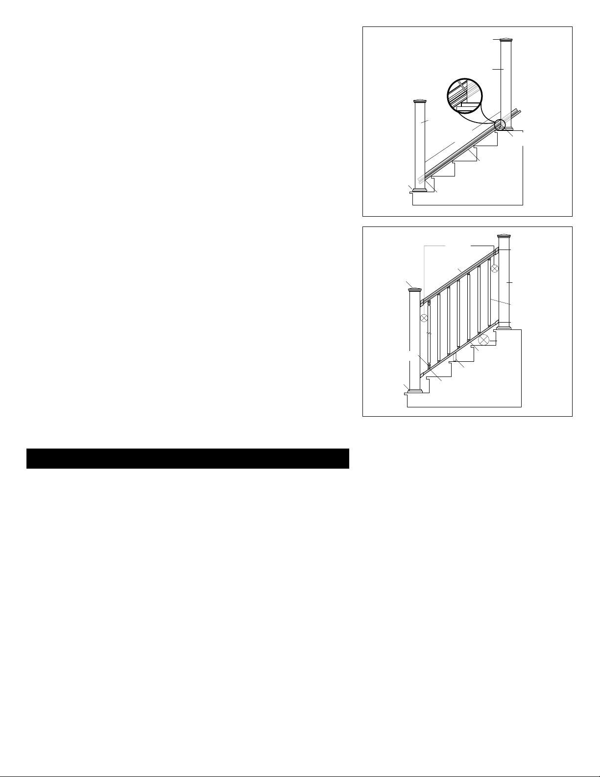
Step 5 Measure the distance between installed posts to determine the length
of the top and bottom rails. Lay bottom rail on stairs with the predrilled holes
facing down. The distance between the post and the first baluster should be
less than 4" and equal on both ends. Mark the angle and length. Do the same
with the top rail. Remove an additional 1/4" on both ends (1/2" overall) for the
bracket to fit between the rail and post. Trim the top and bottom rails to length
with the same angle (fig. 3).
Step 6 Determine the spacing of the balusters, 4-1/2" maximum on-center,
and equal spacing for the end spacing. The rails are predrilled with the proper
spacing. Use a number 2 drill bit to open up the predrilled holes to the angle of
the stairs. The top and bottom connectors will be facing opposite directions.
Attach baluster connectors to rails. Do not over-tighten screws. Apply silicone
caulk on each connector to prevent balusters from turning or rattling after
installation is complete. The caulk should be on the outside of the round
connector and on the inside of the baluster connectors.
Step 7 Position the bottom rail between posts and center. Check building code
requirements for maximum spacing on a staircase, typically less than 6". A 6"
ball cannot pass through the triangle formed by the bottom rail, tread and riser
(fig. 4). Mark the location of the bracket on both posts. Remove rail. Mark the
screw locations and predrill through the post only using a number 2 drill bit.
Step 8 Mark location of bracket on bottom rails. Remove bracket. Predrill
through the rail only, using a 5/32" drill bit.
Step 9 Attach each bracket to the post with two 1-3/4" screws.
Step 10 A support block is needed at the center of each rail. Attach support
block connector to the bottom of the lower rail by finding the center of the
rail and predrill using a number 2 drill bit. Attach the support block connector
using the included screw. Mark the location of the support block on the step
tread and attach the other support block connector to the step tread using the
included screw.
Step 11 Install the bottom rail between the posts by setting rail in brackets.
Snap top trim piece to the rail bracket. To secure bottom rail to brackets, predrill
with a number 2 drill bit and secure using two 3/4" screws. Tip: Use a driver
extension bit to avoid marring the rail or post with the drill chuck.
Step 12 Attach balusters to the lower rail by sliding onto the connectors.
Step 13 Position the top rail between the posts. Check for plumb end-to-end
and vertically. Mark the bracket location on post and remove rail. Mark the
screw locations using the bracket as a guide, and predrill using a number 2 drill
bit. Attach a bracket to the post with two 1-3/4” screws at one end. Repeat for
the other end. Lower the top rail into position, placing the balusters onto the
stair connectors while working from one end of the railing to the other. Tap with
a rubber mallet if needed to eliminate any gaps. Attach the rail to each bracket
by predrilling with a number 2 drill bit and using two 3/4” screws. Tip: Use a
driver extension bit to avoid marring the rail or post with the drill chuck.
Step 14 Set post caps on each post. Gently tap with rubber mallet to secure.
THE DIAGRAMS AND INSTRUCTIONS IN THIS BROCHURE ARE FOR ILLUSTRATION PURPOSES ONLY AND ARE NOT MEANT TO REPLACE A LICENSED PROFESSIONAL. ANY CONSTRUCTION OR USE
OF THE PRODUCT MUST BE IN ACCORDANCE WITH ALL LOCAL ZONING AND/OR BUILDING CODES. THE CONSUMER ASSUMES ALL RISKS AND LIABILITY ASSOCIATED WITH THE CONSTRUCTION
OR USE OF THIS PRODUCT. THE CONSUMER OR CONTRACTOR SHOULD TAKE ALL NECESSARY STEPS TO ENSURE THE SAFETY OF EVERYONE INVOLVED IN THE PROJECT, INCLUDING, BUT NOT
LIMITED TO, WEARING THE APPROPRIATE SAFETY EQUIPMENT. EXCEPT AS CONTAINED IN THE WRITTEN LIMITED WARRANTY, THE WARR ANTOR DOES NOT PROVIDE ANY OTHER WARRANT Y,
EITHER EXPRESS OR IMPLIED, AND SHALL NOT BE LIABLE FOR ANY DAMAGES, INCLUDING CONSEQUENTIAL DAMAGES.
©2012-2015 Universal Forest Products. Deckorators is a registered trademark of Universal Consumer Products, Inc. in the U.S. All rights reserved.
933 US Route 202 Greene, ME 04236-3466
8178 11/15
www.deckorators.com
Page 4

ALX CLASSIC INSTRUCTIONS
D’INSTALLATION
Outils et articles nécessaires
• Tournevis électrique/
perceuse
• Scie circulaire ou à
onglets avec lame à
pointe au carbure
• Équerre marquée
2 - Traverses en aluminium de 6 pi ou 8 pi avec raccords de balustres installés
4 - Supports en ligne
16 - Vis n°8 x 3/4 po
4 - Vis d’arbre de Noël
15 - (noir satin, noir mat ou blanc texturé) balustres classique ou balustres domaine pour
section de 1,8 m (6 pi) (20 balustres pour section de 2,4 m (8 pi) de traverse)
Instructions d’installation pour le garde-corps droit
Avant la construction, consultez l’agence réglementaire locale pour
toutes exigences spéciales du code dans votre région. La hauteur courante
du garde-corps est de 36 po ou 42 po.
Lire toutes les instructions pour bien comprendre comment assembler le
produit et voir comment chaque pièce affecte les autres.
Étape 1 Déterminez le nombre de poteaux de garde-corps nécessaires pour
votre terrasse. Leur espacement devrait être de 1,8 ou 2,4 m (6 ou 8 pi) centre
à centre. Exemple : Une terrasse de 12x16 attachée à un édifice avec une
ouverture d’accès de 4 pi d’un côté exigera en tout huit poteaux.
Étape 2 Installez les manchons de poteau : Installez les poteaux en
attachant la base en aluminium à la surface de la terrasse. Placez le poteau
afin que l’attache entre dans la solive du sol, et vérifiez que la terrasse est
fermement attachée à la solive à l’emplacement des poteaux. Au besoin,
utilisez des blocs de bois comme renforcement en dessous de la terrasse
à l’emplacement des poteaux. Les attaches qui maintiennent la base
du poteau à la surface devraient être en mesure de fixer la solive ou les
entretoises de renforcement, en plus de fixer la terrasse. Remarque : Lors
de l’installation du poteau en aluminium en haut d’une surface en bois, les
vis doivent être insérées à une profondeur d’au moins 3 po du bois solide.
Les planches de terrasse de 5/4 po ou 1 ½ po ne fournissent pas de matériel
suffisant pour une installation sécuritaire. Au besoin, ajoutez du matériel
supplémentaire sous la surface.
Étape 3 Placez le poteau à l’endroit où il sera attaché à la terrasse. Quatre
trous de montage d’un diamètre de 11/32 po sont fournis sur la base. Lorsque
l’emplacement final a été déterminé, marquez les emplacements. Enlevez le
poteau et percez des trous de 15/64 po aux emplacements marqués dans la
terrasse et le renforcement.
Étape 4 Replacez le poteau au-dessus des trous pré-percés et insérez les
attaches (non incluses). Attaches recommandées : 4 – vis tire-fond en acier
inoxydable de 5/16 po x 4 po ou plus longues.
Étape 5 Finissez en glissant une garniture de base de poteau (facultative)
sur chaque manchon de poteau pour offrir un beau fini. Remarque : Il est
recommandé d’installer la garniture de base de poteau avant la traverse
inférieure. Cependant, la conception à deux pièces permet à l’installateur
• Niveau de menuisier
• Crayon de menuisier
• Clé ajustable ou clé
à douille pour les
boulons, etc.
• Lunettes de sécurité
Contents
• Maillet de caoutchouc
• Ruban à mesurer
Poteau
Capuchon
de poteau
Traverse Classic
ALX
Garniture de
base de poteau
Support de ligne droite
Balustre
Raccords
de balustres
fig. 1
fig. 2
 Loading...