

Decko 24000-DKO Owner's Manual

For Use With Residential Sectional Garage Doors Only
www.deckogdo.com
1-877-GDO-4402
1-877-436-4402
● Please read and understand this manual and safety instructions carefully before installation.
● The Opener WILL NOT CLOSE until the Photo Eye Safety System is properly installed and aligned.
● REGULARLY CHECK and TEST the Opener according to the safety label to ENSURE SAFE OPERATION.
● Retain this manual for future reference.
Serial # __ __ __ __ __ __ __ Date Installed __ __ /__ __ /__ __ __ __
GDO Manual Revised: 05-10
GARAGE DOOR OPENER
MODEL: 24000-DKO
HANDLES DOORS 18 FT. WIDE & UP TO 7FT.TALL
Owner’s Manual

Table of Contents
Courtesy light turns on/flashes with audible ‘click’.
(If light bulb is not installed, ‘click’ represents the light)
DO NOT connect power
Please connect power
Introduction
Symbols and Icons 2
Inventory 3
Preparation / Door Balance Test 4
Tools Required 4
Assembly
Rail and Trolley Assembly 5
Installing the Cable and Chain 6
Mounting Header Bracket 7
Installation
Attaching the Opener Assembly to Header Bracket 8
Mounting Door Bracket 8
Mounting Opener to Ceiling 9
Attaching Door Arms 10
Installing Light and Emergency Release Handle 11
Wiring
Wiring Instructions 12
Connecting Photo Eye Safety System 13
Connecting Wall Panel 14
Connecting Power 15
Adjustment
Aligning the Photo Eye Safety System 15
Travel Limit Adjustment 16
Force Adjustment 17
Final Adjustment and Testing 18
Operation
Programming Hand-held Transmitter 19
Operating the Opener 20-21
Maintenance 22
Troubleshooting 22
Repair Parts and Service
Installation and Accessory Parts 23
Opener Assembly parts 24
Warranty 25
Symbols and Icons
!
WARNING
READ WARNINGS CAREFULLY to prevent SERIOUS INJURY or DEATH caused by
electrocution or mechanical hazard.
2
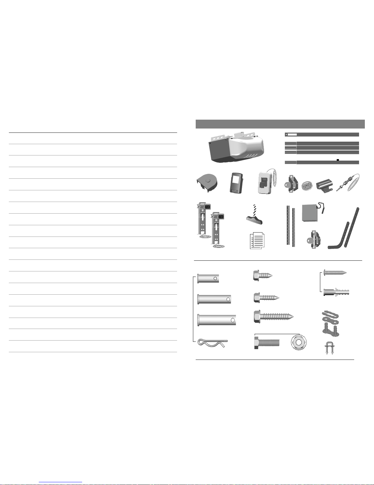
Installation hardware
NOTES
NOTES
3
— Door arms / Mounting Opener
Inventory
x 2
Clevis Pin — Pulley
3/8” x 1-3/4”
Hitch Pin — Locking Clevis Pins
x 4
Lag Screw #12 x 1”— Photo Eye System
Lag Screw 5/16” x 1-1/2”
— Header Bracket / Mounting Opener
Bolt 5/16” x 1”
Drywall Anchor - Wall Panel
x 2
x 2
Screw #6 x 1” - Wall Panel
x 30
5/16” Flange Nut
x 4
x 4
x 4
x 4
x 1
x 1
Emergency Release Knob + Rope
Literature + Safety Labels
Chain
Photo Eye Safety System
Opener Unit + Lamp Dome
Sprocket Cover
Single-Button
Transmitter
Wall Panel
Header
Bracket
Door Bracket
Trolley
Door Arms
Pulley
Rail — Header Segment
Rail — Middle Segments x3
INSTALLATION HARDWARE, LOCATED IN HARDWARE BAG (SHOWN IN ACTUAL SIZE)
Hanging
Brackets
Insulated Staples
— Securing wires
x 2
Self-Threading Screw 1/4” x 5/8”
Door Bracket
Trolley Shaft
and Cable
Master Link Set
—Trolley Shaft
x 1
Rail — End Segment with Trolley Stop Bolt
Clevis Pin — Door arms
5/16” x 1”
Clevis Pin — Header Bracket
5/16” x 1-1/2”
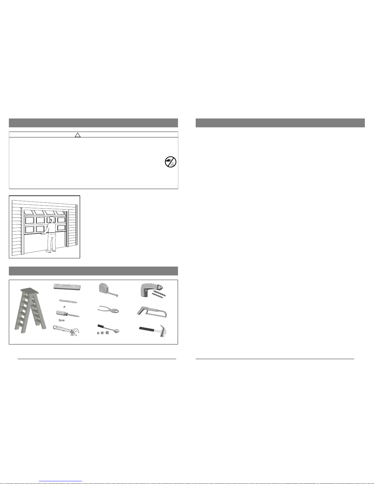
Preparation
Level
Tape Measure
Hack Saw
Pencil
Drill, 3/16” and 5/16” Drill Bits
Tools Required
Step Ladder
Screwdriver
Hammer
Sectional Garage Door
BEFORE Beginning Installation:
1. Disable locks and remove all ropes connected to the
garage door.
2. Perform the following door test to ensure your door is
balanced and in good working condition.
To Test Your Garage Door
1. Raise and lower the door to check if t here is any sticking or
binding.
2. Check for loose hinges, damaged rollers, frayed cables and
damaged or broken springs.
3. Lift the door approximately halfway and release. The door
should stay at the point under proper spring tension.
Call a qualified garage door service technician if your door binds,
sticks or is unbalanced.
!
WARNING
To prevent SERIOUS INJURY or DEATH:
- Before beginning installation of the Opener please complete the f ollowing test to ensure that your door is
balanced and in good working condition.
- A poorly balanced door can cause serious injury and damage to the Opener.
- Always hav e a qualified garage door service technician make any required adjustments and/or repairs to
your door before proceeding with installation.
- DISABLE ALL LOCKS and REMOVE ALL ROPES connected to the garage door BEFORE installing
and/or operating the Opener.
To prevent damage to the door and Opener:
- DO NOT connect power until instructed.
- Operate this Opener with AC 120V/60Hz power supply ONLY.
Pliers
Adjustable Wrench
4
Ratchet with
5/16”, 7/16” and 1/2” sockets
Warranty
LIMITED WARRANTY AND LIMITATION OF LIABILITY
Decko Products warrants, to the first purchaser of this product, for the initial residence
in which it is installed, to be free from defects in materials and or workmanship for a
period of 1 YEAR from date of purchase and that the motor to be free from defects in
materials and or workmanship for a period of 6 YEARS from date of purchase. As the
sole and exclusive remedy for a breach of this limited warranty, if the product is found
by Decko Products to be defective, Decko Products, at its option, will repair or replace
the product with an equivalent product if it is returned to the place of purchase or
returned with proof of purchase post paid to
Decko Products,
ATTN: Warranty Dept.,
2301 Traffic St. NE
Minneapolis, MN 55413
ANY DISASSEMBLY, MODIFICATION, OR ABUSE OF THIS PRODUCT VOIDS
THIS LIMITED WARRANTY.
DECKO DISCLAIMS ALL OTHER EXPRESS OR IMPLIED WARRANTIES,
INCLUDING WARRANTIES OF MERCHANTABILITY OR FITNESS FOR A
PARTICULAR PURPOSE.
THIS LIMITED WARRANTY DOES NOT COVER ANY PROBLEMS WITH OR
RELATED TO THE GARAGE DOOR OR GARAGE DOOR HARDWARE. THIS
INCLUDES BUT IS NOT LIMITED TO THE DOOR SPRINGS, DOOR ROLLERS,
DOOR ALIGNMENT OR DOOR HINGES.
DECKO PRODUCTS SHALL NOT BE LIABLE FOR CONSEQUENTIAL OR
INCIDENTAL DAMAGES THAT ARISE IN CONNECTION WITH USE, OR INABILITY TO USE THIS PRODUCT.
Some states do not allow the exclusion or limitation of consequential or incidental damages, so the
above limitation or exclusion may not apply to you. This limited warranty gives you specific legal
rights, and you may also have other rights which vary from state to state.
25
Part No. Name / Description Item
24935 Sprocket Cover 1
*
Sprocket and gear assembly 2
*
Chassis 3
*
Lamp plate 4
24905 Lamp Dome 5
*
Capacitor 6
*
Capacitor holder 7
8
*
Motor assembly
9
*
RPM wheel
10
*
Logic Board holder
11
*
Logic Board
12
*
Limit system driving gear
13
*
Limit system assembly
14 24937 Opener cover
Green
Screw
Gear
Close limit Contact
Open limit Contact
Center limit Contact
Red
Screw
Orange
Blue
Green
Limit System Assembly
1
2
3
4
5
6
7
8
9
11
10
12
13
14
Opener Assembly Parts
* Should be replaced by qualified technician only
24
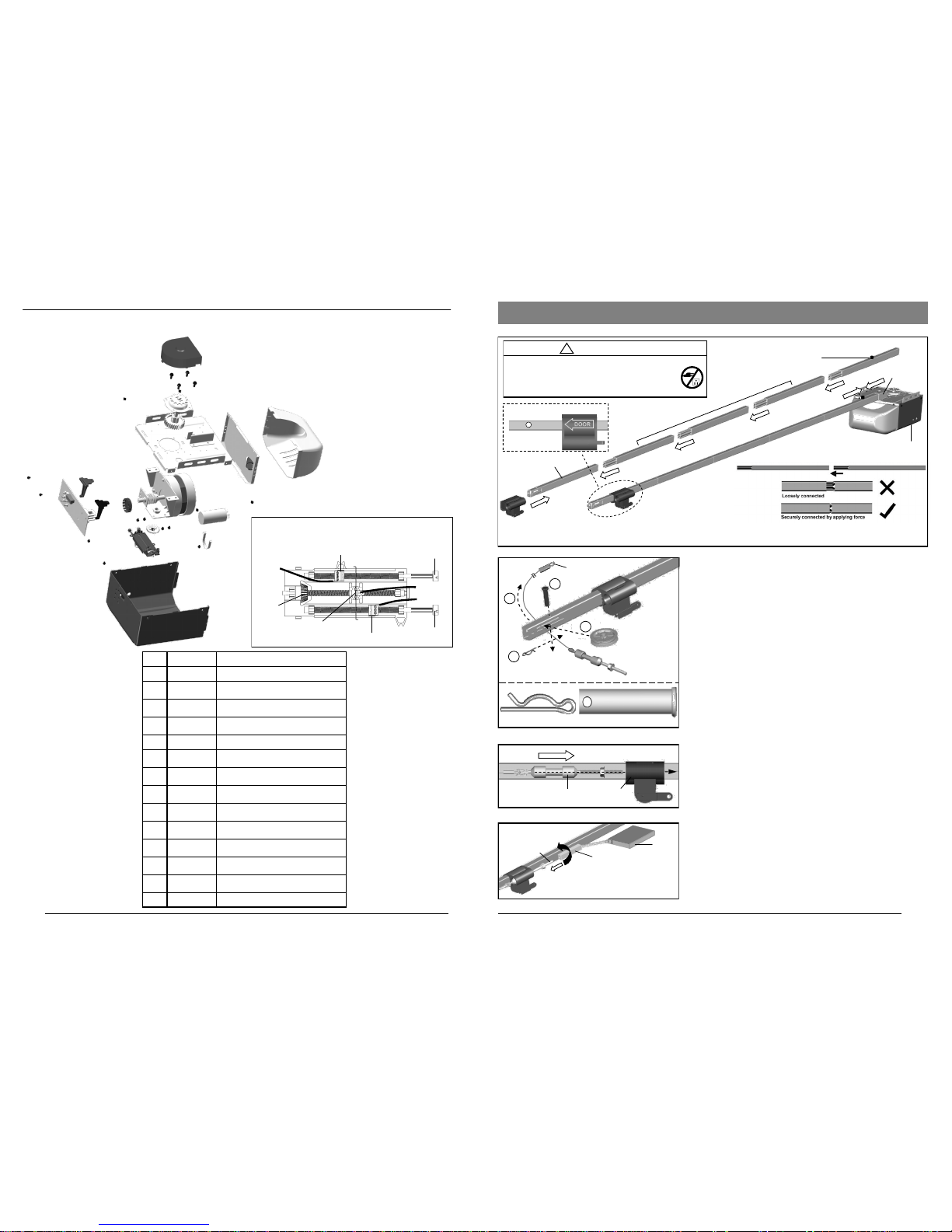
Rail and Trolley Assembly
Opener
Trolley direction (Top View)
Clevis Pin
Pulley
Hitch Pin
Clevis Pin — 3/8” x 1-3/4”
Hitch Pin
Connect shaft to Trolley with “click”
To Assemble Rail and Opener
1. Prepare the rails as shown in Fig.1.
2. Connect the rails starting with t he Header Segment. Insert
the tapered ends into open ends, apply any additional f orce
necessary by tapping the Rail on padded f looring. Ensure
the End Segment has Trolley Stop Bolt facing up. Make
sure the rails are securely joined together as shown.
3. Slide the Trolley onto the rail f rom the Header Segment.
Make sure the arrow is pointing towards the door as shown
in Fig.1.
4. Connect the rail assembly to the Rail Bracket on the Open-
er.
To Assemble the Header Section of Rail
Follow steps shown in Fig.2:
1. Remove the “Trolley Shaft and Cable” from the Chain carton
and lay it beside the rail assembly. Hold Cable Eyelet on the
end of cable and thread about 20” (50cm) through the slot
on the Header Segment of the rail.
2. Insert the Pulley into the opening while the cable is hanging.
3. Secure the Pulley by inserting the 3/8” x 1-3/4” Clevis Pin
through the top of the rail.
4. Lock the Clevis Pin with a Hitch Pin. Rotate the Pulley to
ensure it spins smoothly.
Refer to Fig.3 to connect the Trolley Shaft to the T rolley. Slide
both the Trolley Shaft and Trolley towards each other. A “click”
will be heard when they are connected.
To Link Cable with Chain
Refer to Fig.4. Place the chain carton beside the rail, hold the
“Chain to Cable Connector” and pull about 8” (20cm) of chain
from the box. Thread the Chain to Cable Connector onto the
Trolley Shaft so that they are loosely linked together.
Fig.1
Fig.2
Fig.4
Fig.3
!
CAUTION
- DO NOT connect power until instructed.
- To prevent INJURY, keep hands and fingers
away from joints and possible sharp edges.
- Wear gloves when installing chain and cable.
Rail Bracket
1
3
4
2
Trolley Shaft
Trolley Shaft T rolley
Cable Eyelet
Loosely link together
Trolley Shaft
Chain-to-Cable Connector
Chain
5
When connecting the rails ensure they are securely connected as shown above.
To apply additional force tap gently on the end of the rail with a rubber mallet*.
*Only use a soft rubber mallet to tap on the end of the rails as other tools may damage your rail.
Rail — Header Segment
Rail — Middle Segments
(tapered) x 3
Rail — End Segment (tapered)
with Trolley Stop Bolt
 Loading...