

Deckma Hamburg OMD-2008 Instruction Manual
INSTRUCTION MANUAL
15ppm Bilge Alarm
OMD-2008
Versions with
Electric Valve (EV)
Flow Control (FC)
Manual Cleaning Unit (MCU)
DECKMA HAMBURG GmbH
Kieler Straße 316, D-22525 Hamburg - Germany
Tel.: +49 (0) 40 54 88 76-0, Fax: +49 (0) 40 54 88 76-10
Internet: www.deckma.com eMail: post@deckma.com
MOTEC
Marine & Offshore Technology

DECKMA HAMBURG GmbH
Issue: 08.07.2015 Instruction Manual OMD-2008 (EV, FC, MCU Versions) Page 1 of 28
IMPORTANT NOTICE
Replacement components for 15ppm Bilge Alarms.
General
All monitors in our range are inspected and tested to the related I.M.O. requirements at
our factories prior to delivery.
In normal use the units should operate correctly and without fault over a long period of
time requiring only small amounts of maintenance to be carried out as outlined in the
instruction manuals.
Service Exchange Units
In the event of a monitor malfunction due to electrical or electronic component failure it
is our recommendation that a service exchange unit be ordered.
The defective instrument should be returned to our works within 30 days of supplying
the service exchange unit, then only the repair charge is payable. Otherwise the whole
cost of a service exchange unit becomes payable.
This procedure is by far the easiest and most cost effective way of ensuring the monitor
on board conforms to I.M.O. resolution MEPC.107(49).
Remark:
According the MEPC.107(49) § 4.2.11 the unit has to be checked at IOPP Certificate
renewal survey by the manufacturer or persons authorized by the manufacturer.
Alternatively the unit may be replaced by a calibrated 15 ppm Bilge Alarm.
The OMD-2008 EVFC is designed in that way, that only the measuring cell needs to be
changed, as this unit carries the Calibration Certificate. The Calibration Certificate with
the date of the last calibration check should be retained onboard for inspection
purposes.
If for some reasons the computer unit needs to be changed, it has to make sure, that
the memory card will remain on board for at least 18 month. The new computer unit will
carry its own memory card. The old card can be insert into the new unit only for reading.
Writing is only possible with the card delivered with the new computer unit. For details
see section 13.1.
Warranty
Our warranty terms are12 months after installation but maximum 18 months after
delivery ex works. The maker undertakes to remedy any defect resulting from faulty
materials of workmanship except wearing parts.
The maker's obligation is limited to the repairs or replacement of such defective parts by
his own plant or one of his authorized service stations.
The purchaser shall bear the cost and risk of transport of defective parts and repaired
parts supplied in replacement of such defective parts.
ANY DISMANTLING OR BREAKING OF A SEAL WILL VOID THE WARRANTY

DECKMA HAMBURG GmbH
Issue: 08.07.2015 Instruction Manual OMD-2008 (EV, FC, MCU Versions) Page 2 of 28
SECTION
TITLE
PAGE
1
Introduction
3
2
Important Notes
3
3
Principle of Operation
4
3.1
Measuring Principle
4
3.2
Features
4
3.3
Adjustment
4
3.4
Displays and Alarms
4
3.5
FC (Flow Control)
5
3.6
EV (Electric clean water Valve)
5
3.7
MCU (Manual Cleaning Unit)
5
4
Specification
6
5
Construction
7
6
Installation
8
7
Piping
10
8
Wiring
11
8.1
Typical Control System
13
9
Power Supply
13
10
Commissioning
14
10.1
Electrical and Piping
14
10.2
Flow Rate Adjustment
14
10.3
Functional Tests
15
10.4
Programming Mode
16
11
Operating Instructions
20
11.1
Operator Notes
20
12
Operator Maintenance
22
12.1
Manual Cell Clean Unit
21
Important Information: Cleaning of Glass Tube
23
13
Fault Finding
24
13.1
Memory Card
25
14
Calibration
25
14.1
Calibration and Repeatability Check
26
14.2
Function Test at Classification Survey
and Port State Control
26
15
Spare Parts
27
15.1
Recommended On Board Spares
27
16
Remarks
28

DECKMA HAMBURG GmbH
Issue: 08.07.2015 Instruction Manual OMD-2008 (EV, FC, MCU Versions) Page 3 of 28
1 Introduction
The OMD-2008 EV-FC Bilge Alarm Unit has been designed specifically for use in
conjunction with 15 ppm oil-water separator units and has a specification and
performance which exceeds the requirements of the International Maritime
Organization specifications for 15ppm Bilge Alarms contained in Resolution
MEPC. 107 (49).
The unit is supplied with 2 works-adjusted alarms at 15 ppm. Other set points
(10 ppm or 5 ppm) are possible and can be adjusted on site at any time by using
the buttons at the front panel.
Instruments with maximum Alarm set-points of 10 ppm or 5 ppm respectively are
available.
If an alarm set point is exceed, the alarms are visible at the front panel and the
appropriate relays are switched. In case of malfunction the System LED at the
front panel will change from blinking green to permanent red.
For the data logging function the unit requires a status input from the separator.
A 0(4) - 20 mA (equal to 0 - 30 ppm) signal output is available for driving a
recorder or external meter.
The OMD-2008 EV-FC is be equipped with an electric switchover valve for clean
water usage and a Flow Sensor. A Manual Cleaning Unit is available as an
option (MCU). Different instrument versions are covered in this document. Please
verify instrument version on site and refer to the relevant sections of this manual.
2 Important Notes
a) This equipment must be installed and operated in strict accordance with the
instructions contained in this manual. Failure to do so will impair the protection
provided.
b) Installation and servicing must be undertaken by a competent and suitable
skilled person.
c) The equipment must be connected to the ground according relevant
requirements.
d) The unit must be isolated from the electrical supply before any maintenance of
the equipment is attempted.
e) All National or local codes of practice or regulations must be observed and,
where applicable, are deemed to take precedence over any directive or
information contained in this manual.
f) In case of freezing conditions the measuring cell should be emptied
completely.

DECKMA HAMBURG GmbH
Issue: 08.07.2015 Instruction Manual OMD-2008 (EV, FC, MCU Versions) Page 4 of 28
3 Principle of operation
3.1 Measuring Principle
An optical sensor array measures a combination of light scattered and absorbed
by oil droplets in the sample stream. The sensor signals are processed by a
microprocessor to produce linearized output.
If an alarm (works set point 15 ppm, or 10 ppm or 5 ppm respectively) occurs, the
two oil alarm relays are activated after the adjusted time delay.
The microprocessor continuously monitors the condition of the sensor
components and associated electronics to ensure that calibration accuracy is
maintained over time and extremes of environmental conditions.
3.2 Features
Robust construction
Solid suppression capability
Low maintenance
Easy installation
Constant readiness
Low spare part stock holding
Works adjustment
Easy settings via menu
3.3 Adjustment
The unit is delivered with a works calibration according the IMO-requirements.
The alarm points are set to 15 ppm (or 10 ppm, or 5 ppm for certain versions).
The "Zero" point is also works calibrated and can be re-adjusted on site by using
the programming mode and clean water. See Section 10.4 “Settings-Offset”. A
calibration is not permitted. This has to be done according IMO Regulations by
the manufacturer or persons authorized by the manufacturer.
3.4 Displays and Alarms
In the unit there are two independent oil alarm circuits available. Both can be set
separately from 1 to 15 ppm. From the manufacturing both alarms are set to
15 ppm (according IMO). The set points can be changed according to the
requirements on site, for example to 10 ppm or 5 ppm. An alarm point setting
above 15 ppm is not possible. The adjustment can be done in the programming
mode as described in Section 10.4.

DECKMA HAMBURG GmbH
Issue: 08.07.2015 Instruction Manual OMD-2008 (EV, FC, MCU Versions) Page 5 of 28
In this mode also the individual adjustment of the time delays for the alarms can
be done.
Both alarm circuits are also related to an alarm LED on the front panel.
In case of malfunction the “System” LED will indicate any type of internal fault of
the unit. This LED is flashing green in normal conditions and is red in alarm
conditions.
Additional to the alarm LEDs each alarm circuit is equipped with a relay with
potential free alarm contacts. These contacts can be used for external processing
of the signal or for control of further functions.
If a malfunction or failure of the power supply occurs, all three relays (both alarm
relays and the SYSTEMFAULT relay) will switch to alarm condition.
3.5 FC (Flow Control)
OMD-2008 EV-FC instruments are equipped with a Flow Sensor. The Flow
Sensor is connected in the Drain line of the Measuring Cell. If the flow rate
through the Measuring Cell is too low, or if the sample is not flowing at all, the
Instrument will go to Alarm condition and issue a “Status: Flow?” message.
3.6 EV (Electric clean water Valve)
OMD-2008 EV instruments are equipped with an electric switchover valve for the
clean water stream. The valve can be controlled via the menues, or remotely
using the control input.
3.7 MCU (Manual Cleaning Unit)
Optionally the instruments can be fitted with a Manual Cleaning Unit. The Manual
Cleaning Unit allows to clean the sample glass tube without opening the
Measuring Cell Head Screw, and without interrupting the normal sample flow.
Maintenance is made easier with the MCU. Please note that operating the MCU
may set the instrument to alarm condition for a few seconds.

DECKMA HAMBURG GmbH
Issue: 08.07.2015 Instruction Manual OMD-2008 (EV, FC, MCU Versions) Page 6 of 28
4 Specification OMD-2008 EV FC
Range:
0 – 30 ppm, Trend indication 50ppm
Accuracy
According IMO MEPC. 107(49)
Linearity
Up to 30 ppm better than ± 2 %
Display
Yellow Graphic Display
Power Supply:
24 V - 240V AC or DC
Automatic Voltage selection
Consumption:
< 10 VA
Alarm Points 1 + 2:
Adjustable between 1 - 15 ppm
(Works adjustment 15 ppm)
Alarm 1 Operating Delay:
(for annunciation purpose)
Adjustable between 1 – 540 sec.
(Works adjustment 2 sec)
Alarm 2 Operating Delay:
(for control purposes)
Adjustable between 1 – 10 sec.
(Works adjustment 10 sec)
System Fault Alarm:
Red LED
Alarm Contact Rating:
Potential free 1 pole change over contacts,
3 A / 240 V
Alarm Indication:
Red LEDs
Output Signal:
0 – 20 mA or 4 – 20 selectable
ext. Load < 150
Sample Water Pressure:
0,1 – 10 bar
Sample Flow:
Approx. 0,1 - 3 l/min depending on pressure
Ambient Temperature:
+ 1 to + 55° C
Sample Water Temperature:
+ 1 to + 65° C
Roll:
Up to 45°
Size (Computer Unit)
200 mm W x 200 mm H x 100 mm D
Size (EV-FC-Arrangement)
150 mm W x 290 mm H x 140 mm D
Degree of Protection:
IP 65
Weight:
5,9 kg
Pipe Connections:
for 6mm OD Cu or SS pipe
Technical specifications are subject to change without notification
DECKMA HAMBURG GmbH
Issue: 08.07.2015 Instruction Manual OMD-2008 (EV, FC, MCU Versions) Page 7 of 28
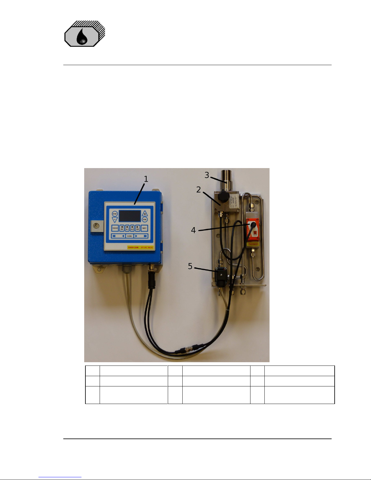
5 Construction
OMD-2008 EV-FC consists of two main components:
The computer unit contains the display PCB with the data logger and the
terminals for external connections.
The measuring cell is built out of an all-aluminium, nickel plated body with inlet
and outlet block from stainless steel. It contains optics and electronics and is
connected with the computer unit via a plugged data cable. It is mounted onto a
stainless steel support that also holds the valve assembly and the Flow Sensor.
An electric valve controls sample water and clean water usage.
The OMD-2008 EV-FC can easily be mounted in wall or bulkhead installation.
1
Computer Unit
4
Flow Sensor
2
Measuring Cell
5
Clean Water Valve EV
3
Manual Cleaning Unit
(MCU) (Option)
Fig. 1
DECKMA HAMBURG GmbH
Issue: 08.07.2015 Instruction Manual OMD-2008 (EV, FC, MCU Versions) Page 8 of 28
6 INSTALLATION (REFER TO FIG. 2 AND FIG. 3)
See Section 2 for important notes concerning installation.
The OMD-2008 EV-FC Monitor should be located as close as possible to the oily
water separator to minimize response delays. According MEPC.107(49) the
layout of the installation should be arranged so that the overall response time
(including the response time of the 15 ppm Bilge Alarm, which is less than 5 s.)
between an effluent discharge from the 15 ppm Bilge Separator exceeding 15
ppm, and the operation of the Automatic Stopping Device preventing overboard
discharge, should be as short as possible and in any case not more than 20 s.
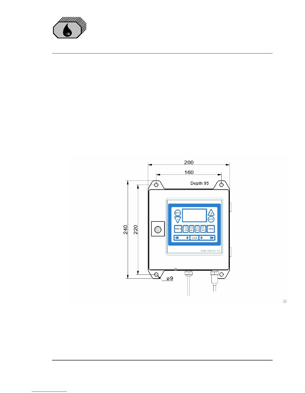
Mount the OMD-2008 EV-FC Computer Unit by means of M6 or M8 screws on to
a rigid vertical surface and preferably with the display panel of the monitor at eye
level. For service and maintenance sufficient space to all sides should be
available.
Fig. 2a: Dimensions of Computer Unit
Computer Unit and Measuring Cell assembly should be mounted close to each
other.
 Loading...