


Installation Instructions Van:
VNNS11NSNV55
NISSAN NV
146.1” WHEELBASE
2012-CURRENT
TOOLS REQUIRED
Adjustable wrench (that opens to about 1”), 1/2” open end wrench, Phillips screwdriver,
3/8” socket, 7/16” socket, 7/32” Allen wrench, 13 mm socket, 10 mm socket (these metric tools
were specified by Nissan)
Watch short installation videos at www.decked.com/video | Register your system at www.decked.com/warranty
follow us:
VERSION 1
DECKED.COM | SERVICE@DECKED.COM | 208.806.0251

This product MUST BE INSTALLED in
This product MUST BE INSTALLED in conjunction with a
conjunction with a bulkhead wall, and/or
bulkhead wall, and/or adequate structural framework
adequate structural framework to prevent
to prevent injury as a result of a traffic accident.
injury as a result of a traffic accident.
MADE IN USA
MADE IN USA
▼ READ BEFORE YOU INSTALL DECKED ▼
DON’T use power tools to assemble or install the DECKED system. Impact wrenches and other power tools
can over tighten and damage components (aside from drilling drain holes in ammo cans).
DON’T over tighten J-hooks during installation. J-hooks need to be snug to keep system from moving
around, but should NOT be cranked down.
DON’T over torque any bolts, particularly the bolts attaching the center vert to the deck halves.
REAR ammo cans have flat bottoms; FRONT ammo cans are narrow at the bottom.
NOTE: You will need a buddy with exactly two steps.
Need Help? Watch our detailed installation video or give us a call. We’re happy to help!
SERVICE@DECKED.COM | 208.806.0251 | DECKED.COM/INSTALLVIDEO
JHOOK
ATTACHMENTS
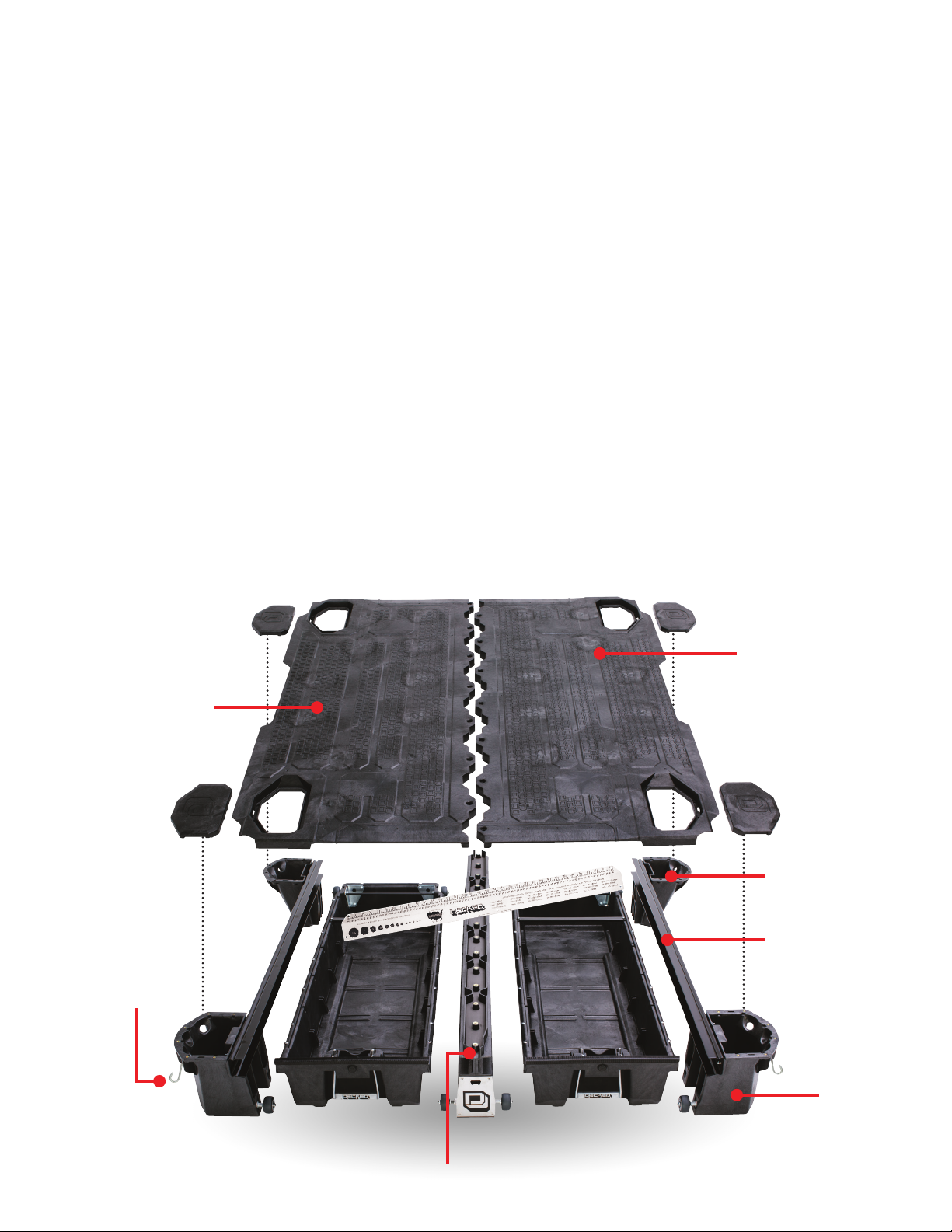
▼ ASSEMBLY OVERVIEW ▼
PASSENGER SIDE
DECK HALF
DRIVER SIDE
DECK HALF
FRONT AMMO CAN
CCHANNEL
CENTER VERT
REAR
AMMO CAN
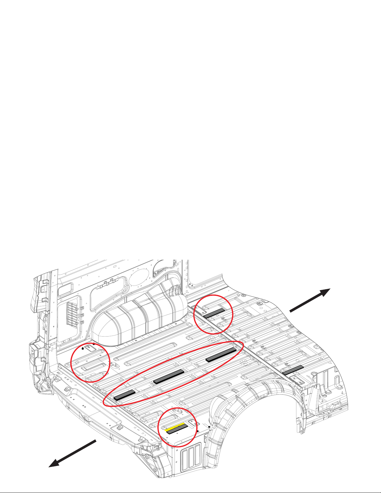
PREPARE VAN: INSTALL SHIMS
There are 3 DOUBLE STACKED shims and 3 SINGLE shims provided:
1) If your vehicle is equipped with a rubber floor mat in the cargo area, you will need to remove the
screws securing the plastic trim pieces at the base of the rear door and side door openings, and
remove and set aside the plastic trim pieces. If no mat is installed, skip to STEP 3 on this page.
2) At the rear door opening, lift the floor mat and fold it forward so it is clear of the floor area where
the shims will be placed.
3) Using the information in the respective circular detail views on the next page:
a) Clean the surfaces where the shims will be located.
b) Remove the layer of tape on the bottom of the shim to expose the adhesive surface.
c) Place the shim and apply with pressure.
NOTE: STEP B is to be repeated on the passenger side.
4) When all shims are placed, roll the rubber mat back to cover the floor.
B
NO
SHIM
A
FRONT
REAR
C
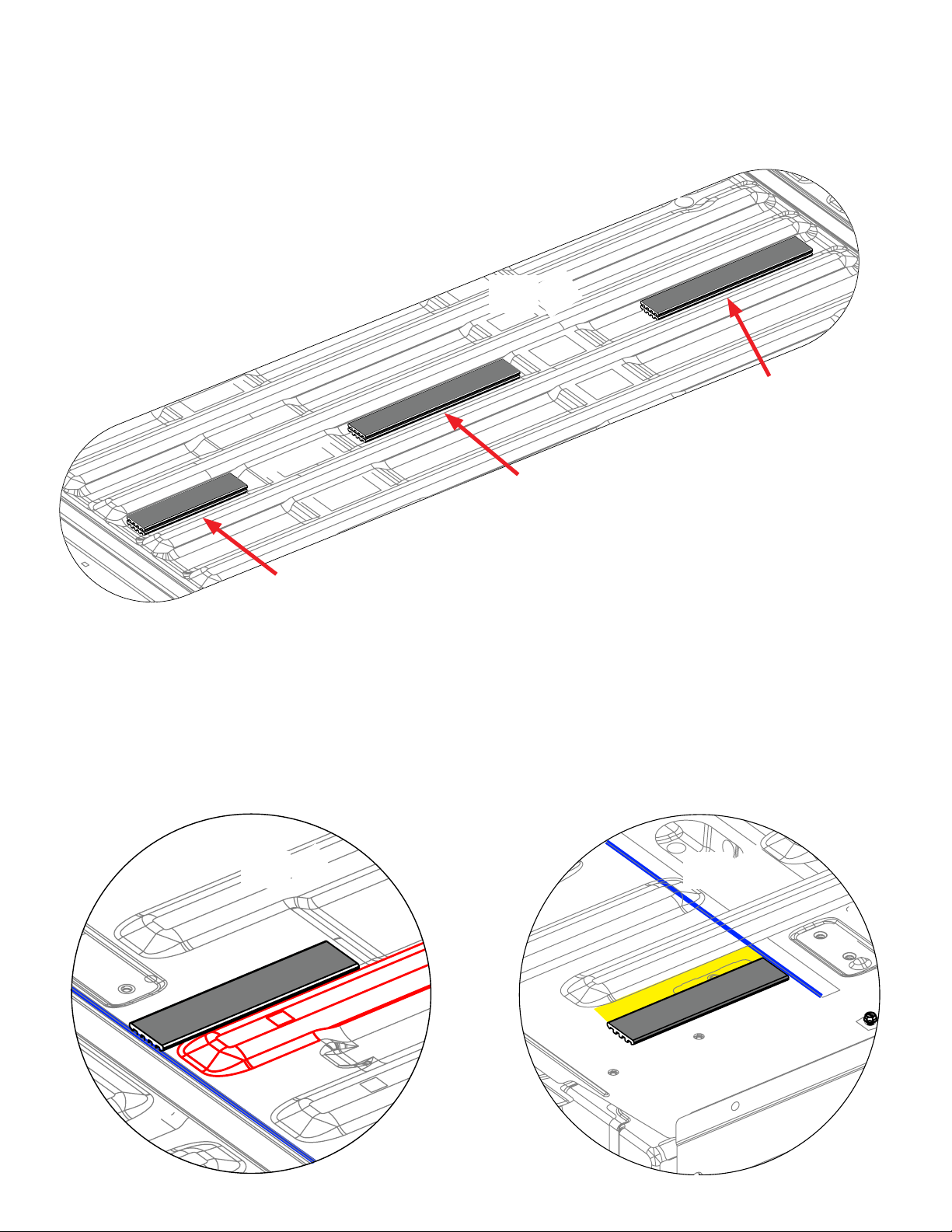
PREPARE VAN: INSTALL SHIMS
DETAILED VIEW
DETAIL A
DOUBLE STACK
DOUBLE STACK
Short double stack
shim at centerline of rib
pocket on rear of van
DETAIL B
Place front end of shim adjacent to floor bead (red).
Align rear of shims adjacent to transverse bead (blue line).
Repeat on passenger side.
FRONT
OF VAN
Long double stack
shim at centerline
of rib pocket
Place front end of shim 1 3/8” from side of bead. Align
DOUBLE STACK
➡
Long double stack
shim at centerline of
front van end rib pocket
DETAIL C
shim with floor bead (blue line)
FRONT
OF VAN
➡
1 3/8”
FRONT
OF VAN
➡
PREPARE VAN: INSTALL TIEDOWN
BRACKETS
1) Follow instructions for each detailed view (next page) to install tie-down brackets.
2) When all brackets are installed, begin to roll rubber floor mat rearward until you encounter front
mounting brackets.
3) Make lateral slit with a razor knife in rubber mat to allow vertical leg of mounting bracket to
protrude through mat.
4) Continue to roll mat towards the rear door until you encounter rear mounting brackets.
5) Make a fore-aft slit in mat to allow vertical leg of mounting bracket to protrude.
6) Finish unrolling rubber mat.
7) Reinstall the plastic side and rear door trim pieces and secure with screws.
B
BRACKETS AND HARDWARE
ARE FOUND IN BAG MARKED
TIE-DOWN BRACKETS
A
FRONT
D
REAR
C

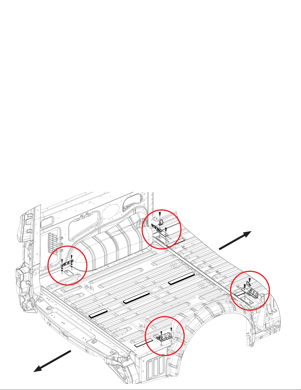
PREPARE VAN: INSTALL TIEDOWN
BRACKETS CONT.
DETAIL B
1) Unbolt and remove factory cargo tie down ring.
2) Cover bolt hole with a piece of duct tape to provide
vapor barrier.
3) Remove 2 factory bolts in floor.
4) Place new tie down bracket, oriented as shown.
5) Install 2 washers under bracket at each bolt location.
6) Fasten with DECKED provided bolts.
FRONT
OF VAN
➡
DETAIL A & D
1) Unbolt and remove factory cargo tie down ring.
2) Place new tie down bracket, oriented as shown
3) Replace cargo tie down ring, oriented as shown
4) Fasten with DECKED provided bolts
DETAIL A
FRONT
OF VAN
➡
DETAIL C
1) Remove factory bolts from floor.
2) Place new tie down bracket, oriented as shown.
3) Fasten with DECKED provided bolts.
OF VAN
FRONT
➡
DETAIL D
FRONT
OF VAN
➡

STEP 1: DRIVER SIDE DECK ASSEMBLY
• Loosely bolt C-channel to the ledges on the inside of the two ammo cans. Make sure bolt head is
on the C-channel side, not inside ammo can; bag 1A. NOTE: The small rectangular slot in the
C-channel indicates the rear end.
• Line up the deck (sticker indicates driver side deck half) on top of the C-channel/ammo can assembly
and the vert bosses. NOTE: Rear side of vert has an axle hole at the bottom (see below).
• Bolt deck to C-channel/ammo can assembly; bag 1B for driver side rear ammo can, bag 1C for driver
side front ammo can.
• Go back and tighten loose bolts connecting ammo cans to C-channel.
• Bolt the deck to the vert; bag 1D. Do not use power tools.
• Grab your buddy to help you lift assembly onto driver side of van.
1D
VERT AXLE HOLE ON REAR END
VERT
CCHANNEL
RECTANGULAR
HOLE IN CCHANNEL
1B
1A
DRIVER SIDE DECK HALF
1C
FRONT
AMMO CAN
REAR
AMMO CAN

STEP 2: INSTALL AXLES
1). Install the driver side rear ammo can axle; bag 2A.
• Rotate the axle from its inbound side using a wrench on the “flat” end. Nut is included in bag
and can be held with adjustable wrench while tightening. NOTE: Axles should be tight
enough that the axle end is difficult to spin with a 1/2” wrench.
2). Repeat on passenger side rear ammo can; bag 2A.
3). Install vert axle; bag 2B.
2A
DRIVER SIDE REAR
AMMO CAN (TOP VIEW)
AXLE
AXLE
REAR OF VAN
PASSENGER SIDE REAR
AMMO CAN (TOP VIEW)
VERT
2B
REAR OF VAN
VERT AXLE

G
L
STEP 3: INSTALL DRIVER SIDE DECK HALF
L
• Get a buddy to help you place the driver side deck assembly into your van and slide it up against
the driver side sidewall.
• Insert the J-hook through the center hole on the driver side front ammo can and loosely affix it
to tie-down bracket (hook at bottom); bag J6.
• Insert the J-hook through the hole shown on the driver side rear ammo can and loosely affix it to the
tie-down bracket (hook at bottom); bag J6.
Important: Leave all J-hook screws loose until entire deck is in place.
✕
J6
✕
✕
J6
✕
➡
➡
FRONT
OF VAN
FRONT
OF VAN
➡
FRONT
OF VAN
➡
FRONT
OF VAN
DRIVER SIDE
FRONT AMMO CAN
DRIVER SIDE
REAR AMMO CAN

STEP 4: PASSENGER SIDE DECK ASSEMBLY
• Loosely bolt C-channel to the ledges on the inside of the two ammo cans. Make sure bolt head is
on the C-channel side, not inside ammo can; bag 4A. NOTE: The small rectangular slot in the
C-channel indicates the rear end.
• Line up the deck (sticker indicates passenger deck half) on top of the C-channel/ammo can assembly
and the vert bosses. NOTE: Rear side of vert has an axle hole at the bottom.
• Bolt deck to C-channel/ammo can assembly; bag 4B for driver side rear ammo can, bag 4C for
driver side front ammo can.
• Tighten bolts connecting ammo cans to C-channel.
• Grab your buddy to help you lift assembly onto passenger side of van.
4C
FRONT
AMMO CAN
PASSENGER SIDE DECK HALF
CCHANNEL
4A
4B
REAR
AMMO CAN
RECTANGULAR
HOLE IN CCHANNEL

STEP 5: INSTALL PASSENGER SIDE DECK HALF
• Insert the J-hook through the center hole on the passenger side front ammo can and loosely affix it
to tie-down bracket (hook pointing upward); bag J6.
• Insert the J-hook through the hole shown on the passenger side rear ammo can and loosely affix it
to the bracket with J-hook (hook pointing upward); bag J6.
• Bolt passenger side deck half to the vert; bag 5C (just like step 1D). Make sure all bolts
connecting deck to vert are snug, but no power tools.
• MAKE SURE THE VERT IS IN THE CENTER OF YOUR BED; the gaps on either sidewall may not be equal.
• Alternately and gradually tighten all J-hooks to ensure vert is centered. Do not tighten
one side of J-hooks all the way in one step.
• Install window covers in cabside ammo cans (from inside the ammo can).
✕
J6
✕
5C
✕
PASSENGER SIDE
DECK HALF
J6
✕
FRONT
OF VAN
PASSENGER SIDE
FRONT AMMO CAN
➡
FRONT
OF VAN
PASSENGER SIDE
REAR AMMO CAN
➡

STEP 5.5 INSTALL SIDEBOARDS
• Identify driver side ‘L’ shaped plastic sideboard.
• Center the sideboard front to rear on the deck panel.
• Push vertical leg of sideboard up against the interior side panel of van.
• Using the holes in the sideboard as a guide, install-self-tapping screws; bag 5.5.
• Repeat the process for the passenger side of the system.
REAR OF VAN
DRIVER SIDE
SIDEBOARD
FRONT OF VAN

STEP 6: INSTALL DRAWER WHEELS
• There is a left and a right corner bracket for each drawer–bolt brackets in place.
(use the 2” bolts for the upper back wall bracket hole); bags 6A and 6B.
• Use tube brace with two bolts to connect the two corner brackets; bag 6C.
• Insert axle through wheel and affix to drawer bracket; bag 6D. Do this for each wheel (4 times).
• Turn drawer upside down and align the holes in the L-braces (loose in system box) with the drawer
holes. NOTE: Start L-brace with hole closest to handle.
• Simply use your thumb to push the weld nuts into each hole. Once weld nuts are in place, turn the
drawer upright and insert the screws (snug but not too tight); bag 6E.
• Repeat for all drawer sides.
6D
6A
2” BOLT
6B
6C
IF YOU PURCHASED ACCESSORY
DRAIN HOLE PLUGS, INSTALL NOW.
SEE RED ARROW. (INSTRUCTIONS ARE
INCLUDED WITH DRAIN PLUGS)
6E
WELD NUT

REVISIONS
ZONE
REV.
DESCRIPTION
DATE
D
C
3
2
1
E
F
STEP 7: INSTALL DRAWER HANDLES
REVISIONS
ZONE
REV.
DESCRIPTION
DATE
D
C
4
3
2
1
E
F
• Save yourself the headache, watch this short installation video: decked.com/videohandle
• From the underside of drawer, place the springs between the holes, red spring=right spring; bag 7A.
NOTE: each spring arm should point inward, not outward.
• Install clevis pin through each drawer hole and through spring; bag 7B.
• With DECKED logo facing outward, insert the handle ends behind the spring arms. Rotate the top of the
handle toward the clevis pins, pulling the spring arm downward. When the handle hole is lined up with
the clevis pin, push the pin through the handle hole and through the drawer hole. Repeat on the other
side of the handle.
• Install hair pin through the clevis pin; bag 7B.
• Repeat process for the other drawer; bag 7C & 7D.
WRONG:
SPRING ARM IS HERE
(NOT FULLY HORIZONTAL)
WRONG:
SPRING ARM OUT
OF HANDLE NOTCH
TOP VIEW
CORRECT:
SPRING ARM IS HERE
(FULLY HORIZONTAL)
CORRECT:
SPRING ARM FITS
IN HANDLE NOTCH
HANDLE OVERVIEW
HAIR PIN
CLEVIS PIN
SPRING ARMS
POINT INWARD
HELPFUL TIP: MAKE SURE SPRINGS HAVE
THE LONG ARM HORIZONTAL AND SHORT LEG
VERTICAL BEFORE INSERTING HANDLE
SPRING
NOTCHES

STEP 8: INSTALL DRAWERS
• Save yourself the headache, watch this short installation video: decked.com/videotailgatewheels.
• Install optional drawer braces (instructions included in bag); bag 8A.
• Install drawer by sliding wheels into their two channels (C-channel and vert).
• Install remaining tailgate side wheels onto their axles; bag 8B.
NOTE: Placing a spacer under the drawer to raise it into position makes this easier (ammo can
lids work well).
• Place weather stripping on top of the tailgate side drawer edge
NOTE: Facing the weather stripping the wrong way will funnel water into drawer: BAD!
with the wiper facing DRIVER;
8B
bag 8C.
8C
DRIVER

STEP 9: THE FUN STUFF
Caution: These are small gauge screws–light, hand-tightening is all that is required.
• Center and screw on the edge guard/ruler; bag 9A.
• Screw on the bottle opener; bag 9A.
• Using your favorite beverage, test the bottle opener, and think about how jealous your buddies are
going to be.
9A
9A
 Loading...