


© Decawave 2016 This document is confidential and contains information which is proprietary
to Decawave Limited. No reproduction is permitted without prior express written permission of
the author
TREK1000 User Manual
HOW TO INSTALL, CONFIGURE AND
EVALUATE THE DECAWAVE
TREK1000 TWO-WAY RANGING
(TWR) RTLS IC EVALUATION KIT
Version 1.08
This document is subject to change without
notice
TREK1000 User Manual
© Decawave 2016 This document is confidential and contains information which is proprietary to
Decawave Limited. No reproduction is permitted without prior express written permission of the
author
Page 2 of 54
DOCUMENT INFORMATION
Disclaimer
Decawave reserves the right to change product specifications without notice. As far as possible changes to
functionality and specifications will be issued in product specific errata sheets or in new versions of this
document. Customers are advised to check with Decawave for the most recent updates on this product.
Copyright © 2016 Decawave Ltd
LIFE SUPPORT POLICY
Decawave products are not authorized for use in safety-critical applications (such as life support) where a
failure of the Decawave product would reasonably be expected to cause severe personal injury or death.
Decawave customers using or selling Decawave products in such a manner do so entirely at their own risk
and agree to fully indemnify Decawave and its representatives against any damages arising out of the use of
Decawave products in such safety-critical applications.
Caution! ESD sensitive device. Precaution should be used when handling the device in order
to prevent permanent damage.
REGULATORY APPROVALS
This TREK1000 evaluation kit based on Decawave’s DW1000 IC is intended solely for use by
competent engineering personnel for the purposes of evaluating the use of Decawave’s DW1000
IC in wireless location and communications systems.
The TREK1000, as supplied from Decawave, has not been certified for use in any particular
geographic region by any regulatory body governing radio emissions in such regions.
The TREK1000 is supplied under the following conditions: -
The distribution and sale of the TREK1000 is intended solely for use in future development
of devices which may be subject to regulations or other authority governing radio emission.
This TREK1000 may not be resold by users for any purpose.
The TREK1000 as supplied by Decawave may not be incorporated directly into user
devices or products unless such products undergo the appropriate certification.
Operation of the TREK1000 in the development of future devices is at the discretion of the
user and the user bears all responsibility for any compliance with regulations laid down by
the authority governing radio emissions in the user’s jurisdiction.
All products developed by the user incorporating the DW1000 must be approved by the relevant
authority governing radio emissions in a jurisdiction prior to the marketing or sale of such products
in that jurisdiction. User bears all responsibility for obtaining such approval.
If the user has obtained the TREK1000 for any purpose other than those listed above the user
should return the TREK1000 to the supplier immediately.
FCC NOTICE: This kit is designed to allow (i) product developers to evaluate electronic
components, circuitry, or software associated with the kit to determine whether to incorporate such
items in a finished product and (ii) software developers to write software applications for use with
the end product. This kit is not a finished product and when assembled may not be resold or
otherwise marketed unless all required FCC equipment authorizations are first obtained. Operation
is subject to the conditions that this device not cause harmful interference to licensed radio stations
and that this device accept harmful interference. Unless the assembled kit is designed to operate
under Part 15, Part 18 or Part 95 of the FCC Rules, the operator of the kit must operate under the
authority of an FCC license holder or must secure an experimental authorization under Part 5 of the
FCC Rules.

TREK1000 User Manual
© Decawave 2016 This document is confidential and contains information which is proprietary to
Decawave Limited. No reproduction is permitted without prior express written permission of the
author
Page 3 of 54
TABLE OF CONTENTS
1 INTRODUCTION ..................................................................................................................... 7
1.1 RTLS .......................................................................................................................................... 7
1.2 DECAWAVE DW1000 IC ............................................................................................................... 7
1.3 USE CASES & APPLICATIONS ........................................................................................................... 8
1.4 MORE INFORMATION .................................................................................................................... 8
2 TREK1000 KIT CONTENTS ....................................................................................................... 9
2.1 SUPPLIED IN THE TREK1000 BOX.................................................................................................... 9
2.2 AVAILABLE FROM THE DECAWAVE WEBSITE ...................................................................................... 9
2.3 TREK1000 SOURCE CODE ........................................................................................................... 10
2.4 ITEMS NOT INCLUDED IN THE KIT ................................................................................................... 11
2.5 THE EVB1000 UNIT ................................................................................................................... 11
3 TREK1000 HARDWARE PREPARATION AND SETUP................................................................ 13
3.1 CONNECT THE ANTENNA TO THE EVB1000 PCB ............................................................................. 13
3.2 MOUNTING OPTION FOR THE EVB1000 ANCHORS .......................................................................... 13
3.3 POWERING THE EVB1000 ........................................................................................................... 15
3.4 CONFIGURING THE EVB1000S ...................................................................................................... 17
3.5 EVB1000 DISPLAY ..................................................................................................................... 18
4 ARRANGEMENTS FOR DIFFERENT USE CASES ....................................................................... 20
4.1 TRACKING USE CASE .................................................................................................................... 20
4.1.1 Arrangement ................................................................................................................... 21
4.2 GEO-FENCING USE CASE .............................................................................................................. 21
4.2.1 Arrangement ................................................................................................................... 22
4.3 NAVIGATION USE CASE ................................................................................................................ 23
5 TREK1000 SOFTWARE PREPARATION AND SETUP ................................................................. 25
5.1 INSTALL THE ST ARM USB DRIVER ................................................................................................ 25
5.2 DOWNLOAD THE TREK1000 ZIP-FILE ............................................................................................ 25
5.3 PREPARE THE TREK1000 SOFTWARE ............................................................................................. 25
6 THE USER INTERFACE ........................................................................................................... 26
6.1 LAUNCH THE USER INTERFACE ....................................................................................................... 26
6.2 USER INTERFACE: STARTUP ........................................................................................................... 27
6.3 ANCHOR TABLE PANE .................................................................................................................. 27
6.4 TAG TABLE PANE ........................................................................................................................ 28
6.5 SETTINGS PANE .......................................................................................................................... 29
6.5.1 Configuration Tab ............................................................................................................ 29
6.5.2 Floor Plan Tab .................................................................................................................. 33
6.5.3 Grid Tab ........................................................................................................................... 36
6.6 DISPLAY PANE ............................................................................................................................ 36
6.7 MINIMAP PANE .......................................................................................................................... 37
6.8 MENU BAR ................................................................................................................................ 37
6.8.1 View Menu ...................................................................................................................... 38
6.8.2 Help Menu ....................................................................................................................... 38
7 USAGE ................................................................................................................................ 39
7.1 NAVIGATION OR TRACKING USE CASES ........................................................................................... 39
7.2 GEO-FENCING USE CASE .............................................................................................................. 40

TREK1000 User Manual
© Decawave 2016 This document is confidential and contains information which is proprietary to
Decawave Limited. No reproduction is permitted without prior express written permission of the
author
Page 4 of 54
8 ANALYSIS ............................................................................................................................ 42
8.1 LOG FILES .................................................................................................................................. 42
8.1.1 Range Report Format ...................................................................................................... 42
8.2 Z-HEIGHT .................................................................................................................................. 43
8.2.1 Adding a 4th Anchor (example only) ................................................................................ 44
9 OTHER EVB1000 BOARD DETAILS ......................................................................................... 46
9.1 OFF-BOARD CONNECTOR HEADERS ................................................................................................. 46
9.1.1 J1 – SMA antenna connector ........................................................................................... 46
9.1.2 J4 – JTAG connector ......................................................................................................... 46
9.1.3 J5 – Micro USB connector ................................................................................................ 46
9.1.4 J6 – External SPI connector .............................................................................................. 47
9.1.5 J7 – External DC supply .................................................................................................... 48
9.2 ON-BOARD SWITCH FUNCTIONS ..................................................................................................... 49
9.2.1 S1 ..................................................................................................................................... 49
9.2.2 S2 ..................................................................................................................................... 49
9.2.3 S3 ..................................................................................................................................... 49
9.2.4 SW1 ................................................................................................................................. 50
9.3 ON-BOARD 2-PIN JUMPER FUNCTIONS ............................................................................................ 50
9.4 ON-BOARD 3-PIN HEADERS WITH JUMPER FUNCTIONS ....................................................................... 50
9.4.1 J2 and J3 functions .......................................................................................................... 50
9.4.2 J8 and J9 functions .......................................................................................................... 51
10 REFERENCES .................................................................................................................... 52
10.1 LISTING .................................................................................................................................. 52
11 DOCUMENT HISTORY ....................................................................................................... 52
12 MAJOR CHANGES ............................................................................................................. 52
13 FURTHER INFORMATION .................................................................................................. 54
LIST OF TABLES
TABLE 1: KIT CONTENTS – IN THE BOX ............................................................................................................ 9
TABLE 2: KIT CONTENTS – ON THE WEBSITE .................................................................................................. 10
TABLE 3: TREK1000 SOURCE CODE PACKAGE ............................................................................................... 10
TABLE 4: KIT CONTENTS – ALSO REQUIRED OR USEFUL, NOT PROVIDED ............................................................ 11
TABLE 5: POWER OPTION SETTINGS ............................................................................................................. 15
TABLE 6: THE 4 MODES OF TREK1000 ........................................................................................................ 17
TABLE 7: DIP SWITCH (S1) SETTINGS ON AN EVB1000 .................................................................................. 18
TABLE 8: J1 PIN OUT .................................................................................................................................. 46
TABLE 9: J4 PIN-OUT .................................................................................................................................. 46
TABLE 10: MICRO USB CONNECTOR PIN-OUT ................................................................................................ 46
TABLE 11: J6 PIN-OUT ............................................................................................................................... 47
TABLE 12: J7 PIN-OUT ................................................................................................................................ 48
TABLE 13: S2 SWITCH CONFIGURATION DESCRIPTIONS ..................................................................................... 49
TABLE 14: S3 SWITCH CONFIGURATION DESCRIPTIONS ..................................................................................... 49
TABLE 15: SW1 ARM RESET BUTTON .......................................................................................................... 50
TABLE 16: J10 FUNCTION ........................................................................................................................... 50
TABLE 17: J2 AND J3 FUNCTIONS ................................................................................................................. 50
TABLE 18: J8 AND J9 FUNCTIONS ................................................................................................................. 51

TREK1000 User Manual
© Decawave 2016 This document is confidential and contains information which is proprietary to
Decawave Limited. No reproduction is permitted without prior express written permission of the
author
Page 5 of 54
TABLE 19: TABLE OF REFERENCES ................................................................................................................ 52
TABLE 20: DOCUMENT HISTORY .................................................................................................................. 52
LIST OF FIGURES
FIGURE 1: TREK 1000 ................................................................................................................................. 7
FIGURE 2: BACK AND FRONT VIEWS OF AN EVB1000 ..................................................................................... 12
FIGURE 3: CONNECT THE ANTENNA TO THE EVB1000 .................................................................................... 13
FIGURE 4: EVB1000 MOUNTING OPTIONS USING THE STANDS........................................................................ 13
FIGURE 5: MOUNT EVB1000S ON TRIPODS .................................................................................................. 14
FIGURE 6: DO NOT PLACE ANTENNAS TOO CLOSE TO THE WALL ....................................................................... 14
FIGURE 7: KEEP METAL OBJECTS BELOW THE ANTENNA ................................................................................... 15
FIGURE 8: EVB1000 POWER SUPPLY OPTIONS ............................................................................................... 15
FIGURE 9: USB AND DC 3.6V TO 5.5V POWER SOURCE JUMPER CONNECTIONS .................................................. 16
FIGURE 10: EVB1000 TREK CONFIGURATION DIP SWITCHES LOCATION ........................................................... 17
FIGURE 11: EVB1000 TREK CONFIGURATION DIP SWITCHES (S1) FUNCTIONS .................................................. 17
FIGURE 12: EVB1000 DISPLAY STARTUP SCREEN ........................................................................................... 18
FIGURE 13: EVB1000 DISPLAY CONFIGURATION SCREEN ................................................................................ 18
FIGURE 14: EVB1000 DISPLAY RANGING SCREEN .......................................................................................... 19
FIGURE 15: TRACKING USE CASE: EXAMPLE ANCHOR SETTINGS ........................................................................ 20
FIGURE 16: TRACKING USE CASE: EXAMPLE TAG SETTINGS .............................................................................. 20
FIGURE 17: TRACKING USE CASE: ARRANGEMENT .......................................................................................... 21
FIGURE 18: GEO-FENCING USE CASE: EXAMPLE ANCHOR SETTINGS .................................................................. 21
FIGURE 19: GEO-FENCING USE CASE: EXAMPLE TAG SETTINGS......................................................................... 22
FIGURE 20: GEO-FENCING USE CASE: ARRANGEMENT .................................................................................... 22
FIGURE 21: NAVIGATION USE CASE: EXAMPLE ANCHOR SETTINGS .................................................................... 23
FIGURE 22: NAVIGATION USE CASE: EXAMPLE TAG SETTINGS........................................................................... 23
FIGURE 23: NAVIGATION USE CASE: ARRANGEMENT ...................................................................................... 24
FIGURE 24: USER INTERFACE: STARTUP MESSAGE .......................................................................................... 26
FIGURE 25: USER INTERFACE: STARTUP – ERROR MESSAGE ............................................................................. 26
FIGURE 26: USER INTERFACE: STARTUP VIEW ................................................................................................ 27
FIGURE 27: USER INTERFACE: ANCHOR TABLE PANE ....................................................................................... 28
FIGURE 28: USER INTERFACE: ANCHOR TABLE PANE ....................................................................................... 28
FIGURE 29: USER INTERFACE: TAG TABLE PANE – TRACKING/NAVIGATION MODE ............................................... 28
FIGURE 30: USER INTERFACE: TAG TABLE PANE – GEO-FENCING MODE ............................................................ 29
FIGURE 31: USER INTERFACE: SETTINGS PANE – CONFIGURATION TAB............................................................... 31
FIGURE 32: USER INTERFACE: AUTO-POSITIONING ......................................................................................... 31
FIGURE 33: USER INTERFACE: FILTERING OPTIONS .......................................................................................... 32
FIGURE 34: USER INTERFACE: ENABLE LOCATION LOGGING .............................................................................. 32
FIGURE 35: USER INTERFACE: HIDE ANCHOR AND TAG TABLE PANES ................................................................. 33
FIGURE 36: USER INTERFACE: SHOW DISPLAY PANE ONLY ............................................................................... 33
FIGURE 37: USER INTERFACE: SETTINGS PANE – FLOOR PLAN TAB .................................................................... 34
FIGURE 38: USER INTERFACE: SETTINGS PANE – FLOOR PLAN TAB – CLEAR & SAVE SETTINGS ............................... 34
FIGURE 39: USER INTERFACE: POSITION FLOORPLAN ....................................................................................... 35
FIGURE 40: USER INTERFACE: MEASURE X-SCALE ON DISPLAY .......................................................................... 36
FIGURE 41: USER INTERFACE: SETTINGS PANE – GRID TAB ............................................................................... 36
FIGURE 42: USER INTERFACE: MINIMAP PANE ............................................................................................... 37
FIGURE 43: USER INTERFACE: MENUS .......................................................................................................... 37
FIGURE 44: USER INTERFACE: ABOUT US ...................................................................................................... 38
FIGURE 45: READING THE LOG FILES ............................................................................................................. 43
FIGURE 46: TRILATERATION – 2 SOLUTIONS EXIST .......................................................................................... 44

TREK1000 User Manual
© Decawave 2016 This document is confidential and contains information which is proprietary to
Decawave Limited. No reproduction is permitted without prior express written permission of the
author
Page 6 of 54
FIGURE 47: ADDING A 4
TH
ANCHOR .............................................................................................................. 44
FIGURE 48: LOGICAL VIEW OF THE EVB1000................................................................................................. 47

TREK1000 User Manual
© Decawave 2016 This document is confidential and contains information which is proprietary to
Decawave Limited. No reproduction is permitted without prior express written permission of the
author
Page 7 of 54
1 INTRODUCTION
The TREK1000 is an evaluation kit that allows the user to evaluate the DecaWave DW1000
IC in an RTLS environment in different use cases.
TREK stands for Two-Way Ranging (TWR) RTLS IC Evaluation Kit.
The Evaluation Kit enables the user to evaluate the performance of the IC in 3 different use
cases:
Tracking
Geo-Fencing
Navigation
Figure 1: TREK 1000
1.1 RTLS
Real-Time Location Systems (RTLS) are used across many industrial segments e.g. factory
automation, warehouse logistics, building automation, healthcare, sports.
Existing solutions (e.g. Wi-Fi, BLE, ZigBee) suffer from inaccurate location estimations, high
power consumption (short battery life) and costly installations & maintenance.
Decawave provides solutions to these issues by using UWB (Ultra-Wideband) technology in
a single IC. UWB-based RTLS use highly reliable time-based measurements to outperform
existing solutions in terms of accuracy, reliability and cost.
Decawave supplies key RTLS enabling blocks:
UWB IC for time-of-arrival (TOA) estimation
2D&3D location solver algorithm using Two-Way Ranging (TWR)
Source code examples for driving the ARM microprocessor and User Interface (UI)
used in TREK
1.2 Decawave DW1000 IC
The DW1000 is a fully integrated low power, single chip CMOS radio transceiver IC
compliant with the IEEE 802.15.4-2011 ultra-wideband (UWB) standard.
• It facilitates proximity detection (1-D) to an accuracy of +/- 10 cm using two-way
ranging time-of-flight (TOF) measurements.
• It facilitates real time location (2-D or 3-D) of assets to an accuracy of +/- 30 cm in
x and y (and z) using either two-way ranging (TOF) measurements or one-way
time difference of arrival (TDOA) schemes

TREK1000 User Manual
© Decawave 2016 This document is confidential and contains information which is proprietary to
Decawave Limited. No reproduction is permitted without prior express written permission of the
author
Page 8 of 54
• It spans 6 RF bands from 3.5 GHz to 6.5 GHz
• It supports data rates of 110 kbps, 850 kbps and 6.8 Mbps
• Its high data rates allow it to keep on-air time short thereby saving power and
extending battery lifetimes
• Its ability to deal with severe multipath environments makes it ideal for highly
reflective RF environments
The Decawave DW1000 is optimized for applications in Real Time Location Systems and
Wireless Sensor Networks across a variety of markets including agriculture, building control
and automation, factory automation, healthcare, safety & security, warehousing & logistics
and a range of others.
More information can be found in the DW1000 Data Sheet and User Manual.
1.3 Use Cases & Applications
The TREK1000 can be evaluated in 3 different use cases which are applicable to real-life
industrial and consumer applications.
1. Tracking Use Case: Determine location of the Tag relative to fixed Anchors.
Examples include asset-tracking (healthcare, farming, logistics), factory automation.
2. Geo-Fencing Use Case: Determine when Tags enter or leave a specific
perimeter/zone near an Anchor. Examples include location-based payments,
personal safety (forklifts, drilling machines), child-monitoring, “secure-my-valuables”
and security bubble applications.
3. Navigation Use Case: Track the 2D or 3D location of the Tag relative to fixed
Anchors. Examples include robotics and human navigation.
1.4 More Information
More information about the TREK1000 and the DW1000 IC can be found in the following
documentation and instructional videos:
TREK1000 Product Brief
TREK1000 Quick Start Guide
TREK1000 Source Code Guide: DecaRangeRTLS PC
TREK1000 Source Code Guide: DecaRangeRTLS ARM
Moving from TREK1000 to a Product
TREK1000 Setup and Installation Video
DW1000 Data Sheet
DW1000 User Manual
TREK1000 User Manual
© Decawave 2016 This document is confidential and contains information which is proprietary to
Decawave Limited. No reproduction is permitted without prior express written permission of the
author
Page 9 of 54
2 TREK1000 KIT CONTENTS
To use the TREK1000 the user needs the components of the kit box, software and
documentation from the Decawave website and a few other components that are not
provided for power-up and mounting.
These components are detailed below.
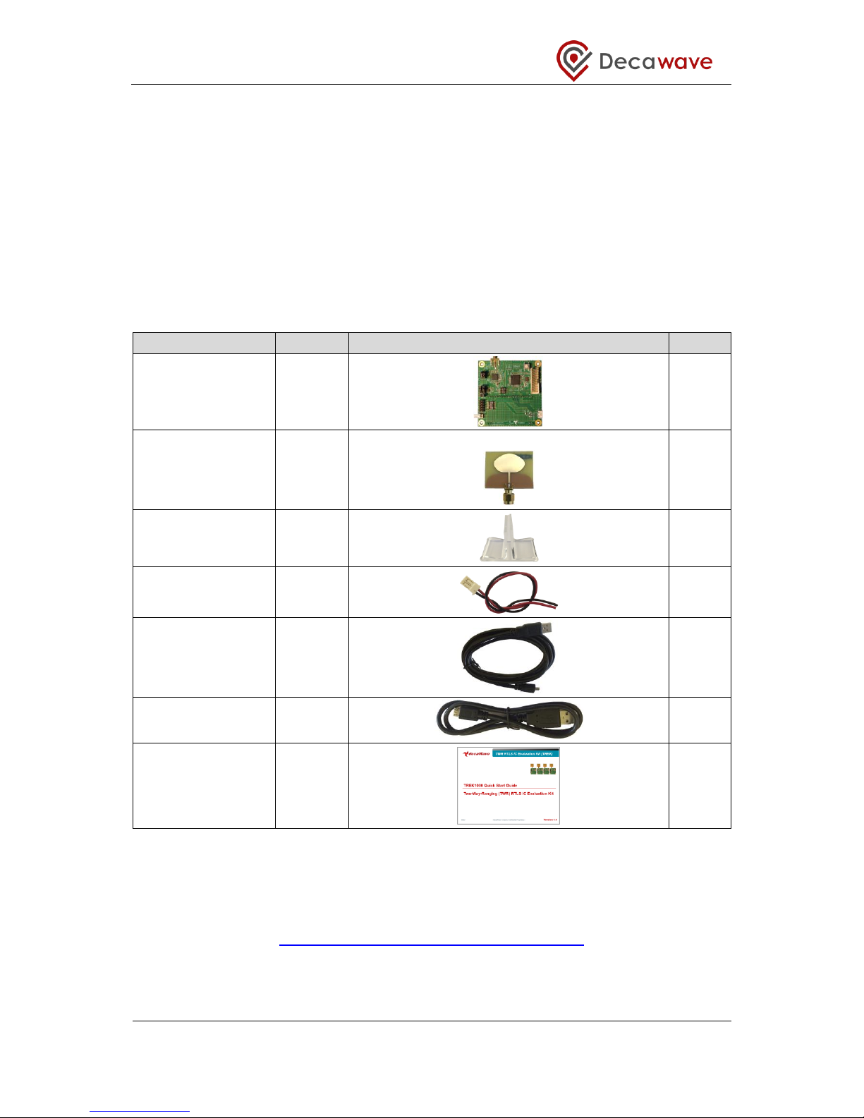
2.1 Supplied in the TREK1000 Box
The following items are delivered in the box when a TREK1000 kit is purchased.
Table 1: Kit Contents – In the Box
Description
Quantity
Image
Check
EVB1000 PCB
4
UWB Antenna
4
EVB1000 Stands
4
DC Power Leads
4
1.8 m USB Cable
3
60 cm USB Cable
1
Quick Start Guide
1
2.2 Available from the Decawave Website
Supporting documentation, instructional videos, reference source code and the application
UI should be downloaded from the Decawave website. Go to this URL to download:
http://www.decawave.com/products/TREK1000
The downloaded zip-file contains the following items: -

TREK1000 User Manual
© Decawave 2016 This document is confidential and contains information which is proprietary to
Decawave Limited. No reproduction is permitted without prior express written permission of the
author
Page 10 of 54
Table 2: Kit Contents – On the Website
Item
Description
Type
Check
Documentation
TREK1000 Quick Start Guide
Quick Setup Instructions
pdf
TREK1000 User Manual
Detailed description of setup,
installation and usage including User
Interface description
pdf
Moving from TREK1000 to a Product
Guidance on how to proceed from
evaluation to product design
pdf
TREK1000 Expansion Options
Options for mixing TREK1000 and
TREK1000 hardware to expand the
system
pdf
PC Application
DecaRangeRTLS PC
PC Application executable
exe
2.3 TREK1000 Source Code
TREK purchasers can get access to the ARM microcontroller source code, the PC
application source code and source code documentation.
If you are interested in accessing this source code and documentation then you should login
to the Decawave website (www.decawave.com) and proceed to the TREK1000 registration
page at http://www.decawave.com/trekreg. If you attempt to access this registration page
before you are logged in you will be redirected to the login page. Once on the registration
page, you will be asked to enter the serial number of your TREK1000 which can be found on
the outside of the box. Once the serial number has been verified you will be automatically
redirected to the TREK source code download page. Clicking on the download will launch a
disclaimer notice, which you will be asked to accept by ticking a box after which the
download of the source code package will commence.
The downloaded zip-file contains the following items: -
Table 3: TREK1000 Source Code Package
Item
Description
Type
Documentation
TREK1000 Source Code Guide:
DecaRangeRTLS PC
PC Application source code description
pdf
TREK1000 Source Code Guide:
DecaRangeRTLS ARM
ARM firmware source code description
pdf
Firmware
DecaRangeRTLS ARM
ARM firmware binary
bin
Software
DecaRangeRTLS PC
PC Application source code
zip
DecaRangeRTLS ARM
ARM firmware source code
zip
TREK1000 User Manual
© Decawave 2016 This document is confidential and contains information which is proprietary to
Decawave Limited. No reproduction is permitted without prior express written permission of the
author
Page 11 of 54
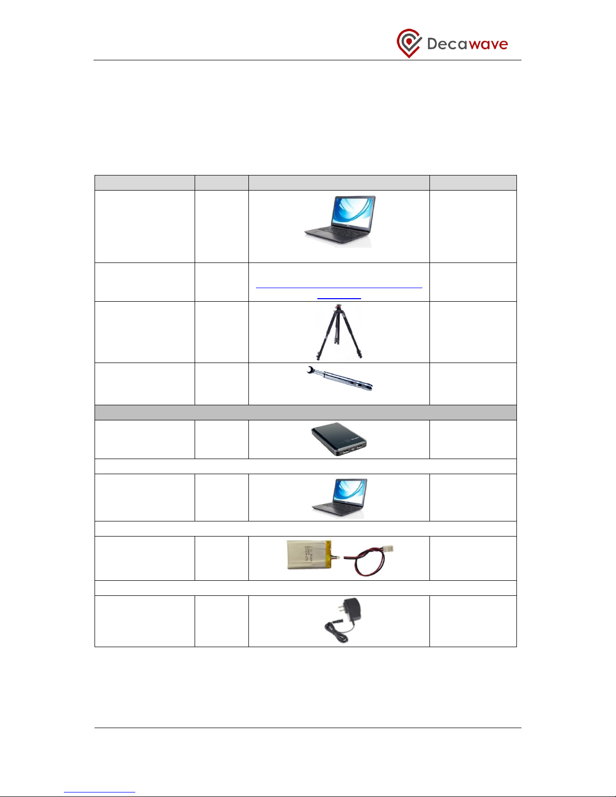
2.4 Items Not Included in the Kit
There are other items which may be used to install and use the TREK1000. Some are
required and some are useful.
These are listed in the table below.
Table 4: Kit Contents – Also Required or Useful, Not Provided
Description
Quantity
Image
Required?
PC
1
OS should be Windows 7 or 8
Required
STM32 Virtual COM
Port Driver
1
STSW-STM32102
http://www.st.com/web/en/catalog/tools/
PF257938
Required
Tripods
3-4 Useful
SMA Torque Wrench
1 Recommended
Options for Powering EVB1000 Units
USB Battery
3
OR
PC Connections
3
OR
Mobile Battery
3
OR
USB->Power
Adaptor
3
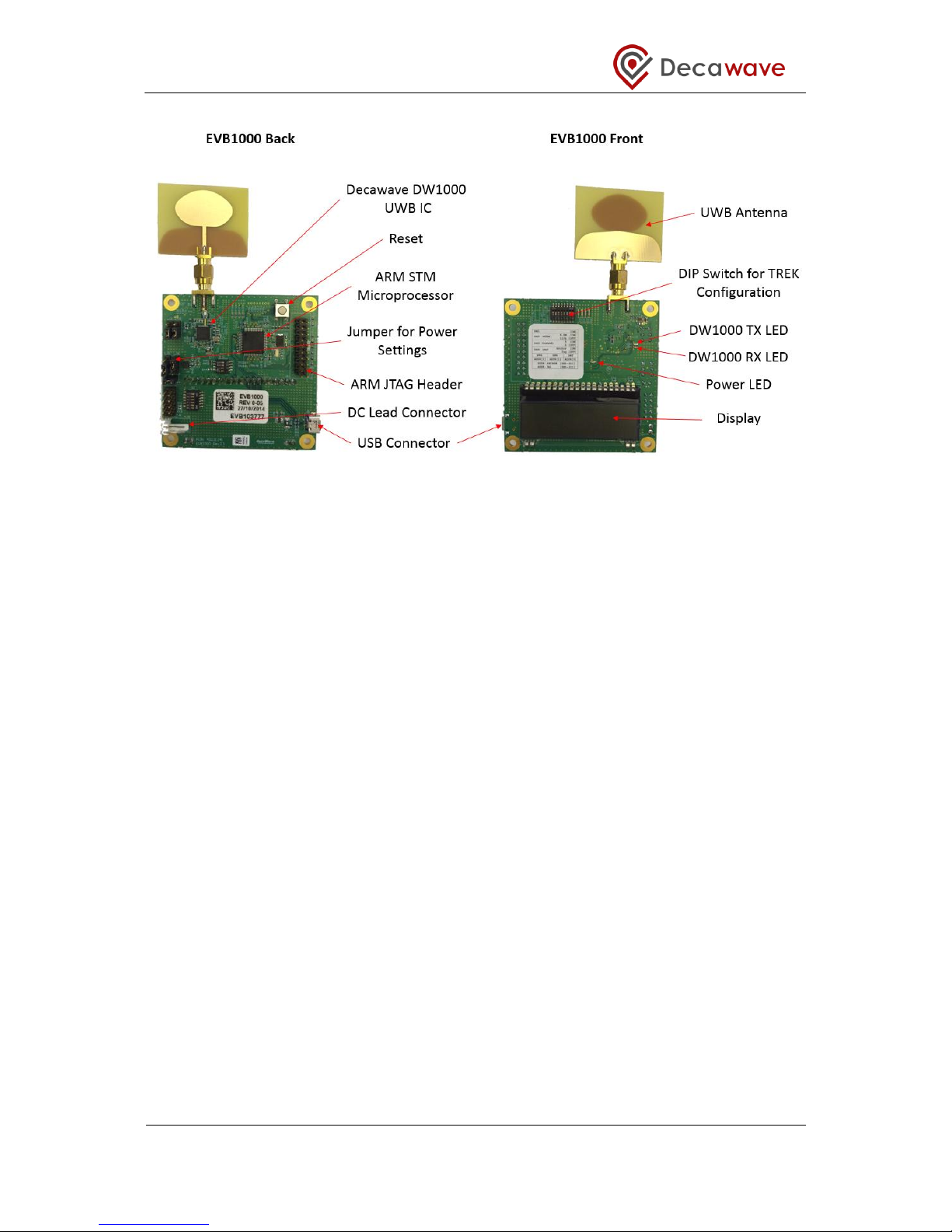
2.5 The EVB1000 Unit
The image below shows the key features of an EVB1000 unit.
TREK1000 User Manual
© Decawave 2016 This document is confidential and contains information which is proprietary to
Decawave Limited. No reproduction is permitted without prior express written permission of the
author
Page 12 of 54
Figure 2: Back and Front Views of an EVB1000
TREK1000 User Manual
© Decawave 2016 This document is confidential and contains information which is proprietary to
Decawave Limited. No reproduction is permitted without prior express written permission of the
author
Page 13 of 54
3 TREK1000 HARDWARE PREPARATION AND SETUP
This section details the steps necessary to prepare the TREK1000 hardware for use.
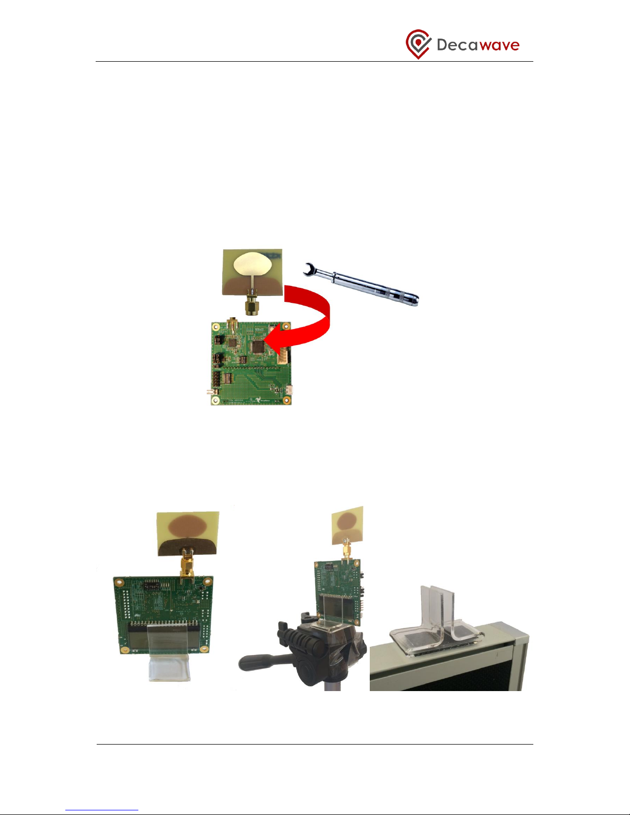
3.1 Connect the Antenna to the EVB1000 PCB
The 4 EVB1000 PCBs come with 4 UWB (Ultra-Wideband) antennas. Each antenna must be
screwed on to the EVB1000 using the SMA connector.
It is recommended that an SMA torque wrench is used to tighten the antenna to the
EVB1000.
Note that poor connections can result in under performance in the system.
Figure 3: Connect the Antenna to the EVB1000
3.2 Mounting Option for the EVB1000 Anchors
Depending on the use case that is being evaluated, 1 or more of the EVB1000 units will be
mounted.
Figure 4: EVB1000 Mounting Options Using the Stands
TREK1000 User Manual
© Decawave 2016 This document is confidential and contains information which is proprietary to
Decawave Limited. No reproduction is permitted without prior express written permission of the
author
Page 14 of 54
The figure above shows the EVB1000 sitting in the stands that are provided in the box.
The stands could be attached to a tripod, an office partition or any other flat surface for the
stand to sit on.
It is recommended that the stand be firmly clamped into place or fixed using tape or Velcro
tape to ensure the units do not move during testing.
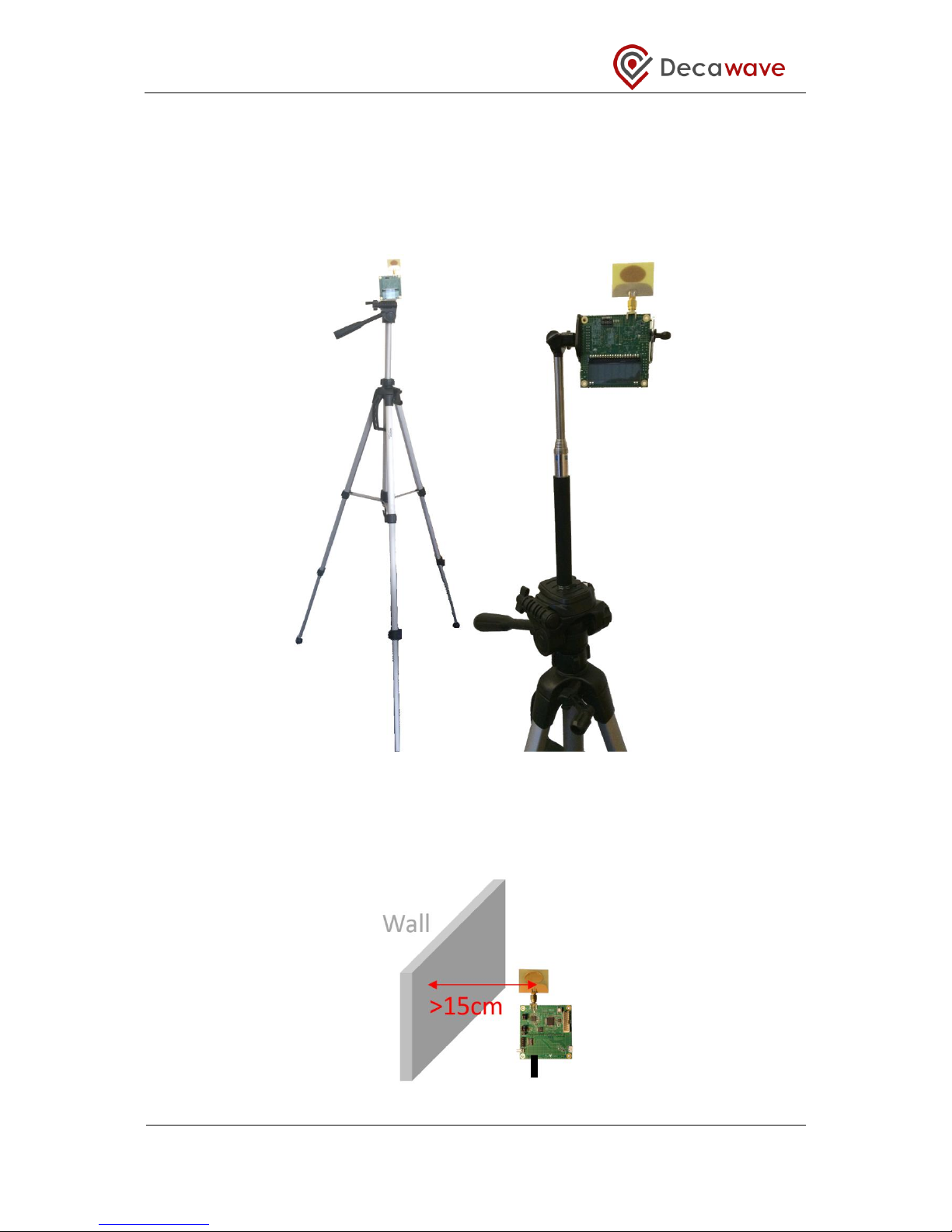
Figure 5: Mount EVB1000s on Tripods
When mounting the EVB1000 units do not place the antennas too close to walls or any
other objects as this can interfere with the radiation pattern of the antennas. It is
recommended that the antenna be greater than 15 cm away from the nearest object.
Figure 6: Do Not Place Antennas too Close to the Wall

TREK1000 User Manual
© Decawave 2016 This document is confidential and contains information which is proprietary to
Decawave Limited. No reproduction is permitted without prior express written permission of the
author
Page 15 of 54
When mounting the EVB1000 units on metal tripods or poles ensure that the top of the poles
are below the ground plane of the antennas. The ground plane of the antenna is considered
to be the top of the SMA connector under the antenna.
Figure 7: Keep Metal Objects below the Antenna
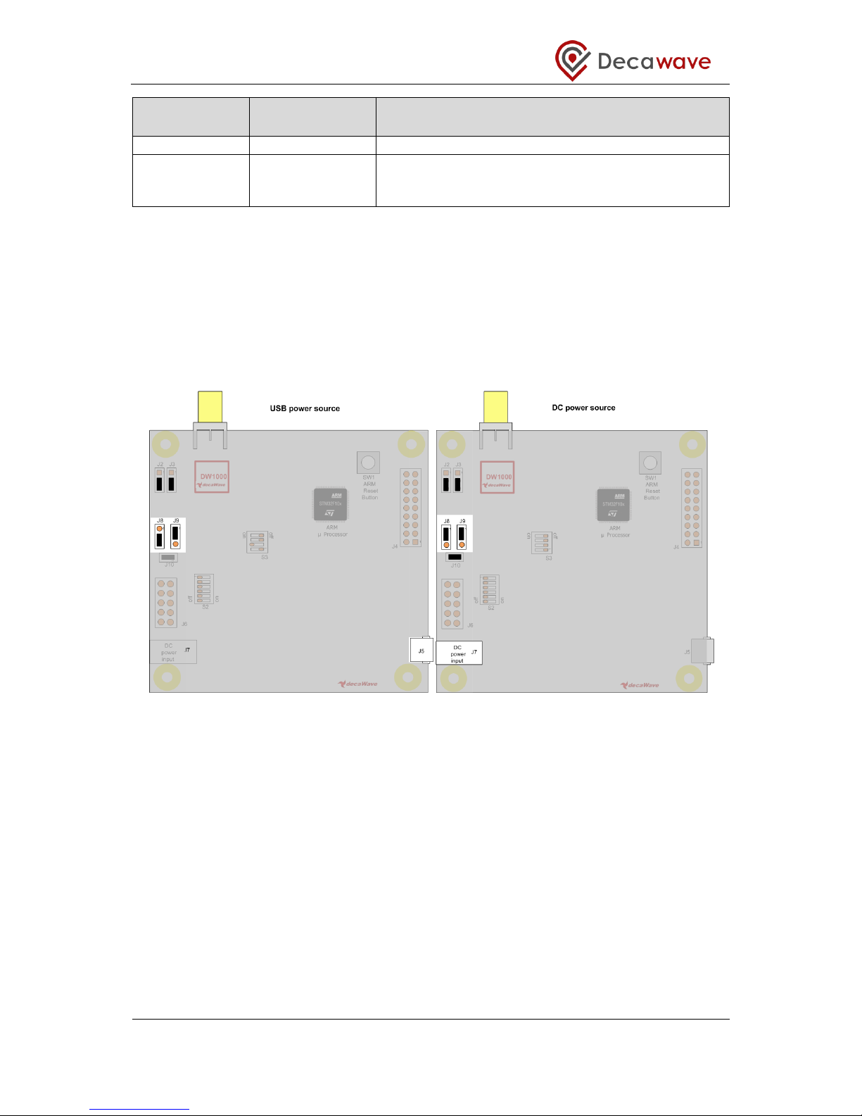
3.3 Powering the EVB1000
The EVB1000 can be powered either via an external DC power supply (or battery) through
jumper J7 on the back of the EVB1000 using the supplied power cable leads or via a
standard 5 V 500 mA USB power supply through jumper J5. To change between the two,
jumper J8 is used as shown in the figure below.
Figure 8: EVB1000 power supply options
Table 5: Power Option Settings
Power Source
J8
(Insert on pins)
Comment
USB
2 & 3
The USB port to which you connect the EVB1000 should
TREK1000 User Manual
© Decawave 2016 This document is confidential and contains information which is proprietary to
Decawave Limited. No reproduction is permitted without prior express written permission of the
author
Page 16 of 54
Power Source
J8
(Insert on pins)
Comment
be capable of supplying at least 250 mA
3.6 V to 5.5 V
1 & 2
In this mode the externally applied supply is indirectly
connected to the on-board circuitry through an LDO
regulator
Changes to jumper settings should only be made with the board powered down –
under no circumstances should jumper settings be changed while power is applied to
the board via any of the possible off-board connectors, or damage to the board may
result.
For the two power source options the positions of the jumpers are shown in Figure 9.
Jumpers J2 and J3 can be used to select whether sections of DW1000 are powered with 1.8
V or 3.3 V, for more details on this operation see Reference [1].
Figure 9: USB and DC 3.6V to 5.5V power source jumper connections
TREK1000 User Manual
© Decawave 2016 This document is confidential and contains information which is proprietary to
Decawave Limited. No reproduction is permitted without prior express written permission of the
author
Page 17 of 54
3.4 Configuring the EVB1000s
In the TREK1000 system there are 4 modes that can be evaluated:
Table 6: The 4 Modes of TREK1000
Mode
Mode
Description
Data
Rate
Channel
Location
Rate
PRF
Preamble
Length
Preamble
Code
L2
‘Long’ range
/ Chan. 2
110 kbps
2: 3.993 GHz
3.57 Hz
16 MHz
1024
4
L5
‘Long’ range
/ Chan. 5
110 kbps
5: 6.489 GHz
3.57 Hz
16 MHz
1024
3
S2
‘Short’ frame
/ Chan. 2
6.8 Mbps
2: 3.993 GHz
10 Hz
16 MHz
128
4
S5
‘Short’ frame
/ Chan. 5
6.8 Mbps
5: 6.489 GHz
10 Hz
16 MHz
128
3
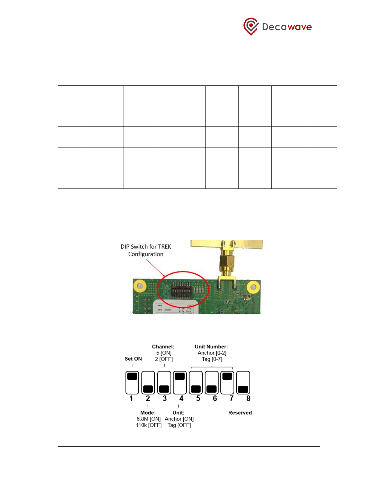
Also, each EVB1000 unit can be configured as either an Anchor or a Tag.
The configuration for each unit is set using the TREK configuration DIP switches (S1) on the
PCB.
Figure 10: EVB1000 TREK Configuration DIP Switches Location
Figure 11: EVB1000 TREK Configuration DIP Switches (S1) Functions

TREK1000 User Manual
© Decawave 2016 This document is confidential and contains information which is proprietary to
Decawave Limited. No reproduction is permitted without prior express written permission of the
author
Page 18 of 54
The DIP switch settings are described in the table below.
Table 7: DIP Switch (S1) Settings on an EVB1000
Switch
Function
Function
1
Reserved
This switch should be set to ON
2
MODE
ON: Data Rate = 6.8 Mbps
OFF: Data Rate = 110 kbps
3
CHANNEL
ON: Channel 5
OFF: Channel 2
4
UNIT
ON: Anchor
OFF: Tag
5
UNIT ID [2]
Set the ID numbers of the EVB1000 units.
Switch 7 is the LSB.
ID=1 => UNIT ID[2:0] = 001
6
UNIT ID [1]
7
UNIT ID [0]
8
Reserved
This switch should be set to OFF
The TREK configuration DIP Switches can be found on the front of the EVB1000 unit above
the display.
3.5 EVB1000 Display
When the EVB1000 is powered up there is a start-up screen appears containing the version
of DecaRangeRTLS ARM software that is running on the microprocessor.
Figure 12: EVB1000 Display Startup Screen
After about 20 s the display changes to show the current operating mode and the
configuration as Anchor or Tag.
Figure 13: EVB1000 Display Configuration Screen

TREK1000 User Manual
© Decawave 2016 This document is confidential and contains information which is proprietary to
Decawave Limited. No reproduction is permitted without prior express written permission of the
author
Page 19 of 54
Once the Tag and Anchors start communicating (two-way ranging) the Anchor-to-Tag
measured distances appears on the display. The display will cycle through the distances
from the unit with the display to the other units.
Figure 14: EVB1000 Display Ranging Screen

TREK1000 User Manual
© Decawave 2016 This document is confidential and contains information which is proprietary to
Decawave Limited. No reproduction is permitted without prior express written permission of the
author
Page 20 of 54
4 ARRANGEMENTS FOR DIFFERENT USE CASES
This section shows the arrangement of the EVB1000 units when evaluating the 3 different
topologies:
1. Tracking Use Case
2. Geo-Fencing Use Case
3. Navigation Use Case
4.1 Tracking Use Case
For evaluating the tracking use case the system is configured as:
3 Anchors
1 Tag
In this case example below: Channel 2, 110 kbps is selected as the operating mode.
The 3 Anchors are configured as shown below.
Figure 15: Tracking Use Case: Example Anchor Settings
The Tag is configured as shown below.
Figure 16: Tracking Use Case: Example Tag Settings

TREK1000 User Manual
© Decawave 2016 This document is confidential and contains information which is proprietary to
Decawave Limited. No reproduction is permitted without prior express written permission of the
author
Page 21 of 54
4.1.1 Arrangement
To demonstrate this use case the following setup is recommended:
Mount the 3 Anchors at the same height
Note: Differences in heights will result in reduced accuracy of location
Mount the 3 Anchors high enough where there is good Line-of-Sight (LOS) with no
obstructions between them e.g. mounting 2-3 m high would ensure they are above
people’s heads which will help avoid interference.
Mount the 3 Anchors to create a triangle
Ensure the antennas are >15 cm away from the nearest wall or any other objects
Connect the PC to one of the Anchors
Power the other 2 Anchors and the Tag using an external USB battery (or other
method)
Figure 17: Tracking Use Case: Arrangement
4.2 Geo-Fencing Use Case
For evaluating the tracking use case the system is configured as:
1 Anchor
3 Tags
In this case example below: Channel 2, 110 kbps is selected as the operating mode.
The Anchor is configured as shown below.
Figure 18: Geo-Fencing Use Case: Example Anchor Settings

TREK1000 User Manual
© Decawave 2016 This document is confidential and contains information which is proprietary to
Decawave Limited. No reproduction is permitted without prior express written permission of the
author
Page 22 of 54
The Tag is configured as shown below.
Figure 19: Geo-Fencing Use Case: Example Tag Settings
4.2.1 Arrangement
To demonstrate this use case the following setup is recommended:
Mount 1 Anchor on a stand
Ensure the antenna is >15 cm away from the nearest wall or any other objects
Connect the PC to this Anchor
Power the 3 Tags using external USB batteries (or other method)
Figure 20: Geo-Fencing Use Case: Arrangement

TREK1000 User Manual
© Decawave 2016 This document is confidential and contains information which is proprietary to
Decawave Limited. No reproduction is permitted without prior express written permission of the
author
Page 23 of 54
4.3 Navigation Use Case
The setup and arrangement for the Navigation Use Case is the same as the setup and
arrangement for the Tracking Use Case with the only difference being the PC is connected
to the Tag rather than the Anchor.
For evaluating the tracking use case the system is configured as:
3 Anchors
1 Tag
In this case example below: Channel 2, 110 kbps is selected as the operating mode.
The 3 Anchors are configured as shown below.
Figure 21: Navigation Use Case: Example Anchor Settings
The Tag is configured as shown below.
Figure 22: Navigation Use Case: Example Tag Settings
To demonstrate this use case the following setup is recommended:
Mount the 3 Anchors at the same height
Note: Differences in heights will result in reduced accuracy of location

TREK1000 User Manual
© Decawave 2016 This document is confidential and contains information which is proprietary to
Decawave Limited. No reproduction is permitted without prior express written permission of the
author
Page 24 of 54
Mount the 3 Anchors high enough where there is good Line-of-Sight (LOS) with no
obstructions between them e.g. mounting 2-3 m high would ensure they are above
people’s heads which will help avoid interference.
Mount the 3 Anchors to create a triangle
Ensure the antennas are >15 cm away from the nearest wall or any other objects
Connect the PC to the Tag
Power the 3 Anchors using external USB batteries (or other methods)
Figure 23: Navigation Use Case: Arrangement

TREK1000 User Manual
© Decawave 2016 This document is confidential and contains information which is proprietary to
Decawave Limited. No reproduction is permitted without prior express written permission of the
author
Page 25 of 54
5 TREK1000 SOFTWARE PREPARATION AND SETUP
This section details the software required to use the TREK1000.
5.1 Install the ST ARM USB Driver
In order to use the TREK1000 DecaRangeRTLS PC software the STM32 Virtual COM Port
Driver must first be downloaded and installed from:
http://www.st.com/web/en/catalog/tools/PF257938
This enables the PC to communicate with the EVB1000 units.
Note: After this driver has been downloaded please ensure to read the included readme.txt
as it contains further installation instructions.
5.2 Download the TREK1000 Zip-File
The TREK1000 documents and PC application can be downloaded in a zip-file from the
DecaWave website: http://www.decawave.com/.
Once downloaded unzip into a folder on the PC.
The zip-file contains the following folder structure.
- Collateral
- Documents
- Product Brief .pdf
- Quick Start Guide .pdf
- User Manual .pdf
- Moving from TREK1000 to a Product .pdf
- TREK1000 Expansion Options .pdf
- DecaRangeRTLS-PC
- DecaRangeRTLS .exe
- DLLs .dll
- Configuration Files .xml
5.3 Prepare the TREK1000 Software
There is no installation sequence necessary. Launch the PC application from
DecaRangeRTLS.exe in the DecaRangeRTLS-PC folder.

TREK1000 User Manual
© Decawave 2016 This document is confidential and contains information which is proprietary to
Decawave Limited. No reproduction is permitted without prior express written permission of the
author
Page 26 of 54
6 THE USER INTERFACE
This section describes the TREK1000 User Interface and usage.
6.1 Launch the User Interface
Connect the PC to Anchor 0 using any of the USB cables. Ensure the LEDs on Anchor ID
turn on and the TREK software message appears on the EVB1000 display.
Figure 24: User Interface: Startup Message
Note that this Anchor is powered directly from the USB connection to the PC – no external
power source is required.
Launch the PC application from DecaRangeRTLS.exe. This can be found in the
DecaRangeRTLS-PC folder.
If there is no USB connection from the PC to Anchor 0 the following error message will
appear.
Figure 25: User Interface: Startup – Error Message
In this case, make the connection to the EVB1000 unit, wait about 20 s and then click OK.
If problems persist then it may be necessary to modify the order in which COM port numbers
are assigned in the PC.
To do this, go to Device Manager -> Ports (COM and LPT), and see which devices are
assigned to which COM ports.
Select "STMicroelectronics Virtual COM Port (COMx)", and right click into “Properties”.
Select the “Port Settings” tab and click “Advanced”. Modify the COM port number associated
with this port. The chosen port number should be lower than all other assigned ports and
should be in the range 3 to 49.

TREK1000 User Manual
© Decawave 2016 This document is confidential and contains information which is proprietary to
Decawave Limited. No reproduction is permitted without prior express written permission of the
author
Page 27 of 54
If you are unsure how to do this or if problems persist contact your IT administrator.
6.2 User Interface: Startup
When the DecaRangeRTLS PC User Interface is first launched there will be 4 different
panes and a menu bar visible:
1. Anchor Table Pane
2. Tag Table Pane
3. Settings Pane
4. Display Pane
5. Menu Bar
Figure 26: User Interface: Startup View
6.3 Anchor Table Pane
The Anchor Table Pane lists the Anchors and the coordinates of the locations where they
were placed for the testing session.
For ease of use, it is recommended to put Anchor 0 in the (0, 0) x-y position. The user
should then manually enter the X, Y locations of the Anchors 1 and 2 relative to (0, 0).
The user should enter the height (z) of the Anchors. The User Interface only allows a single
value to be entered for all Anchors (for the first 3 Anchors) to remind the user that the
Anchors should be placed at the same height.
Note: The accuracy of the Tag location and tracking algorithm is strongly dependent on the
accuracy of the positioning (x, y and z) of the Anchors during setup so it is recommended to
take care during the setup stage. Differences in Anchor heights will result in reduced
accuracy of location.

TREK1000 User Manual
© Decawave 2016 This document is confidential and contains information which is proprietary to
Decawave Limited. No reproduction is permitted without prior express written permission of the
author
Page 28 of 54
Figure 27: User Interface: Anchor Table Pane
If ‘Show Anchor-Tag Correction Table’ is checked in the Settings:Configuration Pane, then a
table of manual adjustments appears so users can make manual location adjustments to the
Tag positions. This functionality is not necessary for TREK kits and the user should ensure
the values are all 0.
Figure 28: User Interface: Anchor Table Pane
6.4 Tag Table Pane
The Tag Table Pane displays information about the tags that are currently being tracked.
Figure 29: User Interface: Tag Table Pane – Tracking/Navigation Mode
The Tag Table Pane shows slightly different information whether the system is in
Tracking/Navigation Mode or Geo-Fencing Mode.

TREK1000 User Manual
© Decawave 2016 This document is confidential and contains information which is proprietary to
Decawave Limited. No reproduction is permitted without prior express written permission of the
author
Page 29 of 54
Figure 30: User Interface: Tag Table Pane – Geo-Fencing Mode
The field in the Tag Table Pane are:
Tag ID/Label Show/Hide the Tag label on the Display
Customize the label text – click on the label to edit
X (m) The x distance of the Tag from position (0, 0)
Y (m) The y distance of the Tag from position (0, 0)
Z (m) The z distance of the Tag from the ground
Requires the Anchor heights to be entered correctly
R95 (m) A measurement of precision of a Tag
Only meaningful for stationary Tags
Enable or disable this calculation
Anc 0 range (m) Measured distance between antennas of Anchor 0 and Tag
Anc 1 range (m) Measured distance between antennas of Anchor 1 and Tag
Anc 2 range (m) Measured distance between antennas of Anchor 2 and Tag
Anc 3 range (m) Measured distance between antennas of Anchor 3 and Tag
A 4th Anchor is not required in the standard TREK setup
6.5 Settings Pane
The settings pane appears to the right of the User Interface and has 3 tabs:
1. Configuration Tab
2. Floor Plan Tab
3. Grid Tab
6.5.1 Configuration Tab
The configuration tab contains general settings for use case modes and showing/hiding
features.
Switch between ‘Tracking/Navigation’ mode and ‘Geo-Fencing’ mode using the
checkboxes
In Geo-Fencing mode:
o Set 2 zone perimeters on the Display Pane – enter the desired perimeters in
metres
o Select ‘Alarm Outside’ or ‘Alarm Inside’ depending on whether the no-go area
is far from or near to the Anchor
Use Auto-Positioning:
o When ‘Use Auto-Positioning’ is checked, the system ignores the x, y anchor
co-ordinates that the user has entered and automatically calculates the
positions of the anchors.

TREK1000 User Manual
© Decawave 2016 This document is confidential and contains information which is proprietary to
Decawave Limited. No reproduction is permitted without prior express written permission of the
author
Page 30 of 54
o Anchor 0 and Anchor 1 are positioned on the x-axis and Anchor 2’s position is
calculated and positioned relative to them.
o The system continuously auto-positions and tunes the locations, so after the
locations have settled the user should uncheck the ‘Use Auto-Position’
checkbox to freeze the anchor locations.
o While Auto-Positioning is enabled the user cannot write x, y values into the
grid locations of Anchors 0, 1 or 2
Some basic filtering options are provided as an example
o None No filtering is applied
o Moving Average A length 10 moving average filter is applied
o Moving Avg. Ex. A length 10 moving average filter, excluding min value
and max value before averaging) is applied
Logging Enable/Disable:
o Enable or Disable location co-ordinates estimates and Tag-to-Anchor and
Anchor-to-Anchor range estimates to be written to a file
o A unique filename is created each time it is started
4 User Checkboxes:
o Show / Hide the Tag history
o Show / Hide the Anchor Table
o Show / Hide the Tag Table
o Show / Hide the Anchor-Tag Correction Table

TREK1000 User Manual
© Decawave 2016 This document is confidential and contains information which is proprietary to
Decawave Limited. No reproduction is permitted without prior express written permission of the
author
Page 31 of 54
Figure 31: User Interface: Settings Pane – Configuration Tab
Figure 32: User Interface: Auto-Positioning

TREK1000 User Manual
© Decawave 2016 This document is confidential and contains information which is proprietary to
Decawave Limited. No reproduction is permitted without prior express written permission of the
author
Page 32 of 54
Figure 33: User Interface: Filtering Options
Figure 34: User Interface: Enable Location Logging

TREK1000 User Manual
© Decawave 2016 This document is confidential and contains information which is proprietary to
Decawave Limited. No reproduction is permitted without prior express written permission of the
author
Page 33 of 54
Figure 35: User Interface: Hide Anchor and Tag Table Panes
The Settings Pane can also be hidden and then the Display Pane will be full screen. Click
the ‘X’ in the Settings Pane to remove it. To show the Settings Pane again use the View
Menu to select ‘Settings’.
Figure 36: User Interface: Show Display Pane Only
6.5.2 Floor Plan Tab
To upload a floorplan into the User Interface click ‘Open’ in the Floor Plan Tab. The floorplan
can be any image in .png, .jpg and .bmp formats.

TREK1000 User Manual
© Decawave 2016 This document is confidential and contains information which is proprietary to
Decawave Limited. No reproduction is permitted without prior express written permission of the
author
Page 34 of 54
Figure 37: User Interface: Settings Pane – Floor Plan Tab
After uploading the floorplan two additional options will appear:
Click the ‘Clear’ button to remove the floorplan from the GUI
Check the ‘Save Settings’ checkbox to remember the settings (Floorplan filename
and scaling settings). When the GUI application is closed and re-opened these
settings will be automatically loaded.
Figure 38: User Interface: Settings Pane – Floor Plan Tab – Clear & Save Settings
Once the floorplan image has been uploaded it will need to be resized, shifted and possibly
flipped to align with the 3 Anchor positions in the Display Pane.
A quick way to begin is to click ‘Set Origin’ and then click the location on the image where
Anchor 0 is placed. This automatically shifts the image so that Anchor 0 is positioned
correctly. Next, use the X Scale and Y Scale fields to resize the image.

TREK1000 User Manual
© Decawave 2016 This document is confidential and contains information which is proprietary to
Decawave Limited. No reproduction is permitted without prior express written permission of the
author
Page 35 of 54
Figure 39: User Interface: Position Floorplan
These are the floorplan options:
X Offset X position of the origin (0,0) point from the origin of the image
(i.e. bottom left hand corner) in pixels
Y Offset Y position of the origin (0,0) point from the origin of the image
(i.e. bottom left hand corner) in pixels
X Scale Used to relate how many pixels (in horizontal) in the image
correspond to 1m horizontal distance in reality
Y Scale Used to relate how many pixels (in vertical) in the image
correspond to 1m vertical distance in reality
Flip X Flip the image along a horizontal axis
Flip Y Flip the image along a vertical axis
Set Origin Set 0,0 coordinate in the floorplan
X Scale Measures the x-distance between any 2 points on the display
Select ‘X Scale’ and then click 2 points on the display
The x distance between the 2 points will be displayed
Y Scale Measures the y-distance between any 2 points on the display
Select ‘Y Scale’ and then click 2 points on the display
The y distance between the 2 points will be displayed

TREK1000 User Manual
© Decawave 2016 This document is confidential and contains information which is proprietary to
Decawave Limited. No reproduction is permitted without prior express written permission of the
author
Page 36 of 54
Figure 40: User Interface: Measure X-Scale on Display
6.5.3 Grid Tab
In the Grid Tab the distance between the dots shown in the Display Pane can be altered.
The vertical and horizontal distances can be adjusted independently. Enter the desired
distances in metres.
The grid can also be hidden or shown using the ‘Show Grid’ checkbox.
Figure 41: User Interface: Settings Pane – Grid Tab
6.6 Display Pane
The Display Pane shows the positions of the Anchors and Tags. Each Anchor and Tag can
be displayed or hidden using the checkboxes in the Anchor Table Pane and the Tag Table
Pane.
The Grid can be configured in the Settings Pane:Grid Tab.

TREK1000 User Manual
© Decawave 2016 This document is confidential and contains information which is proprietary to
Decawave Limited. No reproduction is permitted without prior express written permission of the
author
Page 37 of 54
The Anchor and Tag labels can be configured in the Anchor Table Pane and the Tag Table
Pane.
6.7 Minimap Pane
The Minimap Pane can be made visible in the View menu. It is only operational if a floorplan
has been loaded into the User Interface.
Using the mouse, the user can select different regions of the floorplan to be displayed in the
Display Pane beside it.
Figure 42: User Interface: Minimap Pane
6.8 Menu Bar
The DecaRangeRTLS menu options are:
View Menu
Help Menu
Figure 43: User Interface: Menus

TREK1000 User Manual
© Decawave 2016 This document is confidential and contains information which is proprietary to
Decawave Limited. No reproduction is permitted without prior express written permission of the
author
Page 38 of 54
6.8.1 View Menu
The View Menu contains options to enable showing or hiding of DecaRangeRTLS panes:
Settings Toggle between showing or hiding the Settings Pane
Minimap Toggle between showing or hiding the Minimap Pane (this is
only operational if a floorplan has been uploaded)
6.8.2 Help Menu
The Help Menu contains an About Us message.
Figure 44: User Interface: About Us

TREK1000 User Manual
© Decawave 2016 This document is confidential and contains information which is proprietary to
Decawave Limited. No reproduction is permitted without prior express written permission of the
author
Page 39 of 54
7 USAGE
This section describes how to use the User Interface for evaluating the different use cases.
Note: To change between tracking and navigation use cases the user must disconnect the
USB cable from the PC, shut down the PC Application and reconnect the USB before
restarting the PC Application.
7.1 Navigation or Tracking Use Cases
1. Configure the DIP switches on the 4 EVB1000 units1:
a. Set switch 1 to [ON]
b. Select a data rate with switch 2: 6.8 Mbps [ON], 110 kbps [OFF]
c. Select a channel with switch 3: Channel 5 [ON], Channel 2 [OFF]
d. Configure 3 units as Anchors: switch 4 is [ON]
e. Configure 1 unit as a Tag: switch 4 is [OFF]
f. Set the ID of the Tag to 0: switches 5,6 & 7 [OFF]
g. Set the IDs of the Anchors to 0, 1 & 2: switches 5,6,7 = [000, 001, 010]
h. Switch 8 is reserved so this can be [ON] or [OFF]
2. Mount the 3 Anchors at the same height
3. Measure the coordinates of the Anchors3 using a laser pointer or other accurate
method. Alternatively, use the Auto-Positioning feature to measure coordinates.
4. Power the Anchors and Tags using one of the following methods:
a. USB power supply (not provided)2
b. USB battery pack (not provided)
c. Connect to a PC (not provided)
d. Connect to a mobile battery (not provided) using the DC leads (provided)
5. Connect the PC:
a. For Tracking Use Case: Connect Anchor 0 to the PC
b. For Navigation Use Case: Connect the Tag to the PC
6. Wait for the start message to disappear and then the TREKs are ready (about 20 s)
7. Start the DecaRangeRTLS PC Application
a. Check ‘Navigation/Tracking Mode’ in the Configuration Tab of Settings
8. Enter the Anchor locations into the Anchor Table Pane - note the Anchor heights (z)
must be the same:
a. Set Anchor 0 to coordinates (0, 0, z)
b. Set Anchor 1 to measured coordinates (x1, y1, z)
c. Set Anchor 2 to measured coordinates (x2, y2, z)
9. Track the Tag as it moves around the zone created by the Anchors
1
Setup Note 1: If the system does not operate as expected when the settings of any of the
DIP switches are changed it may be necessary to operate the switches a number of times.
They have been known to stick and not operate correctly. Toggling them a number of times
generally resolves the issue.

TREK1000 User Manual
© Decawave 2016 This document is confidential and contains information which is proprietary to
Decawave Limited. No reproduction is permitted without prior express written permission of the
author
Page 40 of 54
2
Setup Note 2: Some USB battery packs may not power the Tag correctly. The Tag
periodically goes into a sleep state before waking up to perform a two-way range and
returning to sleep. During sleep the current consumption may be too low to keep the USB
battery pack on and the battery may shut off. Not all battery packs turn off. For battery
packs that have a torch function the user can switch the torch function on to keep the battery
alive during the sleep state.
3
Setup Note 3: The accuracy with which the Anchors are placed and the coordinates
measured has an impact on the accuracy of the system as a whole. It is recommended to
take care at this stage to ensure distances are measured correctly to ensure good
performance later.
7.2 Geo-Fencing Use Case
1. Configure the DIP switches on the 4 EVB1000 units1:
a. Set switch 1 to [ON]
b. Select a data rate with switch 2: 6.8 Mbps [ON], 110 kbps [OFF]
c. Select a channel with switch 3: Channel 5 [ON], Channel 2 [OFF]
d. Configure 3 units as Tags: switch 4 is [OFF]
e. Configure 1 unit as an Anchor: switch 4 is [ON]
f. Set the ID of the Anchor to 0: switches 5,6 & 7 [OFF]
g. Set the IDs of the Tags to 0, 1 & 2: switches 5,6,7 = [000, 001, 010]
h. Switch 8 is reserved so can be [ON] or [OFF]
2. Mount the Anchor
3. Power the Tags using one of the following methods:
a. USB power supply (not provided)2
b. USB battery pack (not provided)
c. Connect to a PC (not provided)
d. Connect to a mobile battery (not provided) using the DC leads (provided)
4. Connect the PC to the Anchor
5. Wait for the start message to disappear and then the TREKs are ready (about 20 s)
6. Start the DecaRangeRTLS PC Application
a. Check ‘Geo-Fencing Mode’ in the Configuration Tab of Settings
7. Enter the zone perimeters into the Configuration Tab
8. Select ‘Alarm Inside’ or ‘Alarm Outside’
9. In Geo-Fencing mode the Tag is displayed as a circle as opposed to a true location
10. As a Tag enters or leaves each of the zones (i.e. crosses a perimeter) the Tag’s
circle changes color from red to blue to green
1
Setup Note 1: If the system does not operate as expected when the settings of any of the
DIP switches are changed it may be necessary to operate the switches a number of times.
They have been known to stick and not operate correctly. Toggling them a number of times
generally resolves the issue
2
Setup Note 2: Some USB battery packs may not power the Tag correctly. The Tag
periodically goes into a sleep state before waking up to perform a two-way range and
returning to sleep. During sleep the current consumption may be too low to keep the USB
battery pack on and the battery may shut off. Not all battery packs turn off. For battery
packs that have a torch function the user can switch the torch function on to keep the battery

TREK1000 User Manual
© Decawave 2016 This document is confidential and contains information which is proprietary to
Decawave Limited. No reproduction is permitted without prior express written permission of the
author
Page 41 of 54
alive during the sleep state.

TREK1000 User Manual
© Decawave 2016 This document is confidential and contains information which is proprietary to
Decawave Limited. No reproduction is permitted without prior express written permission of the
author
Page 42 of 54
8 ANALYSIS
This section contains some notes about analysis and interpretation of results.
8.1 Log Files
During a TREK session each transaction between Anchor and Tag is recorded into a log file
which can be post-processed and analysed after the testing session.
The log file can be found in the Logs folder and the name is of the format:
yyyymmdd_hhmmssRTLS_log.txt
8.1.1 Range Report Format
There are three ranging report messages sent over the USB port:
1. mr 0f 000005a4 000004c8 00000436 000003f9 0958 c0 40424042 a0:0
2. ma 07 00000000 0000085c 00000659 000006b7 095b 26 00024bed a0:0
3. mc 0f 00000663 000005a3 00000512 000004cb 095f c1 00024c24 a0:0
The “mr” message consists of tag to anchor raw ranges, “mc” tag to anchor range bias corrected
ranges – used for tag location and “ma” anchor to anchor range bias corrected ranges – used for
anchor auto-positioning.
MID MASK RANGE0 RANGE1 RANGE2 RANGE3 NRANGES RSEQ DEBUG aT:A
MID this is the message ID, as described above: mr, mc and ma
MASK this states which RANGEs are valid, if MASK=7 then only RANGE0, RANGE1 and RANGE2
are valid (in hex, 8-bit number)
RANGE0 this is tag to anchor ID 0 range if MID = mc/mr (in mm, 32-bit hex number)
RANGE1 this is tag to anchor ID 1 range if MID = mc/mr or anchor 0 to anchor 1 range if MID =
ma (in mm, 32-bit hex number)
RANGE2 this is tag to anchor ID 2 range if MID = mc/mr or anchor 0 to anchor 2 range if MID =
ma (in mm, 32-bit hex number)
RANGE3 this is tag to anchor ID 3 range if MID = mc/mr or anchor 1 to anchor 2 range if MID =
ma (in mm, 32-bit hex number)
NRANGES this is a number of ranges completed by reporting unit raw range (16-bit hex number)
RSEQ this is the range sequence number (8-bit hex number)
DEBUG this is the TX/RX antenna delays (if MID = ma) – two 16-bit numbers or time of last
range reported – if MID = mc/mr (32 bit hex number)
aT:A the T is the tag ID and A id the anchor ID
The figure below shows how to interpret the messages in the log files.

TREK1000 User Manual
© Decawave 2016 This document is confidential and contains information which is proprietary to
Decawave Limited. No reproduction is permitted without prior express written permission of the
author
Page 43 of 54
Figure 45: Reading the Log Files
The “mr” message consists of tag to anchor raw ranges, “mc” tag to anchor range bias corrected
ranges – used for tag location and “ma” anchor to anchor range bias corrected ranges – used for
anchor auto-positioning.
For further information on the Range Report Format see ref[5]
8.2 Z-Height
The TREK1000 system estimates x, y and z data for the Tag. The user should be aware
that as there are only 3 Anchors in this system the trilateration location algorithm returns 2
solutions – one above the plane of the Anchors and one below the plane of the Anchors.
The TREK system only selects the lower of the two results thereby assuming the Anchors
are above the Tag.
TS: Tag Statistics (last 100 LEs): Tag ID:Average x:Average y:Average z:R95
NL: No Location
RA: Anchor to Anchor Range Report: Anchor ID:Anchor ID:Range:0:Sequence #:Range Number

TREK1000 User Manual
© Decawave 2016 This document is confidential and contains information which is proprietary to
Decawave Limited. No reproduction is permitted without prior express written permission of the
author
Page 44 of 54
Figure 46: Trilateration – 2 Solutions Exist
For systems that only measure x and y, or systems that mount the Anchors above the Tag,
this is sufficient.
8.2.1 Adding a 4th Anchor (example only)
A 4th Anchor is not required if:
1. the Tag is always below the plane of the 3 Anchors, or
2. the system only requires x-y co-ordinates (2D) and the z-height is not required (3D)
A 4th Anchor would be required to resolve the 2 solutions if the Tag can be located above or
below the plane of the Anchors.
If a 4th Anchor is added, TREK1000 uses data from that anchor to select the correct solution
from the 2 returned solutions.
Method:
Add the 4th Anchor on a different plane than the first 3 anchors. It is recommended to mount
it above the other 3 Anchors to give better line-of-sight to the Tag (less obstructions from
people, furniture etc.)
Figure 47: Adding a 4th Anchor
For best performance, the difference in height between 4th Anchor and the plane of the
others should be as large as possible.
The solution selected is the minimum of ABS(R – D1) and ABS(R – D2), where D1, D2 are

TREK1000 User Manual
© Decawave 2016 This document is confidential and contains information which is proprietary to
Decawave Limited. No reproduction is permitted without prior express written permission of the
author
Page 45 of 54
estimated from the co-ordinates and R is the range from the Tag to Anchor A3.
Note: Any errors in the z-height result (e.g. from Two-Way-Ranging errors) could push the
solution across the plane of the 3 Anchors and produce an incorrect solution.
Note: This is an example methodology. Other methods & algorithms may be more
suited to the end application - this is left up to the system designer to investigate
other algorithms and change the code as appropriate to their application.

TREK1000 User Manual
© Decawave 2016 This document is confidential and contains information which is proprietary to
Decawave Limited. No reproduction is permitted without prior express written permission of the
author
Page 46 of 54
9 OTHER EVB1000 BOARD DETAILS
This section gives further details of the EVB1000 including the pin-outs of all connectors and
the function of all the on-board switches and Jumpers.
TREK1000 can be operated as described previously without knowledge of these connectors.
9.1 Off-board connector headers
9.1.1 J1 – SMA antenna connector
External antenna connector
Table 8: J1 pin out
Pin
Function
J1-Centre
RF signal
J1-Body
Ground
9.1.2 J4 – JTAG connector
The JTAG connector is intended for connection to an external ARM debug interface /
development toolset. DIL Header, 20 pin, 0.1” pitch.
Table 9: J4 pin-out
Function
Pin
Pin
Function
VCC
1 2 VCC
JTRST
3 4 GND
J TDI
5 6 GND
J TMS
7 8 GND
J TCK
9
10
GND
Pulled to GND via 10kΩ resistor
11
12
GND
J TDO
13
14
GND
ARM_RESET
15
16
GND
Pulled to GND via 10kΩ resistor
17
18
GND
Pulled to GND via 10kΩ resistor
19
20
GND
9.1.3 J5 – Micro USB connector
This is the micro USB connector.
Table 10: Micro USB connector pin-out
Pin
Function
J5-1
VSUB +5 V IN
J5-2
USBDM to ARM GPIO PA11
J5-3
USBDP to ARM GPIO PA12

TREK1000 User Manual
© Decawave 2016 This document is confidential and contains information which is proprietary to
Decawave Limited. No reproduction is permitted without prior express written permission of the
author
Page 47 of 54
Pin
Function
J5-4
ID to ARM GPIO PA10
J5-5
GND
9.1.4 J6 – External SPI connector
The external SPI connector is intended for connection to an external microcontroller or to a
PC via a USB to SPI converter (The pin-out of has been arranged to be compatible with that
of the “Cheetah” series of SPI to USB converters provided by TotalPhase
TM
), DIL Header, 10
pin, 0.1” pitch.
Figure 48: Logical view of the EVB1000
Table 11: J6 Pin-out
Function
Pin
Pin
Function
Not Connected
1 2 GND
WAKEUP (fit R41, 0Ω) - refer Figure 48
3 4 IRQ (fit R43, 0Ω) - refer Figure 48
MISO – SPI Data out to PC / External
Micro
5 6 Not Connected
SCK – SPI Clock from PC / External
Micro
7
8
MOSI – SPI Data in from PC /
External Micro
SPI CSn – SPI Chip Select from PC /
External Micro
9
10
GND
DW1000 SUBSYSTEM
ARM SUBSYSTEM
POWER
SUBSYSTEM /
POWER
SOURCE
SELECTION
+5 V DC input from USB
J1
Antenna
Connector
J5
USB
Connector
J7
+3V6 /
+5V5DC
S2
Always
Connected
SPI I/F
R43 (DNF / 0Ω)
R41 (DNF / 0Ω)
IRQn
WAKEUP
J6
SPI I/F to
external
computer

TREK1000 User Manual
© Decawave 2016 This document is confidential and contains information which is proprietary to
Decawave Limited. No reproduction is permitted without prior express written permission of the
author
Page 48 of 54
9.1.5 J7 – External DC supply
Optional external DC power supply pin. SIL 2 pin 0.1” pitch
Table 12: J7 pin-out
Pin
Function
J7-1 (GND)
Ground
J7-2 (+VE)
DC supply can be from +3.6 V to +5.5 V

TREK1000 User Manual
© Decawave 2016 This document is confidential and contains information which is proprietary to
Decawave Limited. No reproduction is permitted without prior express written permission of the
author
Page 49 of 54
9.2 On-board switch functions
9.2.1 S1
S1 is a SPST 8-way switch. Its various functions are described in the Section 3 above.
9.2.2 S2
S2 is a SPST 6-way switch. Its various functions are described in the table below. It disables
the DW1000 SPI bus connections to the onboard ARM processor.
Table 13: S2 switch configuration descriptions
Switch
ALL Off
function
All On
function
Description
S2
Disables
ARM SPI
connection
to DW1000
Enables
ARM SPI
connection
to DW1000
If the onboard ARM functionality is not required
this switch can be turned off to disable ARM SPI
connection to the DW1000.
9.2.3 S3
S3 is a SPST 4-way switch. Its various functions are described in the table below.
Table 14: S3 switch configuration descriptions
Switch
Off
function
On
function
Description
S3-1
Disconnects
onboard
ARM PA0
GPIO to
DW1000
RSTn pin
Connects
onboard
ARM PA0
GPIO to
DW1000
RSTn pin
If used it allows ARM GPIO PA0 pin to connect
to DW1000 RSTn pin. This allows ARM to reset
the DW1000.
This should be on when running the
onboard ARM application.
S3-2
Disables
LED 0
Enables
LED 0
Can be used to enable or disable LED 0.
(current consumption measurement)
S3-3
Selects
DW1000
SPI mode
Selects
DW1000
SPI mode
This switch can be used to select DW1000 SPI
mode it is connected to DW1000 GPIO 5 pin.
For more information see Reference [2].
S3-4
Selects
DW1000
SPI mode
Selects
DW1000
SPI mode
This switch can be used to select DW1000 SPI
mode it is connected to DW1000 GPIO 6 pin.
For more information see Reference [2].

TREK1000 User Manual
© Decawave 2016 This document is confidential and contains information which is proprietary to
Decawave Limited. No reproduction is permitted without prior express written permission of the
author
Page 50 of 54
9.2.4 SW1
This is the ARM reset button.
Table 15: SW1 ARM reset button
Switch
Pressed
Released
Description
SW1
Forces
hardware
reset of
ARM
processor
Allows ARM
processor
to operate
normally
Is used to allow reset the ARM processor.
9.3 On-board 2-pin jumper functions
Table 16: J10 function
Jumper
In
Out
Description
J10
Connects
main 3.3V
power from
DW1000
Disconnects
main 3.3V
power from
DW1000
Enables DW1000 power/current measurement.
9.4 On-board 3-pin headers with jumper functions
9.4.1 J2 and J3 functions
Table 17: J2 and J3 functions
Jumper
In pins 1 & 2
In pins 2 & 3
Out
Description
J2
DW1000 uses 3.3
V supply for
VDDLDO
DW1000 uses
external DCDC 1V8 supply
for VDDLDO as
current saving
option
DW1000
VDDLDO
power
disconnected
For more information
see Reference [2].
J3
DW1000 uses 3.3
V supply for
VDDLDO2
DW1000 uses
external DCDC 1V8 supply
for VDDLDO2
as current
saving option
DW1000
VDDLDO2
power
disconnected
For more information
see Reference [2].

TREK1000 User Manual
© Decawave 2016 This document is confidential and contains information which is proprietary to
Decawave Limited. No reproduction is permitted without prior express written permission of the
author
Page 51 of 54
9.4.2 J8 and J9 functions
Table 18: J8 and J9 functions
Jumper
In pins 1 & 2
In pins 2 & 3
Out
Description
J8
Enables EVB1000
powering from J6
Enables
EVB1000
powering from
J5
EVB1000 is not
powered
Enables different
power configuration
options.
J9
In this mode the
externally applied
supply is
connected to the
onboard circuitry
through a 3.3V
voltage regulator
n/a
Voltage
regulator is
disconnected –
EVB1000 is not
powered.
Must be connected
for EVB1000 power.

TREK1000 User Manual
© Decawave 2016 This document is confidential and contains information which is proprietary to
Decawave Limited. No reproduction is permitted without prior express written permission of the
author
Page 52 of 54
10 REFERENCES
10.1 Listing
Reference is made to the following documents in the course of this Application Note: -
Table 19: Table of References
Ref
Author
Date
Version
Title
[1]
Decawave
Current
DW1000 Data Sheet
[2]
Decawave
Current
DW1000 User Manual
[3]
Decawave
Current
TREK1000 Product Brief
[4]
Decawave
Current
TREK1000 Quick Start Guide
[5]
Decawave
Current
TREK1000 Source Code Guide:
DecaRangeRTLS PC
[6]
Decawave
Current
TREK1000 Source Code Guide:
DecaRangeRTLS ARM
[7]
Decawave
Current
Moving from TREK1000 to a Product
11 DOCUMENT HISTORY
Table 20: Document History
Revision
Date
Description
1.08
5th June 2018
New logo update
1.07
30th June 2016
Scheduled update
1.06
9th February 2016
Updated descriptions of modes, floorplan/GUI, 4th
anchor usage, displayed ranges and EVB1000
connectors.
1.05
28th September 2015
Updated to match 2.06 software release
1.04
30th June 2015
Scheduled update
1.03
31st March 2015
Initial release
12 MAJOR CHANGES
Revision 1.08
Page
Change Description
Front page
Update with new logo
Include description of MR, MC and MA
Revision 1.07
Page
Change Description
Front page
Change revision number to 1.07
10
Modification of registration procedure for TREK source code access
40
Update log descriptions to include RA – anchor-to-anchor ranges.
44
Fix missing references in Table 11.

TREK1000 User Manual
© Decawave 2016 This document is confidential and contains information which is proprietary to
Decawave Limited. No reproduction is permitted without prior express written permission of the
author
Page 53 of 54
Revision 1.06
Page
Change Description
Front page
Change revision number to 1.06
16
Updated description of modes of operation to include configurations
17
Changed switch 8 description to be OFF
18
Changed description of ranges on screen to be a cycle of ranges
33
Updated GUI to include new floorplan functionality
37
Updated about dialog box image
41
Updated description of the usage and limitations of the 4th anchor
43
Added new section describing all board connectors and headers
48
Include this table
Revision 1.05
Page
Change Description
Front page
Change revision number to 1.05
17, 26
Update display image
27
GUI image updates
29-32
New configuration feature descriptions: Auto-Positioning, Filtering, Logging
37
Updated ‘about’ image
38
Added Auto-Position as a setup option for navigation/tracking use cases
43
Include this table
Revision 1.04
Page
Change Description
Front page
Change revision number to 1.04
25
Add note on changing COM port number assignments in PC
35, 36
Add notes on sticking DIP switches
39
Include 1.04 in revision history table
39
Include this table
Revision 1.03
Page
Change Description
All
Initial Release

TREK1000 User Manual
© Decawave 2016 This document is confidential and contains information which is proprietary to
Decawave Limited. No reproduction is permitted without prior express written permission of the
author
Page 54 of 54
13 FURTHER INFORMATION
Decawave develops semiconductors solutions, software, modules, reference designs - that
enable real-time, ultra-accurate, ultra-reliable local area micro-location services.
Decawave’s technology enables an entirely new class of easy to implement, highly secure,
intelligent location functionality and services for IoT and smart consumer products and
applications.
For further information on this or any other Decawave product, please refer to our website
www.decawave.com.
 Loading...