

Decatur Electronics SVR DUAL User Manual
SVR DUAL
Surface Velocity Radar
With
Water Level Sensor
™
User’s Manual
Rev 5-2-19

Table of Contents
Welcome .............................................................6
About This Manual ....................................................7
1 Safety Information ....................................................7
2 Receiving Inspection ..................................................8
3 Getting Started .......................................................9
3.1 Introduction ......................................................9
3.2 SVR Dual™ Panel Connector .......................................9
3.3 Connecting the Standard Serial Cable ............................10
3.4 Mounting Conguration .........................................11
3.5 Mounting Examples..............................................11
3.6 Mounting Options ...............................................12
4 Conguring the SVR Dual™ ...........................................13
4.1 Equipment Needed ..............................................13
4.2 Set Up ...........................................................13
4.3 Conguration Program Screen ...................................13
4.4 Conguration Items Screen ......................................17
4.4.1 Address (1-247) for Modbus....................................17
4.4.2 Software Version & Unit ID .....................................17
4.4.3 Measurement..................................................17
4.4.4 Target Report ..................................................18
4.4.5 Target Average ................................................19
4.4.6 Auto/Manual Vertical COS Adjustment .........................19
4.4.7 Cosine Horizontal and Cosine Vertical ..........................20
4.4.8 Hold Time .....................................................21
4.4.9 Update Rate ...................................................21
4.4.10 Sensitivity ....................................................21
4.4.11 Water Distance Sensor Duty Cycle .............................21
4.4.12 RS485 or 4-20 mA Loop .......................................22
4.4.13 Baud Rate ....................................................22
4.4.14 Serial Protocol . . . . . . . . . . . . . . . . . . . . . . . . . . . . . . . . . . . . . . . . . . . . . . . . 22
4.5 Loading New Firmware & Conguring the SVR Dual™ .............24
4.6 Conguration Notes .............................................27
4.7 Surface Velocity Radar SVR Dual™ Command Set ..................28
4.7.1 Commands ....................................................28
4.7.2 How to Check Congure Settings...............................32

5 Performance Tips ....................................................33
5.1 How Radar Works ................................................33
5.2 Selecting the Correct Site ........................................34
5.3 Interference Sources and Remedies ..............................35
5.3.1 Angular Interference (Cosine Eect) ............................36
5.3.2 Electromagnetic Interference (EMI) .............................37
5.3.3 Feedback Interference .........................................37
5.3.4 Multi-Path Beam Cancellation ..................................37
5.3.5 Radio Frequency Interference (RFI) .............................37
5.3.6 Scanning . . . . . . . . . . . . . . . . . . . . . . . . . . . . . . . . . . . . . . . . . . . . . . . . . . . . . . 37
5.3.7 Environmental Factors: Wind, Rain, Snow .......................38
6 Care, Cleaning, and Storage ..........................................38
7 Specications ........................................................39
7.1 Antenna Parameters .............................................39
7.2 Environment ....................................................39
7.3 Speed Range Parameters ........................................39
7.4 Power Consumption ............................................39
7.5 Water Distance Sensor Parameters................................40
8 Legal Requirements ..................................................41
8.1 Documents ......................................................41
8.2 FCC Statement...................................................42
8.3 Conditions.......................................................42
8.4 Installer Note ....................................................42
8.5 End User Note ...................................................42
9 Frequently Asked Questions (FAQ) ....................................42
10 Warranty.............................................................43
11 Service Return Procedure.............................................44
12 How To Order Additional Products ....................................45
13 Appendix A - RS485 Notes ............................................45
14 Appendix B - Cable Options ..........................................46
14.1 S769-78613U-0 .................................................46
14.2 S769-78614-0...................................................46

SVR DUAL
™
User’s Manual
Welcome To Decatur Electronics, Inc.!
Thank you for choosing this Decatur Electronics product—the SVR
Dual™ is a highly advanced, low prole, surface velocity radar (SVR)
with a water level sensor. The SVR Dual™ is extremely valuable for
measuring water surface velocity during high-velocity ows and
ood conditions where using contact measurement instruments
poses a risk to safety.
The SVR Dual™ provides simutaneous velocity and distance to water
measurement and incorporates many leading features such as cosine
error correction for the vertical and horizontal angle positions of the
transmitter to the target. The SVR Dual™ also contains a congurable
horizontal cosine adjustment that may be used when the angle of
the SVR Dual™ is not parallel to the ow of the target.
If you are as pleased with its performance as we think you will be,
ask your Decatur sales representative about other Decatur products
including the Genesis™ line of radars, the Onsite™ line of speed
trailers, dollies, pole signs and the Responder™ line of in-car video
systems.
Try any one of our products and see if you don't agree that it is the
best-in-class!
—The Management and Sta at Decatur Electronics
4
About This Manual
This manual contains valuable information to help you set up, use
and maintain your radar so you can optimize its life and keep it at
peak performance. Please take a moment to read through it, and
keep it handy for future reference.
Note the following symbols in this manual:
Indicates a warning message about safety
precautions. Please read it carefully.
Indicates a helpful tip or precaution to note.
1. Safety Information
All service needs should be referred back to the manufacturer.
WARNINGS
• Do not over voltage the radar - it can damage the unit!
• The SVR Dual™ is designed to operate o of standard
+12 VDC (+9 VDC to +24 VDC) from the serial cable.
SVR DUAL
™
User’s Manual
WARNINGS
• Opening the SVR Dual™ automatically voids any
warranty still in eect. There are no user serviceable
parts inside.
• Do not expose the SVR Dual™ to excessive moisture.
Never submerge the device. The unit is only water
resistant providing the power/data cable is plugged in.
• Do not drop the SVR Dual™ on hard surfaces since
damage could occur. Units damaged by dropping or
abuse are not covered for warranty repair.
Violation of these guidelines may void the warranty.
5
SVR DUAL
™
User’s Manual
2. Receiving Inspection
When you receive your SVR Dual™:
• Inspect it for any freight damage that might have happened
during shipping or unloading. Take pictures to document any
damage.
• Notify the freight company immediately of any damage,
preferably while the driver is present.
• Record the damage on the bill of lading and keep a record of the
problems or damage.
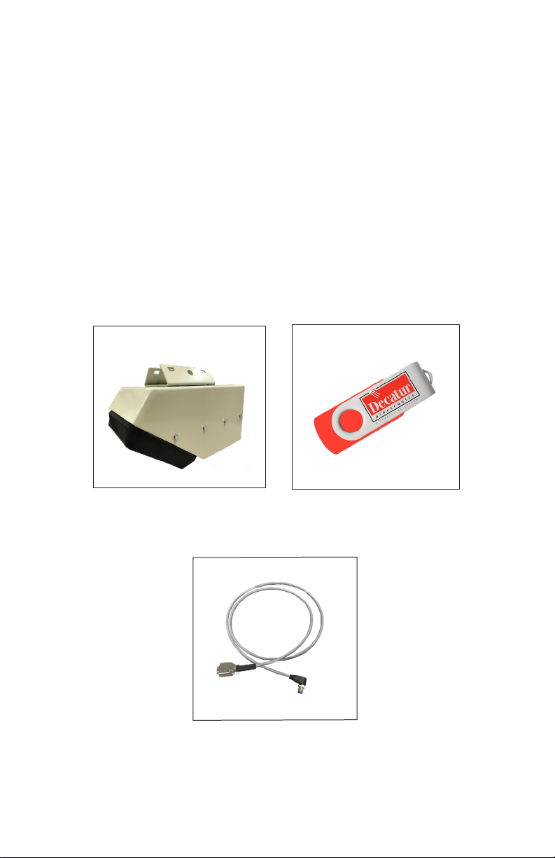
• The package should include the following pictured items along
with this User’s Manual.
SVR Dual™
S769-78613A-0
Serial cable
Flash drive with manual &
software
6
3. Getting Started
3.1 Introduction
The SVR Dual™ is a low prole surface velocity radar specically
designed to measure water velocity and distance and then export
that information as RS232 data via the special serial cable. This allows
the SVR Dual™ to be used for a wide range of water applications.
The SVR Dual™ comes with software on a ash drive that allows the
user to congure certain parameters of the SVR Dual™ for specic
applications. Refer to Section 4 for conguration information.
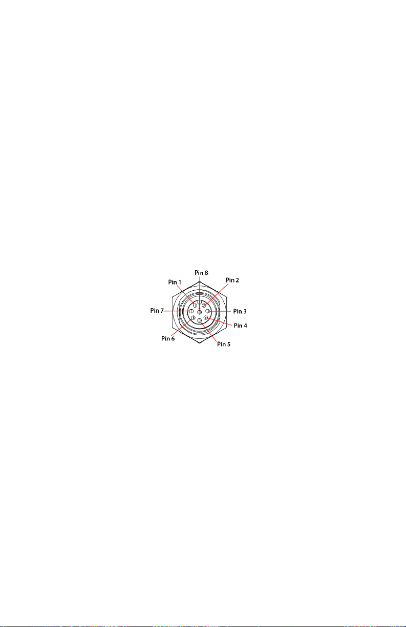
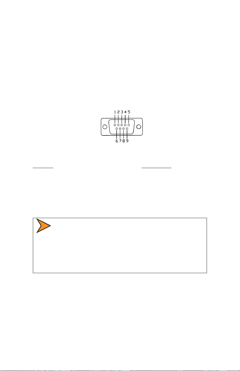
3.2 SVR Dual™ Panel Connector
The SVR Dual™ housing has an 8-pin panel connector which will
receive a variety of cable options. The standard cable is the serial
cable which comes supplied with the SVR Dual™. The 8-pin connector
and it's pin out appears below.
SVR DUAL
™
User’s Manual
Figure 3.2
SVR Dual™ Housing Connector
Pin 1 = Ground
Pin 2 = RS485- or Analog output
Pin 3 = LVL sensor
Pin 4 = SDI-12
Pin 5 = RS485+ or Analog output +
Pin 6 = RS232 TX output from radar
Pin 7 = RS232 RX input to radar
Pin 8 = Power in
7
SVR DUAL
™
User’s Manual
3.3 Connecting the Standard Serial Cable
The SVR Dual™ operates o of +12VDC and comes with a cable that
has two connectors. The circular connector plugs into the SVR Dual™
and the DB-9 serial connector (shown in Figure 3.2b) is used for
powering and communicating with the SVR Dual™. When connecting
the cable it is important to understand that unlike standard RS232
serial connectors that have no +12VDC provisions, the SVR Dual's™
serial connector has two pins dedicated to B+ and ground for the
purpose of powering the unit. Figure 3.3 shows the pin arrangement.
Figure 3.3
Serial Connector
Top Row Bottom Row
Pin 1 = +12VDC (power) Pin 6 = N/C
Pin 2 = RS232 TX / RS485 + Pin 7 = N/C
Pin 3 = RS232 RX / RS485 - Pin 8 = Remote On
Pin 4 = N/C Pin 9 = Ground (power)
Pin 5 = RS232 Ground
RS232 / RS485
• The SVR Dual™ will come set to RS232 or RS485 from
the factory. If the unit is set for RS485 mode, then pins
2&3 above will assume this operation. All other pins are
unchanged.
8
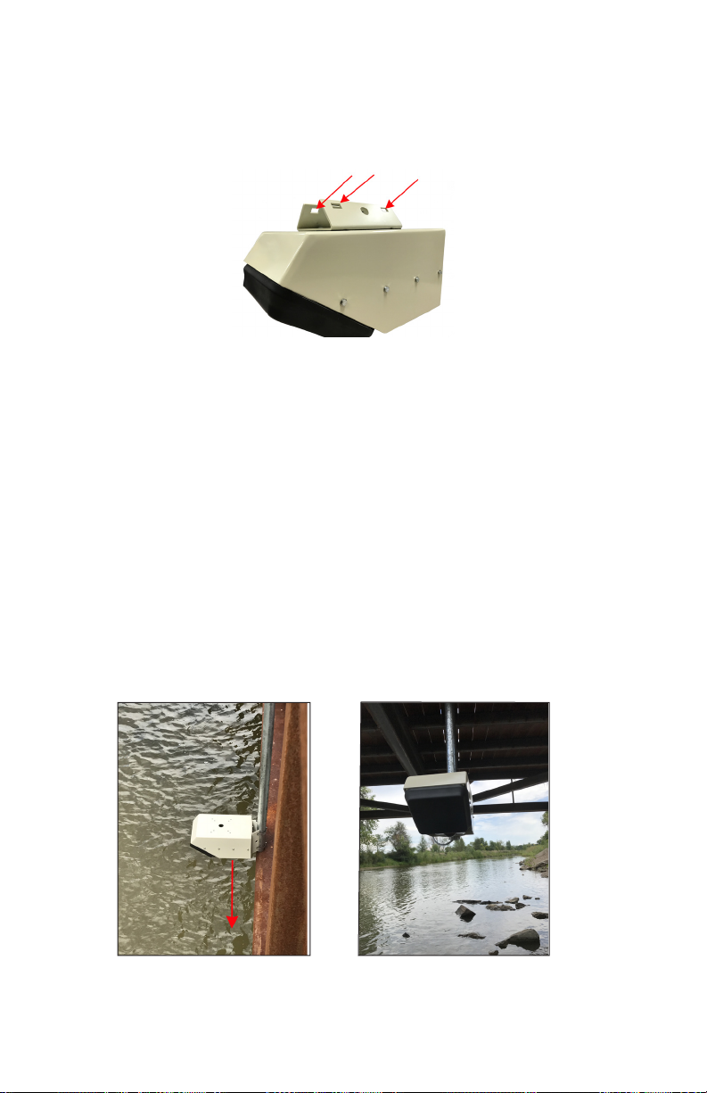
3.4 Mounting Conguration
The SVR Dual™ comes equipped with four mounting holes on the
reverse side (See Figure 3.4). Use these holes only to mount the
SVR Dual™ .
SVR DUAL
™
User’s Manual
Arrows indicatie mounting hole locations.
Figure 3.4
.
The unit can be mounted in a variety of ways using a horizontal or
vertical pipe. The mounting bracket can be attached to the top or
the rear of the unit. The bracket of the unit is then attached to a pipe
using high strength 1/2 inch wide stainless steel adjustable hoops.
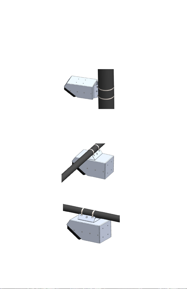
3.5 Mounting Examples
The following examples show standard mounting and positioning of
the SVR Dual™. It is important to make sure that the unit is parallel
with the surface of the water. If need, a level can be placed on the
unit to insure level. In the examples below, a standard pole is used.
SVR parallel to water surface
Figure 3.5a
Figure 3.5b
9
SVR DUAL
™
User’s Manual
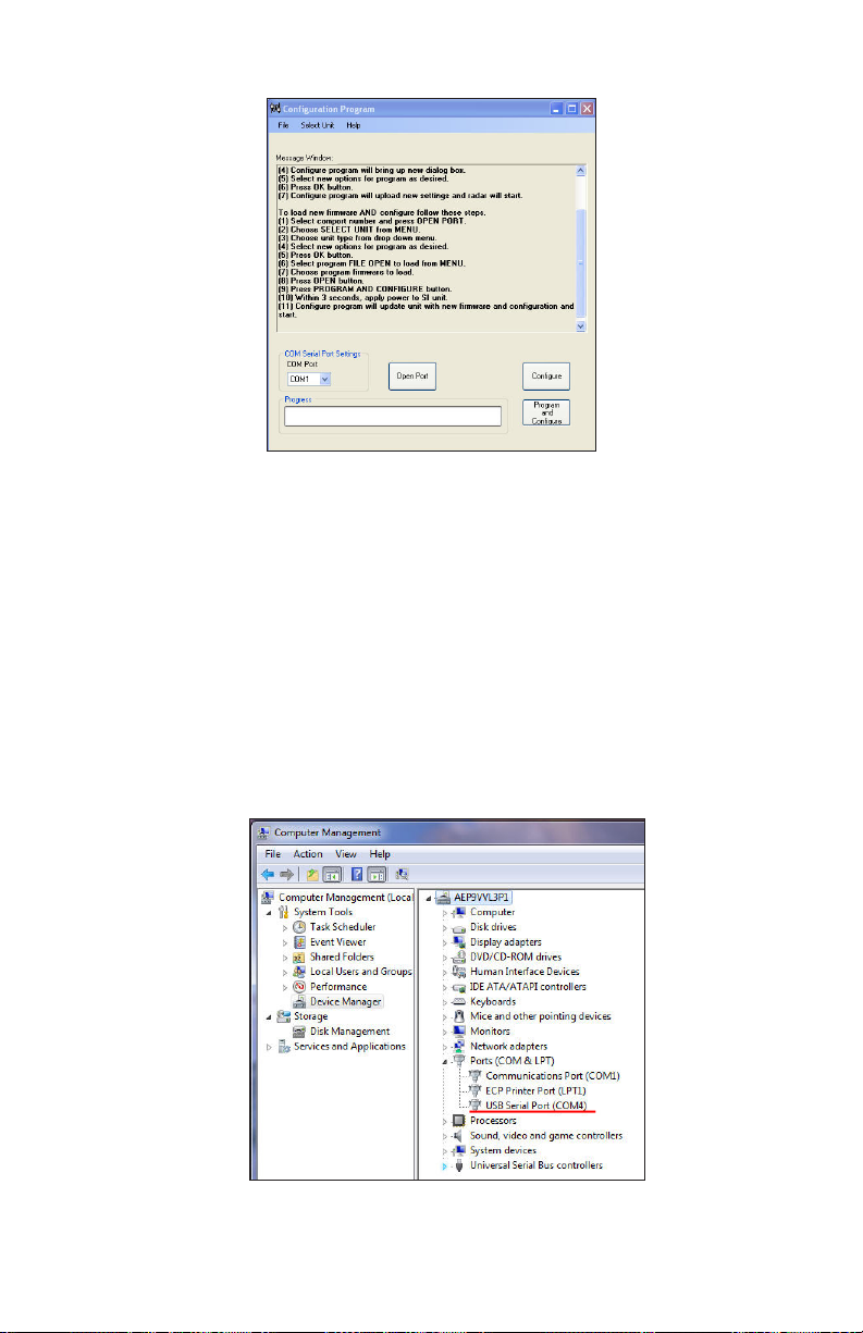
3.6 Mounting Options
Shown below are the various mounting options for the SVR Dual. It
is important to remember that which ever option is chosen that the
SVR Dual be kept parallel with the water surface.
Vertical Mounting Option
Figure 3.6a
Vertical Mounting Option
.
Horizontal Mounting Options
10
Figure 3.6b
Horizontal Mounting Option
.
Figure 3.6c
Horizontal Mounting Option
.

4. Conguring the SVR Dual™
If you are needing to program the SVR Dual™ and it is not yet
connected to a system that will provide the 12 VDC needed to power
it then the S769-78614-0 programming cable may be needed. Refer
to Section 14.2 for more information regarding the cable.
Before proceeding make sure your computer has Microsoft® Net
Framework Version 4.0™ installed. If not, you can install it by going to:
http://msdn.microsoft.com/en-us/netframework/aa569263.aspx.
4.1 Equipment Needed
• SVR Dual™ radar device
• SVR Dual™ serial or programming cable
• PC with either a usable RS232 serial port or a USB-to-RS232
adapter.
• Conguration Program from ash drive
• 12V power supply
4.2 Setup
1. Connect the SVR Dual™ to the programming cable using the end
of the cable that has the red and black wire coming out of it.
SVR DUAL
™
User’s Manual
2. Connect the red wire to the positive (+12 VDC) of the power
supply and connect the black wire to the negative (ground) side
of the power supply. Do not turn the power supply on.
3. Connect the other end of the programming cable to the serial
port of your computer. If you do not have a serial port and are
using a USB to Serial adapter make sure you have installed
the USB to serial adapter software (driver) rst. Then connect
the adapter to the programming cable. Plug the USB to serial
adapter into your computer's USB port.
4.3 Conguration Program Screen
1. Open and run the Conguration program; which is shown in
Figure 4.3a.
11
SVR DUAL
™
User’s Manual
Conguration Program screen
Figure 4.3a
2. The SVR Dual™ Conguration Program is designed to
automatically recognize the assigned USB port. However, if for
some reason it does not recognize the port you can nd what
port has been assigned by checking "Device Manager/ Ports" on
your computer. The port assignment will appear as "USB Serial
Port". Note the port assignment. The example in Figure 4.3b
shows that Port 4 has been assigned. Your port assignment may
be dierent and the port assignment can change the next time
the USB to Serial adapter is plugged in to the computer.
12
Figure 4.3b
Device Manager screen
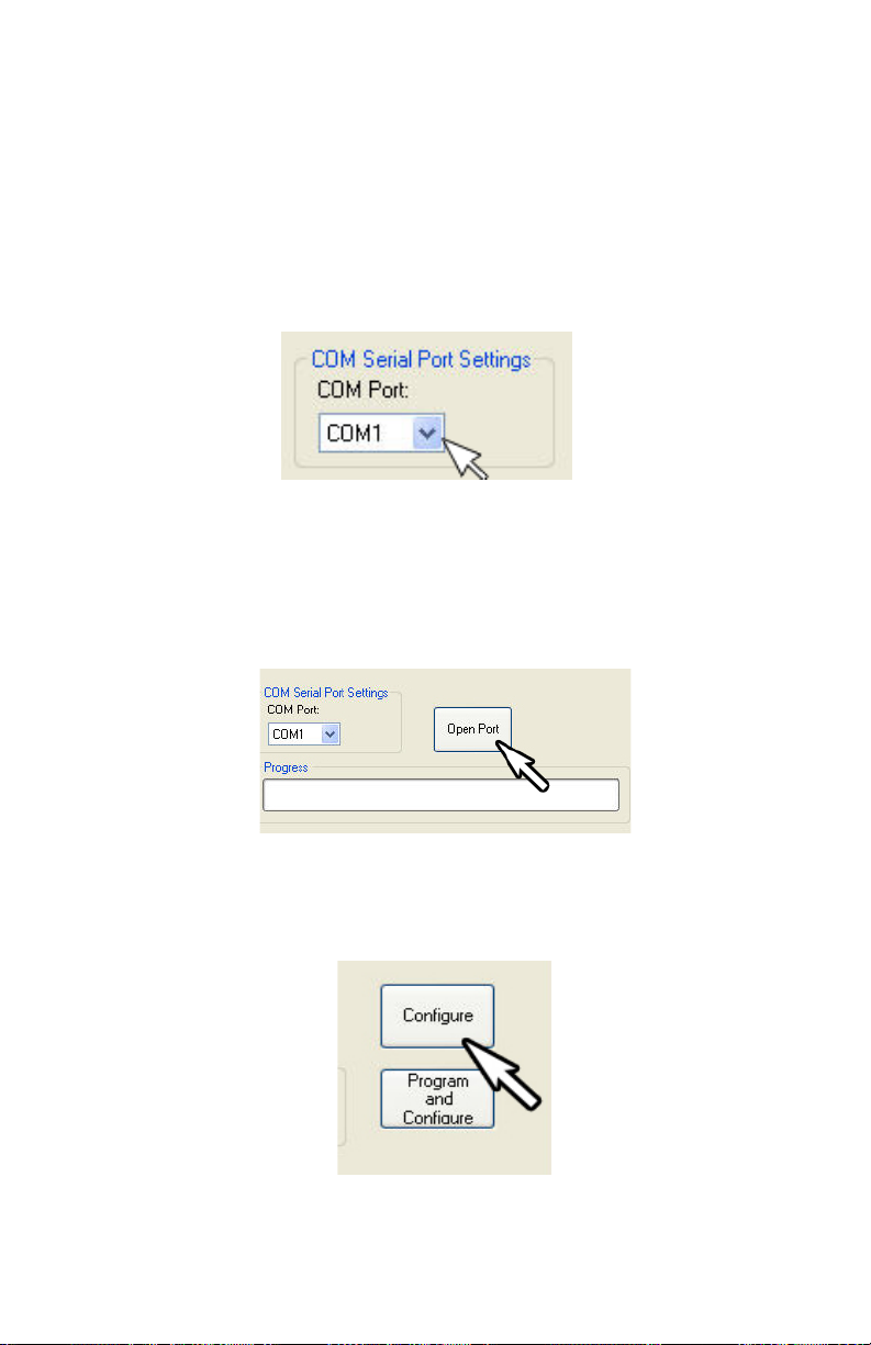
3. From the Conguration Program/Com Serial Port Settings
screen (Figure 4.3c) click on the down arrow and select the COM
port that your PC has assigned. If you are connecting through
the computer's serial port, it will normally be "Com 1" or "Com
2". If you are using the USB to Serial adapter, use the port shown
in Device Manager/Ports. Once the correct port is known, the
Device Manager/Computer Management screens can be closed.
Figure 4.3c
Comm port selection
4. Once the COM port has been selected, left click on the "Open
Port" button. A "COM port OPEN" message will be displayed
indicating that the COM port is now active. (See Figure 4.3d)
SVR DUAL
™
User’s Manual
Figure 4.3d
Press the Open Port button
5. Press the CONFIGURE button. (Figure 4.3e)
Figure 4.3e
Press the CONFIGURE button
13
SVR DUAL
™
User’s Manual
6. Within 3 seconds of pressing the CONFIGURE button, apply
power to the SVR Dual™ unit.
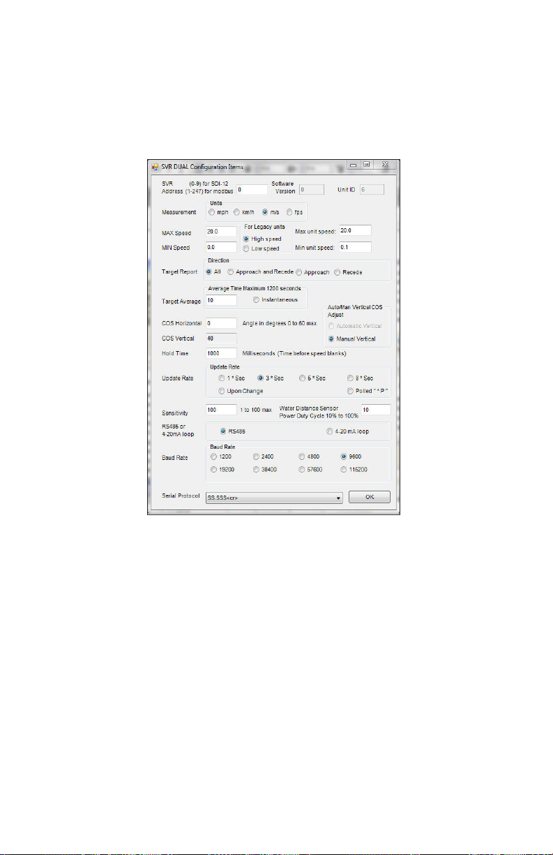
7. The Congure program will bring up the "SVR Dual Conguration
Items" dialog box. (Figure 4.3f)
14
Figure 4.3f
Conguration Items screen
8. Select new options for programming as desired. An explanation
of the settings is described in Section 4.4.
9. Once new options have been selected, press the OK button. The
Congure program will upload the new settings and the SVR
Dual™ will start.
 Loading...