

Decatur Electronics SpeedSpy User Manual & Installation Manual
SpeedSpy
Covert Trac Data Collection
™
User’s Manual &
Installation Guide
Rev 5-1-19

Table of Contents
Welcome to Decatur Electronics ........................................... 6
SpeedSpy™ Features.......................................................7
About this Manual......................................................... 7
1 Receiving Inspection .................................................. 8
2 Setup . . . .............................................................. 8
2.1 Find a Good Location ............................................. 8
2.2 Setting Up the SpeedSpy™ ........................................ 9
3 Components.........................................................11
3.1 Removing the Battery ............................................11
3.2 Installing & Attaching The Battery ................................11
3.3 Battery Charger ..................................................11
3.4 Interconnect Functions ..........................................12
3.5 System Interface (SI-3™) ..........................................13
3.6 EZ Stat™ Module .................................................13
3.7 Tuning Fork Test .................................................13
4 How Radar Works ....................................................15
4.1 Interference Sources and Remedies ..............................15
4.2 Angular Interference (Cosine Eect) ..............................15
4.3 Feedback Interference ...........................................15
5 Specications ........................................................17
6 Legal Requirements ..................................................18
6.1 Document .......................................................18
6.2 FCC Statement...................................................19
6.3 Conditions.......................................................19
6.4 Installer Note ....................................................19
6.5 End User Note ...................................................19
7 EZ Stat™ Data Logger.................................................20
7.1 EZ Stat™ Module .................................................20
7.2 The USB Port.....................................................20
7.3 EZ Stat™ Software Installation ....................................21
8 EZ Stat™ Module .....................................................21
8.1 EZ Stat™ Operation Indicators ....................................21

9. EZ Stat™ Software ....................................................22
9.1 System Requirements............................................22
9.2 Installation ......................................................22
9.3 Logger Setup ....................................................24
9.4 Connection ......................................................25
9.5 Settings .........................................................27
9.6 Log File ..........................................................27
9.7 Generate Report .................................................28
9.8 Generate Charts..................................................30
9.8.1 Count vs. Speed (Bar Graph)...................................30
9.8.2 Count vs. Time (Line Graph) ...................................31
9.8.3 Count vs. Hour (Bar Graph) ....................................32
9.8.4 Trac Speed Survey (Any Graph) ..............................32
10 Frequently Asked Questions ..........................................33
11 Service . .............................................................34
11.1 Warranty .......................................................34
11.2 Service Return Procedure .......................................35
12. Care, Cleaning, and Storage ..........................................36
13. How to Order Additional Products ....................................37

SpeedSpy™ User’s & Installation Manual
Welcome to Decatur Electronics, Inc.
Thank you for choosing the Decatur Electronics SpeedSpy™ — your
solution for covert trac data collection. We urge you to study this
manual before using your SpeedSpy™, so you can maximize all of its
benets, including its sophisticated radar device.
The fact that you purchased a SpeedSpy™ indicates that trac
safety, and ecient trac management in your community are high
priorities.
If you are as pleased with its performance as we think you will be,
ask your Decatur sales representative about other Decatur products;
including the Genesis™ line of radars, the Onsite™ line of speed
trailers, dollies, pole signs, and the Responder™ line of in-car video
systems.
—The Management and Sta at Decatur Electronics,
The Nation’s Oldest Radar Company
4
SpeedSpy™ Features
The Decatur Electronics SpeedSpy™ is an aordable, reliable speed
enforcement tool for stationary mounted data collection.
The SpeedSpy™ features the Decatur Electronics System Interface (SI-
3)™ K-band directional radar antenna, the EZ Stat™ serial module with
statistics software and rugged construction in a weatherproof case.
The SpeedSpy™ is easily installed in multiple applications with the
supplied mounting hardware. Create customized trac speed and
ow reports with the EZ Stat™ software technology.
For more information on other radar/message trailers and signs,
contact us toll-free at 800.428.4315 or visit our web site at;
www.DecaturElectronics.com.
About This Manual
This manual contains valuable information to help you set up, use,
and maintain your SpeedSpy™; so you can optimize its life and keep
it at peak performance. Please take a moment to read through it and
keep it handy for future reference.
SpeedSpy™ User’s & Installation Manual
Note the following symbols in this manual:
Indicates a warning message about safety
precautions. Please read it carefully.
Indicates a helpful tip or precaution to note.
5
SpeedSpy™ User’s & Installation Manual
1. Receiving Inspection
• When you receive your SpeedSpy™, you will want to inspect all
the components for freight damage. Take pictures to document
any damage.
• Notify the freight company immediately of any damage,
preferably while the driver is present.
• Record the damage on the bill of lading and keep a record of the
problems or damage.
• Inspect the SpeedSpy™ for scratches or nicks that might have
happened during shipping.
2. Setup
2.1 Find a Good Location
Position the SpeedSpy™ in a straight line of sight from the motorist’s
view, either before or after a curve and not at a sharp corner (See
Figure 4.2 Angular Interference). The SpeedSpy™ can be mounted on
most roadside poles with the included hardware.
WARNING:
Before proceeding, open the enclosure and remove
any items that are not bolted in place. Remove the 12
VDC battery by unscrewing the three wing nuts from
the battery retaining plate. Disconnect the white
Molex connector. Remove the battery retaining plate
and carefully lift the battery unit with wire harness
completely out of the enclosure. For more on this see
Section 3.1 - Removing the Battery.
6
2.2 Setting Up the SpeedSpy™
Before rst use, plug the charger into a 110 – 120 VAC wall socket
and charge the rst battery by connecting the male/female (white)
Molex™ 2-pos connectors. Refer to the charger manual for further
instructions. After charging the rst battery, disconnect the Molex™
connector and attach the second battery and charge it.
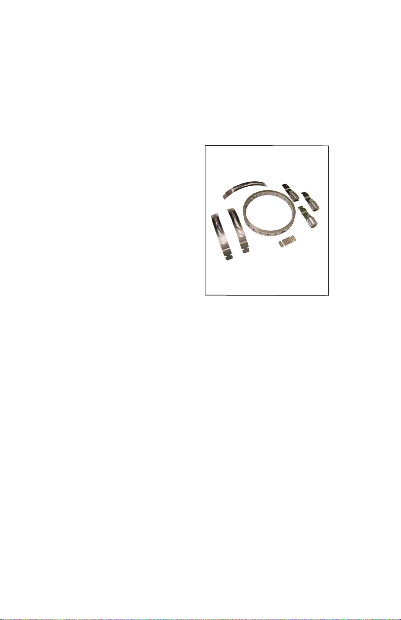
1. The SpeedSpy™
includes an integral
mounting plate
assembly for attaching
to roadside poles.
Use the universal
clamp kit to mount
the SpeedSpy™
bracket to the pole
rst with the security
lock hole facing up.
(Figure 2.2b) Please
refer to the universal
Fig. 2.2a
Universal Clamp Kit
Part Number P085-1
clamp kit package for
instructions for sizing the stainless steel straps.
SpeedSpy™ User’s & Installation Manual
2. Clamp the mounting bracket to a pole. After cutting the straps
to correct length, run each strap through the side strap holes
located on the pole ange of the bracket. Make sure that the
security lock hole is facing up then place the mounting assembly
against the pole (4 -5 ft. from the ground facing trac ow),
position the straps, insert the fasteners and tighten. See Figure
2.2b.
3. Position the SpeedSpy™ enclosure onto the pole mounting
bracket by aligning the four base bolts into the four
corresponding bracket slots. Allow the enclosure to fall into
place. Secure the SpeedSpy™ enclosure by placing the supplied
lock through the security hole on the bracket. See Figure 2.2c
7

SpeedSpy™ User’s & Installation Manual
Figure 2.2b
SpeedSpy Mount
Figure 2.2c
SpeedSpy Lock
4. Unlatch the enclosure door and open. Insert one of the two
12 VDC lead sealed batteries. (See Section 3.1- Removing and
Attaching the Battery for details.)
5. Insert the EZ Stat™ module into the male 9-pin connector.
Reference the red locator label on the enclosure door.
6. Turn on the unit. The power switch is located inside the box.
The unit will operate for approximately two days before the
battery must be recharged. Close and lock the case. The unit is
waterproof only when the case is sealed. Failure to seal the case
may lead to permanent damage to the radar unit.
7. The EZ Stat™ will collect speed data events. The EZ Stat™ reads
vehicle speeds 5 times per second. When a moving object is
detected by the radar, the logger expects it to be present for
at least 4 seconds, then receive a zero speed. The maximum
speed will be recorded with the timestamp in the memory of the
logger module.
NOTE: The EZ Stat™ will not create a record if another car is in range
of the radar before the rst one passes beyond the antenna. When
trac is heavy, there will be no gap (zero speed) in speed readings,
and the EZ Stat™ will see the whole cluster of cars as one event.
8
3. Components
3.1 Removing the Battery
Start by removing the three battery plate wing nuts and the battery
retaining plate. The battery is positioned sideways with the battery
terminals on the right. Stand the enclosure on a at surface with the
battery upright. Next carefully pull the battery from the enclosure.
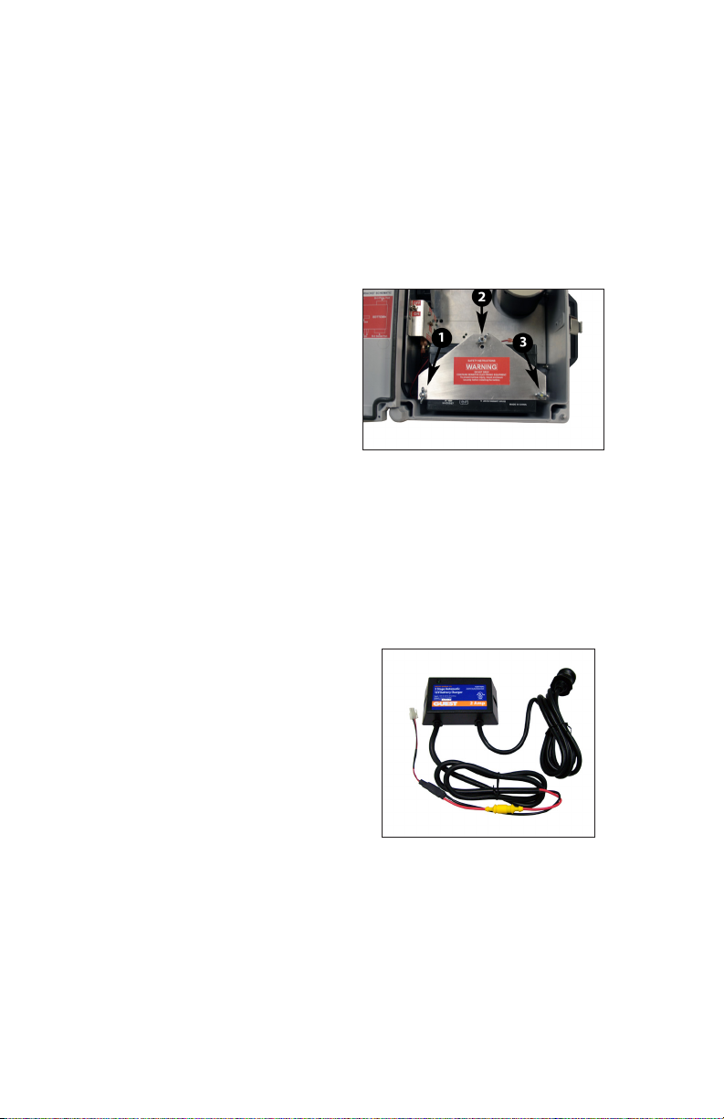
3.2 Installing and Attaching The Battery
Ensure that the three battery
plate wing nuts and battery
retaining plate have been
removed. Stand the enclosure
on a at surface with the
battery cavity upright.
Position the battery sideways
with the battery terminals on
the right and slide/push the
battery back between the guide tubes. Replace the battery retaining
plate and secure using the three wing nuts. Tighten the wing nuts
enough to secure the battery and prevent movement. Connect the
male/female white colored Molex™ connectors.
Figure 3.2
Wing nut locations
SpeedSpy™ User’s & Installation Manual
3.3 Battery Charger
The charger is designed
for mounting. However we
recommend that you use it
as a desktop device. Charge
the batteries at the oce to
minimize having to remove
the SpeedSpy™ enclosure. If
required, the charger can be
mounted to the SpeedSpy™
Figure 3.3
Battery Charger
S702-39
base plate and attached to the
optional charger connections on
the interconnect circuit board (See Figure 3.4). The battery charger
has a 5 A fuse.
9
SpeedSpy™ User’s & Installation Manual
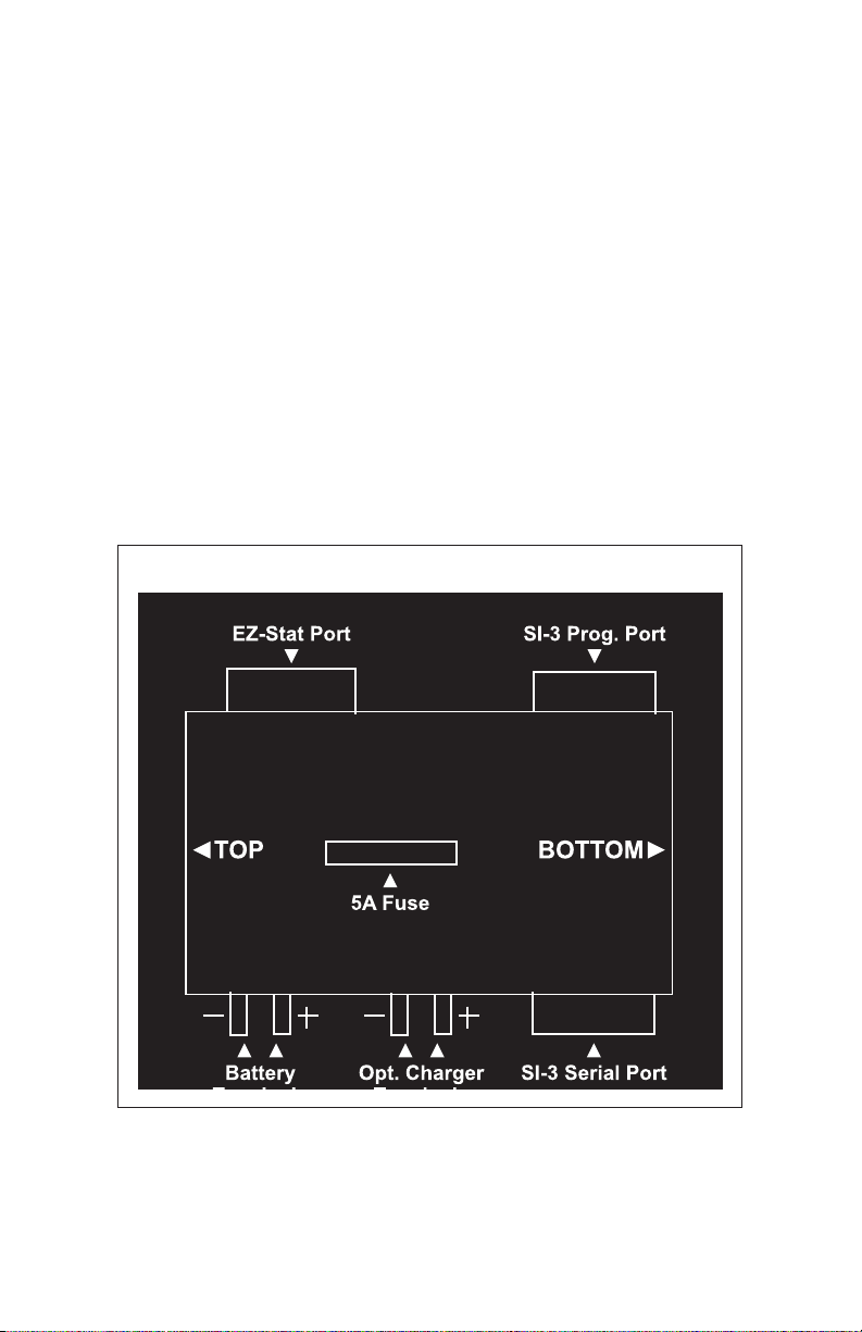
3.4 Interconnect Functions
Fig. 3.4 details the three interface communication ports which
transfers radar data from the SI-3™ antenna assembly to the EZ Stat™
and the SI-3™ programming port.
• ON/OFF: Flip the toggle switch to power on/o.
• SI-3 Prog. Port: The female 9-pin connector is used to access the
SI-3™ programming options.
• EZ Stat Port: The male 9-pin connector is used to attach the EZ
Stat™ module used to collect trac data.
• SI Serial Port: SI-3™ is connected to this port/connector.
• Battery/Opt. Charger Terminals: plus (+) = red, minus ( - ) = black.
INTERFACE BRACKET SCHEMATIC
10
Figure. 3.4
Port Locations
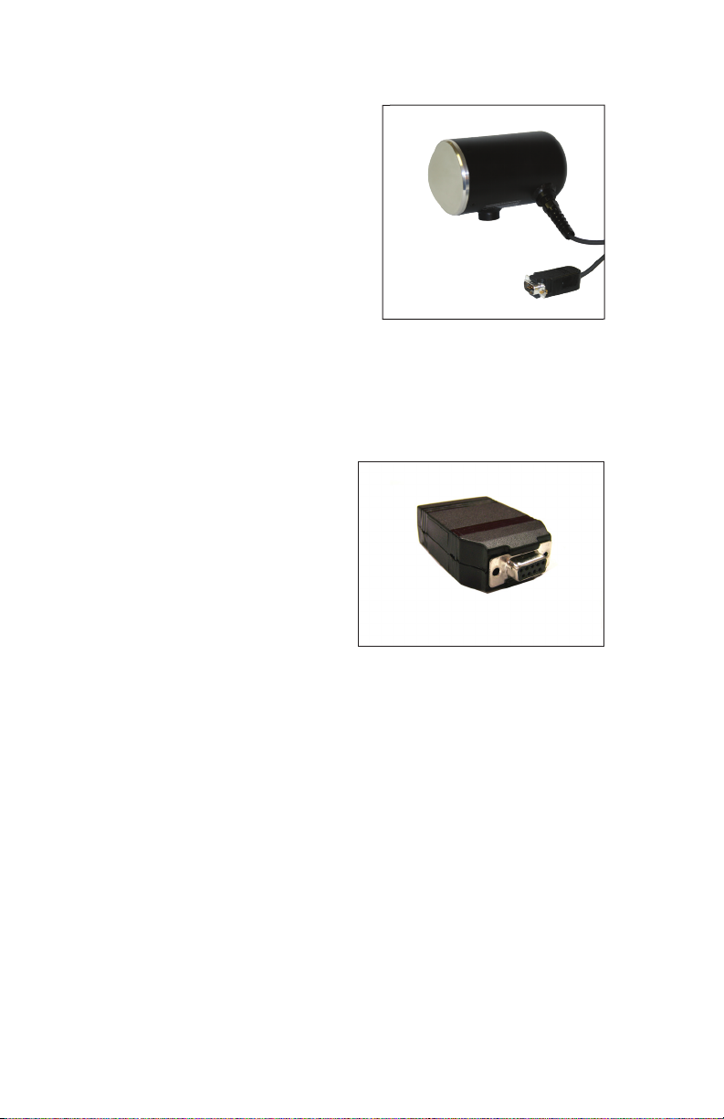
3.5 System Interface (SI-3)™
The SpeedSpy™ features the
Decatur Electronics System
Interface (SI-3)™ directional
radar—a high-performance
radar system that comes
congured to monitor only
the trac that is approaching
the radar antenna. Radar
sensitivity has been pre-set for
optimal operations. Fog, heavy
rain, snow, and blowing dust
can reduce the speed detection range.
3.6 EZ Stat™ Module
The SpeedSpy™ includes
an EZ Stat™ module and
the software application for
trac data collection.
SpeedSpy™ User’s & Installation Manual
Figure 3.5
SI-3™ Antenna
Figure 3.6
EZ Stat™ module
3.7 Tuning Fork Test
If the SpeedSpy™ has come equiped with a tuning fork then the fork
can be used to verify that the logger is receiving speed data.
To begin the test, make sure the SpeedSpy™ is turned on and that
the EZ Stat™ data logger is plugged in. The green LED on the EZ Stat
will be blinking. There is 60 seconds from the time the SpeedSpy™ is
turned on in which to perform the test. After 60 seconds the system
would need to be turned o and back on if the test is to be repeated.
1. Tap the tines of the fork on a rm, non-metallic surface. The
tuning fork will ring audibly. Then place the tuning fork that you
11
 Loading...