

Decatur Electronics GHD, Scout User Manual

GHD
™
Scout
™
User’s Manual
Canada Variant • Rev 25/Aug/2010

GHD
™
Scout
™
User’s Manual
Canada Variant • Rev 25/Aug/2010
This manual is the most current version
and supersedes all other manuals.

Table of Contents
Welcome to Decatur Electronics . . . . . . . . . . . . . . . . . . . . . . . . . . . . . . . . . . . . . . . . . . . 6
About This Manual . . . . . . . . . . . . . . . . . . . . . . . . . . . . . . . . . . . . . . . . . . . . . . . . . . . . . . . . 7
1 Safety Information . . . . . . . . . . . . . . . . . . . . . . . . . . . . . . . . . . . . . . . . . . . . . . . . . . . . 7
2 Receiving Inspection . . . . . . . . . . . . . . . . . . . . . . . . . . . . . . . . . . . . . . . . . . . . . . . . . . 9
3 Getting Started . . . . . . . . . . . . . . . . . . . . . . . . . . . . . . . . . . . . . . . . . . . . . . . . . . . . . . 10
3.1 Introduction . . . . . . . . . . . . . . . . . . . . . . . . . . . . . . . . . . . . . . . . . . . . . . . . . . . . .10
3.2 Battery Charging - SCOUT . . . . . . . . . . . . . . . . . . . . . . . . . . . . . . . . . . . . . . . .10
3.3 Removing The Battery Holder - SCOUT. . . . . . . . . . . . . . . . . . . . . . . . . . . . 10
3.4 Battery Installation. . . . . . . . . . . . . . . . . . . . . . . . . . . . . . . . . . . . . . . . . . . . . . . 11
3.5 Inserting The Holder Into The SCOUT . . . . . . . . . . . . . . . . . . . . . . . . . . . . . 11
3.6 Charging The Batteries - SCOUT . . . . . . . . . . . . . . . . . . . . . . . . . . . . . . . . . . 12
3.7 Charging Status Indicator (LED) SCOUT . . . . . . . . . . . . . . . . . . . . . . . . . . .13
3.8 Battery Run Time - SCOUT . . . . . . . . . . . . . . . . . . . . . . . . . . . . . . . . . . . . . . . . 14
3.9 Replacing Batteries - SCOUT . . . . . . . . . . . . . . . . . . . . . . . . . . . . . . . . . . . . . 14
3.10 Connecting The Power Cord - SCOUT . . . . . . . . . . . . . . . . . . . . . . . . . . 14
3.11 Plug In The Power Cord - GHD & SCOUT . . . . . . . . . . . . . . . . . . . . . . . . 15
3.12 Control Panel Functions . . . . . . . . . . . . . . . . . . . . . . . . . . . . . . . . . . . . . . . 15
3.13 Measuring Target Speed In Faster Vehicle Mode. . . . . . . . . . . . . . . . . 15
4 Components - GHD & SCOUT . . . . . . . . . . . . . . . . . . . . . . . . . . . . . . . . . . . . . . . . . 16
4.1 Control Buttons. . . . . . . . . . . . . . . . . . . . . . . . . . . . . . . . . . . . . . . . . . . . . . . . . . 16
4.2 Display . . . . . . . . . . . . . . . . . . . . . . . . . . . . . . . . . . . . . . . . . . . . . . . . . . . . . . . . . . 17
4.2.1 Number Segments. . . . . . . . . . . . . . . . . . . . . . . . . . . . . . . . . . . . . . . . . . . . . 17
4.2.2 Status Indicator Icons . . . . . . . . . . . . . . . . . . . . . . . . . . . . . . . . . . . . . . . . . . 17
4.3 Trigger . . . . . . . . . . . . . . . . . . . . . . . . . . . . . . . . . . . . . . . . . . . . . . . . . . . . . . . . . . 18
4.4 Mounting Conguration . . . . . . . . . . . . . . . . . . . . . . . . . . . . . . . . . . . . . . . . . 18
5 Operating Modes . . . . . . . . . . . . . . . . . . . . . . . . . . . . . . . . . . . . . . . . . . . . . . . . . . . . 19
5.1 Menu. . . . . . . . . . . . . . . . . . . . . . . . . . . . . . . . . . . . . . . . . . . . . . . . . . . . . . . . . . . . 19
5.2 Directional. . . . . . . . . . . . . . . . . . . . . . . . . . . . . . . . . . . . . . . . . . . . . . . . . . . . . . . 22
5.3 Strongest Signal Mode. . . . . . . . . . . . . . . . . . . . . . . . . . . . . . . . . . . . . . . . . . . 23
5.4 Faster Mode . . . . . . . . . . . . . . . . . . . . . . . . . . . . . . . . . . . . . . . . . . . . . . . . . . . . . 23
5.5 Faster-Toggle Mode. . . . . . . . . . . . . . . . . . . . . . . . . . . . . . . . . . . . . . . . . . . . . . 23
5.6 Faster-Hold Mode . . . . . . . . . . . . . . . . . . . . . . . . . . . . . . . . . . . . . . . . . . . . . . . . 24
6 Serial Output Mode . . . . . . . . . . . . . . . . . . . . . . . . . . . . . . . . . . . . . . . . . . . . . . . . . . 25
7 Performance Tips . . . . . . . . . . . . . . . . . . . . . . . . . . . . . . . . . . . . . . . . . . . . . . . . . . . . 25
7.1 How Radar Works . . . . . . . . . . . . . . . . . . . . . . . . . . . . . . . . . . . . . . . . . . . . . . . . 25
7.2 Interference Sources . . . . . . . . . . . . . . . . . . . . . . . . . . . . . . . . . . . . . . . . . . . . . 25
7.2.1 Angular Interference (Cosine Error Eect). . . . . . . . . . . . . . . . . . . . . . . 26
7.2.2 Fan Inteference. . . . . . . . . . . . . . . . . . . . . . . . . . . . . . . . . . . . . . . . . . . . . . . . 27
7.2.3 Electromagnetic Interference (EMI) . . . . . . . . . . . . . . . . . . . . . . . . . . . . . 27
7.2.4 Feedback Interference . . . . . . . . . . . . . . . . . . . . . . . . . . . . . . . . . . . . . . . . . 27
7.2.5 Multi-Path Beam Cancellation . . . . . . . . . . . . . . . . . . . . . . . . . . . . . . . . . . 28
7.2.6 Radio Frequency Interference (RFI) . . . . . . . . . . . . . . . . . . . . . . . . . . . . . 28
7.2.7 Scanning . . . . . . . . . . . . . . . . . . . . . . . . . . . . . . . . . . . . . . . . . . . . . . . . . . . . . . 28
7.2.8 Vehicle Ignition Interference). . . . . . . . . . . . . . . . . . . . . . . . . . . . . . . . . . . 28
8 Testing The Device . . . . . . . . . . . . . . . . . . . . . . . . . . . . . . . . . . . . . . . . . . . . . . . . . . . 29
8.1 Operator-Requested Self Test. . . . . . . . . . . . . . . . . . . . . . . . . . . . . . . . . . . . . 29
8.2 Mini-Test . . . . . . . . . . . . . . . . . . . . . . . . . . . . . . . . . . . . . . . . . . . . . . . . . . . . . . . . 29
9 Care, Cleaning, and Storage . . . . . . . . . . . . . . . . . . . . . . . . . . . . . . . . . . . . . . . . . 30
10 Specications . . . . . . . . . . . . . . . . . . . . . . . . . . . . . . . . . . . . . . . . . . . . . . . . . . . . . . . . 30
10.1 Antenna Parameters K-Band . . . . . . . . . . . . . . . . . . . . . . . . . . . . . . . . . . . 30
10.2 Environment . . . . . . . . . . . . . . . . . . . . . . . . . . . . . . . . . . . . . . . . . . . . . . . . . . 30
10.3 Speed Range Parameters. . . . . . . . . . . . . . . . . . . . . . . . . . . . . . . . . . . . . . . 30
10.4 Power Consumption Parameters . . . . . . . . . . . . . . . . . . . . . . . . . . . . . . . 30
10.5 Accuracy . . . . . . . . . . . . . . . . . . . . . . . . . . . . . . . . . . . . . . . . . . . . . . . . . . . . . . 31
11 Legal Requirements . . . . . . . . . . . . . . . . . . . . . . . . . . . . . . . . . . . . . . . . . . . . . . . . . . 32
11.1 FCC . . . . . . . . . . . . . . . . . . . . . . . . . . . . . . . . . . . . . . . . . . . . . . . . . . . . . . . . . . . 32
12 Frequently Asked Questions (FAQ) . . . . . . . . . . . . . . . . . . . . . . . . . . . . . . . . . . . . 33
13 Warranty. . . . . . . . . . . . . . . . . . . . . . . . . . . . . . . . . . . . . . . . . . . . . . . . . . . . . . . . . . . . . 34
14 Service Return Procedure. . . . . . . . . . . . . . . . . . . . . . . . . . . . . . . . . . . . . . . . . . . . . 35
15 How to Order Additional Products . . . . . . . . . . . . . . . . . . . . . . . . . . . . . . . . . . . . 37
16 Communications Port . . . . . . . . . . . . . . . . . . . . . . . . . . . . . . . . . . . . . . . . . . . . . . . . 37
17 User Notes . . . . . . . . . . . . . . . . . . . . . . . . . . . . . . . . . . . . . . . . . . . . . . . . . . . . . . . . . . . 38
GHD
™
& Scout
™
User’s Manual
GHD
™
& Scout
™
User’s Manual
6
25/Aug/2010
Welcome to Decatur Electronics, Inc.
Thank you for choosing this Decatur Electronics product — A highly
advanced trac radar unit that will reward your department with
years of dependable service. Both the Genesis Handheld Directional
(GHD)™ and Scout™ incorporate high performance and long range,
with many leading features. We urge you to study this manual
before using the GHD or Scout so you can maximize the benets of
this sophisticated radar device. We believe you will be pleasantly
surprised by the features and advantages.
If you are as pleased with its performance as we think you will be,
ask your Decatur sales representative about other Decatur products
including the Genesis™ line of radars, the Onsite™ line of speed
trailers, dollies, and pole signs and the Responder™ line of in-car
video systems.
Trac ocers told us exactly what they wanted in a radar device and we built it. Try any one of our products and see if you don't agree
that it is the best-in-class!
—The Management and Sta at Decatur Electronics,
The Nation’s Oldest Radar Company
About This Manual
This manual contains valuable information to help you set up, use
and maintain your radar, so you can extend its life and keep it at peak
performance. Please take a moment to read through it, and keep it
handy for future reference.
Note the following symbols in this manual:
Indicates a warning message about safety
precautions. Please read it carefully.
Indicates a helpful tip or precaution to note.
1. Safety Information
All service needs should be referred back to the manufacturer or to
your local authorized service center.
WARNING
• Do not over voltage the radar - it can damage the unit!
See notes.
• When replacing batteries in the SCOUT you should
replace all 6 with new batteries even if you suspect that
only one cell is defective.
• Use rechargeable Nickle-Metal-Hydride batteries only.
• The GHD and the SCOUT are designed to operate o
of conventional +12 VDC (10.8 to 16.5 VDC) from their
power cables. In addition the SCOUT is also designed
to operate at 7.2VDC from the internal batteries. Over
voltage to the power cables or incorrect batteries can
cause damage.
25/Aug/2010
7
GHD
™
& Scout
™
User’s Manual
GHD
™
& Scout
™
User’s Manual
8
25/Aug/2010
• Opening the GHD or the SCOUT (other than battery
replacement) automatically voids any warranty still in
eect. There are no user serviceable parts inside.
• Do not expose the GHD or the SCOUT to excessive
moisture. Never submerge the device. Violation of these
guidelines may void the warranty.
• Do not drop the GHD or the SCOUT on hard surfaces
since damage could occur. Units damaged by dropping
or abuse are not covered for warranty repair.
2. Receiving Inspection
When you receive your radar, inspect all components for freight
damage that might have happened during shipping or unloading.
• Notify the freight company immediately of any damage,
preferably while the driver is present.
• Record the damage on the bill of lading and keep a record of the
problems or damage.
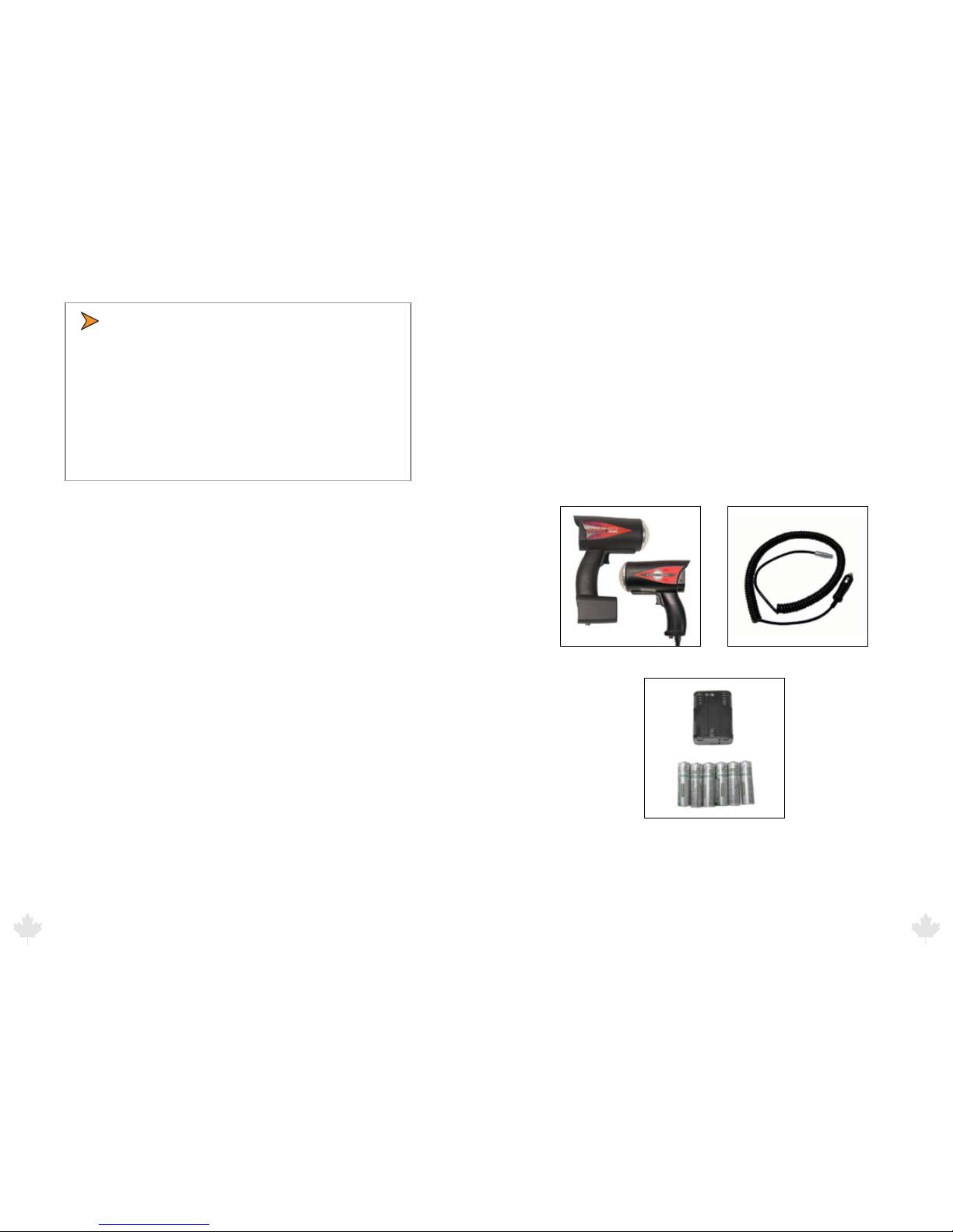
• The package should include the following pictured items along
with this User’s Manual.
Scout or GHD Radar Detachable Power Cable (Scout)
Batteries/Battery Holder (Scout)
25/Aug/2010
9
GHD
™
& Scout
™
User’s Manual
GHD
™
& Scout
™
User’s Manual
10
25/Aug/2010
3. Getting Started
3.1 Introduction
The GHD and SCOUT are stationary radars that give you the option
to track vehicles approaching, receding, or moving in both directions
simultaneously. Directionality dramatically enhances the target
selection process. For example, if the radar is set in toward (t) mode,
it will track only vehicles coming toward the radar and ignore all
vehicles moving away from it! In heavy trac situations, you can
choose to make trac moving in either direction invisible to the
radar.
3.2 Battery Charging - SCOUT
The SCOUT is designed to operate o of six (6) rechargeable NickelMetal-Hydride batteries (or o the DC power cord). When you rst
receive your radar, the batteries will need to be charged for the rst
time before using. Once batteries have been charged if you do not
use the SCOUT for 3-4 weeks, you will want to recharge the batteries
before use in order to get the full run time. To charge batteries for the
rst time or to replace the batteries following steps 3.6 to 3.7.
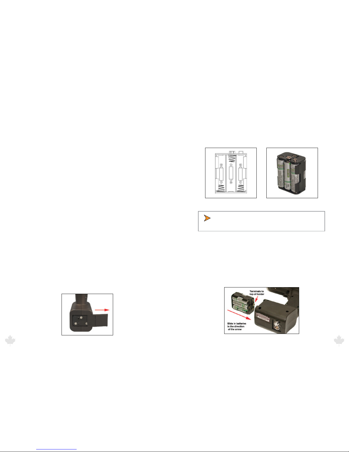
3.3 Removing the Battery Holder -SCOUT
The battery holder is located inside the handle of the SCOUT and is
accessed by means of a sliding door. When rst received, the holder
should already have batteries installed, but if not then you will need
to remove the holder and loaded it with batteries. To remove the
battery holder slide the battery cover to the right until the battery
holder is released as shown in Figure 3.3. The door can be completely
removed from the slide.
Figure 3.3
3.4 Battery Installation - SCOUT
Insert the batteries into the battery holder following the polarity
guide that is on the inside of the battery holder (Figure 3.4a.) Once
properly loaded the battery holder will look like the example in
Figure 3.4b
Figure 3.4a Figure 3.4b
• Note that the negative side of each battery goes to the
spring contacts of the battery holder.
3.5 Inserting the Holder into the SCOUT
The battery holder is designed so that it can only make contact with
the power connections inside the gun if the holder is slid into the
gun in the correct way. If you look closely at the holder you will see
that there is a positive and negative terminal on it. These need to be
inserted into the gun with the terminals located at the top as shown
in the picture below.
Figure 3.5
25/Aug/2010
11
GHD
™
& Scout
™
User’s Manual
GHD
™
& Scout
™
User’s Manual
12
25/Aug/2010
Once the batteries have been properly loaded into the holder and
the holder has been inserted into the handle of the gun then the
door can be put back in place and slid closed. If you have not already
charged the batteries using an optional NiMH charger, you are now
ready to charge the batteries using the power cable.
• If the holder has been placed incorrectly into the
handle the door can not be put back in place and
closed..
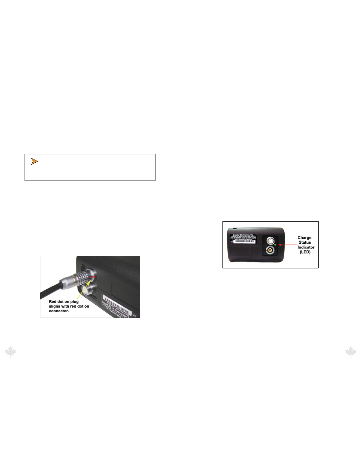
3.6 Charging the Batteries - SCOUT
The power cable that comes with the SCOUT can be used to either
power the SCOUT directly from your vehicle receptacle or to charge
the SCOUT’s batteries. Once the batteries have been properly
installed into the holder and inserted into the handle plug the
power cord into the power connector at the base of the handle by
aligning the red dot on the power cord’s plug with the red dot on
the connector (See Figure 3.6). Failure to align the plug with the
connector properly will result in damage to the pins of the jack.
Figure 3.6
Next, plug the lighter plug into an active cigarette lighter receptacle
in the vehicle. The red led on the lighter plug should come on
showing that power is being applied to the SCOUT. With the SCOUT
turned o, it will take approximately 2 hours to fully charge the
batteries. Turning the SCOUT on with the cord plugged in will stop
the charge cycle allowing the gun to be operated from the power
cord. Batteries do not charge when the gun is turned on.
3.7 Charge Status Indicator (LED) - SCOUT
The status of the charge can be determined by the Charge Status
Indicator LED located on the bottom of the handle (See gure 3.7).
The table below denes the status.
• Fast blinking green light = checking battery condition
• Medium blinking green light = charging battery
• Solid green light = charged
• Solid red light = charging error
Figure 3.7
The normal charging sequence is fast blink for 60 seconds, medium
blink until batteries are fully charged (approximately 2 hours for fully
discharged batteries) and solid green once batteries are charged.
The gun can be left to charge indenitely. The charging circuit will
automatically shut o once charging is complete.
25/Aug/2010
13
 Loading...