

DecaLED 95312351 User Manual
DecaLED® High Power DMX
Controller TV
95312351
Manual
Description
The DecaLED® High Power DMX Controller TV offers a solution for controlling all dimmable 1 Watt Power LED
products. The DecaLED® High Power DMX Controller TV is also ideally suited to use in TV studios, as it causes no
interference to cameras.
Package contents
1 x DecaLED High Power DMX Controller TV
1 x Manual
Carefully unpack the carton. Check the contents to ensure
that all parts are present and have been received in good
condition. If any parts appear damaged or missing, notify
the shipper immediately and retain packing material for
inspection. In the event that the xture must be returned to
the factory, it is important that the xture is returned in the
original factory box and packaging.
Safety Instruction
The ground connection should be essential for this unit.•
Donotmakeanyinammableliquids,waterormetalobjectsentertheunit.•
Topreventorreducetheriskofelectricshock,donotopenthetopcover.•
Thisunitmustbeoperatedbyadults,tonotallowchildrentoplaywithit.•
There are no user serviceable parts inside this unit. Do not attempt any repairs yourself.•
Shouldyouexperienceanyproblemduringuse,pleasecontactyourlocaldealerimmediately.•
Donotdiscardtheshippingcartoninthetrash.Pleaserecyclewheneverpossible.•
Alwaysconsultauthorizedpersonellforanyrepairsandmaintenance.•
Features
USITT Standard DMX-512 (1990) multiplexed digital control, via 3-pin XLR connector and terminals.•
DMX Control Mode and Stand Alone Mode available.•
1~7 patterns plus a sequence of 7 patterns, chase speed and fade time adjustable.•
Different Ouput Group modes for user assignable.•
Output loading modes available in RGB mode, WHITE mode and COOL WHITE & WARM WHITE mode.•
Manual Dim mode allows to control overall output intensity.•
Full range voltage of AC 110-120V / AC 220-240V power input option by voltage selector.•
Providing built-in DC24V 6.5A / 48V 3.2A PSU.•
Power Failure Memory.•
Installation
Connectingthepowersupply
Before plugging your unit in, be sure the voltage in your area matches the required voltage for you The
DecaLED® High Power DMX Controller TV power supply. The DecaLED® High Power DMX Controller TV is
available in a 120V and 230V version. Due to variations in line voltage from venue to venue, be sure to plug
your power supply into a wall outlet with matching power before attempting to operate.
Datacable(DMXcable)requirements
Connect the DecaLED® High Power DMX Controller TV and you xtures using standard 3-pin DMX cables. The
DecaLED® High Power DMX Controller TV uses the DMX-512 protocol to operate your xtures.
0 = OFF 1 = ON
000
100
010
110
001
101
011
1110%100%
1
2
3
ON
FADE TIME
000
100
010
110
001
101
011
111
0.1S
0.2S
0.5S
1S
5S
10S
20S
30S
4
5
6
ON
SPEED
000
100
010
110
001
101
011
111
1
2
3
4
5
6
7
AUTO
7 8
9
ON
PROGRAM
(Dip Switches 10 = off)
STAND ALONE
............
1 2 3 4 5 6 7 8 9 10
ON RS
1,2,4
3,4
1,3,4
2,3,4
1,2,3,4
1,2,3,4,5,6,7,8,9
1
2
1,2
3
1,3
2,3
1,2,3
4
1,4
2,4
DMX ADDRESS (SLAVE)
SWITCHES ON SWITCHES ON
(Dip Switches 10 = on)
START
CH#
START
CH#
1
2
3
4
5
6
7
8
9
10
11
12
13
14
15
..
511
..
..
..
..
..
..
..
1 2 3 4 5 6 7 8 9 10
ON RS
MODE OUTPUT
00 1 Group
10 2 Group
01 3 Group
11 6 Group
OUTPUT TERMINALS
4
5
1 =ON
0=OFF
1
2
1 =ON
0=OFF
00 RGB
10 White
01 White & Warm
11 RGB
1
Red +
White +
+
Red +
Warm White
2
Red -
White -
Warm White -
Red -
3
Green +
White +
White +
Green +
4
Green -
White -
White -
Green -
5
Blue +
White +
Warm White +
Blue +
6
Blue -
White -
Warm White -
Blue -
123456
www.decaled.com
Product code:
High Power DMX Controller TV
95312351
Product code: 95312351
High Power DMX Controller TV
If you want to construct your own data cables, be sture to use standard two conductor shielded cable (this
cable may be purchased at almost all professional sound and lighting stores). Your cables should be made
with a 3-pin male and female XLR connector on either end of the cable. Also remember that DMX lines must
be daisy chained and can not be split.
Be sure to follow the gures 2 and 3 below when making your own cables. Do not use the ground lug on the
XLR connector. Do not connect the cable’s shield conductor to the ground lug or allow the shield conductor
to come in contact with the XLR’s out casing. Grounding the shield could case a short circuit and erratic
behavior.
Special note: Line termination
When longer runs of cable are used, you may need to use a terminator on the last unit to avoid erratic
behavior. A terminator is a 120 Ohm 1/4W resistor which is connected to pins 2 and 3 of a male XLR connector
(DATA+ and DATA-). This unit is inserted in the female XLR connector of the last unit in your daisy chain to
terminate the line. Using a cable terminator will decrease the possibilities of erratic behavior.
5-pin XLR DMX connectors
Some manufacturers use 5-pin XLR connector for DATA transmission in place of 3-pin. 5-pin XLR xtures may be
implemented in a 3-pin XLR DMX line. When inserting standard 5-pin XLR connectors in to a 3-pin line a cable
adaptor must be used, these adaptors are readily available at most electric stores. The chart below details a
proper cable conversion:
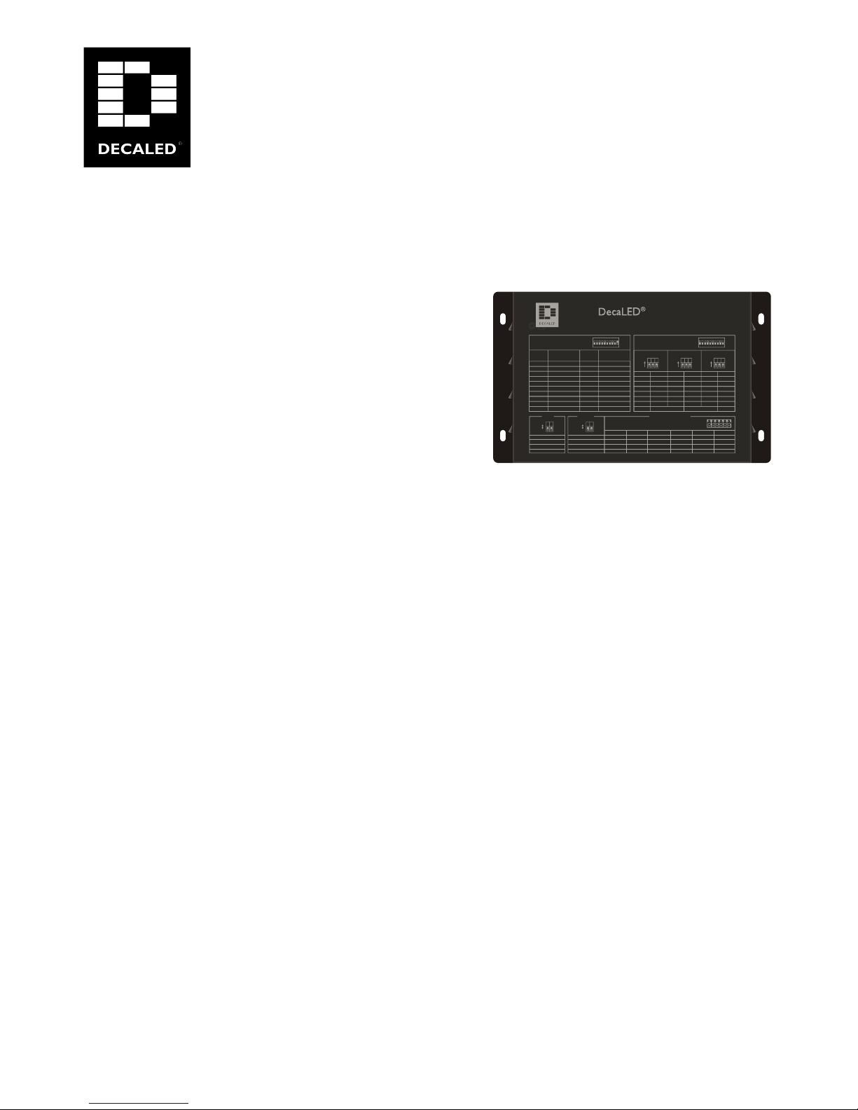
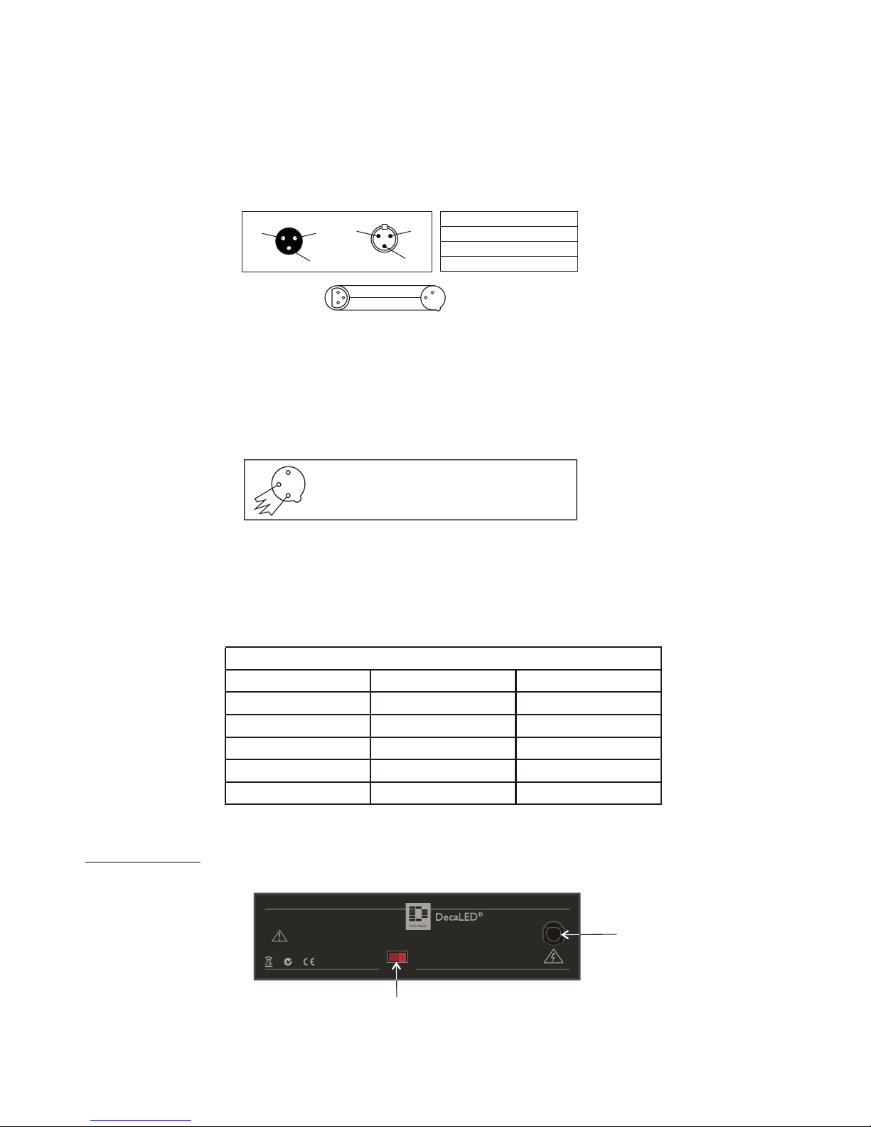
Controls and functions
Rear panel layout
Power input: AC100~120V (3.2A) / AC220~240V (1.2A), 50~60Hz1.
Voltage selector: AC120V/230V optional by this voltage selector2.
Figure 1
Controller TV is a HP LED control unit, specially used to drive 1 Watt high power LED
AC 110-120V/AC220-240V power input option by voltage selector.
Figure 2
Figure 3
XLR Male Socket
1 Ground 2 Cold
3 Hot
XLR Female Socket
3 Hot
2 Cold
1 Ground
XLR Pin Configuration
Pin 1 = Ground
Pin 2 = Data Compliment (negative)
Pin 3 = Data True (positive)
DMX 512 OUT
3-PIN XLR
1
2
3
1
2
3
DMX 512 IN
3-PIN XLR
Termination reduces signal errors and avoids signal transmission
problems and interference. It is always advisable to connect a
DMX terminal, (Resistance 120 Ohm 1/4 W) between PIN 2 (
DMX-) and PIN 3 (DMX +) of the last fixture.
Figure 4
1
2
3
Termination reduces signal errors and avoids signal transmission
problems and interference. It is always advisable to connect a
DMX terminal, (Resistance 120 Ohm 1/4 W) between PIN 2 (
DMX-) and PIN 3 (DMX +) of the last fixture.
Figure 4
1
2
3
3-Pin XLR to 5-Pin XLR Conversion
Conductor
Ground/Shield
Data Compliment(-signal)
Data True(+signal)
Not Used
Not Used
3-Pin XLR Female(Out)
Pin 1
Pin 2
Pin 3
5-pin XLR Male(In)
Pin 1
Pin 2
Pin 3
Pin 4 - Do Not Used
Pin 5 - Do Not Used
230
RISK OF ELECTRIC SHOCK
DISCONNECT INPUT POWER
BEFORE OPENING
N'OUVREZ PAS..RISQUE DE CHOC ELECTRIQUE
WARNING: THIS APPARATUS MUST BE EARTHED
POWER INPUT: 110-120VAC(3.2A) / 220-240VAC(1.6A), 50/60Hz.
CAUTION !
POWER IN
Made in PRC
VOLTAGE-SELECT
High Power DMX Controll er TV
Product code:
95312351
4.2 Rear Panel Layout
1
2
 Loading...