

Page 1
MPS-2 & MPS-6
Dielectric Water Potential
Sensors
Operator’s Manual
Decagon Devices, Inc.
Version: December 1, 2014 — 14:32:49
Page 2

MPS-2 & MPS-6
Decagon Devices, Inc.
2365 NE Hopkins Court
Pullman WA 99163
Phone: 509-332-5600
Fax: 509-332-5158
Website: www.decagon.com
Email: support@decagon.com or sales@decagon.com
Trademarks
c
2011-2014 Decagon Devices, Inc.
All Rights Reserved
ii
Page 3

MPS-2 & MPS-6 CONTENTS
Contents
1 Introduction 1
1.1 Customer Support . . . . . . . . . . . . . . . . . . . . 1
1.2 Specifications . . . . . . . . . . . . . . . . . . . . . . . 2
1.3 Warranty Information . . . . . . . . . . . . . . . . . . 3
1.4 Seller’s Liability . . . . . . . . . . . . . . . . . . . . . . 3
2 About the MPS-2 & MPS-6 5
3 Theory 6
3.1 Water Potential Measurement . . . . . . . . . . . . . . 6
3.2 Temperature Measurement . . . . . . . . . . . . . . . 7
4 Range and Accuracy 9
4.1 Measurement Range . . . . . . . . . . . . . . . . . . . 9
4.2 Measurement Accuracy . . . . . . . . . . . . . . . . . 10
4.3 Calibration . . . . . . . . . . . . . . . . . . . . . . . . 12
4.4 Soil Type Dependence . . . . . . . . . . . . . . . . . . 13
4.5 Hysteresis . . . . . . . . . . . . . . . . . . . . . . . . . 13
5 Connecting to a Logger 15
5.1 Connecting to Em50/Em50R/Em50G logger . . . . . . 15
5.2 Connecting to a Non-Decagon Logger . . . . . . . . . 16
5.3 Using Non-Decagon Loggers . . . . . . . . . . . . . . . 18
5.4 Communication . . . . . . . . . . . . . . . . . . . . . . 18
5.5 Installing the Sensors . . . . . . . . . . . . . . . . . . . 20
5.6 Campbell Scientific Programs . . . . . . . . . . . . . . 21
6 Maintenance and Troubleshooting 22
6.1 MPS-2 & MPS-6 in Frozen Soils . . . . . . . . . . . . 22
6.2 Troubleshooting . . . . . . . . . . . . . . . . . . . . . . 23
7 References 25
8 Declaration of Conformity 26
iii
Page 4

MPS-2 & MPS-6 1 INTRODUCTION
1 Introduction
Thank you for choosing the Dielectric Water Potential Sensor, model
MPS-2 or MPS-6, for measuring soil water potential and temperature. This manual helps you to understand the sensor features and
how to use it successfully.
Note: The engineering community commonly uses the term soil suction instead of soil water potential. Soil water potential is simply the
negative of soil suction and appears as such throughout this manual.
1.1 Customer Support
There are several ways to contact Decagon if you ever need assistance
with your sensors or if you have questions or feedback. We have customer service representatives available to speak with you Monday
thru Friday, between 8am and 5pm Pacific time.
Note: If you purchased your sensor through a distributor, please contact them for assistance.
E-mail:
support@decagon.com or sales@decagon.com
Phone:
509-332-5600
Fax:
509-332-5158
If contacting us by email or fax, please include as part of your message your instrument serial number, your name, address, phone, fax
number, and a description of your problem or question.
1
Page 5

1 INTRODUCTION MPS-2 & MPS-6
1.2 Specifications
Water Potential
Range: −9 to −100,000 kPa (pF 1.96 to pF 6.01)
1
Resolution: 0.1 kPa
Accuracy:
MPS-6: ±(10% of reading + 2 kPa) from −9 to −100 kPa
1
MPS-2: ±(25% of reading + 2 kPa) from −9 to −100 kPa
1
Temperature
Range: −40◦C to 60◦C
Resolution: 0.1◦C
Accuracy: ±1◦C
General
Operating Temperature: −40 to 60◦C,20 to 100% RH
Operating Temperature: 0 to 60◦C (no water potential measure-
ment below 0◦C)
Power Requirements: 3.6 to 15 VDC, 0.03 mA quiescent,
10 mA max during 150 ms measurement
Dimensions: 9.6 cm (L) x 3.5 cm (W) x 1.5 cm (D)
Sensor Diameter: 3.2 cm
Dielectric Measurement Frequency: 70 MHz
Measurement Time: 150 ms (milliseconds)
Output: RS232 (TTL) with 3.6 volt levels or SDI-12 communication
protocol
1
Please see Section 4.1 of this manual for more detailed information on range
and accuracy at lower water potentials.
2
Customers may use sensors at higher temperatures under certain conditions,
please contact Decagon for assistance.
2
Page 6

MPS-2 & MPS-6 1 INTRODUCTION
Connector Types: 3.5 mm (stereo) plug or stripped & tinned lead
wires (3)
Cable Length: 5 m standard; custom lengths available upon request
Data Logger Compatibility (not exclusive):
Decagon: Em50, Em50R, Em50G (rev 2.13+)
Campbell Scientific: Any logger with serial I/O including
CR10X, CR23X, any CRBasic type logger (CR850, 1000,
3000, etc.)
Other: Any data acquisition system capable of 3.6 to 15 V
excitation and serial or SDI-12 communication
Handheld Reader Compatability: ProCheck (rev 1.53+)
Software Compatibility: ECH2O Utility (rev 1.71+) and DataTrac
3 (rev 3.9+)
1.3 Warranty Information
The Dielectric Water Potential Sensor has a 30-day satisfaction guarantee and a one-year warranty.
1.4 Seller’s Liability
Seller warrants new equipment of its own manufacture against defective workmanship and materials for a period of one year from date
of receipt of equipment (the results of ordinary wear and tear, neglect, misuse, accident and excessive deterioration due to corrosion
from any cause are not to be considered a defect); but Seller’s liability for defective parts shall in no event exceed the furnishing of
replacement parts F.O.B. the factory where originally manufactured.
Material and equipment covered hereby which is not manufactured
by Seller shall be covered only by the warranty of its manufacturer.
Seller shall not be liable to Buyer for loss, damage or injuries to persons (including death), or to property or things of whatsoever kind
(including, but not without limitation, loss of anticipated profits),
3
Page 7

1 INTRODUCTION MPS-2 & MPS-6
occasioned by or arising out of the installation, operation, use, misuse, nonuse, repair, or replacement of said material and equipment,
or out of the use of any method or process for which the same may be
employed. The use of this equipment constitutes Buyer’s acceptance
of the terms set forth in this warranty.
There are no understandings, representations, or warranties of any
kind, express, implied, statutory or otherwise (including, but without limitation, the implied warranties of merchantability and fitness
for a particular purpose), not expressly set forth herein.
4
Page 8
MPS-2 & MPS-6 2 ABOUT THE MPS-2 & MPS-6
2 About the MPS-2 & MPS-6
The MPS-2 and MPS-6 measure the water potential and temperature
of soil and other porous materials. These sensors have a low power
requirement which makes them ideal for permanent burial in the soil
and continuous reading with a data logger or periodic reading with
a handheld reader.
The only functional difference between the MPS-2 and MPS-6 is
the amount of effort spent calibrating the sensor. Each MPS-2 has a
two point calibration that results in a fair degree of accuracy, while
the MPS-6 has a six point calibration that results in research-grade
accuracy.
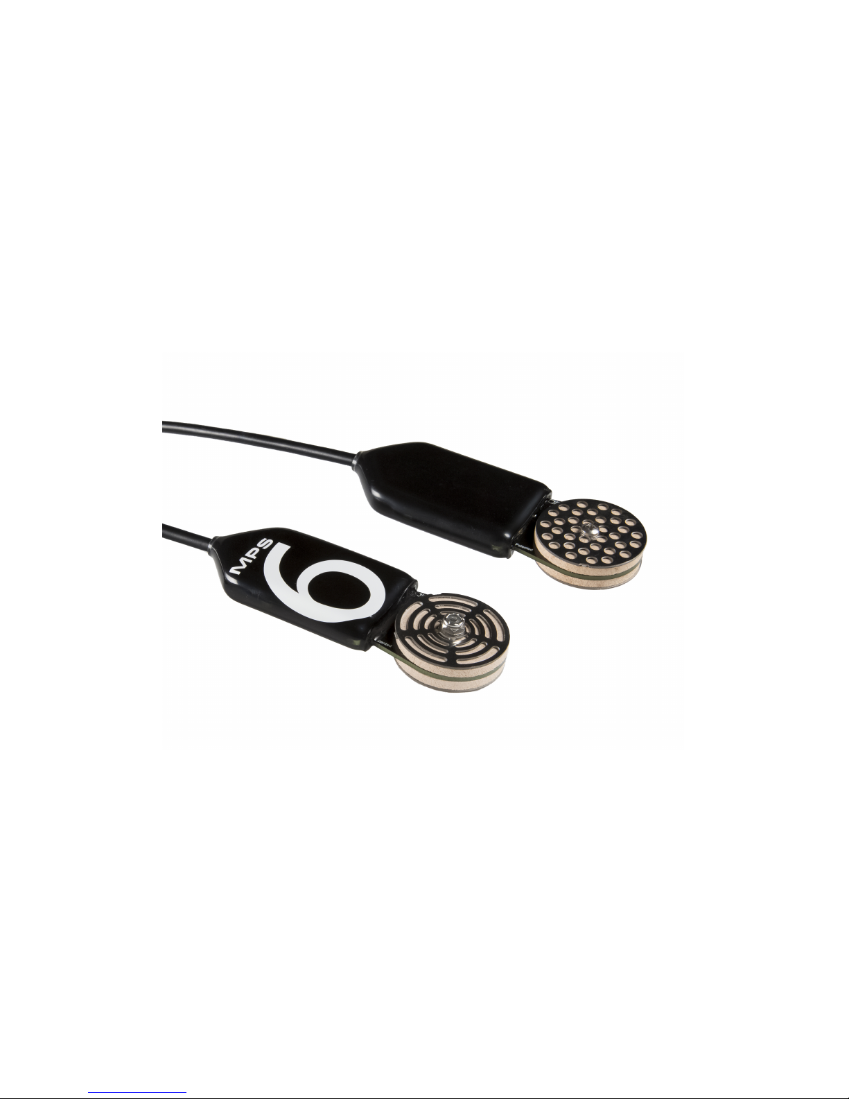
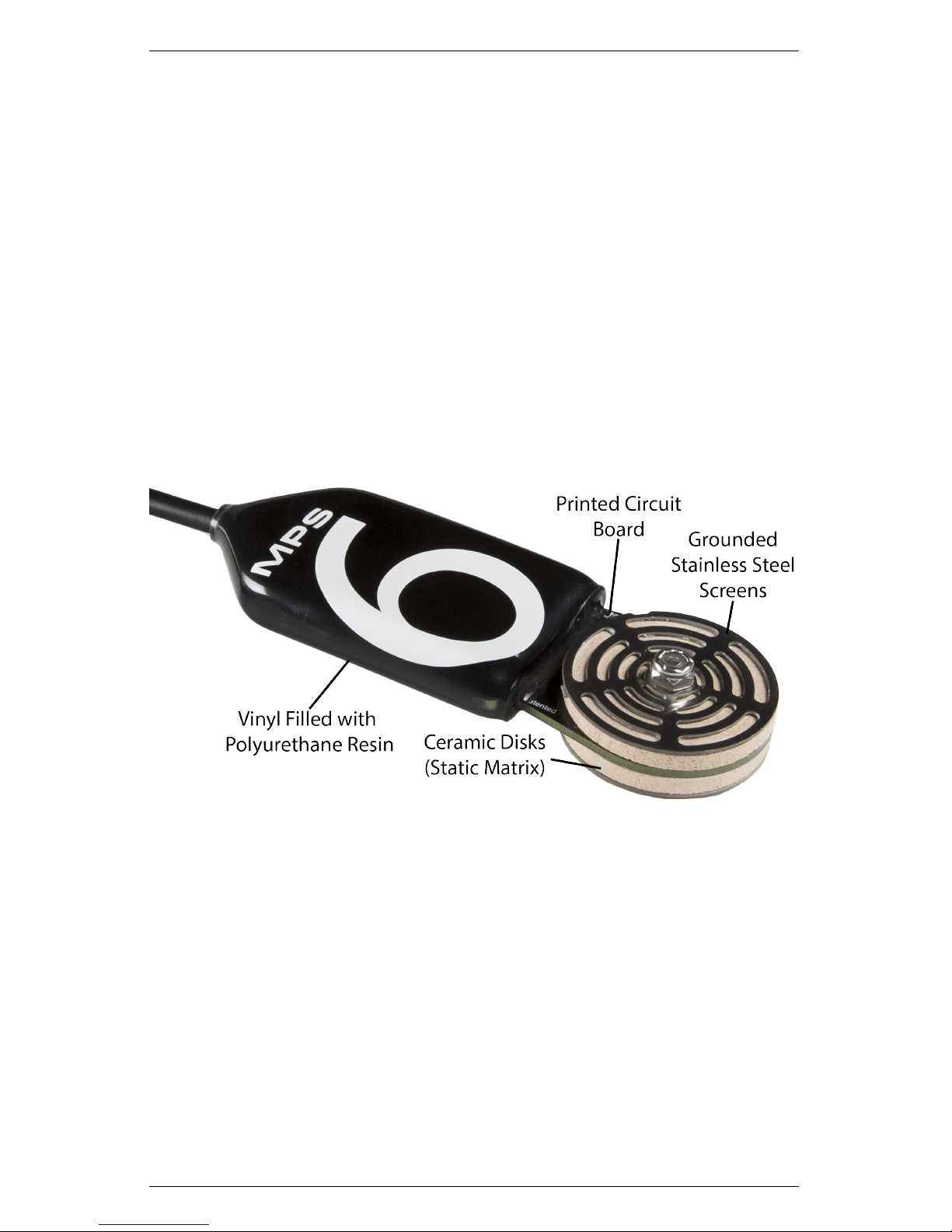
Figure 1: MPS-2 & MPS-6 Components
5
Page 9

3 THEORY MPS-2 & MPS-6
3 Theory
3.1 Water Potential Measurement
There are two basic parameters that describe the state of water in
soil: one is soil water content, or the amount of water per unit of soil,
and the other is soil water potential, or the energy state of water in
the soil. Although water content is useful when trying to describe
the water balance of a soil, i.e. how much water is moving in, out,
or being stored, water potential is often preferred over water content
because it determines how water moves in a soil or from the soil to
the plant. In addition, you can use water potential to determine
plant availability of water, schedule irrigation, or determine the mechanical stress state of soil.
All soil water potential measurement techniques measure the potential energy of water in equilibrium with water in the soil. The Second
Law of Thermodynamics states that connected systems with differing
energy levels move toward an equilibrium energy level. When an object comes into hydraulic contact with the soil, the water potential of
the object comes into equilibrium with the soil water potential. For
example, tensiometers make use of this principal to measure the potential energy of a liquid water reservoir in equilibrium with the soil
water (liquid equilibration), and psychrometers/dew point hygrometers measure the potential energy of water vapor in equilibrium using
soil water (vapor equilibration).
Another category of water potential sensors use a solid matrix equilibration technique to measure the water potential of the soil. This
technique introduces a known material with a static matrix of pores
into the soil and allows it to come into hydraulic equilibrium according to the Second Law of Thermodynamics. Because the two
are in equilibrium, measuring the water potential of the solid matrix
gives the water potential of the soil. Historically, instruments have
measured the thermal conductivity or electrical conductivity of the
solid matrix to determine its water potential with varying degrees of
success.
6
Page 10

MPS-2 & MPS-6 3 THEORY
The MPS-2 and MPS-6 use the same principle, but instead measure the dielectric permittivity of a solid matrix – porous ceramic
discs – to determine its water potential. The dielectric permittivity
of air, the solid ceramic, and water are 1, 5, and 80 respectively. So,
the dielectric permittivity of the porous ceramic discs depends on the
amount of water present in the ceramic disc pore spaces. Measuring
the dielectric permittivity of the ceramic discs allows you to resolve
a wide range of water content measurements .
Water content and water potential are related by a relationship
unique to a given material, called the moisture characteristic curve.
The ceramic used with the MPS-2 and MPS-6 has a wide pore size
distribution and is consistent between discs, giving each disc the
same moisture characteristic curve. Thus, you infer the water potential with the moisture characteristic curve after measuring the water
content of the ceramic.
Equation 1 represents the component variables for determining total
soil water potential (Ψt):
Ψt= Ψp+ Ψg+ Ψo+ Ψ
m
(1)
The subscripts p, g, o, and m are pressure, gravitational, osmotic,
and matric respectively. Of these four components, only Ψoand Ψ
m
are significant and often measured in soil. Ψoarises from dissolved
salts in the soil, and only becomes important if a semi permeable
barrier is present that prevents ionic movement (e.g. plant roots,
cell membranes). Ψmarises from the attraction of water to the soil
particles and is the most important component of water potential
in all but the most salt affected soils. The MPS-2 and MPS-6 both
measure the matric potential of the soil (Ψm). In highly salt affected
soils, it may be necessary to quantify Ψoindependently if you take
measurements of soil water potential relating to biological activity.
3.2 Temperature Measurement
The MPS-2 and MPS-6 use a surface-mounted thermistor to take
temperature readings. The thermistor is located underneath the sensor overmold. The MPS-2 and MPS-6 output temperature readings
7
Page 11

3 THEORY MPS-2 & MPS-6
in◦C unless otherwise stated in your preferences file in either the
DataTrac 3 or ECH2O Utility programs. If the black plastic overmold of the sensor is in direct sunshine, the temperature measurement may read high. Exposure of the overmold to solar radiation
also drastically decreases the life expectancy of the sensor. We do
not recommend installing the sensor with the overmold in the sun.
8
Page 12

MPS-2 & MPS-6 4 RANGE AND ACCURACY
4 Range and Accuracy
4.1 Measurement Range
The MPS-2 and MPS-6 measure the water content of porous ceramic
discs and convert the measured water content to water potential using the moisture characteristic curve of the ceramic.(See Section 3) It
is important for sensor function that the ceramic drains over a wide
water potential range.(See Figure 2) The size of the pore determines
the water potential at which a pore drains (the air entry potential or
bubble pressure), so the ideal ceramic would have pores that range
from very small to relatively large. Decagon specially designed the
ceramic discs to approach this ideal, but they have a total pore volume that is weighted toward the larger pores, which drain at water
potentials within the plant-available range. However, the MPS-2 and
MPS-6 measurement range extends all the way to air-dry (−100,000
kPa).
As the sensor dries past the plant-available range, the total pore volume that drains at a given water potential decreases. At these low
water potentials, the measured water potential can become somewhat
noisy because small changes in measured water content of the ceramic
translate into large changes in water potential. This phenomenon is
most pronounced when the sensor is air-dry. It is expected that the
measured water potential of an uninstalled, air-dry sensor can jump
around throughout the range of −50,000 kPa to −100,000 kPa. The
noise level is much lower when the sensor is installed in the soil, even
at air-dry water potential.
9
Page 13

4 RANGE AND ACCURACY MPS-2 & MPS-6
Figure 2: Moisture characteristic curve derived from mercury
porosimeter data for MPS-2 and MPS-6 ceramic
The air entry potential of the largest pores in the ceramic is about −9
kPa. However, the ceramic dis must have access to air for the large
pores to begin draining and the response of the sensor to change. If
the soil around the sensor has an air entry potential less (drier) than
−9 kPa, air will not reach the sensor until reaching the air entry
potential of the soil. So, in this scenario, the air entry potential
of the soil limits the wet end range, rather than the ceramic discs
themselves. This is generally only an issue when using the sensor in
poorly structured soils with high clay content.
4.2 Measurement Accuracy
Wet end
The MPS-2 and MPS-6 sensors are identical in construction, with
the only difference between the two sensor types being the calibration method applied. We calibrate the MPS-2 and MPS-6 at a vacuum saturated state (0 kPa), and at an air-dry state (−100,000 kPa).
These calibration techniques result in accuracy of ±(25% of reading
+ 2 kPa) over the range of −9 to −100 kPa. The MPS-6 has an
additional four calibration points between 0 and −100 kPa, resulting
10
Page 14

MPS-2 & MPS-6 4 RANGE AND ACCURACY
in accuracy of ±(10% of reading + 2 kPa) over the range of −9 to
−100 kPa.
Dry end
At water potentials drier than −100 kPa, both the MPS-2 and MPS-6
rely on the linear relationship between water content and the logarithm of water potential that is a fundamental characteristic of soils
and the MPS-2 or MPS-6 ceramic disc. Laboratory evaluations have
shown good accuracy and low sensor-to-sensor variability to at least
−1500 kPa (plant permanent wilting point). Field evaluations have
shown low sensor-to-sensor variability to −4500 kPa.(See Figures 3
and 4) Good accuracy should theoretically be achievable to this level,
and well beyond, but evaluation against accurate, independent water
potential measurements low water potential levels is problematic.
Figure 3: Time series MPS water potential data collected at 80 cm
depth under a Beech forest in Switzerland. Note the excellent sensor
agreement down to permanent wilting point (-1,500 KPa).
3
11
Page 15

4 RANGE AND ACCURACY MPS-2 & MPS-6
Figure 4: Time series MPS water potential data collected at 20 cm
under a dry oak forest in Switzerland. Note the range extends well
beyond permenant wilting point.
3
4.3 Calibration
Wet End
We calibrate each MPS-2 and MPS-6 sensor at an air-dry and vacuum saturated state at Decagon Devices. This two-point calibration
results in the accuracy stated above. Although better wet-end accuracy can be achieved through user calibration of the MPS-2 sensor, it
is more cost-effective and convenient to simply order MPS-6 sensors
that are fully calibrated in the wet end at Decagon.
3
Figures 3 and 4 reproduced with permission from Walthert, L. (2013): Soil
as a site factor in Swisss forests(project title). Swiss Federal Institute for Forest,
Snow, and Landscape Research WSL
12
Page 16

MPS-2 & MPS-6 4 RANGE AND ACCURACY
Dry End
As described in the section above, both the MPS-2 and MPS-6 rely
the linear relationship between water content and the logarithm of
water potential for calibration in the dry end. Lab testing and field
evaluations have shown that additional calibrations in this region are
not necessary, but could improve accuracy some.
Decagon strongly discourages dry end calibrations in the pressure
plate apparatus. Our early attempts to improve MPS-1 and MPS-2
sensor dry-end performance in the pressure plate apparatus actually
decreased accuracy, likely because of pressure plate dry end equilibrium issues pointed out in the literature.
4
4.4 Soil Type Dependence
The MPS-2 and MPS-6 calibration is not affected by soil type because
the sensors only measure the water potential of the ceramic discs in
equilibrium with the soil. The MPS-2 and MPS-6 work in any soil
type or other porous media as long as you install them correctly
with adequate hydraulic contact (to ensure timely water potential
equilibrium between the sensor and the medium of interest).
4.5 Hysteresis
The amount of water that a soil holds at a given water potential is
greater if the material is dried to that water potential than if the material is wet up to that water potential; a phenomenon known as hysteresis. Because the MPS-2 and MPS-6 essentially make a dielectric
measurement of water content and convert that to water potential,
sensor measurements have some hysteresis. In most situations, soil
undergoes brief periods of wet up (precipitation or irrigation events)
followed by longer dry down periods where water potential measurements are most useful. We perform MPS-2 and MPS-6 calibration
on the drying leg of the hysteresis loop, so the measurements are
4
e.g. Campbell (1998), Gee et al. (2002), Bittelli and Flury (2009), and
Frydman and Baker (2009)
13
Page 17

4 RANGE AND ACCURACY MPS-2 & MPS-6
most accurate as the soil dries. Measurements as the soil wets up
are slightly drier (more negative water potential) than the true water
potential of the soil. Our wetting and drying tests show the magnitude of the hysteresis error is less than 10 kPa in the −20 kPa to
−100 kPa range.
14
Page 18

MPS-2 & MPS-6 5 CONNECTING TO A LOGGER
5 Connecting to a Logger
The MPS-2 and MPS-6 sensors operate with Decagon’s Em50, Em50R,
and Em50G data loggers or the ProCheck handheld reader. The standard sensor (with 3.5 mm stereo connector) quickly connects to and
is easily configured within a Decagon logger or selected in ProCheck.
The MPS-2 and MPS-6 sensors incorporate several features that also
make them excellent for use with third party loggers. Customers have
the option to purchase the sensor with stripped and tinned wires (pigtail) for terminal connections.
Extending Sensor Cables
The MPS-2 and MPS-6 sensors come standard with a five meter
cable. Customers may purchase custom cable lengths for an additional per-meter fee. This option eliminates the need for splicing
the cable. If you do need to extend the cable, please be sure to adequately waterproof the cable splices as inadequately waterproofed
cable splices are a major failure point. Visit our website for detailed
suggestions on waterproofing cable splices.
5.1 Connecting to Em50/Em50R/Em50G logger
The MPS-2 and MPS-6 work best with the Em50 data logger series. Simply plug the 3.5 mm “stereo plug” connector directly into
one of the five sensor ports. Next, configure your logger port for
the MPS-2 or MPS-6 and set the measurement interval, this may
be done using either ECH2O Utility or DataTrac 3 (see respective
manuals). Please check your software and firmware versions to ensure they support the MPS-2 and MPS-6 sensors. To update to
the latest version, please visit Decagon’s software download site:
http://www.decagon.com/support.
The following software/firmware supports the MPS-2 and MPS-6
sensors.
ECH2O Utility version 1.71 or greater
15
Page 19

5 CONNECTING TO A LOGGER MPS-2 & MPS-6
DataTrac 3 version 3.9 or greater
Em50 version 2.13 or greater
ProCheck readers version 1.53 or greater
Use ECH2O Utility or DataTrac 3 to download data from a Decagon
logger to your computer.
Figure 5: 3.5 mm Stereo Plug Wiring
5.2 Connecting to a Non-Decagon Logger
You may purchase the MPS-2 and MPS-6 sensors for use with nonDecagon data loggers. These sensors typically come pre-configured
with stripped and tinned (pigtail) lead wires for use with screw terminals. Refer to your distinct logger manual for details on wiring. See
Section 5.3 for more information on connecting the MPS-2 and MPS6 sensors to non-Decagon loggers or visit http://www.decagon.com/su
pport/mps-2-and-mps-6-integrator-s-guide/ for the complete Integra-
tor’s guide.
Figure 6: Pigtail End Wiring
Connect the wires to the data logger as shown, with the supply wire
(white) connected to the excitation, the digital out wire (red) to a
digital input, the bare ground wire to ground as illustrated below.
16
Page 20

MPS-2 & MPS-6 5 CONNECTING TO A LOGGER
Figure 7: Wire Illustration
Note: The acceptable range of excitation voltages is from 3.6 to 15
VDC. If you wish to read the MPS-2 or the MPS-6 with the Campbell
Scientific Data Loggers, you need to power the sensors off of the 5
V, 12 V, or switched 12 V port.
If your sensor is equipped with the standard 3.5 mm plug, and you
wish to connect it to a non-Decagon data logger, you have two options.
First, you can clip off the plug on the sensor cable, strip and tin
the wires, and wire it directly into the data logger. This has the
advantage of creating a direct connection with no chance of the sensor becoming unplugged; however, you cannot easily use it in the
future with a Decagon readout unit or data logger. The other option is to obtain an adapter cable from Decagon. The 3-wire sensor
adapter cable has a connector for the sensor jack on one end, and
three wires on the other end for connection to a data logger (this
type of wire is often referred to as a “pigtail adapter”). Both the
stripped and tinned adapter cable wires have the same termination
as seen above; the white wire is excitation, red is output, and the
bare wire is ground.
17
Page 21

5 CONNECTING TO A LOGGER MPS-2 & MPS-6
5.3 Using Non-Decagon Loggers
The MPS-2 and MPS-6 sensors communicate using two different
methods, Serial (TTL) and SDI-12. This chapter discusses the specifics
of each of these communication methods. Please see the complete
Integrator’s guide for more detailed explanations and instructions.
5.4 Communication
Serial Communication
When you apply excitation voltage, the sensor makes a measurement. Within about 40 ms of excitation, two measurement values
transmit to the data logger as a serial stream of ASCII characters.
The serial out is 1200 baud asynchronous with 8 data bits, no parity,
and one stop bit. The voltage levels are 0 to 3.6 V and the logic levels
are TTL (active low). The power must be removed and reapplied to
transmit a new set of values.
The ASCII stream contains two numbers separated by spaces. The
stream terminates with the carriage return character. The first number output is water potential in kilopascals. The second number is
the temperature in degrees Celsius.
SDI-12 Communication
The sensor can also communicate using the SDI-12 protocol, a threewire interface where all sensors are powered (white wire), grounded
(bare wire), and communicate (red wire) on shared wires (for more
info, go to http://www.sdi-12.org). Below is a brief description of
SDI-12 for communication. If you plan on using SDI-12 for communication with the sensor, please see our Integrator’s guide under the support tab on the MPS-2 and MPS-6 product pages at
http://www.decagon.com.
There are several benefits and drawbacks regarding the SDI-12 protocol. One benefit is that you can connect up to 62 sensors to the
18
Page 22

MPS-2 & MPS-6 5 CONNECTING TO A LOGGER
same 12 V supply and communication port on the data logger. This
simplifies wiring because no multiplexer is necessary. The drawback
to using multiple sensors on one bus is that a problem with a single
sensor can bring down the entire array (through a short circuit, etc.).
To avoid this problem, we recommend the user make an independent
junction box with wire harnesses where all sensor wires are wired to
wire lugs so sensors can be disconnected if a problem arises. A single three-wire bundle can be run from the junction box to the data
logger.
Address
The SDI-12 protocol requires that all sensors have a unique address.
MPS-2 and MPS-6 sensors come from the factory with an SDI-12 address of 0. To add more than one SDI-12 sensor to a bus, the sensor
address must be changed. Address options include 0...9, A...Z, a...z.
The best and easiest way to change an address is to use Decagon’s
ProCheck (if the ProCheck does not have this option, please upgrade your firmware to the latest version). SDI-12 addressing can
be accessed in the “CONFIG” menu by selecting “SDI-12 Address.”
Addresses may then be changed by simply pressing the up or down
arrows until you see the desired address and pushing “Enter.”
Power
Customers can power the sensor with any voltage from 3.6 to 15
VDC, but 12 V is the optimal voltage. When using the sensor as
part of an SDI-12 bus, we recommended you excite the sensors continuously to avoid issues with initial sensor startup interfering with
the SDI-12 communications.
Reading
SDI-12 communication allows communication of many parameters at
once. This allows you to see information such as the sensor model,
SDI-12 version, temp, etc. Reading the sensor in SDI-12 mode requires function calls.
19
Page 23

5 CONNECTING TO A LOGGER MPS-2 & MPS-6
The water potential in kilopascals is the first number output by the
sensor. The second number is temperature in Celsius.
The SDI-12 communication protocol is supported in Campbell Scientific data loggers like the CR10X, CR200, CR1000, CR3000, etc.
Direct SDI-12 communication is supported in the “Terminal Emulator” mode under the “Tools” menu on the “Connect” screen. Detailed information on setting the address using CSI data loggers can
be found on our website at http://www.decagon.com/support.
5.5 Installing the Sensors
Because the MPS-2 and MPS-6 measure water potential, they are
not as sensitive to air gaps or soil disturbance as water content sensors. The MPS-2 and MPS-6 need good hydraulic contact with the
surrounding soil. The preferred method for installing the sensor is to
take some native soil, wet it, and pack it in a ball around the entire
sesnor, making sure that the moist soil is in contact with all surfaces
of the ceramic. The sensor and moist soil are then packed into the
soil at the desired depth.
In sandy soils, the soil may not adhere to the sensor even when wet.
In this case the sensor can be packed into soil at the bottom of a
hole dug to the desired installation depth. Again, take care to pack
the sandy soil around the sensor with good contact to all ceramic
surfaces.
After installing the sensor and moist soil, the hole that was excavated to bury the sensor at depth should be back-filled with care
taken to pack the soil back to its native bulk density. Leave at least
six inches of sensor cable beneath the soil before bringing the cable
to the surface. The cable should never be bent in a tight radius as it
leaves the sensor body. At least four inches of cable should exit the
sensor body in a straight line before bending the cable.
20
Page 24

MPS-2 & MPS-6 5 CONNECTING TO A LOGGER
5.6 Campbell Scientific Programs
Because the sensors use digital rather than analog communication,
they require special considerations when connecting to a Campbell
Scientific data logger. Please visit our website at http://www.decagon
.com/support to view sample Campbell Scientific programs.
21
Page 25

6 MAINTENANCE AND TROUBLE MPS-2 & MPS-6
6 Maintenance and Troubleshooting
The MPS-2 and MPS-6 sensors measure the water potential of two
engineered ceramic discs sandwiched between stainless steel screens
and the circuit board. The ceramic discs are somewhat brittle and
can chip or crack if abused. The metal screens afford the discs some
amount of protection, but sharp trauma on the disc edges or massive
impact (such as dropping the sensor onto a hard surface) can cause
the ceramic to break. One or two small chips on the edge of the disc
does not affect the sensor accuracy significantly. However, a cracked
ceramic disc creates a loss of accuracy.
For the MPS-2 and MPS-6 to accurately measure water potential,
the ceramic discs must readily take up water. If you expose the ceramic discs to oils or other hydrophobic substances, it compromises
the ability of the discs to take up water from the soil. This inability
to take up water leads to slow equilibration times and loss of accuracy. We recommend you minimize exposure of the ceramic material
to skin oils and that you do not handle the discs with greasy hands,
or expose the discs to synthetic oils or other hydrophobic compounds.
6.1 MPS-2 & MPS-6 in Frozen Soils
The MPS-2 and MPS-6 measure the dielectric permittivity of two
ceramic discs to measure their water content and then derive their
water potential. The dielectric permittivity of water in the ceramic
discs is 80 compared to a dielectric permittivity of ∼5 for the ceramic
material, and 1 for air. When water freezes to ice, the dielectric
permittivity drops to 5 at the frequency of the sensor measurement
meaning that the MPS-2 or MPS-6 can no longer accurately measure
the water in the ceramic. The MPS-2 and MPS-6 do not accurately
measure the water potential of soil in frozen soil conditions. However, you can measure the water potential of the soil under frozen soil
conditions by measuring the soil temperature accurately (Koopmans
and Miller, 1966). For each 1◦C decrease in temperature below 0
◦
C, the water potential in the soil decreases by ∼1200 kPa. Spaans
and Baker (1996) showed that this relationship is valid in field soils
for water potentials below about −50 kPa.
22
Page 26

MPS-2 & MPS-6 6 MAINTENANCE AND TROUBLE
Rigorous testing indicates that repeated freeze-thaw cycles do not
affect the ceramic discs. Several sensors were equilibrated in saturated soil, and then subjected to numerous freeze thaw cycles in a
temperature control chamber. The freezing rate of the soil containers was at least an order of magnitude faster than could be achieved
in field soil under natural conditions. At several points during the
test, and at the end of the test, the ceramic discs were evaluated for
damage due to repeated rapid freezing with pore spaces full of water.
None of the ceramic discs showed any signs of physical damage, and
none of the sensors showed any significant change in output due to
the freezing tests.
6.2 Troubleshooting
If you encounter problems with the MPS-2 or MPS-6 sensor, they
most likely manifest themselves in the form of incorrect or erroneous
readings. Review these troubleshooting suggestions before contacting Decagon about the sensor.
Data Logger
1. Check to make sure the connections to the data logger are both
correct and secure.
2. Ensure that your data logger batteries are not dead or weakened.
3. Check the configuration of your data logger in ECH2O Utility
or DataTrac 3 to make sure you have selected MPS-2 or MPS-6.
4. Ensure that you are using the most up to date software and
firmware.
Sensors
1. Ensure that your sensors are installed according to section 5.5
“Installation” of this manual.
2. Check sensor cables for nicks or cuts that could cause a malfunction.
23
Page 27

6 MAINTENANCE AND TROUBLE MPS-2 & MPS-6
3. Check the ceramic disc for damage or contamination.
24
Page 28

MPS-2 & MPS-6 7 REFERENCES
7 References
Bittelli, M. And M. Flury, 2009. Errors in Water Retention Curves
Determined with Pressure Plates. Soil Science Society of America
Journal 73: 1453-1460
Campbell, G. S., 1988. Soil water potential measurement: an overview.
Irrigation Science 9:265-273.
Frydman, S. and R. Baker, 2009. Theoretical Soil-Water Characteristic Curves Based on Adsorption, Cavitation, and a Double Porocity
Model. International Journal of Geomechanics 9(6):250-257.
Gee, G. W., A. L. Ward, Z. F. Zhang, G. S. Campbell and J. Mathison, 2002. The influence of hydraulic nonequilibrium on pressure
plate data. Vadose Zone Journal 1:172-178.
Koopmans, R. W. R., and R. D. Miller, 1966. Soil freezing and
soil water characteristic curves, Soil Sci. Soc. Am. Proc. 30, 1966,
680-685.
Spaans, E. J. A., and J. M. Baker, 1996. The soil freezing characteristic: Its measurement and similarity to the soil moisture characteristic, Soil Sci. Soc. Am. J., 60, 1319, 1996.
25
Page 29

8 DECLARATION OF CONFORMITY MPS-2 & MPS-6
8 Declaration of Conformity
Application of Council Directive: 2004/108/EC and 2011/65/EU
Standards to which conformity is
declared:
EN 61326-1:2013 and
EN 50581:2012
Manufacturer’s Name: Decagon Devices, Inc 2365 NE
Hopkins Ct. Pullman, WA 99163
USA
Type of Equipment: Water Potential and Tempera-
ture Sensors
Model Number: MPS-2 & MPS-6
Year of First Manufacture: 2011
This is to certify that the MPS-2 and MPS-6 dielectric water potential sensors, manufactured by Decagon Devices, Inc., a corporation
based in Pullman, Washington, USA meet or exceeds the standards
for CE compliance as per the the aforementioned Council Directives.
All instruments are built at the factory at Decagon and pertinent
testing documentation is freely available for verification.
26
Page 30

Index
Accuracy, 2, 9
Calibration
Dry End, 13
Wet End, 12
CE Compliance, 26
Ceramic Disc, Handling, 22
Ceramic Discs, 7
Communication
Address, 19
Power, 19
Reading, 19
SDI-12, 18
Serial, 18
Connection
Extending Sensor Cables, 15
Customer Support, 1
Declaration of Conformity, 26
Dielectric Permittivity, 7, 22
Email, ii
email, 1
Energy of Water, 6
Fax, ii, 1
Frozen Soils, 22
Hydraulic Contact, 6, 20
Hysteresis, 13
Liability, 3
Maintenace, 22
Manufacturer, 26
Measurement Accuracy
Dry End, 11
Wet End, 10
Model Number, 26
Moisture Characteristic Curve, 7
Range, 9
References, 25
Sandy Soil, 20
Sensor, Installation, 20
Soil Water Content, 6
Soil Water Potential, 6
Telephone, ii, 1
Temperature, Range, 2
Tensiometers, 6
Thermodynamics, Second Law, 6
Troubleshooting
Data Logger, 23
Sensors, 23
Warranty, 3
Water Potential, Components, 7
Water Potential, Range, 2
Wiring, 16
27
 Loading...