

Page 1
KD2 Pro
Thermal Properties Analyzer
Operator’s Manual
Version 10
Page 2

Decagon Devices, Inc.
2365 NE Hopkins Ct.
Pullman, WA 99163 USA
Tel: 1-509-332-2756
Fax: 1-509-332-5158
Trademarks:
“KD2 Pro” is a registered trademark of
Decagon Devices, Inc.
©2008-2011 Decagon Devices, Inc.
All rights reserved.
Page 3

KD2 Pro Operator’s Manual
Table of Contents
Contents
1. Introduction . . . . . . . . . . . . . . . . . . . . . . . . 1
About the KD2 Pro . . . . . . . . . . . . . . . . . . . . . . . . . 1
Customer Support . . . . . . . . . . . . . . . . . . . . . . . . . . . 1
Warranty Information . . . . . . . . . . . . . . . . . . . . . . . . 2
Seller’s Liability . . . . . . . . . . . . . . . . . . . . . . . . . . . . . 2
Repair Instructions . . . . . . . . . . . . . . . . . . . . . . . . . . 3
Repair Costs. . . . . . . . . . . . . . . . . . . . . . . . . . . . . . . . 3
2. KD2 Pro Overview . . . . . . . . . . . . . . . . . . . 4
Specifications. . . . . . . . . . . . . . . . . . . . . . . . . . . . . . . 4
Keypad Operation . . . . . . . . . . . . . . . . . . . . . . . . . . 6
Choosing a Sensor. . . . . . . . . . . . . . . . . . . . . . . . . . . 7
Installing the Sensors . . . . . . . . . . . . . . . . . . . . . . . 13
Measurements In Concrete. . . . . . . . . . . . . . . . . . . 14
Measurements In Insulation . . . . . . . . . . . . . . . . . . 14
3. The Menus . . . . . . . . . . . . . . . . . . . . . . . . 15
The Main Menu. . . . . . . . . . . . . . . . . . . . . . . . . . . . 15
Taking a Measurement . . . . . . . . . . . . . . . . . . . . . . 16
The Data Menu . . . . . . . . . . . . . . . . . . . . . . . . . . . . 19
The Configuration Menu . . . . . . . . . . . . . . . . . . . . 21
The Auto Mode. . . . . . . . . . . . . . . . . . . . . . . . . . . . 25
4. The KD2 Pro Utility. . . . . . . . . . . . . . . . . 27
System Requirements . . . . . . . . . . . . . . . . . . . . . . . 27
Installation . . . . . . . . . . . . . . . . . . . . . . . . . . . . . . . . 28
How Saved Data Are Organized . . . . . . . . . . . . . . 30
Erasing Your Data. . . . . . . . . . . . . . . . . . . . . . . . . . 32
i
Page 4

KD2 Pro Operator’s Manual
Table of Contents
Setting the Date and Time. . . . . . . . . . . . . . . . . . . .32
Setting the Auto Mode . . . . . . . . . . . . . . . . . . . . . .33
Viewing KD2 Pro Information. . . . . . . . . . . . . . . . 36
The Menus and Their Functions. . . . . . . . . . . . . . .36
Troubleshooting. . . . . . . . . . . . . . . . . . . . . . . . . . . .41
5. Good Practices . . . . . . . . . . . . . . . . . . . . .43
6. Measuring Liquids. . . . . . . . . . . . . . . . . .46
Liquid Sample Temperature Control . . . . . . . . . . . 48
7. Care and Maintenance . . . . . . . . . . . . . . .50
Cleaning & Caring for the Sensors . . . . . . . . . . . . .50
Changing the Batteries. . . . . . . . . . . . . . . . . . . . . . .50
Troubleshooting. . . . . . . . . . . . . . . . . . . . . . . . . . . .51
Verifying Sensor Performance . . . . . . . . . . . . . . . .51
8. KD2 Pro Theory . . . . . . . . . . . . . . . . . . . .54
Further Reading . . . . . . . . . . . . . . . . . . . . . .60
Appendix A . . . . . . . . . . . . . . . . . . . . . . . . . .61
Table of Thermal Units . . . . . . . . . . . . . . . . . . . . . .61
Appendix B . . . . . . . . . . . . . . . . . . . . . . . . . .62
Send Feedback to Decagon. . . . . . . . . . . . . . . . . . .62
KD2 Pro CE Compliance . . . . . . . . . . . . . . .63
Index . . . . . . . . . . . . . . . . . . . . . . . . . . . . . . .64
ii
Page 5

KD2 Pro Operator’s Manual
1. Introduction
1. Introduction
Welcome to your new KD2 Pro Thermal Properties Analyzer.
This guide is designed to help you understand and use your
instrument to the best of its capability.
About the KD2 Pro
The KD2 Pro is a handheld device used to measure thermal
properties. It consists of a handheld controller and sensors that
can be inserted into the medium you wish to measure. The single-needle sensors measure thermal conductivity and resistivity;
while the dual-needle sensor also measures volumetric specific
heat capacity and diffusivity. Further details about the measurements and how they’re made are given in chapters 2 and 3 of
this guide.
Customer Support
If you ever need assistance with your KD2 Pro, or if you just
have questions or feedback, there are several ways to contact
us. Customer service representatives are available to speak
with you Monday thru Friday, between 8am and 5pm Pacific
time.
Phone:
1-800-755-2751 (Toll free to customers in US and Canada)
1-509-332-2756 (for international customers)
Fax:
1-509-332-5158
E-mail:
support@decagon.com or sales@decagon.com
1
Page 6

KD2 Pro Operator’s Manual
1. Introduction
If contacting us by email or fax, please include as part of your
message your instrument’s serial number, your name, address,
phone, and fax number.
NOTE: If you purchased your KD2 Pro through a distributor, please contact them for assistance.
Warranty Information
The KD2 Pro has a 30-day satisfaction guarantee and a oneyear warranty.
Seller’s Liability
Seller warrants new equipment of its own manufacture against
defective workmanship and materials for a period of one year
from date of receipt of equipment (the results of ordinary wear
and tear, neglect, misuse, accident and excessive deterioration
due to corrosion from any cause are not to be considered a
defect); but Seller’s liability for defective parts shall in no event
exceed the furnishing of replacement parts F.O.B. the factory
where originally manufactured. Material and equipment covered hereby which is not manufactured by Seller shall be covered only by the warranty of its manufacturer. Seller shall not be
liable to Buyer for loss, damage or injuries to persons (including
death), or to property or things of whatsoever kind (including,
but not without limitation, loss of anticipated profits), occasioned by or arising out of the installation, operation, use, misuse, non-use, repair, or replacement of said material and
equipment, or out of the use of any method or process for
which the same may be employed. The use of this equipment
constitutes Buyer’s acceptance of the terms set forth in this
warranty. There are no understandings, representations, or warranties of any kind, express, implied, statutory or otherwise
(including, but without limitation, the implied warranties of
2
Page 7

KD2 Pro Operator’s Manual
1. Introduction
merchantability and fitness for a particular purpose), not
expressly set forth herein.
Repair Instructions
If your KD2 Pro should ever require a repair, call Decagon at
(509) 332-2756 or 1-800-755-2751 (United States and Canada). We will ask you for your address, phone number, your
KD2 Pro’s serial number, and your current firmware version.
For non-warranty repairs, we will also ask for a method of
payment.
Before shipping your instrument to Decagon, please
contact Decagon to obtain a Request Maintenance
Authorization Number (RMA). This will allow Decagon’s
repair staff to keep track of your KD2 Pro. Once you have
acquired an RMA, send your KD2 Pro to Decagon. Please
include a document listing the complete shipping address,
name, and department of the person responsible for the
instrument, as well as a description of the problem. This will
better help our technicians and shipping department to expedite repair on your KD2 Pro, and ship it back to you.
Please pack your KD2 Pro carefully. Ship it back in the carrying case, preferably inside a cardboard box. Ship to:
Decagon Devices Inc.
2365 NE Hopkins Court
Pullman, WA 99163
Repair Costs
Manufacturer’s defects and instruments under warranty will be
repaired at no cost. For non-warranty repairs, costs for parts,
labor, and shipping will be billed to you.
3
Page 8

KD2 Pro Operator’s Manual
2. KD2 Pro Overview
2. KD2 Pro Overview
The KD2 Pro is a battery-operated, menu-driven device that
measures thermal conductivity and resistivity, volumetric specific heat capacity and thermal diffusivity. The KD2 Pro has
been designed for ease of use and maximum functionality.
Specifications
Operating Environment:
Controller: 0 to 50 °C
Sensors: -50 to +150 °C
Power: 4 AA cells
Battery Life: At least 500 readings in constant use or 3 years
with no use (battery drain in sleep mode < 50 uA)
Case Size: 15.5 cm x 9.5 cm x 3.5 cm
Display: 3 cm x 6 cm, 128 x 64 pixel graphics LCD
Keypad: 6 key, sealed membrane
Data Storage: 4095 measurements in flash memory (both
raw and processed data are stored for download)
Interface: 9-pin serial
Read Modes: Manual and Auto Read
4
Page 9

KD2 Pro Operator’s Manual
2. KD2 Pro Overview
Sensors:
60 mm (small) single-needle (KS-1):
Size: 1.3 mm diameter x 60 mm long
Range: 0.02 to 2.00 W/(m· K) (thermal conductivity)
50 to 5000 °C·cm/W (thermal resistivity)
Accuracy (Conductivity): ± 5% from 0.2 - 2 W/(m· K)
±0.01 W/(m· K) from 0.02 - 0.2 W/(m· K)
Cable length: 0.8 m
100 mm (large) single-needle (TR-1):
Size: 2.4 mm diameter x 100 mm long
Range: 0.10 to 4.00 W/(m· K) (thermal conductivity)
25 to 1000 °C·cm/W (thermal resistivity)
Accuracy (Conductivity): ±10% from 0.2 - 4 W/(m· K)
±0.02 W/(m· K) from 0.1 - 0.2 W/(m· K)
Cable length: 0.8 m
30 mm dual-needle (SH-1):
Size: 1.3 mm diameter x 30 mm long, 6 mm spacing
Range: 0.02 to 2.00 W /(m· K) (thermal conductivity)
50 to 5000 °C·cm/W (thermal resistivity)
0.1 to 1 mm2/s (diffusivity)
3
0.5 to 4 mJ/(m
K) (volumetric specific heat)
Accuracy: (Conductivity) ± 10% from 0.2 - 2 W/(m· K)
±0.01 W/(m· K) from 0.02 - 0.2 W/(m· K)
(Diffusivity) ±10% at conductivities above
0.1 W/(m· K)
(Volumetric Specific Heat) ±10% at conductivi-
ties above 0.1 W/(m· K)
Cable length: 0.8 m
5
Page 10
KD2 Pro Operator’s Manual
2. KD2 Pro Overview
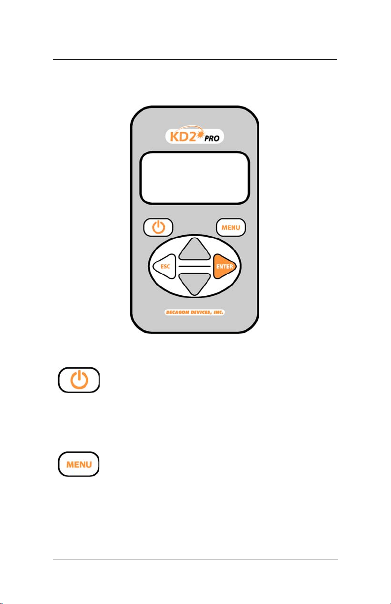
Keypad Operation
POWER: Located to the left below the screen,
this key activates and deactivates the KD2 Pro.
(Note: The device will automatically turn off if
not used for more than 10 minutes, except while running in
Auto Mode.)
MENU: Located to the right below the screen,
this key cycles between the menus at the top of
the screen.
6
Page 11
KD2 Pro Operator’s Manual
2. KD2 Pro Overview
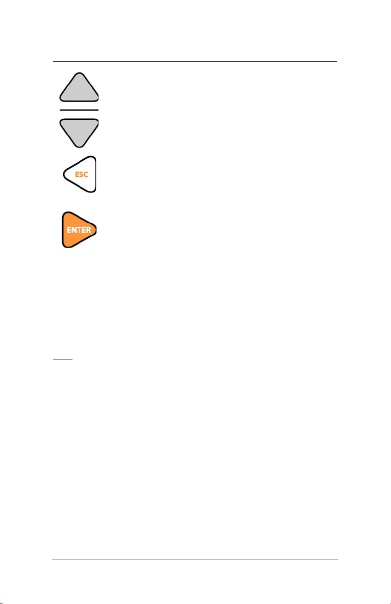
ARROW KEYS: Located in the center of the
keypad, these keys navigate within menus and
sub-menus, and modify different settings in sub-
menus. Holding down an arrow key allows you to
scroll between different options quickly.
ESCAPE: This key backs out of sub-menus and
can be used to cancel certain actions (see “Erase,”
in “Data Menu,” Chapter 2).
ENTER: This key is used to make selections
within menus and sub-menus, and also begins
taking measurements (see “Making a Measure-
ment,” “Main Menu,” below).
Choosing a Sensor
The KD2 Pro comes with three separate sensors, each of
which is designed for measurements in specific sample types.
KS-1
The small (60 mm long, 1.3 mm diameter) single needle KS-1
sensor measures thermal conductivity and thermal resistivity. It
is designed primarily for liquid samples and insulating materials
(thermal conductivity < 0.1 W (W/m· K)). The KS-1 sensor
applies a very small amount of heat to the needle which helps to
prevent free convection in liquid samples (see Chapter 6 in this
manual regarding measurement in liquid samples for more information). However, the small size of the needle and typically
short heating time make the KS-1 a poor choice for granular
samples such as soil and powders where contact resistance can
be an important source of error. In insulating materials, the
7
Page 12

KD2 Pro Operator’s Manual
2. KD2 Pro Overview
errors from contact resistance become negligible making the KS1 sensor a good choice.
TR-1
The large (100 mm long, 2.4 mm diameter) single needle TR-1
sensor measures thermal conductivity and thermal resistivity.
It is designed primarily for soil, concrete, rock, and other granular or solid materials. The relatively large diameter and typically longer heating time of the TR-1 sensor minimize errors
from contact resistance in granular samples or solid samples
with pilot holes. The TR-1 needle heats the sample significantly more than the KS-1 sensor, which allows it to measure
higher thermal conductivity samples (see specifications), but
means that you
TR-1 sensor
should not measure liquid samples with the
. The large diameter of the TR-1 is more robust
than the KS-1, meaning that it is less likely to be damaged by
normal usage conditions in soil or other solid materials. Additionally, the dimensions of the TR-1 sensor conform to the
specifications for the Lab Probe called out by the IEEE 442-03
Guide for Soil Thermal Resistivity Measurements.
SH-1
The dual needle SH-1 sensor measures volumetric heat capacity, thermal diffusivity, thermal conductivity, and thermal resistivity. The SH-1 is compatible with most solid and granular
materials, but should not be used in liquids due to the
large heat pulse and possible resulting free convection in liquid samples.
Read Time
The read time is the time, in minutes, during which data are
taken to compute thermal properties. Heat is applied for half
of the time, and measurements are taken over the full time.
8
Page 13

KD2 Pro Operator’s Manual
2. KD2 Pro Overview
Thirty seconds are allowed for temperature equilibration
before heating starts, so the entire time for a measurement is
the time set here plus 30 seconds. Sixty temperature readings
are taken during the read time, so the number entered here is
also the number of seconds between temperature readings.
This number is displayed in the upper right corner of the
screen, and is available with each data record after downloading. Default read times are 1 minute for the KS-1 sensor, 2
minutes for the SH-1 sensor and 5 minutes for the TR-1 sensor.
The longer read time for the TR-1 sensor helps to prevent
errors caused by effects of the large diameter needle and contact resistance between the sensor and the sample in granular
and solid materials. If you wish to measure thermal properties
of a sample with large grains or of a solid sample with a pilot
hole that is significantly larger in diameter than the sensor, it is
best to use the TR-1 needle and configure the read time to the
maximum allowed 10 minutes.
The shorter read time for the KS-1 sensor reduces the amount
of heat input into the sample. This is especially important
with liquid samples where excessive sample heating can cause
errors from free convection (see section on measuring liquid
samples for more details). In low viscosity samples (e.g. water
and aqueous solutions), the KS-1 read time should be configured to the minimum allowed 1 minute.
To set the read time, go to the Read Time menu selection and
press Enter. Arrow down to the probe for which you want to
set the read time and press Enter, Arrow up or down to the
read time you want and press Enter.
9
Page 14
KD2 Pro Operator’s Manual
2. KD2 Pro Overview
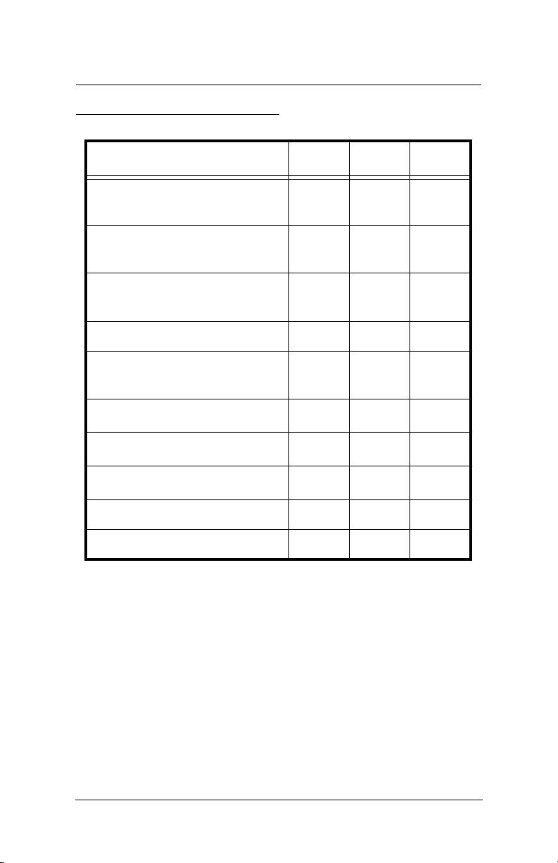
KD2 Pro Sensor Compatibility
Sample Material KS-1 TR-1 SH-1
Low viscosityliquids
Best
1
No No
(e.g. water)
High viscosity liquids
Best
2
Ok
2
No
(e.g. glycerol, oil)
3
Insulation and insulating
Best
Ok Ok
materials
Moist soil No Best Ok
4
Dry soil, powders, granu-
No
Best
Ok
lar materials
Concrete No
Rock No
Other solids No
Best
Best
Best
5
5
5
Ok
Ok
Ok
6
6
Volumetric specific heat No No Best
Thermal diffusivity No No Best
1
In low viscosity liquids, the read time should be set to the
minimum allowed 1 minute and should only be used in low
power mode to avoid free convection.
2
In high viscosity liquids, the KS-1 or TR-1 sensor should
only be used in low power mode.
3
The KS-1 or TR-1 needles in low power mode with 10 min
read time give good results with insulation. Heater temperatures with high power mode are quite high for insulation measurements.
10
Page 15

KD2 Pro Operator’s Manual
2. KD2 Pro Overview
4
In dry granular materials where contact resistance can be significant, extending the read time to the maximum allowed 10
minutes will produce the most accurate results.
5
In solid materials where a pilot hole has been drilled and
contact resistance can be significant, using thermal grease and
extending the read time to the maximum allowed 10 minutes
will produce the most accurate results.
6
The SH-1 sensor will take accurate measurements in rock
and cured concrete, but it is very difficult to drill small diameter, parallel holes in these materials to accommodate the SH-1
needles.
Power Mode
With the KD2 Pro, you have the ability to configure the
device to measure each of the three sensor types in either high
power mode or low power mode. In high power mode, the
KD2 Pro applies a relatively large heating current to the sensor during a measurement resulting in greater sensor heating.
In low power mode, the KD2 Pro applies a small current to
the sensor resulting in less heating of the sensor. The KS-1
sensor defaults to low power mode, while the TR-1 and SH-1
needles both default to high power mode. We recommend
that the power mode only be changed from the default settings for special measurements by expert users. In all but a
few cases, changing the power mode from the default settings
will result in poorer accuracy than can be expected in the
default power mode. Do not change the power mode from
the default settings unless you are an expert user and are making a specialized measurement. Feel free to contact Decagon
to discuss specifics of your measurement before changing
from the default power mode setting. More specific comments regarding power mode adjustment include:
11
Page 16

KD2 Pro Operator’s Manual
2. KD2 Pro Overview
• Do NOT attempt to make measurements in liquids with
the KS-1 or TR-1 in high power mode. The additional
heating from the higher heat input will cause free convection and compromise the measurement (see Chapter
6 for more information on free convection).
• Do not attempt to make measurements in low viscosity
fluids with the SH-1 (dual needle) sensor in either high
power or low power mode.
• One motivation behind allowing power mode configuration is to allow the TR-1 and SH-1 sensors to make better measurements in frozen materials where the
decreased heat input in low power mode is less likely to
cause phase change (melting) of the frozen sample.
One situation where we do recommend a non-default
power mode setting is the measurement of thermal conductivity of snow. In this case, we recommend using the
TR-1 needle to reduce issues with contact resistance,
and we recommend configuring the sensor to low
power mode to reduce issues with melting.
Installing the Sensors
The KD2 Pro’s three sensors have been designed for ease of
installation and use. The following considerations should be
observed when installing the sensors.
• The sensor should be inserted all the way into the
medium to be measured.
• For the single-needle 10cm sensor, a drill bit has been
included that can be used to drill a pilot hole in material
such as wood or hard soil. For rock (or cured concrete),
a 1/8” hole can be drilled with a rotohammer and filled
12
Page 17

KD2 Pro Operator’s Manual
2. KD2 Pro Overview
with thermal grease to provide optimal contact between
the needle and the rock.
• For the dual-needle sensor, the needles must remain
parallel to each other during insertion to make an
accurate reading. Therefore, take care in tough material,
which can splay the prongs and adversely affect readings. Use the provided red tab with pilot holes to make
sure that the needles have the correct spacing.
• Because the sensors give off a heat pulse, you must
allow a minimum of 1.5 cm of material parallel to the
sensor in all directions, or errors will occur.
• DO NOT BEND THE NEEDLES, as this can damage the sensor beyond repair. If the needle becomes
bent, do not bend it back; contact Decagon for a
replacement.
• Good thermal contact between the sensors and the
medium being measured is critical for accurate measurements if a hole is drilled for sensor insertion. Make
sure that the sensor fits tightly into the hole. Use the
thermal grease included with your KD2 Pro to improve
contact in larger holes or grainy samples.
Measurements In Concrete
If the KD2 Pro is to be used for measurements in concrete, it
is preferrable to mold pilot holes in wet concrete using the
pilot pins furnished with your KD2 Pro using the following
procedure.
• Coat pilot pin with vaseline.
• Install pin at least 100mm deep while concrete is wet.
• Remove pin when concrete has dried.
• Coat the single 10cm sensor with thermal grease, insert
sensor into the cast hole and begin to take readings.
13
Page 18

KD2 Pro Operator’s Manual
2. KD2 Pro Overview
If measurements need to be made in concrete that has already
been cured, holes can be drilled into the sample using the procedure outlined above in the section titled “Installing the Sensors.”
Measurements In Insulation
Insulation measurements are best made with the KS-1 probe
using a 10 minute read time. The long read time minimizes
contact resistance errors, and the low heat of the KS-1 needle
reduces free convection errors. In foam insulation a hole
should be drilled for the probe. Simply pushing in the needle
can cause the insulation to bunch in front of the needle tip
resulting in a poor fit and a consequently a faulty reading. In
fiber type insulation materials, assure that the insulating materials are not unduly disturbed by the needle insertion. (i.e.
pushed in front of the needle tip). Do not allow the probe to
move during the measurement.
14
Page 19
KD2 Pro Operator’s Manual
1
2
4
5
7
6
8
3
3. The Menus
3. The Menus
The KD2 Pro features four main menus: MAIN, DATA,
CONFIG, and AUTO (respectively). These menus access the
KD2 Pro’s features, and have been designed for ease of use.
Here is a more detailed description of each menu.
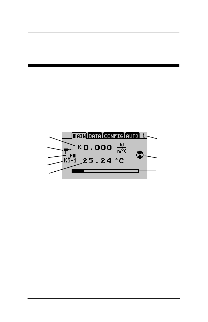
The Main Menu
The Main Menu is responsible for taking measurements from
whatever medium a sensor is inserted into.
What you see:
1. The thermal property reading and the currently selected
unit. The type of reading is indicated by the letter to the
left of the reading:
K = thermal conductivity
C = specific heat capacity
D = thermal diffusivity
rho = thermal resistivity
NOTE: When the spinner icon is visible, press the arrow keys to
scroll through and change the current unit and measurement type.
15
Page 20

KD2 Pro Operator’s Manual
3. The Menus
2. Icon showing connected sensor type.
3. Indicator for high power mode (HPM) or low power
mode (LPM).
4. The currently connected sensor type and sensor name.
5. The measurement temperature in °C or °F.
6. Indicates the length of the reading in minutes
7. Indicates the status of a reading.
8. Progress bar that displays elapsed time.
The purpose of the Main Menu is to take measurements. The
next section will explain how to do this.
Taking a Measurement
It is easy to take measurements with the KD2 Pro. Do the following to make a measurement:
NOTE: If the temperature of the sample is different from
the temperature of the needle, the needle must equilibrate
to the surrounding temperature before beginning a reading.
1. Attach appropriate sensor then turn on the KD2 Pro.
2. Properly insert the sensor into the material to be measured. (See “Installing the sensors” in this chapter for
instructions.)
16
Page 21
KD2 Pro Operator’s Manual
3. The Menus
3. When the KD2 Pro turns on, you should be in the Main
Menu. If not, press the Menu key until you arrive there.
Press Enter to begin the measurement.
4. An icon will appear on the left and right side of the screen.
The icon at left indicates the type of sensor connected.
The circular icon indicates that a reading is underway. It
will change to a thermometer icon to indicate whether the
measurement is currently in heating or cooling mode;
when the thermometer is rising, heat is applied to the needle, and when it is falling, heat is off. A progress bar shows
the elapsed time.
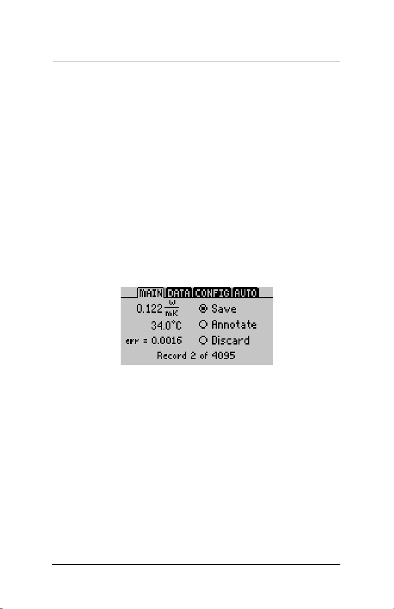
5. When the progress bar has fully darkened, the results are
displayed as follows:
On the left side of the screen are three measured
values:
• Thermal Properties Reading - The calculated thermal
measurement.
• Starting Temperature - The initial tempera- ture prior
to any heating or cooling.
•
Err Value-
The err value is the relative goodness of fit or
relative error for the data set. It is a measure of how well
the model fits the data (the Theory chapter of this manual describes the model that is fit to the data). If the
model fits the data perfectly, then err = 0.0000. The pur-
17
Page 22

KD2 Pro Operator’s Manual
3. The Menus
pose of displaying this reading is to indicate possible
problems with the data. A good data set will give err values below 0.0100, except at very low thermal conductivity (e.g. insulation materials). If the err value is unusually
large, discard the data, wait fifteen minutes and take
another reading.
On the right side of the screen are three save options:
• Save - You can save your reading as is;
• Annotate - You can attach a sample ID to your reading;
• Discard - Cancel the current reading and return to the
main screen.
NOTE: If the data memory is full or the sample temperature was unstable during a reading, an error message is
displayed at the bottom of the screen. If this should happen, you may still take readings but you will be unable to
save them to the KD2 Pro.
How to annotate a reading: When you select the “Anno-
tate” option, you will see a series of lines with an arrow above
and below the first position. Use the up and down arrow keys
to select a letter or number and press Enter to move to the
next character (as shown below). If you have annotated a previous reading, the old annotation will remain to be modified
or deleted.
18
Page 23

KD2 Pro Operator’s Manual
3. The Menus
Repeat this until you reach the last character. When finished,
simply continue to press Enter until you reach the end of the
row. Holding Enter or Escape will allow you to scroll left and
right through the Sample ID quickly.
NOTE: It is important to wait for about fifteen minutes
between readings, if the sensor is left in the same location! If multiple measurements of a sample are made too rap-
idly in succession, the sample’s temperature will not have had
enough time to equilibrate from the previous reading, and the
resulting measurement will be inaccurate. For best results, the
sample should be as close to equilibrium as possible. A good
environment for equilibration can be provided by placing the
KD2 Pro sensor and sample in an isothermal chamber or styrofoam box.
The Data Menu
The Data Menu allows you to view stored data, download data
to a computer, and erase the data from your KD2 Pro. It also
displays how many readings have been recorded out of the
total 4,095 that can be stored.
Here is description of each sub-menu:
VIEW: This menu allows you to view all data currently stored
on your KD2 Pro. Press Enter to access the readings, and use
19
Page 24

KD2 Pro Operator’s Manual
3. The Menus
the arrow keys to scroll through them. By pressing Enter a
second time, you can see more detail about a reading.
DOWNLOAD: This menu sends the data saved in the KD2
Pro to your computer. You have two download options:
• Download All - This downloads the temperature read-
ings as well as the measured thermal properties.
• Download Summary - This downloads just the mea-
sured thermal properties.
NOTE: Your KD2 Pro comes with KD2 Pro Utility software
for use with Microsoft Windows. The Utility makes downloading data to your computer very easy. In general, you
should use the KD2 Pro Utility to download data instead of
the download option on the KD2 Pro.
If you are unable to use the KD2 Pro Utility, you can use terminal software to transfer the data from your KD2 Pro to
your computer. The following steps should apply to most terminal software programs:
1. Configure your terminal software with the following settings:
• 9600 baud
• 8 data bits, 1 stop bit, no parity
• No software/hardware flow control
• Append line feeds to incoming line ends
• Echo typed characters locally.
2. Connect your KD2 Pro to an available serial port on your
computer using the included RS-232 serial cable.
3. Set your terminal software to capture received data if you
want to save the data.
20
Page 25

KD2 Pro Operator’s Manual
3. The Menus
4. Select the appropriate option from the Download menu in
the KD2 Pro.
ERASE: This will erase all stored data on your KD2 Pro.
WARNING! This feature will completely erase all data
on your KD2 Pro, and once activated, it cannot be
undone!
To erase data:
1. Press Enter to select the Erase sub-menu. The screen
“Erase all stored data?” will appear.
2. Press Enter again to erase the memory or Escape if you
decide not to continue. “Erasing...” will be displayed as
data is being removed, which usually takes about 6 seconds.
3. When this is complete, you will be returned to the Data
Menu.
The Configuration Menu
The Configuration Menu allows you to change system settings
such as the date, time, measurement units, and also view information about your KD2 Pro. A battery icon will also display
the remaining percentage of battery power. A description of
each sub-menu follows.
21
Page 26

KD2 Pro Operator’s Manual
3. The Menus
DATE: To change the current date,
1. Press Enter to select the date display.
2. The current date will appear in the center of the screen, in
day/month/year format. A pair of arrows will be present
above and below the first number.
3. Use the up & down arrow keys to change this number.
4. Press Enter to move to the next number, and repeat step
#3. If you need to return to the previous number, press
Escape.
5. When you have finished changing the last number, press
Enter and you will be returned to the Configuration
Menu.
TIME: To change the current time,
1. Press Enter to select the Time display.
2. The current time will appear in the center of the screen, in
24-hour format. A pair of arrows will be present above
and below the first number.
3. Use the up & down arrow keys to change this number.
22
Page 27

KD2 Pro Operator’s Manual
SI and English Unit Equivalents
Thermal
Conductivity
(K)
Thermal
Resistivity
()
Volu me tr ic
specific heat
(C)
Thermal
Diffusivity
(D)
SI W
(m· K)
°C · cm
W
MJ
(m
3
· K)
mm
2
s
English BTU
hr· ft °F
hr· ft °F
BTU
BTU
°F· ft
3
ft
2
hr
3. The Menus
4. Press Enter to move to the next number, and repeat step
#3. If you need to return to the previous number, press
Escape.
5. When you have finished changing the last number, press
Enter and you will be returned to the Configuration
Menu.
UNITS: You can choose to represent measurement data in
either SI or English units. Press Enter to select an option.
When you return to the Main Menu, pressing the arrow keys
allows you to scroll through and change the current unit and
measurement type.
NOTE:
(m °C) are the same as readings in watts per meters
Kelvin (W/m· K), as Celsius and Kelvin degrees are on
the same temperature scale.
READ TIME: Allows you to change the read time duration
for each sensor type. To change a read time select the sensor
and press enter. Using the up/down arrows to select the new
read time. Press enter to save the changes or ESC to cancel
Readings in watts per meters-degree Celsius W/
23
Page 28

KD2 Pro Operator’s Manual
3. The Menus
with out saving the changes. For more information refer to
the read time section in chapter 2.
POWER MODE: Allows you to change the power mode to
be used for each sensor type. Do not change the power
mode from the default settings unless you are an expert
user and are making a specialized measurement. To
change the power mode, select the sensor and press enter to
toggle between high and low power mode. Press ESC or
MENU to accept the changes and exit the power mode menu.
For more information on situations where you might want to
change from the default power mode, see the Power Mode
section in Chapter 2.
CONTRAST: Allows you to change the screen contrast level.
Press Enter and follow the on-screen instructions to modify
the contrast.
24
Page 29

KD2 Pro Operator’s Manual
1
7
2
5
8
9
10
6
3
4
3. The Menus
ABOUT: Displays the serial number and firmware version of
your KD2 Pro.
The Auto Mode
The Auto Mode allows you to set up the KD2 Pro to take
readings automatically. You can select a measurement time in
intervals of 15 minutes. The reading will be taken in the currently selected units from the Main Menu, and will begin as
soon as you select this option. NOTE: Should the KD2 Pro’s
data memory ever become full (4,095 readings), you may still
take readings, but you cannot save them until you erase the
stored readings.
25
Page 30

KD2 Pro Operator’s Manual
3. The Menus
What you see:
1. Final measurement displayed in the selected units.
2. Icon showing connected sensor type.
3. Indicator for high power mode (HPM) or low power
mode (LPM).
4. Currently connected sensor type.
5. Measurement temperature in °C or ºF.
6. Indicates the length of the reading in minutes
7. Measurement interval. This time interval can be set either
in the CONFIG menu or in the KD2 Pro Utility. NOTE:
When the spinner icon is visible, press the arrow keys to
change the interval time.
8. Hourglass icon indicating that time is elapsing until the
next measurement.
9. Number of readings taken.
10. The err value of your data (see description of err value in
the “Main Menu” section of this chapter for more details).
NOTE: The KD2 Pro Utility gives you more options to
control how Auto Mode operates, including different time
intervals, delayed start times, and others. Refer to the
next chapter for more information.
26
Page 31

KD2 Pro Operator’s Manual
4. The KD2 Pro Utility
4. The KD2 Pro Utility
KD2 Pro Utility main screen
The KD2 Pro Utility is a program designed specifically for
interfacing with the KD2 Pro. Use this program to download
measurement data to your computer, erase measurement data
stored in the KD2 Pro, set the date and time, configure the
KD2 Pro to take readings automatically, and see information
about your KD2 Pro.
System Requirements
To use the KD2 Pro Utility, your computer must meet the following minimum system requirements:
27
Page 32

KD2 Pro Operator’s Manual
4. The KD2 Pro Utility
• Microsoft Windows 98 or NT 4 (SP 5) or better
• Intel Pentium Pro or better processor
• One available serial port or one available USB port (most
models of USB-to-serial adapters supported)
• Microsoft Excel 97 or better (for saving data as .xls files)
Installation
You can install the KD2 Pro Utility using the included CDROM (found in the inside cover of the KD2 Pro Operator’s
Manual). You can also download and install the latest version
of the Utility on Decagon’s download section of www.decagon.com.
Downloading Data
This will transfer all saved measurement data on the KD2 Pro
to your computer. Do the following:
1. Make sure the RS-232 cable is connected to the KD2 Pro,
and to a COM port on your computer.
2. Open the KD2 Pro Utility.
3. Choose the appropriate serial communication (COM) port
from the “Use computer communication port” control on
the main screen.
4. Click the “Download” button in the lower right-hand corner. You can also go to the File Menu, and select one of
two options:
1) Download Summary Data - Downloads and summarizes
the data readings, but does not display per-second readings.
2) Download All Data - Downloads all data currently stored
in the KD2 Pro’s memory. It displays complete data for
28
Page 33

KD2 Pro Operator’s Manual
4. The KD2 Pro Utility
each measurement, including per-second readings.
If you encounter an error message after clicking this
button, please refer to the Troubleshooting section
for instructions.
Name your data file, select where it will be saved to, and in
what format. You may choose between the fol-lowing formats:
• Microsoft Excel Workbook (*.xls);
• Comma delimited (*.csv);
• Tab delimited (*.txt);
• Raw data (also *.txt)
5. Click “Save” to download your data to the specified location. The progress bar shows the status of the download
process:
KD2 Pro download dialog
NOTE: You can cancel a download in progress using the
cancel button. If you cancel, no downloaded data are saved.
29
Page 34

KD2 Pro Operator’s Manual
4. The KD2 Pro Utility
How Saved Data Are Organized
Measurement Data from the KD2 Pro is saved in the same
basic format regardless of the file format chosen. You can
choose to download just the summary data or all the measurement data which includes additional information. A description of each type of download follows.
Clicking the Download button or choosing “Download Summary Data” from the File Menu creates a file with the following columns:
• Measurement Time - Date and time when the reading
was taken.
• Sensor - The model number of the sensor used for this
reading.
• K (Thermal Conductivity) - as W/(m· k) or BTU/(hr·
ft· °F).
• rho (Thermal Resistivity) - as °C·cm/W or hr· ft· °F/
BTU.
• C (Specific Heat) - as MJ/(m3· K) or BTU/( °F· ft3).
Columns for Specific Heat and Thermal Diffusivity are
only included when the downloaded data contains measurements made with SH-1.
2
• D (Thermal Diffusivity) - as mm
/s or ft2/hr (dual-nee-
dle sensors only).
• Err- Quality of fit of the data to the KD2 Pro theoretical
model.
• Temp(0) - Initial temperature of the sample as °C or °F.
• Sample ID - If saved with the measurement.
• Read Time - as minutes from the start of heating. The
interval between readings is also Read Time (in sec).
30
Page 35

KD2 Pro Operator’s Manual
4. The KD2 Pro Utility
• Power Mode - Power mode selected during measure-
ment.
Choosing “Download All Data” from the File Menu creates a
file with all the data included in the summary file (listed above)
and adds the following columns:
• Power - as W/m.
• Current - as amps.
The next 60 columns in the row hold the individual temperature reading the KD2 Pro uses to calculate the thermal properties of the sample. The data are shown as °C or °F.
Note that the time interval between the 60 individual temperature readings is scaled according to the read time selected. For
instance, if a one minute read time has been selected, each of
the 60 temperature readings are at 1 second intervals, while a 5
minute read time produces 60 temperature readings at 5 second intervals, etc.
The KD2 Pro Utility formats measurement dates according to
the Windows Local settings found in the Control Panel under
“Regional and Language Options” (“Regional Settings” in
Windows 98). You can override this by going to the Preferences Menu > Data File tab, and selecting an option under
“Date/Time Format”. You can set this value to day/month/
year format, using a 12- or 24-hour clock. (The Preferences
Menu is explained in more detail later in this chapter.)
Erasing Your Data
This will erase all data stored on your KD2 Pro.
WARNING!
Once this feature is activated, all data will
31
Page 36

KD2 Pro Operator’s Manual
4. The KD2 Pro Utility
be permanently deleted from the KD2 Pro, and cannot
be recovered!
To erase the data, do the following:
1. Make sure that the RS-232 cable is connected to the KD2
Pro, and to a COM port on your computer.
2. Choose the appropriate COM port from the “Use computer communications port” control on the main screen
3. Click “Erase,” in the lower left-hand corner, or select
“Erase Data...” from the File Menu.
If you encounter an error message after clicking this
button, please refer to the Troubleshooting section
for instructions.
4. A progress bar shows the status of the erase process.
Setting the Date and Time
You can set the KD2 Pro’s date and time by selecting “Set
KD2 Pro Date/Time...” from the Actions Menu. This will
automatically sync the KD2 Pro’s date and time to your computer’s time.
Setting the Auto Mode
The Auto mode of the KD2 Pro allows you to perform automated, unattended measurements at specified time intervals.
The KD2 Pro has pre-set measurement intervals to select for
this mode, but you can better customize how the KD2 Pro
operates in Auto mode using the KD2 Pro Utility software.
For example, you can select specific measurement intervals,
32
Page 37

KD2 Pro Operator’s Manual
4. The KD2 Pro Utility
delayed start times, and the number of measurements from
this menu.
To configure Auto Mode with the KD2 Pro Utility:
1. Connect your KD2 Pro to an available serial communication port on your computer. Select the name of your chosen serial port in the “Use computer communication
port” control.
2. Choose “Configure Auto Mode...” from the Actions
Menu. The following screen appears:
3. Choose values for Measurement Interval, Start Time, and
Number of Measurements. Each of these values is
explained below.
33
Page 38

KD2 Pro Operator’s Manual
4. The KD2 Pro Utility
Measurement Interval
This is the time interval (in minutes) that you want the KD2
Pro to wait between measurements. The instrument must
have a minimum of 15 minutes between measurements to
allow for thermal gradients to dissipate. Therefore, you can
select any number over 15 minutes, up to 1440 minutes (24
hours).
Start Time
You can select when you want the auto measurement to begin.
You can choose start times ranging from “Start Now” to
delaying the start for 24 hours. If you select “Start Now,” you
will have about 30 seconds to connect your thermal properties
sensor to the KD2 Pro before the reading will start.
Number of Measurements
This is the total number of measurements that you want the
KD2 Pro to make while in Auto Mode. The number is
between 1 and the amount of available memory. As you
change this value, the Experiment Duration value will change.
The KD2 pro will store up to 4095 readings.
Experiment Duration
This is the total amount of time that your KD2 Pro will operate in Auto Mode, according to your measurement interval
and number of measurements selected. This gives you an idea
of how long the total Auto Mode experiment time will take.
Avai la bl e Me mo ry
This shows how much memory you have available for storing
measurements. The KD2 Pro Utility prevents you from defining an experiment that could exceed the amount of available
memory. If you reach the limit of memory storage, the KD2
Pro will stop taking measurements in Auto Mode.
34
Page 39

KD2 Pro Operator’s Manual
4. The KD2 Pro Utility
KD2 Pro Date/Time
This shows the current time in your KD2 Pro. If the time is
not correct, click the Cancel button, then choose “Set KD2
Pro Date/Time...” from the Actions Menu.
4. Click on the Start button. The KD2 Pro Utility will then
send your settings to the KD2 Pro.
5. Unplug the serial cable from the KD2 Pro, then connect
the desired thermal properties sensor to the instrument.
Your KD2 Pro is now ready to make unattended measurements as you have programmed it.
Viewing KD2 Pro Information
Choose “View KD2 Pro Information...” from the Actions
Menu to see information about your KD2 Pro:
KD2 Pro Information screen
35
Page 40

KD2 Pro Operator’s Manual
4. The KD2 Pro Utility
This displays useful info about your KD2 Pro, including its
serial number, firmware version and status, battery status, the
number of currently stored measurements, and current data
and time in the KD2 Pro’s operating system.
The Menus and Their Functions
The KD2 Pro Utility features four main menus. These allow
you to change program settings, as well as settings on the
KD2 Pro. Below is a description of each menu and their functions.
File
Download Summary Data/Download All Data. Please see the
“Download Data” section of this chapter for a description of
these options.
Erase Data...Erases all data in your KD2 Pro.
Edit
Preferences... This sub-menu modifies program settings, and settings for communicating with your KD2 Pro. It is divided into
three sections called “tabs”.
36
Page 41

1. Data File
KD2 Pro Operator’s Manual
4. The KD2 Pro Utility
Preferences - Data File tab
Measurement Units:
If you select “Use KD2 Pro Settings,” this
will save all downloaded measurement data in the units used
on the KD2 Pro. You can also choose to override the settings in the KD2 Pro and save your measurement data using
either SI (metric) or English units.
Column Headers: This option includes column headers (i.e.
“Measurement Time,” “Sample ID,” etc.) for downloaded
data.
Date/Time Format: Sets the date and time format for downloaded data files. See “How Saved Data are Organized”
for more information.
37
Page 42

KD2 Pro Operator’s Manual
4. The KD2 Pro Utility
2. Communications
Preferences - Communications tab
Command Retries: If you encounter difficulty communicat-
ing with your KD2 Pro, you can set the number of times
the computer should automatically try re-sending communications commands (up to 10).
Maximum Baud Rate: You can set the maximum baud rate
for talking to your KD2 Pro. Choose a lower baud rate if
you are not getting reliable communications from your
device.
Force Find all Communications Ports: This will detect all COM
ports on your computer, and should be used if your serialto-USB adapter does not appear in the “Use computer
communication port” control.
38
Page 43

3. Application
KD2 Pro Operator’s Manual
4. The KD2 Pro Utility
Preferences - Application tab
Automatic Internet Version Checks: If you select this option,
the KD2 Pro Utility will automatically check for a newer
version using Decagon’s internet version check engine. It
will notify you when a newer version is available when
your computer is connected to the internet. You can turn
off the automatic check by un-checking this option. You
can manually check for updates anytime using the “Check
for Utility Updates...” option in the Help Menu.
Automatic Clock Synchronization: Automatically sets the KD2
Pro’s time to your computer’s time, when you are connected to it. (See instructions above for setting this manually.)
39
Page 44

KD2 Pro Operator’s Manual
4. The KD2 Pro Utility
Error Log File: This adds more troubleshooting messages
to the error log, which can be sent to Decagon.
Actions
Set KD2 Pro Date/Time... See “Setting Date and Time” section
earlier in this chapter for more information.
Set Auto Mode. Allows you customize how the KD2 Pro operates in Auto mode using the KD2 Pro Utility software. You
can program specific time intervals and start times in this
menu. See “Setting the Auto Mode” section earlier in this
chapter for more information.
View KD2 Pro Information... Displays information about your
KD2 Pro. See “Viewing KD2 Pro Information” section earlier in this chapter for more information.
Help
Help. Accesses the KD2 Pro Utility help file, which provides
detailed information on how to use the program.
Send Feedback to Decagon
This menu item helps you send product feedback, bug
reports, or feature requests to Decagon. Your computer must
be connected to the internet for this feature to work. See
Appendix B for more information.
Check for Utility Updates... If you select this function when connected to the internet, the KD2 Pro Utility will check for a
newer version using Decagon's internet version check engine.
It will notify you if a newer version is available.
40
Page 45

KD2 Pro Operator’s Manual
4. The KD2 Pro Utility
Check for Firmware Updates... If you select this function when
connected to the internet, the KD2 Pro Utility will check for
updates for the KD2 Pro’s operating system (firmware).
About KD2 Pro Utility... Displays the current program version
and Decagon contact information.
Troubleshooting
The following descriptions should help you if you encounter
any difficulty using the KD2 Pro Utility.
PROBLEM: The KD2 Pro Utility tells me the communication port I want to use is in use by another application,
but I don’t think any other programs are running.
SOLUTION: Some PDA synchronization software monitor
serial communication ports. Disable Microsoft’s ActiveSync or
Palm’s HotSync system software while using the serial port
with the KD2 Pro Utility.
PROBLEM: My USB to Serial adapter is not showing in
the communication port picker.
SOLUTION: Enable “Force find all Communication Ports”
in Preferences by going to the Edit > Preferences, and to the
Communication tab. Enable the check box at the bottom of
the screen. Enabling this option may find other serial ports
that are not available for use by the KD2 Pro Utility (for
example, modems installed in your computer).
PROBLEM: Downloading data stops in the middle with
an error message saying the Utility lost connection with
the KD2 Pro.
41
Page 46

KD2 Pro Operator’s Manual
4. The KD2 Pro Utility
SOLUTION: A noisy serial connection can disrupt the connection between the Utility and the KD2 Pro. If this error
happens regularly, you can try setting your baud rate lower or
increasing the number of times a command is sent to the KD2
Pro. Choose the “Communications” tab in Preferences to
alter this.
42
Page 47

KD2 Pro Operator’s Manual
5. Good Practices
5. Good Practices
The quality of the measurements you get with the KD2 Pro
can be strongly affected by your experimental technique. The
following suggestions will help you to recognize and avoid pitfalls in data collection so that the data you obtain can be as
accurate as possible.
1. Keep the temperature of the sample as constant as
possible during the measurement. The measurement is
made by heating a needle that is placed in the sample and
monitoring either the temperature of that needle or a second needle adjacent to the heater. The heat input is made
as small as possible to avoid thermally driven redistribution of moisture in the sample. The temperature change
from heating may therefore be only a few tenths of a
degree. Sample temperature changes during the measurement period degrade the data and make it difficult for the
inverse calculation to find the correct values for the thermal properties. The algorithms in the KD2 Pro are several
orders of magnitude less sensitive to these errors than the
conventional approach (plotting temperature vs. log time
during heating and looking for a linear portion of the
graph) but there can still be errors if the temperature
changes too rapidly during a measurement. To minimize
these sources of error:
a. In the laboratory, allow samples and sensors to
come to temperature equilibrium before the measurement starts. Fifteen to twenty minutes is a reasonable
rule of thumb.
43
Page 48

KD2 Pro Operator’s Manual
5. Good Practices
b. Allow time between readings for temperatures to reequilibrate. Fifteen minutes between readings isn't too
much.
c. If measurements are made in an oven or a freezer,
make sure the sample temperature is relatively constant before the measurement starts. Measurements
made on a sample taken from an oven and cooling to
room temperature can show significant errors if the
cool rate is too fast.
d. When measuring thermal properties in the field,
allow a minute or so after sensor insertion for temperature equilibration.
2. Minimize contact resistance. In granular materials, or in
solids where a hole has been drilled to accommodate the
sensor, there is an additional thermal resistance between
the heated sensor and the material into which the sensor is
inserted. This extra resistance is called a contact resistance,
and it decreases the thermal conductivity value registered
by the sensor. This effect can be minimized by applying
thermal grease to the sensor prior to inserting it as
described in the Decagon Application Note “Reducing
Contact Resistance Errors in KD2 Thermal Properties
Measurements” located in the literature section of
www.decagon.com/thermal. When a hole is drilled for the
sensor, make sure the fit of the sensor in the hole is as
tight as possible. Thermal grease can be injected into the
hole to improve contact.
Long read times also decrease the effect of contact resistance.
If you are measuring a sample that might give errors from
contact resistance, increase the read time from the default to
the maximum (10 minutes) for most accurate results. Finally,
44
Page 49

KD2 Pro Operator’s Manual
5. Good Practices
dry granular materials and powders have large contact resistance. Always use the TR-1 or SH-1 sensor in these types of
materials.
Avoid convection in liquid samples. See the next chapter
for a more detailed explanation about this.
3. Don't bend the needles. Needle spacing on the dual
needle sensor is critical for accurate measurements. A 1%
change in needle spacing results in a 2% error in measurement of diffusivity and specific heat. A guide is provided
for maintaining proper needle spacing during insertion of
the sensor into a sample. The Delrin verification block
included with your system shows the correct sensor spacing. If a needle is slightly bent, it can be carefully straightened until the tip spacing matches the hole spacing in the
calibration block.
45
Page 50

KD2 Pro Operator’s Manual
6. Measuring Liquids
6. Measuring Liquids
The KD2 Pro KS-1 sensor is specifically designed to measure
thermal conductivity/resistivity of liquid samples. However,
measuring thermal properties of liquids is difficult, and great
care must be taken for accurate and repeatable results. For an
accurate measurement of thermal properties of a liquid sample, the sample must be absolutely still in relation to the KS-1
sensor. Convection, or bulk movement of the sample, will
result in error in the thermal properties measurement. Error
from convective heat exchange is often very large, rendering
the thermal properties measurement useless, and must be
avoided. Please note that the TR-1 and SH-1 sensors are
not designed for thermal properties measurement in liquids, and will not give accurate results in those materials.
Convective heat exchange in fluids can be broken down into
two categories: forced and free convection. Forced convection occurs when the fluid is agitated or mixed by mechanical
forces. Free convection may occur when a body of higher or
lower temperature is inserted into a fluid. The temperature
difference between the body and fluid creates density gradients in the fluid, and these density gradients cause the fluid to
mix. From a practical standpoint certain steps can be taken to
minimize both forced and free convective heat exchange.
To eliminate forced convection, the fluid sample and the sensor must be absolutely still during the measurement. Even
minute vibrations in the sample are often enough to compromise the thermal properties measurement. Some common
46
Page 51

KD2 Pro Operator’s Manual
6. Measuring Liquids
sources of vibrations found in the laboratory that have been
shown to affect thermal properties measurement in liquids
and must be avoided include:
• Vibration from HVAC (Heating, Ventilating, and Air
Conditioning) systems
• Vibration from computer fans that are near the measure-
ment apparatus
• Vibration from people moving around the lab
• Vibration from other laboratory equipment
If sources of vibration are present in laboratory, it may be necessary to place the sample on a vibration isolation table to prevent errors from convection. Another common strategy is to
configure the KD2 Pro in auto mode and make measurements
overnight after turning off the HVAC system and any other
lab equipment that might cause vibrations.
The KD2 Pro KS-1 sensor is specially designed to add a very
small amount of heat to the sample during measurement and
thereby minimize problems with free convection. In high viscosity liquids (e.g. oils, glycerin), free convection is generally
not an issue. However, in low viscosity liquids like water or
aqueous solutions, there are several important steps that will
aid in accurate measurements.
• When dealing with low viscosity liquid samples, the
duration of the read time should be minimized to minimize the amount of heat added to the sample.
• The default read time for the KS-1 sensor is 1 minute. If
you are measuring in low viscosity liquids, use this read
time.
47
Page 52

KD2 Pro Operator’s Manual
6. Measuring Liquids
• In liquid samples, the KS-1 sensor needle should be ori-
ented vertically during the measurement to help prevent
free convection.
• Never use the KS-1 sensor in high power mode in liq-
uids. The sensor must be configured in low power
mode to prevent free convection.
Liquid Sample Temperature Control
Often it is desirable to control the temperature of the liquid
sample above or below ambient temperature during thermal
properties measurement. It is important that the act of heating or cooling the sample doesn't cause forced or free convection as mentioned above. There are several things that should
be avoided when measuring thermal properties of heated or
cooled samples.
• Do not heat the sample from the bottom (e.g. on a hot
plate). The temperature gradient from the heating will
cause free convection.
• Do not make measurements in a conventional refrigera-
tor or freezer. Conventional cooling devices have very
large cyclical temperature cycles which can cause excessive sample temperature drift and poor measurements.
Vibrations from the compressor will also cause forced
convection in the sample.
• Do not measure the thermal properties of the sample
while it is in a circulating water bath. The vibrations
from the water bath pump and from the circulating
water will cause forced convection in the sample.
According to several researchers who use the KD2 Pro with
liquid samples, the best method for controlling temperature of
liquid samples is as follows.
48
Page 53

KD2 Pro Operator’s Manual
6. Measuring Liquids
1. Heat or cool the sample (with sensor inserted) in a water
bath.
2. Once the sample temperature has equilibrated to the
desired water bath temperature, turn the water bath off.
3. Allow enough time for the water bath to become absolutely still, and make the measurement.
NOTE: Experimental results from researchers have shown that the
KD2-Pro KS-1 sensor can make accurate measurements in water and
aqueous solutions up to about 50 C. Above this temperature, the viscosity of the water becomes too low and free convection begins to affect the
measurement.
For a more in-depth discussion of measuring thermal properties of liquids, download the application note or watch the
video on this subject from www.decagon.com.
49
Page 54

KD2 Pro Operator’s Manual
7. Care and Maintenance
7. Care and Maintenance
Although the KD2 Pro has been built to high construction
standards, proper care must be taken to ensure continuing
operation.
Cleaning & Caring for the Sensors
The sensors are easy to clean. The sensor needles are stainless
steel, and as such, when they need cleaning, wipe them with a
damp cloth. Take care never to bend the needles. If the sensor
becomes badly bent, do not attempt to bend it back
it. You will need to contact Decagon to obtain a replacement
sensor.
Changing the Batteries
; this may break
Although the KD2 Pro has been designed to provide an excellent battery lifespan, the batteries will eventually require
changing. When this happens, a low-battery indicator will
appear in the upper left hand corner of the screen. The KD2
Pro requires four alkaline “AA” batteries. To change the batteries:
1. Turn over the KD2 Pro and locate the battery cover.
2. Place your thumb on the grooves and push upward to
loosen the cover.
3. Remove the old batteries and insert new ones. Be sure to
orient the fresh batteries according to the polarity marks
shown in the case.
50
Page 55

KD2 Pro Operator’s Manual
7. Care and Maintenance
4. Update the time and date either in the Configuration
Menu of the KD2 Pro, or by using the KD2 Pro
Utility.
Troubleshooting
If you encounter problems with your KD2 Pro, refer to the
following items to see if they resolve your problem.
PROBLEM: I am getting poor or inconsistent readings.
SOLUTION: Review section 5 of this manual.
PROBLEM: The KD2 Pro says it does not recognize the
connected sensor.
SOLUTION: Make sure the connection between the sensor
and the KD2 Pro is secure, and that none of the connector
pins are bent or broken off. If the KD2 Pro still fails to recognize the sensor, the sensor may be malfunctioning. Contact
Decagon for more assistance.
Verifying Sensor Performance
With your KD2 Pro, you have received three standard materials with which you can verify that your KD2 Pro is working
correctly and maintaining accuracy: a clear vial of glycerin
(glycerol) for the KS-1 Sensor, a white plastic cylinder for the
SH-1 needle sensor and a black plastic cylinder for the TR-1
single needle sensor.
The glycerol should be used to verify performance of the KS1 sensor. The cap of the vial is equipped with a septum allowing direct insertion of the needle into the vial through the cap.
51
Page 56

KD2 Pro Operator’s Manual
7. Care and Maintenance
Note: After repeated use the septum may begin to leak. Replacement
septums have been provided with your instrument. To replace simply
remove the cap, press the old septum out and press new one back in.
To conduct a performance verification, insert the needle fully
into the glycerol. The needle should be oriented vertically, and
it is best to turn the vial of glycerol upside-down on top of the
needle, so that any bubbles in the glycerol float to the top
away from the needle. The needle should be approximately
centered in the vial, and must not be touching a side of the
vial. Before taking a measurement in the glycerol, make sure
that the system is not undergoing rapid temperature drift.
Even the heat from holding the vial in your hand for a few
seconds, or the cooling from direct air conditioning flow can
decrease the accuracy of the measurement. It is best to place
the needle and vial in an isothermal environment (e.g. insulated chamber or cooler), and allow 15 minutes of equilibration time before taking the measurement. The thermal
conductivity of the glycerol is 0.285 W/(m· K) at 20 °C.
The two-hole Delrin block should be used to verify the performance of the dual-needle (SH-1) sensor. The sensor should
be fully inserted into the pre-drilled holes in the Delrin, and
allowed to equilibrate for at least 15 minutes before taking the
measurement. Again, make sure that the system is not undergoing rapid temperature drift. Even the heat from holding the
block in your hand for a few seconds, or the cooling from
direct air conditioning flow can decrease the accuracy of the
measurement. It is best to place the needle and block in an
isothermal environment (e.g. insulated chamber or cooler),
and allow 15 minutes of equilibration time before taking the
measurement. The Delrin blocks have slightly different thermal conductivities from lot to lot, so the correct values for K,
52
Page 57

KD2 Pro Operator’s Manual
7. Care and Maintenance
C, and D for your individual Delrin block are recorded on
your Certificate of Quality Assurance.
Verification for the TR-1 is similar to that for the SH-1. Place
the needle in the block and take a reading, taking care to minimize temperature distrubances. The reading should correspond to the value recorded on your Certificate of Quality
Assurance.
At the request of multiple KD2 Pro users, we have characterized the temperature dependence of the thermal conductivity
of the black plastic TR-1 verification cylinder. Measurements
were collected on three black plastic cylinders from different
lots of material over the temperature range of -20 to 60 C (see
figure below). We found little temperature dependence on any
of the samples with maximum differences over the -20 to 60 C
range never being greater than 0.004 W m-1 K-1 (~1%).
Thermal conductivity as a function of temperature for three TR-1 verification cylinders from different lots of material. Error bars represent ±1
standard deviation in five replicated measurements.
53
Page 58

KD2 Pro Operator’s Manual
8. KD2 Pro Theory
8. KD2 Pro Theory
Transient line heat source methods have been used for over 50
years to measure thermal conductivity of porous materials.
Typically a probe for this measurement consists of a needle
with a heater and temperature sensor inside. A current is
passed through the heater and the temperature of the probe is
monitored over time. An analysis of the probe temperature is
used to determine thermal conductivity. More recently the
heater and temperature sensor have been placed in separate
needles. In the dual probe the analysis of the temperature vs
time relationship for the separated probes yields information
on diffusivity and heat capacity as well as conductivity.
An ideal sensor would have a very small diameter, and a length
perhaps 100 times its diameter. It would be in intimate contact with the surrounding material and would measure the
temperature of the material during heating and cooling. Ideally the temperature and composition of the material being
measured would not change during the measurement.
Real sensors fall short of the ideal in several ways. A probe
small enough to be ideal would be too fragile for most applications. Measurements in outdoor environments involve changing temperatures; the ambient temperature generally is not
constant. Heating moist, unsaturated soil causes water to
move away from the heat source, thus altering the water content in the region of measurement, and the hole made for the
probe often disturbs the material around it causing a contact
resistance between the probe and the material.
It is a challenge to design a probe that gives accurate measurements under all conditions. If the probe is too small it is fragile, and the contact resistance can be high in dry, porous
54
Page 59

KD2 Pro Operator’s Manual
8. KD2 Pro Theory
materials. A long heating time is required for a large probe,
but the long heating time drives water away from the probe
and can cause free convection in liquid samples, thus altering
the reading. A high heating rate makes temperature changes
easier to read and less susceptible to temperature drift errors,
but results in water movement out of the measuring region
and free convection in liquids. Long heating times are also
recommended to minimize contact resistance, but, again,
result in water movement away from the probe.
Decagon's KD2 Pro design attempts to optimize thermal
properties measurements relative to these issues. Probes are
relatively large and robust making them easy to use. Heating
times are kept as short as possible to minimize thermally
induced water movement and minimize time required for a
measurement. Heat input is minimized to minimize water
movement and free convection. Use of relatively short heating times and low heating rates requires high resolution temperature measurements and special algorithms to measure
thermal properties. The KD2 Pro resolves 0.001 C in temperature. It uses special algorithms to analyze measurements
made during a heating and a cooling interval. It also uses special algorithms to separate out the effects of the heat pulse
from ambient temperature changes. Two different algorithms
are used, one for the dual needle probe and one for the single
needle. Both are based on the line heat source analysis given
in Carslaw and Jaeger (1959) and Kluitenberg et al. (1993).
Dual Needle Algorithm
Heat is applied to the heated needle for a set heating time, th,
and temperature is measured in the monitoring needle, 6 mm
distant during heating and during the cooling period following
heating. The readings are then processed by subtracting the
ambient temperature at time 0, multiplying by 4and dividing
55
Page 60

KD2 Pro Operator’s Manual
T
b0tb1Ei
b
2
t
-----
+=
T
b0tb1Ei
b
2
t
-----
Ei
b
2
tt
h
–
----------------
–
+=
T
4 TT
o
–
q
-------------------------- -=
k
1
b
1
-----=
8. KD2 Pro Theory
by the heat per unit length, q. The resulting data are fit to the
following equations using a non-linear least squares procedure.
(1)
where:
(2)
Here, Ei is the exponential integral (Abramowitz and Stegun,
1972), and b
, b1 and b2 are the constants to be fit. To is the
o
temperature at the start of the measurement and q is the heat
input. The first equation applies for the first t
seconds, while
h
the heat is on. The second equation applies when the heat is
off. The thermal conductivity is computed from
(3)
56
Page 61

KD2 Pro Operator’s Manual
D
r
2
4b
2
--------=
Tm0m2tm3tln++=
8. KD2 Pro Theory
The diffusivity is
(4)
The conductivity and diffusivity are found by fitting eqs. 1 to
the transformed data. The correct values of b
, b1 and b2 are
o
the ones which minimize the sum of squares of error between
the equations and the measurements. The values are found
using the Marquardt (1963) non-linear least squares procedure. This procedure is susceptible to getting stuck in local
minima and failing to find a global minimum in some problems (the single needle problem is a perfect example of a bad
non-linear least squares problem) but the dual needle problem
typically works well. Finding just three model parameters is
quick in the KD2 Pro.
Single Needle Algorithm
Heat is applied to a single needle for a time, th, and temperature is monitored in that needle during heating and for an
additional time equal to th after heating. Two needle sizes are
used. One (the KS-1) is 1.2 mm diameter and 60 mm long.
The other (the TR-1) is 2.4 mm diameter and 100 mm long.
The temperature during heating is computed from
57
(5)
Page 62

KD2 Pro Operator’s Manual
Tm1m2tm
3
t
tt
h
–
----------------
ln++=
k
q
4m
3
-------------=
8. KD2 Pro Theory
m0 is the ambient temperature during heating (which could
include some offset for contact resistance and the heating
element being adjacent to the temperature sensor inside the
needle), m2 is the rate of background temperature drift, and
m3 is the slope of a line relating temperature rise to
logarithm of temperature.
During cooling the model is
(6)
The thermal conductivity is computed from
Since these equations are long-time approximations to the
exponential integral equations (eq. 1), we use only the final 2/
3 of the data collected (ignore early-time data) during heating
and cooling. This approach has several advantages. One is
that effects of contact resistance appear mainly in these earlytime data, so by analyzing only the later time data the measurement better represents the thermal conductivity of the sample
of interest. Another advantage is that equations 5 and 6 can be
solved by linear least squares, giving a solid and definite result.
The same data, subjected to a non-linear least squares analysis,
58
(7)
Page 63

KD2 Pro Operator’s Manual
8. KD2 Pro Theory
can give a wide range of results depending on the starting
point of the iteration because the single needle problem is susceptible to getting stuck in local minima. The linear least
squares computation is also very fast.
References:
1. Carslaw, H.S. and J.C. Jaeger (1959) Conduction of Heat in
Solids, 2nd Edition. Oxford, London.
2. Abramowitz, M. and I. A. Stegun (1972) Handbook of math-
ematical functions. Dover Publications, Inc., New York.
3. Marquardt, D. W. (1963) “An algorithm for least-squares
estimation of nonlinear parameters” J. Soc. Indust. Appl.
Math. 11:431-441.
4. Kluitenberg, G. J., J. M. Ham, and K. L. Bristow (1993)
“Error analysis of the heat pulse method for measuring
soil volumetric heat capacity” Soil Sci. Soc. Am. J. 57:1444-
1451.
59
Page 64

KD2 Pro Operator’s Manual
Further Reading
Further Reading
Bristow, K.L., White, R.D., Kluitenberg, G.J., 1994. “Compari-
son of Single and Dual Probes for Measuring Soil Thermal Properties with Transient Heating.” Australian Journal
of Soil Research, 32:447-464.
Bruijn, P.J, van Haneghem, I.A., Schenk, J. 1983. “An
Improved Nonsteady-State Probe Method for Measurements in Granular Materials.” Part 1: Theory. High Temper-
atures - High Pressures, 15:359-366.
Shiozawa, S., Campbell, G.S., 1990. “Soil Thermal Conductiv-
ity.” Remote Sensing Rev. 5:301-310.
van Haneghem, I.A., Schenk, J., Boshoven, H.P.A., 1983. “An
Improved Nonsteady-State Probe method for Measurements in Granular Materials. Part II: Experimental
Results.” High Temperatures - High Pressures,
15:67-374.
Please visit www.decagon.com for more information on
thermal properties in relation to density, water content, and
temperature.
60
Page 65

Appendix A
Table of Thermal Units
KD2 Pro Operator’s Manual
Appendix A
Column 1:
SI Unit
heat Joule 0.000952 BTU 1054
heat Joule 0.239 cal 4.186
heat flux
density
thermal
conductivity
thermal
conductivity
thermal
resistivity
thermal
resistivity
specific heat
diffusivity
diffusivity
W/m
W/(m· K) 0.578
W/(m· K) 6.93 BTU· in/
cm· °C/W
cm· °C/W
J/(kg· K) 2.39 x 10⁻⁴BTU/(lb· °F)
mm2/s
m2/s .1076 ft2/s
To convert
Column 1 into
Column 2,
multiply by:
2
0.00143
0.0173 ft· hr °F/
.00144
0.0388
Column 2:
English Unit
cal/(cm2 min)
BTU/(hr· ft
°F)
2
°F)
(hr· ft
BTU
ft2 hr· °F/
(BTU· in)
ft2/hr
To convert
Column 2 into
Column 1,
multiply by:
698
1.73
0.144
57.8
693
4179
25.794
9.29
61
Page 66

KD2 Pro Operator’s Manual
Appendix B
Appendix B
Send Feedback to Decagon
Decagon Software makes it easy to send feedback, bug
reports, and feature requests to Decagon or your Decagon
Distributor. Choose “Send Feedback to Decagon...” from the
help menu. This opens the window shown below.
Enter your name, company name, and other contact information. Tell us what type of feedback you are sending (General
Feedback, Feature Suggestions, Bug Report, or Other). Indicate how you want us to respond to your feedback (E-mail or
Telephone).
Use the description area to give details for your feedback. If
you are reporting a bug, it is very helpful for you to tell us
what steps you took for the bug to happen and any error message you saw. By default, bug reports also include the software
error files.
You can send Decagon a file using this form too. This is useful for sending data files that you have questions about.
If you work directly with a Decagon representative, put their
E-mail address in the field at the bottom of the form. This
sends the contents of the form to them. Your Decagon representative can follow-up with you directly.
62
Page 67

KD2 Pro Operator’s Manual
KD2 Pro CE Compliance
KD2 Pro CE Compliance
DECLARATION OF CONFORMITY
Application of Council Direction: 89/336/EEC
Standards to Which Conformity is EN55022: 1987
Declared: EN500082-1: 1991
Manufacturer’s Name: Decagon Devices, Inc.
2365 NE Hopkins Ct.
Pullman, Washington 99163
U S A
Type of Equipment: Thermal Properties Meter
Model Number: KD2 Pro
Year o f F irst M a nufact u r e: 2006
This is to certify that the KD2 Pro Thermal Properties Meter,
manufactured by Decagon Devices, Inc., a corporation based
in Pullman, WA, USA meets or exceeds the standards for CE
compliance as per the Council Directives noted above. All
instruments are built at the factory at Decagon and pertinent
testing documentation is freely available for verification.
63
Page 68

Index
A
About screen 25
Accuracy 4
Annotate 18
Auto clock synchronize 40
Auto mode 25
Auto mode
setting 33
B
Batteries
changing 50
life span 4
Baud rate 39
KD2 Pro Operator’s Manual
Index
C
CE compliance 63
Clock
auto synchronize 40
Command retries 38
Communications
baud rate 39
force find all comm. ports 39
Contrast
setting 24
Customer support 1
64
Page 69

KD2 Pro Operator’s Manual
Index
D
Data
saving 18
storage capacity 4
Date
setting 22, 32
Declaration of conformity 63
Download
procedure 20
Download all 20
Download summary 20
Downloading data 28
E
Erase data 21
Erasing data 21, 32
Error log file 40
F
Force find all comm. ports 39
G
Good Practices 43
K
KD2
overview 1
KD2 Pro utiility
setting auto mode 33
KD2 Pro utility
actions menu 40
auto clock synchronize 40
command retries 38
65
Page 70

downloading data 28
edit menu 37
erasing data 32
error log file 40
help menu 40
maximum baud rate 39
measurement units for data files 37
retreiving status information 36
saved data organization 30
setting date & time 32
troubleshooting 41
version checks 39
Keypad
button descriptions 6
L
Liquids
measuring liquids 46
temperature control 48
KD2 Pro Operator’s Manual
Index
M
Maximum baud rate 39
Measurement units 37
Memory
capacity 4
Menus
Configuration menu 21
Data menu 19
main menu 15
P
Power mode 11, 24
66
Page 71

KD2 Pro Operator’s Manual
Index
R
R2 17
Read Time 9, 24
References 60
Repair
Costs 3
instructions 3
S
Save 18
Saving data 30
Seller’s liability 2
Sensors
accuracy 4
cleaning 50
installing 13
types 7
verifying performance 51
Septum 52
Software
updates 39
Specifications 4
T
Taking a measurement 16
Theory 54
Thermal units 61
Time
setting 22, 32
Troubleshooting 51
U
Units
67
Page 72

setting 23
V
View readings 19
W
Warranty 2
KD2 Pro Operator’s Manual
Index
68
 Loading...