

1
950685-00 22/09/18
EN Instruction Manual
1
950685-00 22/09/18
Fig.1
99
15
99
99
85
85
85
79
71
39
85
20
18
4
4
4
4
3
1
4
2,5
1,5
SETTING
51
71
--
--
SET TIME POWER
D3
D2
D1
E
A
F
B1
B2
T
M3 M4 M5
B
C
Fig.2
L
Fig.4
E
D
A
XXXXXXX
EN XXXXX/X
XXXXXXXXXXXXXX
N.
1~xx/xxHz
xx/xxHz
I xxxx A
2cc =
(min imp)
I xxxx A
2cc =
(max imp)
Uxx /xxV
20 =
I xxxx A
2p =
U xxx V
1N =
S xxxxkVA
p=
S xxxx kVA
50% =
Mass xxxx Kg
=
~
=
B
C
d
b
d
a
Fig.5
1Ph
230 V
Fig.3
Earthing system IEC 60364
TN network
L1
L2
L3
N
PE
Transformer
Consumer
TT network
L1
L2
L3
N
Transformer
Consumer
TN-C network
L1
L2
L3
PEN
Transformer
Consumer
G

2
950685-00 22/09/18
GENERAL DANGER
DANGER OF ELECTRIC SHOCK
DANGER OF WELDING FUMES
DANGER OF ULTRA VIOLET RADIATION
DANGER OF BURNING SPLASHES
DANGER OF FIRE
DANGER OF EXPLOSION
DANGER OF CRUSHING HANDS IN GEARS
DANGER OF NON-IONIZING RADIATION
(EN) KEY TO DANGER, MANDATORY AND PROHIBITION SIGNS
DANGER OF STRONG MAGNETIC FIELD
DANGER OF BURNS
PROTECTIVE BREATHING APPARATUS MUST BE WORN
PROTEPROTECTIVE MASKS MUST BE WORN
PROTECTIVE GLOVES MUST BE WORN
PROTECTIVE GOGGLES MUST BE WORN
PROTECTIVE CLOTHING MUST BE WORN
ENTRY NOT PERMITTED TO PERSONS FITTED WITH PACEMAKER
EN
Instruction Manual
Read this instruction manual carefully before using the welding machine.
Resistance welding equipment, hereafter referred to as “welding machine”, is used for
industrial and professional applications.
Make sure that the welding machine is installed and repaired only by qualied persons or
experts, in compliance with the law and with the accident prevention regulations.
These instructions refer to the machine as delivered. In case instructions are not strictly
followed or not recommended accessories and/or tools are used, the user shall be
responsible for assessing the risks and consequences of such acts.
The operator should be properly trained to use the spot-welder safely and should be
informed of the risks connected with resistance welding procedures, related protection
measures and of emergency procedures.
Safety warnings
Make sure that the power socket to which the welding machine is connected is protected
by suitable safety devices (fuses or automatic switch) and that it is grounded.
Make sure that the plug and power cable are in good condition.
Before plugging into the power socket, make sure that the welding machine is switched off.
Switch the welding machine off and pull the plug out of the power socket as soon as
you have nished working.
Switch the welding machine off and pull the plug out of the power socket before:
connecting the welding cables, installing the continuous wire, replacing any parts in the
torch or wire feeder, carrying out maintenance operations, or moving it (use the carrying
handle on the welding machine).
Do not touch any electried parts with bare skin or wet clothing. Insulate yourself from the
electrode, the piece to be welded and any grounded accessible metal parts. Use gloves,
footwear and clothing designed for this purpose and dry, non-ammable insulating mats.
Use the welding machine in a dry, ventilated space. Do not expose the welding machine
to rain or direct sunshine.
Use the welding machine only if all panels and guards are in place and mounted correctly.
Do not use the welding machine if it has been dropped or struck, as it may not be safe.
Have it checked by a qualied person or an expert.
Eliminate any welding fumes through appropriate natural ventilation or using a smoke
exhauster. A systematic approach must be used to assess the limits of exposure to
welding fumes, depending on their composition, concentration and the length of exposure.
Do not weld materials that have been cleaned with chloride solvents or that have been
near such substances.
Use a welding mask with adiactinic glass suited for welding. Replace the mask if
damaged; it may let in radiation.
Wear reproof gloves, footwear and clothing to protect the skin from the rays produced
by the welding arc and from sparks. Do not wear greasy garments as a spark could set
re to them. Use protective screens to protect people nearby.
Some parts of the spot-welder (electrodes arms and nearby areas) may reach
temperatures of over 65°C: suitable protective clothing must be worn.
Metal-working gives off sparks and splinters. Wear safety goggles with protective side
eye guards.
Welding sparks can trigger res.
Do not weld or cut anywhere near inammable materials, gasses or vapours.
Do not weld or cut containers, cylinders, tanks or piping unless a qualied technician or
expert has checked that it is possible to do so, or has made the appropriate preparations.
EMF Electromagnetic Fields
Welding current creates electromagnetic elds (EMF) near the welding circuits and
the welder. Electromagnetic elds may interfere with medical prostheses such as
pacemakers.
Suitable and sufcient measures should be implemented to protect those operators
having such aids. For instance, they should not be allowed to enter that area where
welding equipment is used. Any operator having such aids should consult their doctor
before coming close to an area where welding equipment is used.
This device meets the specic requirements of the product technical standard and is
intended for professional use in an industrial environment only. Compliance to expected
limits for human exposure to electromagnetic elds at home is not ensured.
Follow these strategies to minimise exposure to electromagnetic elds (EMF):
Do not place your body between the welding cables. Both welding cables should be on
the same side of your body.
Twist both welding cables together and secure them with tape when possible.
Do not wrap the welding cables around your body.
Connect the earth cable to the workpiece as close as possible to the area to be welded.
Keep your head and trunk as far as possible from the welding circuit. Do not work close to
the welder, or seated or leaning on it. Minimum distance: Fig. 5 Da = cm 50; Db = cm.20
Class A equipment
This equipment has been designed to be used in professional and industrial environments.
If this equipment is used in domestic environments and those directly connected to a
low voltage power supply network which supplies buildings used for domestic purposes,
it may be difcult to ensure compliance to electromagnetic compatibility as the result of
conducted or radiated disturbances.
Welding in conditions of risk
If welding needs to be done in conditions of risk (electric discharges, suffocation, the
presence of inammable or explosive materials), make sure that an authorised expert
evaluates the conditions beforehand. Make sure that trained people are present who
can intervene in the event of an emergency. Use the protective equipment described in
5.10; A.7; A.9 of the IEC or CLC/TS 62081 technical specication.
If you are required to work in a position raised above ground level, always use a safety
platform.
Additional warnings
It is dangerous to use the spot-welder for any other purpose than that for which it is
designed (spot resistance welding).
Place the welding machine on a at stable surface, and make sure that it cannot move.
It must be positioned in such a way as to allow it to be controlled during use but without
the risk of being covered with welding sparks.
Do not lift the welding machine. No lifting devices are tted on the machine.
Do not use cables with damaged insulation or loose connections.
Description of the welding machine
Movable resistance welding system (spot-welder) with digital microprocessor control.
It allows numerous types of hot working and spot-welding on sheet metal and is made

3
950685-00 22/09/18
specically for the vehicle bodyshop and sectors with similar types of working.
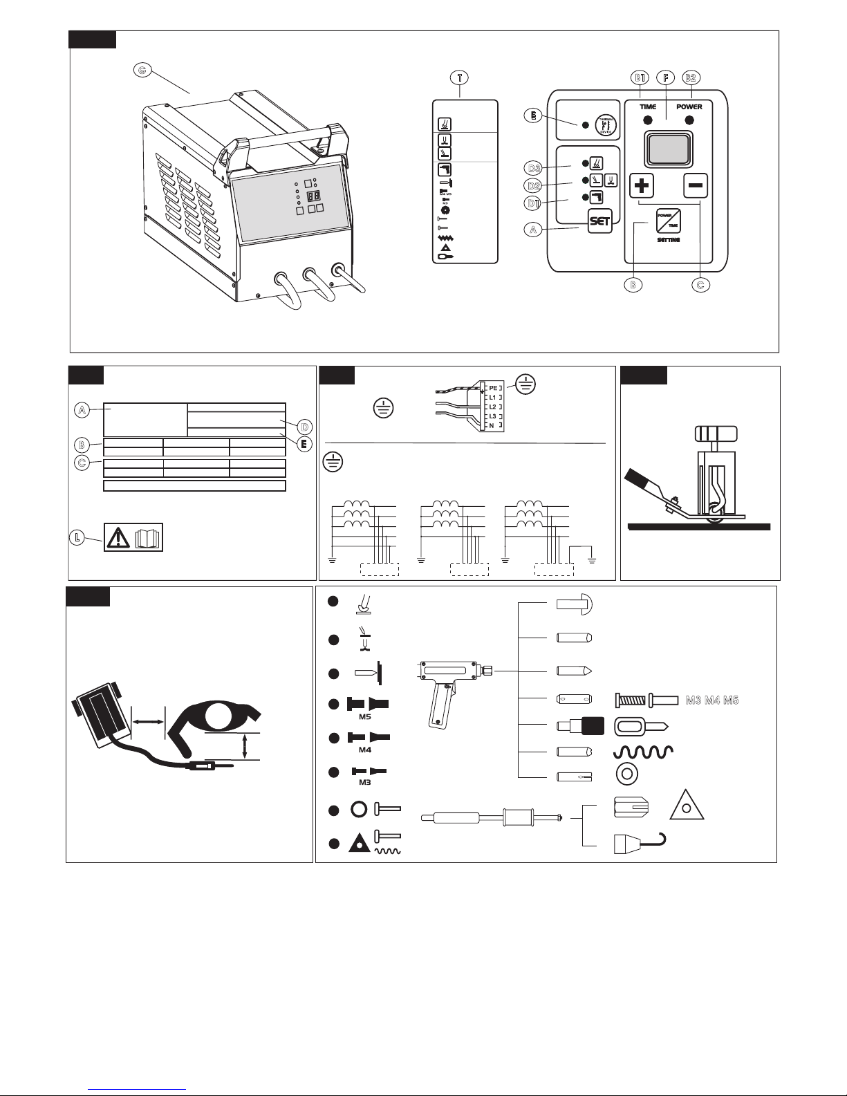
Main parts Fig.1
A) Tool-function selector.
B) Timer/power switch on display.
C) Timer/power increasing/decreasing values
D1) Studder.
D2) Plate heater.
D3) Patching.
E) Heat cut-out signal (resets automatically).
B1) Timer display
B2) Power display
F) Timer/power display
G) ON / OFF switch
Technical data
A data plate is afxed to the welding machine. Fig. 2 shows an example of this plate.
A) Constructor name and address
E) European reference standard for the construction and safety of welding equipment.
B) Symbol of delivered current: alternate / frequency.
U20 Minimum and maximum open circuit voltage (open welding circuit).
I2cc (min imp) Current delivered by the welding machine. (minimum impedance).
I2cc (max imp) Current delivered by the welding machine. (maximum impedance).
I2p Current delivered by the welding machine. (duty cycle 100%).
C) Input power required: 1˜ alternate single phase voltage, frequency.
U1N Input voltage.
Sp Installation power (duty cycle 100%).
S50 Installation power (duty cycle 50%).
Mass Weight
D) Serial number.
L) Safety symbols: Refer to Safety Warnings
Starting up
Connections to the mains must be made by expert or qualied personnel.
Make sure that the welding machine is switched off and the plug is not in the power
socket before carrying out this procedure.
Make sure that the power socket that the welding machine is plugged into is protected
by safety devices (fuses or automatic switch) and grounded.
The device must be connected only to a supply system, with an earthed ‘neutral’ lead.
Assembly and electrical connections
¾ Assembly the detached parts found in the packaging.
¾ Check that the electrical supply delivers the voltage and frequency corresponding to
the welding machine and that it is tted with a delayed fuse suited to the maximum
delivered rated current
TN systems Fig.3
¾ Protect by means of automatic circuit breaker (D curve) rated: 25A for 1Ph220/230.
The disconnection time in case of fault must not be higher than 0.4sec (for supply network
having a nominal voltage to earth of 230V) and should be evaluated at the installation:
if, due to installation conditions, the fault current becomes too low to properly operate
the circuit breaker, the use of an additional RCD (residual current device) may become
necessary (not on TN-C systems).
TT systems Fig.3
¾ According to IEC 60364-4-41 the installation must be protected by an RCD which
sensitivity depends upon the earth connection resistance of each installation, IEC
60364-4-41 also requires that the RCD tripping time is lower than 1sec.
¾ The earth connection resistance of the installation must be considered for the
selection of the RCD sensitivity; the maximum resistance of the protective bonding
circuit of the welding equipment is: 0.19 Ohm
The requirements set out in the IEC/EN61000-3-12 standard do not apply to this
equipment. If this equipment is connected to low voltage power supply network, either
the installer or the user is responsible for checking that this can be done (consult the
distribution system operator if required).
L The requirements set out in the IEC/EN61000-3-12 standard do not apply to this
equipment. If this equipment is connected to low voltage power supply network, either
the installer or the user is responsible for checking that this can be done (consult the
distribution system operator if required).
L In order to comply with the requirements set out in EN61000-3-11 (Flicker), it is
advisable to connect the welder to the supply mains interface points with a service
current capacity of >/= 100A per phase.
L Either the installer or the user is responsible for checking that the welder can be
properly connected; (consult the electrical grid operator if required).
¾ Plug. If the welding machine is not tted with a plug, t a normalised plug (2P+T for
1Ph) of suitable capacity to the power cable Fig.3.
Welding process
Once you have put the welding machine into operation, switch it on and carry out the
adjustments following the order shown in the description of the controls FIG.1
Studder: tecnique for use
¾ Firmly connect the copper bar to a part of the element being repaired, screwing or
clamping it on or welding a washer to the piece and using the terminal clamp as in
the g. 4.
L For repairing doors or cases, it is necessary to connect the copper bar to the part, to
prevent current from passing through the hinges.
¾ Adjust power and time (C) for the desired operation following the values given in table
(T) on g.1
Spot welding and washer, nail, rivet traction (D1)
Sheet heating and overturning (D2)
Patching (D3)
L In this function the pause time is xed (approx. 0.5 sec.)
Thermal cutout signal (E)
The warning light switched on means that the thermal protections of the welder or of the
studder torch are running.
Maintenance
Switch off the welder and remove the plug from the power socket before carrying out any
maintenance operations.
STUDDER.
Torch = check that there are no cuts or abrasions in the cable that bare the internal
conductors.
Earth = check the efciency of connections and terminal.
Extraordinary maintenance to be carried out by expert staff or qualied electrical
mechanics periodically depending on use.
• Inspect the inside of the welder and remove any dust deposited on the electrical parts
(using compressed air) and the electronic cards (using a very soft brush and appropriate
cleaning products). • Check that the electrical connections are tight and that the insulation
on the wiring is not damaged.
 Loading...