

Page 1

VR315andVR325MonochromeMonitors
ServiceGuide
Order Number EK-VR315-SV-002
Digital Equipment Corporation
Page 2

Second Edition, February 1991
The information in this document is subject to change without notice and should not
be construed as a commitment by Digital Equipment Corporation. Digital Equipment
Corporation assumes no responsibility for any errors that may appear in this document.
The software described in this document is furnished under a license and may be used or
copied only in accordance with the terms of such license.
No responsibility is assumed for the use or reliability of software on equipment that is not
supplied by Digital Equipment Corporation or its affiliated companies.
Restricted Rights: Use, duplication, or disclosure by the U. S. Government is subject to
restrictions as set forth in subparagraph ( c) ( 1) ( ii) of the Rights in Technical Data and
Computer Software clause at DFARS 252.227–7013.
Copyright © Digital Equipment Corporation 1991
All Rights Reserved.
Printed in U.S.A.
The following are trademarks of Digital Equipment Corporation:
DEC DIBOL UNIBUS
DEC/CMS EduSystem VAX
DEC/MMS IAS VAXcluster
DECnet MASSBUS VMS
DECsystem–10 PDP VT
DECSYSTEM–20 PDT
DECUS RSTS
DECwriter RSX
dt
This document was prepared and published by Educational Services Development and
Publishing, Digital Equipment Corporation.
Page 3

Contents
About This Manual vii
1 Overview
1.1 Product Description ................................ 1–1
1.1.1 Model Variations ................................ 1–2
1.2 Tools and Equipment ............................... 1–2
1.3 Recommended Spare Parts List ....................... 1–3
2 Troubleshooting
2.1 Before You Start. . . ................................ 2–1
2.2 Troubleshooting Procedures . . ........................ 2–2
2.3 Troubleshooting Tables.............................. 2–2
3 Removing and Replacing FRUs
3.1 Introduction ...................................... 3–1
3.1.1 Removing the External Cables ...................... 3–2
3.1.2 Removing the Rear Cover . ........................ 3–3
3.1.3 Removing the Top Cover . . ........................ 3–4
3.2 Field Replaceable Units (FRUs)....................... 3–5
3.2.1 Interconnect Cable ............................... 3–6
3.2.2 Power Supply Module ............................ 3–8
3.2.3 Discharging the CRT and Removing the Anode Cap ..... 3–10
3.2.4 Deflection Module ............................... 3–12
3.2.5 Video Casting Assembly . . . ........................ 3–16
3.2.6 CRT/Chassis Assembly............................ 3–20
3.3 CRT Disposal (Trained Service Personnel Only) . . . ....... 3–21
3.4 Tilt-Swivel Base . . ................................ 3–24
iii
Page 4

iv Contents
4 Aligning the Video Monitor
4.1 Introduction ...................................... 4–1
4.1.1 Before You Start . ................................ 4–1
4.1.2 Check LEDs and Heater Filament................... 4–4
4.1.3 Displaying Screen Tests . . . ........................ 4–4
4.2 Monitor Adjustments ............................... 4–5
4.3 Deflection Adjustments ............................. 4–6
4.3.1 Raster Adjustment ............................... 4–6
4.3.2 Anode Voltage Adjustment . ........................ 4–6
4.3.3 Height and Width Adjustments ..................... 4–6
4.4 Using the Radiance Meter . . . ........................ 4–8
4.5 Cutoff Adjustment . ................................ 4–10
4.6 GAIN Adjustment . ................................ 4–11
A VR315 and VR325 Documentation
Figures
1–1 Monochrome Monitor ............................... 1–1
3–1 Removing Cables from the Monitor .................... 3–2
3–2 Rear Cover Removal ............................... 3–3
3–3 Top Cover Removal ................................ 3–4
3–4 Field Replaceable Units ............................. 3–5
3–5 Disconnecting the Interconnect Cable . . . ............... 3–7
3–6 Removing the On/Off Switch Cable from the Power Supply . . 3–8
3–7 Removing the Power Supply . ........................ 3–9
3–8 Discharging the CRT and Removing the Anode Cap ....... 3–11
3–9 Loosening the Captive Screw . ........................ 3–13
3–10 Disconnecting Cables from the Deflection Module . . ....... 3–14
3–11 Removing the Deflection Module ...................... 3–15
3–12 Removing Cables from the Video Casting ............... 3–17
3–13 Removing the CRT Socket Connector ................... 3–18
3–14 Removing the Video Casting . ........................ 3–19
3–15 Crushing the Evacuation Point ....................... 3–23
3–16 Tilt-Swivel Base . . ................................ 3–25
4–1 User Controls and Indicator . . ........................ 4–3
Page 5

Contents v
4–2 Circle-Crosshatch Pattern . . . ........................ 4–4
4–3 Using the Metric Measuring Tape ..................... 4–5
4–4 Internal Controls . . ................................ 4–7
4–5 Radiance Meter . . . ................................ 4–9
4–6 Using the Radiance Meter . . . ........................ 4–10
4–7 GAIN, G2, and FOCUS (G4) Adjustments .............. 4–11
Tables
1–1 Tools and Equipment ............................... 1–2
1–2 Recommended Spare Parts. . . ........................ 1–3
2–1 Blank Screen, No Video or Raster ..................... 2–3
2–2 Blank Screen, No Video, but Raster is Present ........... 2–5
2–3 Poor Display Quality ............................... 2–6
4–1 Monitor Controls and Indicators ...................... 4–2
Page 6

Page 7

AboutThisManual
VR315 and VR325 Video Monitors
This guide describes how to service the VR315 and VR325 monochrome
monitors in the field.
Manual Organization
This manual is organized as follows:
• Chapter 1 provides a general overview of the product and includes a
list of spare parts.
• Chapter 2 describes the troubleshooting procedures.
• Chapter 3 provides the removing and replacing procedures for the
Field Replaceable Units (FRUs).
• Chapter 4 describes the alignment procedures.
• Appendix A describes related documentation.
Conventions
Convention Meaning
Caution Provides information to prevent damage to the equipment.
Warning Provides information that relates to personal safety.
Note Provides general information.
PN Refers to a part number.
!
monitor Refers to the VR315 and VR325 monochrome monitors.
This type of number in text refers to an item in an illustration.
vii
Page 8

Page 9
1
Overview
1.1 Product Description
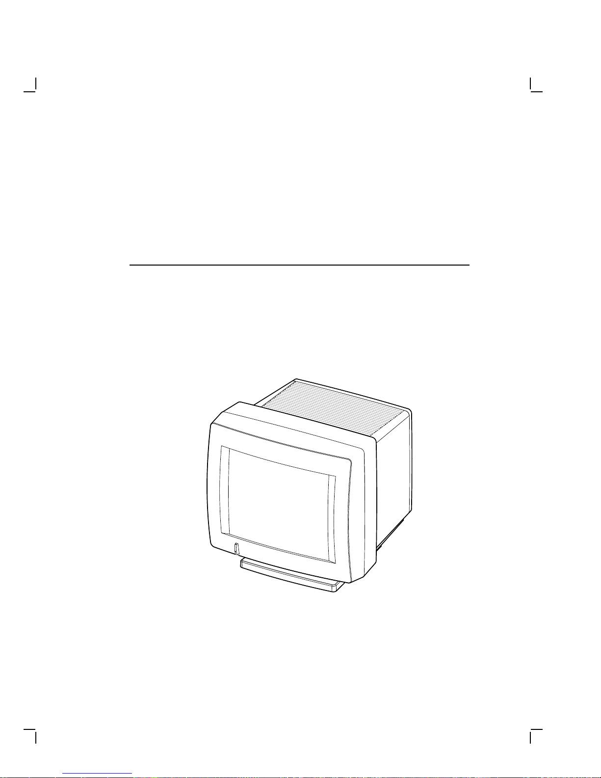
The monochrome monitor (Figure 1–1) has a direct viewed antiglare
screen with an auto-ranging power supply for worldwide operation. Its
built-in tilt-swivel base lets the user adjust the screen for viewing comfort.
When connected to a host system, the monitor displays information sent
by the host.
Figure 1–1 Monochrome Monitor
MA-0299-90.DG
1–1
Page 10

1–2 Overview
1.1.1 Model Variations
The monitor is available in the following models:
Model Applicable Area
VR315-DA Northern hemisphere
VR315-D4 Southern hemisphere
VR325-DA Northern hemisphere
VR325-D4 Southern hemisphere
1.2 Tools and Equipment
Table 1–1 lists the tools and equipment you will need to service the
monitor:
Table 1–1 Tools and Equipment
Tools and Equipment Part Number
Terminal technician tool kit 29-27340-01
Static protection kit 29-26246-00
Anode discharge tool 29-24717-00
Metric measuring tape 29-25342-00
Safety goggles 29-16141-00
Gloves 29-16146-00
Page 11

Overview 1–3
1.3 Recommended Spare Parts List
Table 1–2 lists the recommended spare parts for the monitor.
Table 1–2 Recommended Spare Parts
VR315 Part
Spare Part
Power supply 54-19629-02 54-19629-03
Deflection module 54-19826-01 54-19826-02
Video casting assembly 70-27073-01 70-27073-01
Module interconnect cable 70-27000-02 70-27000-02
CRT/chassis assembly
Northern Hemisphere 70-27477-01 70-27481-03
Southern Hemisphere 70-27477-02 70-27481-04
Number
VR325 Part
Number
Page 12

Page 13

2
Troubleshooting
This chapter describes how to troubleshoot a monitor problem through
fault isolation.
2.1 Before You Start
The following information will help you troubleshoot the monitor easily
and effectively:
WARNING
If you smell burning components, press the monitor power switch
off and disconnect the power cord.
• If you are going to service a display quality type of problem, tell the
customer to warm the monitor up for at least 20 minutes, if possible,
before you arrive and begin the troubleshooting procedures.
• Magnetic fields affect monitor performance and can give a false
indication of a monitor failure. Place the monitor away from any
electromagnetic devices such as printers and terminals, or away from
large magnetized objects such as filing cabinets and steel beams in
walls.
NOTE
Any time you replace a video casting assembly, deflection module,
or power supply module, perform all the necessary adjustments.
Refer to Chapter 3.
2–1
Page 14

2–2 Troubleshooting
2.2 Troubleshooting Procedures
These procedures assume that only one assembly has failed or only one
problem exists. Always troubleshoot the most obvious symptom first;
however, one symptom may indicate multiple failures. Problems may
come from either the host system or the monitor.
Troubleshoot the monitor as follows:
1. Ask the operator to describe the problem. The operator often is the
most knowledgeable.
2. Identify the problem. The screen display often indicates which
problem is occurring.
3. Isolate the problem. Refer to the troubleshooting tables (Section 2.3)
to find the suggested solutions.
4. Display the host system alignment test patterns to make sure that
no other problem exists. Refer to the host system service guide for
displaying test patterns.
2.3 Troubleshooting Tables
The troubleshooting tables list the possible cause in order of probability.
This troubleshooting information applies to three types of video problems
that the monitor may exhibit:
• A blank screen, without video or raster (Table 2–1)
• A blank screen, without video, but raster present (Table 2–2)
• Poor display quality (Table 2–3)
Use the troubleshooting tables as follows:
1. Note the symptom of the problem.
2. Check the Symptom column for a match.
3. Check the conditions in the Possible Cause column in the order given.
4. Perform the action in the Suggested Solution column in the order
given.
Page 15

Troubleshooting 2–3
Table 2–1 Blank Screen, No Video or Raster
Symptom Possible Cause Suggested Solution
Blank screen, no video
or raster. Power to
the monitor is on (the
power switch is in) but
the power indicator
light is off.
No video or raster, but
the power indicator is
on.
The power cord is
not connected to
the power source or
monitor.
Low or no power at
wall outlet.
Power supply
module is faulty.
Deflection module
is faulty.
Video module is
faulty.
Brightness or
contrast is set
incorrectly.
Power to the host
system is not on.
Host signal cable is
disconnected.
Connect the power cord to the
power source or monitor.
Use another wall outlet. If
the problem continues, call the
facilities person.
Replace the power supply
module (Section 3.2.2).
Replace the deflection module
(Section 3.2.4).
Replace the video casting
assembly (Section 3.2.5).
Adjust the brightness and
contrast controls.
Turn power to the host system
on.
Connect the signal cable to the
monitor and host.
Page 16

2–4 Troubleshooting
Table 2–1 (Cont.) Blank Screen, No Video or Raster
Symptom Possible Cause Suggested Solution
No video or raster, but
the power indicator
and LED on the
deflection module are
on.
No video or raster, but
the power indicator
LED is on; the
deflection module
LED is off.
Deflection module
is faulty.
Video casting
assembly is faulty.
CRT/chassis
assembly is faulty.
Internal cabling is
loose or faulty.
G2 Bias is set
incorrectly.
Signal cable is
faulty.
Deflection module
is faulty.
Deflection module
is faulty.
Replace the deflection module
(Section 3.2.4).
Replace the video casting
assembly (Section 3.2.5).
Replace the CRT/chassis
assembly (Section 3.2.6)
only after trying the previous
solutions.
Check all cabling going to
the deflection module and
the video casting assembly,
including the CRT socket
connector. If necessary, secure
the cables.
Correct the G2 adjustment.
(Section 4.5).
Replace the signal cable.
Refer to the host system
documentation.
Replace the deflection module
(Section 3.2.4).
Replace the deflection module
(Section 3.2.4).
Page 17

Troubleshooting 2–5
Table 2–2 Blank Screen, No Video, but Raster is Present
Symptom Possible Cause Suggested Solution
Raster can be
displayed by
adjusting the
brightness control,
but no video or
cursor can be seen
even when the
contrast control is
at maximum.
The Host system
CRT screen saver
feature is activated.
Internal cabling is
loose or faulty.
The host system
is not supplying
video signals to the
monitor.
Host system is
faulty.
Video casting
assembly is faulty.
Deflection module is
faulty.
Faulty CRT/chassis
assembly
Press any key to reactivate the
display.
Check all the cables to the
deflection module and the
video casting assembly.
Connect the monitor to a
known working host system (if
available) to verify the problem
before replacing any monitor
modules.
Repair the host system.
Replace the video casting
assembly (Section 3.2.5).
Replace the deflection module
(Section 3.2.4).
Replace the CRT/chassis
assembly (Section 3.2.6)
only after trying the previous
solutions.
Page 18

2–6 Troubleshooting
NOTE
Make sure the monitor has warmed up for at least 20 minutes
before you use Table 2–3.
Table 2–3 Poor Display Quality
Symptom Possible Cause Suggested Solution
Poor geometry,
centering, height,
width, and/or
linearity.
Poor light output
(using the all-white
diagnostic pattern).
The Display is not
bright enough.
Controls on top of the
monitor are out of
adjustment.
Local magnetic fields. Remove any electro-
Monitor is out of
adjustment.
Deflection module is
faulty.
CRT/chassis assembly
is faulty.
The brightness or
contrast control is set
incorrectly.
Host system is not
supplying correct
signal levels.
GAIN and Cutoff
adjustments may be
incorrect.
Video casting
assembly is faulty.
Deflection module is
faulty.
See section 4.1.
mechanical devices from
the vicinity of the monitor, or
move the monitor to another
location.
Perform the alignment
procedure. Refer to Chapter
4.
Replace the deflection module
(Section 3.2.4).
Replace the CRT/chassis
assembly (Section 3.2.6) only
after trying the previous
solutions.
Adjust the brightness and
contrast controls.
Repair the host system.
Perform the GAIN
adjustment (Section 4.6)
and the Cutoff adjustment
(Section 4.5).
Replace the video casting
assembly (Section 3.2.5).
Replace the deflection module
(Section 3.2.4).
Page 19

Troubleshooting 2–7
Table 2–3 (Cont.) Poor Display Quality
Symptom Possible Cause Suggested Solution
CRT is worn out. Replace the CRT/chassis
Display is too bright. Brightness control is
Vertical lines are not
straight.
Video noise (Display
has intermittent
flashing or changes
in brightness.)
Focus is not sharp. Adjustment is
set incorrectly.
Video casting
assembly is faulty.
Deflection module is
faulty.
Local magnetic fields
are present.
Deflection module is
faulty.
Faulty CRT/chassis
assembly
The signal cable is
loose or faulty.
Video casting
assembly is faulty.
Deflection module is
faulty.
Power supply module
is faulty.
Host system is faulty. Repair the host system.
incorrect.
Deflection module is
faulty.
assembly (Section 3.2.6) only
after trying the previous
solutions.
Set the brightness control to
the optimum range.
Replace the video casting
assembly (Section 3.2.5).
Replace the deflection module
(Section 3.2.4).
Remove any electromechanical devices from
the vicinity of the monitor, or
move the monitor.
Replace the deflection module
(Section 3.2.4).
Replace the CRT/chassis
assembly (Section 3.2.6) only
after trying the previous
solutions.
Reseat the connectors or
replace the signal cable.
Replace the video casting
assembly (Section 3.2.5).
Replace the deflection module
(Section 3.2.4).
Replace the power supply
module (Section 3.2.2).
Perform the FOCUS
adjustment (Section 4.5).
Replace the deflection module
(Section 3.2.4).
Page 20

2–8 Troubleshooting
Table 2–3 (Cont.) Poor Display Quality
Symptom Possible Cause Suggested Solution
Video casting
assembly is faulty.
CRT/chassis assembly
is faulty.
Replace the video casting
assembly (Section 3.2.5).
Replace the CRT/chassis
assembly (Section 3.2.6) only
after trying the previous
solutions.
Page 21

3
RemovingandReplacingFRUs
3.1 Introduction
This chapter describes how to remove and replace the monitor field
replaceable units (FRUs).
The monitor consists of a small number of removable FRUs that are easily
accessed and removed from the rear of the monitor. No special tools are
needed, and self-retaining hardware is used.
The procedures describe how to remove the FRUs. To install each FRU,
do the reverse of the removal procedure.
WARNING
Turn power to the monitor off before performing any of these
procedures.
NOTE
Before removing any FRUs, you must remove the rear cover and
the top cover.
3–1
Page 22

3–2 Removing and Replacing FRUs
3.1.1 Removing the External Cables
Remove the external cables (Figure 3–1) as follows:
1. Make sure the power switch is off (out).
2. Unplug the power cord from the power source (wall outlet or host
system) first, then from the monitor.
3. Remove the signal cable from the rear of the monitor.
NOTE
Push the connector in and rotate it to the left until the signal
cable is released from the connector.
Power Cord
Power Source
From Host System
Figure 3–1 Removing Cables from the Monitor
MA-0225-90.DG
Page 23

Removing and Replacing FRUs 3–3
3.1.2 Removing the Rear Cover
Remove the rear cover as follows:
1. Remove the external cables (Section 3.1.1).
2. Use a Phillips screwdriver to remove the four screws that hold the
rear cover to the enclosure (Figure 3–2).
3. Remove the rear cover by pulling the cover towards you.
Figure 3–2 Rear Cover Removal
MA-0226-90.DG
Page 24

3–4 Removing and Replacing FRUs
3.1.3 Removing the Top Cover
Remove the top cover as follows:
1. Remove the rear cover (Section 3.1.2).
2. Tilt the top cover up and slide it toward the rear of the monitor.
(Figure 3–3).
Top
Cover
Figure 3–3 Top Cover Removal
MA-0227-90.DG
Page 25

Removing and Replacing FRUs 3–5
3.2 Field Replaceable Units (FRUs)
The monitor FRUs are shown in Figure 3–4.
When replacing any FRU, tilt the monitor from the back to the front to
allow easier access to the modules.
WARNING
Turn the power off before disconnecting or replacing any FRU.
CRT Chassis
Assembly
Deflection
Module
Figure 3–4 Field Replaceable Units
Interconnect
Cable
Video Casting
Assembly
Power
Supply
MA-0228-90.DG
Page 26

3–6 Removing and Replacing FRUs
3.2.1 Interconnect Cable
Remove the interconnect cable as follows:
1. Remove the rear cover (Section 3.1.2).
2. Remove the top cover (Section 3.1.3).
3. Disconnect the interconnect cable in the following order (Figure 3–5).
FRU Connector Interconnect Cable Plug
Power supply (right) J1 P1
Video casting (center) J2 P2
Deflection module (left) J3 P3
!
"
#
Page 27

Removing and Replacing FRUs 3–7
CAUTION
When replacing the interconnect cable, verify that the pull tab
(labeled P2) is above the cable connector on the deflection module.
You can damage the monitor if this cable is replaced incorrectly.
Figure 3–5 Disconnecting the Interconnect Cable
2
3
Interconnect
Cable
MA-0229-90.DG
1
Page 28

3–8 Removing and Replacing FRUs
3.2.2 Power Supply Module
Remove the power supply module as follows:
1. Remove the rear cover (Section 3.1.2).
2. Remove the top cover (Section 3.1.3).
3. Remove the interconnect cable (Section 3.2.1).
4. Disconnect the 3-wire, 5-pin On/Off switch cable (P4) from the
connector (J4) at the top of the power supply by pressing the tab
on top of the connector (Figure 3–6).
3-Wire, 5-Pin,
On/Off Switch
Cable
Power
Supply
Figure 3–6 Removing the On/Off Switch Cable from the Power Supply
MA-0230-90.DG
Page 29

Removing and Replacing FRUs 3–9
5. Loosen the captive screw that holds the power supply to the chassis
(Figure 3–7).
6. Slide the power supply module out of the card guides.
Power
Supply
Figure 3–7 Removing the Power Supply
MA-0231-90.DG
Page 30

3–10 Removing and Replacing FRUs
3.2.3 Discharging the CRT and Removing the Anode Cap
Discharging the CRT is a process that drains to ground any leftover
voltages that remain in the extra-high tension (EHT) cable after power is
removed. Discharge the CRT as follows:
1. Remove the rear cover (Section 3.1.2).
2. Remove the top cover (Section 3.1.3).
3. Remove the interconnect cable (Section 3.2.1).
4. Remove the power supply module (Section 3.2.2).
WARNING
The following steps expose you to the CRT anode which may
store a high voltage.
5. Attach the clip end of the anode discharge tool (PN 29-24717-00) to a
chassis ground point near the CRT anode.
WARNING
Keep your free hand away from any part of the monitor during
the anode discharge process.
6. Using one hand, carefully slip the anode discharge tool under the CRT
anode connector cup until it touches the connector prongs. Maintain
contact for at least 10 seconds.
NOTE
Be careful when you use the anode discharge tool. Do not tap
the CRT. Avoid scratching or marring the CRT glass when you
insert or remove the tool.
7. Remove the CRT anode cap from the CRT, as shown in Figure 3–8.
Page 31

Removing and Replacing FRUs 3–11
A. Push in the direction
of the arrow.
B. When one barb is free
push in the opposite
direction (see arrows)
to remove anode cap.
,
MA-0232-90.DG
Figure 3–8 Discharging the CRT and Removing the Anode Cap
Page 32

3–12 Removing and Replacing FRUs
3.2.4 Deflection Module
Remove the deflection module as follows:
CAUTION
Use a static protection kit (PN 29-26246-00) when handling the
deflection module.
1. Remove the rear cover (Section 3.1.2).
2. Remove the top cover (Section 3.1.3).
3. Remove the power supply module (Section 3.2.2).
4. Discharge the CRT and remove the anode cap (Section 3.2.3).
WARNING
You must complete the discharge procedure for the CRT
(Section 3.2.3) before removing the deflection module.
5. Remove the interconnect cable (Section 3.2.1).
6. Loosen the captive screw that holds the deflection module to the
chassis (Figure 3–9).
7. Remove the 2-wire, 3-pin G2 and Focus cable (P7) from the connector
(J7) at the top of the video casting assembly by pressing on the sides
of the connector and pulling. You may need a small screwdriver to
assist in releasing the tabs.
Page 33

Deflection
Module
Removing and Replacing FRUs 3–13
2-Wire, 3-Pin
Cable
Video
Casting
Assembly
Figure 3–9 Loosening the Captive Screw
6-Wire, 8-Pin
Brightness/
Contrast
Cable
MA-0233-90.DG
Page 34

3–14 Removing and Replacing FRUs
9. Disconnect the 9-wire, 9-pin raster control cable (P6) from the
connector (J6)!at the top of the deflection module by pressing
the tab on top of the connector.
10. Disconnect the multicolored, 6-wire, 9-pin CRT/yoke cable (P11) from
the connector (J11)"on the deflection module by pressing the tabs
on the connector (Figure 3–10).
9-Wire, 9-Pin,
Raster Control
Cable
1
6-Wire, 9-Pin,
6-Wire, 9-Pin,
CRT/Yoke Cable
CRT/Yoke Cable
2
2
Figure 3–10 Disconnecting Cables from the Deflection Module
MA-0234-90.DG
Page 35

Removing and Replacing FRUs 3–15
11. Slide the deflection module out of the card guides (Figure 3–11).
Card
Guide
Deflection
Module
Figure 3–11 Removing the Deflection Module
MA-0235-90.DG
Page 36

3–16 Removing and Replacing FRUs
3.2.5 Video Casting Assembly
Remove the video casting assembly as follows:
1. Remove the rear cover (Section 3.1.2).
2. Remove the top cover (Section 3.1.3).
3. Remove the interconnect cable (Section 3.2.1).
4. Remove the 2-wire, 3-pin cable (P4) from the connector (J4) at the top
of the video casting assembly (Figure 3–12) by pressing on the sides of
the connector and pulling. You may need a small screwdriver to assist
in releasing the tabs.
5. Disconnect the 6-wire, 8-pin brightness/contrast cable (P5) from the
connector (J5) at the bottom of the video casting assembly by pressing
the top center tab on the connector. Place the cable out of the way
behind the video casting.
Page 37

2-Wire, 3-Pin
Cable
Removing and Replacing FRUs 3–17
6-Wire, 8-Pin
Brightness/
Contrast
Cable
MA-0236-90.DG
Figure 3–12 Removing Cables from the Video Casting
6. Gently push the CRT socket connector off the socket pins
(Figure 3–13).
CAUTION
When you install the video casting assembly, carefully push
the CRT socket connector onto the CRT neck. Use care not to
bend the pins during this procedure.
Page 38

3–18 Removing and Replacing FRUs
CRT
Socket
Connector
Socket
Pins
Figure 3–13 Removing the CRT Socket Connector
7. Loosen the captive screw at the top of the video casting (Figure 3–14).
8. Gently pull the top of the video casting assembly towards you and lift
it out of the chassis.
MA-0238-90.DG
Page 39

Removing and Replacing FRUs 3–19
Video Casting
Assembly
Figure 3–14 Removing the Video Casting
MA-0237-90.DG
Page 40

3–20 Removing and Replacing FRUs
3.2.6 CRT/Chassis Assembly
To disassemble the CRT/chassis assembly:
1. Remove the rear cover (Section 3.1.2).
2. Remove the top cover (Section 3.1.3).
3. Remove the interconnect cable (Section 3.2.1)
4. Remove the power supply module (Section 3.2.2)
5. Discharge the CRT and remove the anode cap (Section 3.2.3).
WARNING
You must discharge the CRT and remove the anode cap
(Section 3.2.3) before removing the deflection module.
6. Remove the deflection module (Section 3.2.4)
7. Remove the video casting assembly (Section 3.2.5)
NOTE
After removing the above FRUs, the remaining part is the
CRT/chassis assembly.
Page 41

Removing and Replacing FRUs 3–21
3.3 CRT Disposal (Trained Service Personnel Only)
This section describes how to safely dispose of the monitor cathode-ray
tube (CRT). CRTs are glass vacuum tubes. Because air pressure outside
the tube is greater than air pressure inside, there is always the possibility
of accidental implosion.
WARNING
You must handle CRTs very carefully to avoid accidental
implosion and shattering glass. Use the following guidelines
and disposal procedure to remove and dispose of a CRT. These
guidelines and procedure are Digital policy for all CRTs with
more than three inches in diameter.
NOTE
This procedure supersedes all other tech tips about replacing
and disposing of CRTs. This procedure is for Digital personnel
only, and is not intended for use by OEM and self-maintenance
customers.
Location
Work in areas where risks and exposure are limited to trained Digital
personnel. Only Digital personnel should be in the area during CRT
removal and replacement.
Handling a CRT
• Never handle the CRT by the neck. Always use two hands and hold
the CRT by the sides near the face of the tube.
• Keep the CRT away from your body during handling.
• Do not let the neck strike anything.
• Do not rest the CRT on its neck.
• Do not let the CRT touch any tools, such as screwdrivers and soldering
irons.
Stocking and Storage
All CRTs must be kept in a closed container or mounted in the device
cabinetry.
CRT Disposal
Use the following procedure to safely dispose of CRTs. Always perform
this procedure at a Digital facility.
Page 42

3–22 Removing and Replacing FRUs
WARNING
Do not dispose of any CRT until it is rendered inoperative and
safe to dispose.
Never perform the following disposal procedure at the customer
site. Return the defective CRT to the local Digital facility for
disposal.
At the Digital facility you must:
• Clear the area of nonessential personnel.
• Have a second person in the area in case of an emergency.
• Wear safety goggles (PN 29-16141-00).
• Wear gloves (PN 29-16146-00).
• Use pliers.
WARNING
To avoid injury to your eyes or hands, always wear goggles
and gloves when you work with a CRT. Never handle pieces of
phosphor-coated glass without wearing protective gloves.
Before you perform the following procedure, remove the FRUs listed in
Section 3.2.6.
1. Place the old CRT/chassis assembly and the original packing material
in the container from which you removed the new CRT/chassis
assembly.
2. Using pliers, slowly crush, but do not snap, the evacuation point
(Figure 3–15). Do not move or disturb the CRT until the hissing
sound of in-rushing air stops.
CAUTION
Use care not to break the unprotected glass area of the CRT
neck that surrounds the evacuation point.
NOTE
The evacuation point is a protrusion that extends from
the circular area defined by the CRT neck pins. The glass
protrusion is sometimes encased in a protective plastic cap,
and more force is required to crush it.
Page 43

Removing and Replacing FRUs 3–23
Figure 3–15 Crushing the Evacuation Point
3. Seal the carton with packing tape and dispose of it in the Digital site’s
trash receptacle.
NOTE
The safe "gassing" of the CRT is necessary to prevent liability and
safety problems that may arise from accidental CRT implosion.
MA-X0667-88
Page 44

3–24 Removing and Replacing FRUs
3.4 Tilt-Swivel Base
Helpful Hint: During normal use, the tilt-swivel base should not come
off the unit. There is a retainer plug in the center of the swivel retainer
(74-39791-01) to hold the base on. If the tilt-swivel base should come off
and the retainer teeth are not broken, you do not have to take the monitor
apart. Use the following procedure to put the tilt-swivel base back on the
monitor.
1. Place the monitor screen-side down on a soft pad.
2. Align the tilt-swivel base with the wider part downward toward the
screen (Figure 3–16).
3. Place a curved tool, like a long Allen wrench, through the center of
the swivel retainer inside the base.
4. While pressing on the base with one hand, pull the swivel retainer
toward the base until the retainer teeth click into position.
5. Install a retainer plug (74-41176-01) in the retainer to keep the teeth
apart.
Page 45

Removing and Replacing FRUs 3–25
Teeth of
Swivel
Clamp
Monitor
Base
Monitor
(Bottom
View)
Figure 3–16 Tilt-Swivel Base
MA-0239-90.DG
Page 46

Page 47

4
AligningtheVideoMonitor
4.1 Introduction
This chapter describes how to align the monitor display. You do not have
to perform every adjustment procedure each time you align the monitor;
however, you should check all adjustments in the order shown.
The success of one adjustment may depend on the accuracy of the
preceding adjustments with the exception of the FOCUS and G2
adjustments. If a setting is already correct, you can skip that adjustment
and go on to the next one.
Use Section 4.1.1 to set up the monitor for adjustments. You must use
the screen alignment test patterns to make all adjustments. Refer to your
host system documentation to set up test patterns.
4.1.1 Before You Start
NOTE
If a customer calls with a display quality type of problem, ask the
customer to leave the monitor on until you arrive. Then, after
removing the rear cover, only a 5 minute warm-up is needed.
Clean the Monitor
Use a soft tissue or cloth and a non-abrasive, nonflammable glass cleaner,
or use Digital’s video screen cleaner (PN VT3XX-SC).
Set up the Monitor
Before you perform adjustments, set up the monitor as follows:
1. Place the monitor on a nonconductive surface.
2. Remove the rear cover (Section 3.1.2).
3. Remove the top cover (Section 3.1.3).
4. Reconnect the video cable.
4–1
Page 48

4–2 Aligning the Video Monitor
5. Reconnect the power cord.
6. Press the power switch to on. Wait for a video display to appear on
the screen.
7. Verify that the user controls on the top of the monitor are in the
center position of the thumbwheels. The user adjustments are listed
in Table 4–1 and shown in Figure 4–1.
8. Rotate the monitor so the adjustments on the deflection board are on
the right and the screen to view the test pattern is on the left. When
performing the geometry adjustments, the monitor should be facing
east, if possible.
Table 4–1 Monitor Controls and Indicators
Item Control/Indicator Function
!
"
#
$
%
&
'
1
The VR315 has a degauss icon on the bezel because this bezel was planned for use with
a companion color product. The VR315 and VR325 monochrome monitors do not have or
need a degauss switch.
Power switch/
indicator
Contrast Adjusts the video display intensity.
Brightness Adjusts the video background intensity.
Rotation Rotates the video display area.
Horizontal centering Adjusts the horizontal position of the active
Vertical centering Adjusts the vertical position of the active
Degauss switch Not installed
Turns the power on and off. When the power
is on, the switch is lit up. For extended
monitor life, switch the power off when not
in use.
area with respect to the bezel.
area with respect to the bezel.
1
.
Page 49

Aligning the Video Monitor 4–3
4
1
2
3
7
5
6
Figure 4–1 User Controls and Indicator
MA-1295-89.DG
Page 50

4–4 Aligning the Video Monitor
4.1.2 Check LEDs and Heater Filament
Visually check the monitor to ensure that the following components are
ON:
• LED on the power switch
• LED on the deflection module
• CRT heater filament
4.1.3 Displaying Screen Tests
The procedures in this chapter refer to a circle-crosshatch alignment test
pattern (Figure 4–2) and an all-white test pattern. Display them on the
screen as needed by using procedures for your host system.
Refer to the host system service guide for accessing these diagnostic
screen patterns.
Figure 4–2 Circle-Crosshatch Pattern
MA-X0889-88
Page 51

Aligning the Video Monitor 4–5
4.2 Monitor Adjustments
Let the monitor warm up for at least 20 minutes before performing any
adjustments. The warm-up time ensures that the circuitry is at a stable
temperature before you do any adjustments.
NOTE
In the following steps, use a metric measuring tape (PN 29-25342)
to measure the dimensions of the screen display. To avoid
scratching the screen with the tape’s metal clip, start the
measurement at 10 cm. See Figure 4–3.
10 119
199 mm
VR315 - 236 mm
VR325 - 265 mm
Figure 4–3 Using the Metric Measuring Tape
MA-0301-90.DG
LJ-00545-TI0
Page 52

4–6 Aligning the Video Monitor
4.3 Deflection Adjustments
4.3.1 Raster Adjustment
1. Set the user controls (Figure 4–1) on the top and the bottom of the
monitor in the center position of the thumbwheels.
2. Adjust the Contrast control just until the raster displays.
3. Adjust the G2 potentiometer to its centered position (Figure 4–4).
4. Adjust VLIN potentiometer to its centered position.
5. Using a hex-head driver, set HLIN for the maximum width of the
raster, then reduce the raster size by about 5 mm.
4.3.2 Anode Voltage Adjustment
The anode voltage affects the overall display size, both the height and the
width of the display. Only the center region of the potentiometer affects
the display size. Adjust the anode voltage as follows:
1. Mark the position on the ANODE potentiometer where the display
size is maximized and minimized, by turning it in one direction and
then the other.
2. Set the ANODE potentiometer to the half-way point between where
the display size was at a maximum and at a minimum.
4.3.3 Height and Width Adjustments
Check and adjust linearity as follows:
1. Display the circle-crosshatch pattern (Figure 4–2).
2. Set the Brightness control on the bottom of the monitor to display the
raster.
3. Set the HPHASE potentiometer so that video display is centered in
the raster.
4. Using a Phillips screwdriver, adjust HCEN to center the display in
the bezel.
5. Using a hex-head driver, set WIDTH so that the right half of the
display is the correct width.
6. Using a hex-head driver, set HLIN so that the left half of the display
is correct.
Page 53

Aligning the Video Monitor 4–7
7. Repeat step 4 until the correct size, centering, and linearity is
obtained. Then continue with step 8.
Width
HLin
HLin
HCen
GainGain
G2
Focus (G4)
Anode
HPhase
VCen
VLin
Height
VHold
Figure 4–4 Internal Controls
8. Adjust VCEN (Figure 4–4) so that the display is centered in the bezel.
9. Set HEIGHT so that the center to the bottom half of the dimension is
correct.
10. Adjust VLIN so that the center rectangles are the same size as the
bottom and top rectangles.
MA-0471-90.dg
Page 54

4–8 Aligning the Video Monitor
4.4 Using the Radiance Meter
Use the radiance meter as follows:
1. Remove the cap from the radiance meter sensor head and connect the
occluder to the radiance meter (Figure 4–5).
CAUTION
Avoid excessive force when tightening the occluder or you may
damage the radiance meter. Do not touch the exposed filter
after the protective cap is removed.
2. Connect the ac line adapter to the radiance meter and plug the
adapter into a wall outlet.
NOTE
Ensure that your radiance meter is in calibration.
3. Turn the power switch to on.
NOTE
Do not use the POWER ON W/BACKLIGHT position when you
are using the radiance meter with batteries.
4. Set the range switch to the second position from the top (1.999).
Page 55

Aligning the Video Monitor 4–9
Occluder
Sensor
Head
Power
Switch
Range
Switch
AC Adapter
AC Adapter
Connector
MA-X0665-88A
Figure 4–5 Radiance Meter
5. Place the occluder firmly against the center of the screen (Figure 4–6).
Take a red china pencil to draw an arc or circle around the occluder.
NOTE
You must take all meter readings with the meter centered in
this arc or circle.
Page 56

4–10 Aligning the Video Monitor
MA-0302-90.DG
Figure 4–6 Using the Radiance Meter
4.5 Cutoff Adjustment
To adjust G2 control, use the radiance meter on the screen (Figure 4–6).
Check and adjust G2 (Figure 4–7) as follows:
1. Set the Brightness to minimum and Contrast controls to maximum.
2. Set G2 using the raster pattern so that the maximum background
luminance is 0.010.
3. Display the Circle/Crosshatch pattern and set FOCUS (G4) for best
overall sharpness.
Page 57

Aligning the Video Monitor 4–11
4.6 GAIN Adjustment
1. Set the Contrast control to maximum and Brightness control for
background extinction.
2. Set GAIN using the All-White pattern to obtain 0.283 luminance at
the screen center.
G2
G4
Gain
Figure 4–7 GAIN, G2, and FOCUS (G4) Adjustments
MA-0300-90.DG
Page 58

Page 59

A
VR315andVR325Documentation
You can order the following VR315 and VR325 documents, some of which
are available in several languages, from Digital. Contact your sales
representative for availability and more information.
Installing and Using the VR315 and VR325 Monochrome Monitors
EK-VR315-IN-002
This guide provides users with the information needed to install, operate,
and maintain the VR315 and VR325 monitors. The manual also describes
all controls and indicators.
VR315/VR325 Monochrome Monitor IPB
EK-VR315-IP-002
This document provides a detailed parts breakdown of the VR315 and
VR325 field replaceable parts. The documents do not contain part
numbers for components on the printed circuit modules. However,
these components are listed in the Field Maintenance Print Set, ordered
separately.
VR315 Field Maintenance Print Set
MP-03013-01
This document provides a complete set of electrical and mechanical
schematic diagrams for the VR315 monitor.
VR325 Field Maintenance Print Set
MP-03013-02
This document provides a complete set of electrical and mechanical
schematic diagrams for the VR325 monitor.
A–1
Page 60

 Loading...