

Page 1

EK-VSM40-OM-002
VAXstation
3100
Model
48
Owner's
Manual
digital
equipment
corporation
maynard,
massachuseits
Page 2

July
19{K>
The
informationinthis
documentissubjecttochange
without
notice
and
should
not
be
construed
as a commitanent by Digital
Equipment
Corporation.
Digital
Equipment
Corporation
assumes
no
responsibility
for
any
errors
that
may
appearinthis
document.
Any
software
described
in
this
documentisfurnished
underalicense
and
may
be
usedorcopied onlyinaccordance
with
the
termsofsuch
license. No responsibility is
assumed
for
i^e
use
or reliability of software
or
equipment
thatisnot
supplied by Digital
Equipment
Cozporataon or
its
affiliated
companies.
Restricted
Rights:
Use,
duplication,
or
disclosure
by
the
U.S.
Giovemmentissubjecttorestrictions
as
set
forth
in
siibparagraph
(c)(l)(ii) ofthe
Rightsin'Technical
Data and
Computer
^ftware dause
at
DFARS
252.227-7013.
©
Digital
Equipment
Corporation
1990.
All
rights
reserved.
Printed
in
U.S.A.
The
postpaid
Reader's
Comments
formsatthe
endofthis
document
request
your
critical
evaluation
to
assist
in
preparing
future
docximentation.
The
following
are
trademarks
of
Digital
Equipment
Corporation:
CompacTape, DDIF,
DEC,
DECconnect,
DECnet,
DECUS,
DECwindows,
DELNI,
DEMPR,
Desktop-VMS,
DEMPR,
DESNC,
DSS, INTERNET,
LA75 Companion
Printer,
LN03, LN03R
ScriptPrinter,
MASSBUS,
PrintServer,
Q-bus,
ReGIS,
Remote
System
Manager,
RRD40,
ThinWire,
ULTRDC, UNEBUS, VAX, VAX DOCUMENT, VAXcluster, VAXpc,
VAXserver,
V^Xstation,
VMS,
VT,
XUI,
and
the
DIGITAL Logo
MS®, Microsoft®,
and
MS-DOS®
are
registered
trademarks
of
Microsoft
Coiporation.
NFS'"'isa
trademark
of
Sun
Microsystems,
Inc. IBM®
and
IBM
Personal
Computer
AT®
are
registered
trademarks
of
International
Business
Machines
Corporation.
Pos^cbipi® is a registered trademark
of
Adobe
Systems,
Inc. Teflon™isa
trademark
of
E.I.
Du
Pont
de
Nemoiirs
& Company,
Inc.
UNIX®isa
registered
trademarkofAmerican
Telephone&Telegraph
Company. X
Window
System®isa
trademark
of
the
Massachusetts
Institute
of
Tschnology.
FCC
NOTICE:
The
eqmpment
describedinthis
manual
generates,
uses,
and
may
emit
radio
frequency
energy.
The
equipment
has
been
type
tested
and
found
to comply
with
the
limits
foraClassAcomputing
device
pursuant
to
SubpartJof
Part
15ofFCC
Rules,
which
are
designedtoprovide
reasonable
protection
against
such
radio
£requen<7
interference
when
operated
inacommercial
environment.
Operation
of
this
equipment
inaresidential
area
may
cause
interference,inwhich
case
the
userathis
own
expense
may
be
requiredtotake
measures
to
correct
the
interference.
S1396
This
document
was
prepared
with
VAX
DOCUMENT,
Version 1.2.
Page 3

Contents
About
This
Guide
xi
1 YourVAXstaNon
3100
System
1.1 System Highlights
1-2
1.2
The
VAXstation
3100
Family
1-3
2 Installing
System
Hardwore
2.1 Choosing
the
Right Location
2-2
2.2 Unpacking
2-3
2.3 Setting Up Your System
2-4
2.3.1 Identifying System
Unit
Ports
and
Connectors
2-4
2.3.2 Connecting
the
Keyboard
2-6
2.3.3 Connecting
the
Mouse
2-7
2.3.4 Attaching
Ethernet
Tterminators
2-8
2.3.5 Connecting
the
Monitor
2-11
2.3.6 Connecting
the
Power
Cords
2-14
2.4 Connecting Optional or
E:^ansion
Hardware
2-16
2.5 Inserting Media 2-16
2.6
Starting
Your
System
2-17
2.6.1 Checking
the
Power-Up
Display
2-17
2.6.2
IfYou
Have
Problems
2-18
2.7
IfYou
NeedtoSet
the
Keyboard
Language
2-19
2.8 Connecting to a
Network
2-20
2.9
Getting
ReadytoInstall
Your
Operating
System
Software
2-20
2.10
Turning
Your
System
Off 2-21
Page 4

3
Learning
About
Your
System
3.1
Hard
Disk
Drives
3-1
3.2
Using
the
RRD40 Compact Disc
Drive
3-2
3.2.1
LoadingaCompact
Disc
3-2
3.2.2 Removing a
Compact
Disc
3-4
3.2.3
Inserting
the
Compact
Disc
into
the
Caddy
3-5
3.2.4 Removing
the
Compact Disc from
the
Caddy
3-7
3.2.5
Caring
for
Compact
Discs
3-8
3.3
Using
Tape
Cartridges
3-8
3.3.1 Labeling a
Tape
Cartridge
3-8
3.3.2
Writingtoand
Protecting
Tape
Cartridges
3-9
3.3.2.1
Write
ProtectingaTape
3-10
3.3.2.2
Writing
to a
Tape
3-11
3.3.3
Handling
and
Storing
Tape
Cartridges
3-11
3.4
Using
the
TZ30
Tape
Drive
3-12
3.4.1
InsertingaTape
Cartridge
3-12
3.4.2
RemovingaTape
Cartridge
3-14
3.4.3
Understanding
TZ30
Lights
3-15
3.4.4
If
You
Have
Problems
3-15
3.5
Mouse
3-15
4 Adding
and
Using
Expansion Boxes ^
4.1
Guidelines
for
Connecting
Expansion
Boxes
4-2
4.2
Unpacking
an
Expansion
Box
4-4
4.3
InstallingaBottom
Dress
Cover
4-6
4.4
Preparing
Your
System
for
an
Expansion
Box
4-7
4.5
Connecting
One
Expansion
Box
4-9
4.6
Daisy-Chaining
Multiple
Expansion
Boxes
4-12
4.7
Adding
the
RRD40
Compact
Disc
Expansion
Box
4-14
4.7.1 Verifying
the
Voltage
Selector
Position
on
the
RRD40
4-15
4.7.2
Verifying
the
SCSI
ID
on
the
RRD40
4-15
4.7.3
Resetting
the
SCSI
ID on
the
RRD40
4-16
4.8
Adding
an
RZ55
Hard
Disk
Expansion
Box
4-16
4.8.1 Verifying
the
SCSI
ID
on
the
First
RZ55
4-17
4.8.2
Resetting
the
SCSI
ID
on
the
Second
RZ55
4-17
4.9
Adding
and
UsingaIKSOZ-GA
Tape
Expansion
Box
4-19
4.9.1 Verifying
the
SCSI
ID
on
the
TK50Z-GA
4-19
4.9.2
InsertingaTape
Cartridge
4-20
4.9.3
RemovingaTape
Cartridge
4-23
4.9.4
Using
TK50Z-GA
Controls
and
Indicator
Lights
4-24
Iv
Page 5
5
Connecting
to
a Network
5.1 Connecting to a ThinWireEthernet Network 6-1
5.1.1
Verifying the Network Select Button Position
5-2
5.1.2 Verifying ThinTOre Ethernet Network Installation 5-3
5.1.3 Connecting ThinWire Ethernet Cable
5-5
5.1.4 Creating a Daisy-Chain WorkGroup 5-6
5.1.5 Connecting to a DECconnect Faceplate 5-7
5.1.6 Troubleshooting the ThinWire Ethernet Segment 5-8
5.2 Connecting to a Standard Ethernet Network 5-11
5.2.1
Setting the Network Select Button for Standard Ethernet
...
5-11
5.2.2 VerifyingYourStandard Ethernet Network Installation 5-11
5.2.3 Troubleshooting Standard Ethernet 5-12
5.2.4 Connecting a Transceiver Cable 5-14
5.2.5 Creating a Daisy-Chain WorkGroup 5-15
6
Troubleshooting
6.1
Identifying the Source ofa Problem 6-1
6.2 Using the Troubleshooting Table 6-3
7
Running
Diagnostics
7.1
Power-Up Messages 7-2
7.1.1
Power-Up Error Messages 7-3
7.1.2 Power-Up Status Messages
7-4
7.2 Running Self-Ifests 7-5
7.3 ConfigurationDisplay 7-7
7.3.1 DZ
Status
Codes
7-9
7.4 Testing Internal Storage Devices 7-10
7.5 Testing
Memory
Modules 7-12
7.6 Device Display 7-15
7.7 Using the System Exerciser 7-17
7.8
Test
Utilities
7-19
7.8.1 RRD40
Tfest
Disc UtiHty 7-19
7.8.2 Erase Disk Utility for SCSI Hard Disks 7-20
7.9 Changing the KeyboardLanguage 7-22
7.10
Console
Commands
7-23
7.11
Password Security Feature 7-24
7.11.1
Enabling the Password Security Feature 7-26
7.12 Rebooting the System After Running Tests 7-28
7.13
Service
Information
7-29
Page 6
8
Adding
Options
8.1
Printers
8-1
8.2
Modems
8-4
8.3
Tablet
8-6
8.4
Monitors
8-6
8.4.1 Long Monitor Cable Option
8-7
8.5 Graphics Coprocessor Module^Color Option
8-7
8.6
SPX
Color Graphics Accelerator
8-7
A
System
Parameters
A.l
Automatic
Booting
A-2
A.1.1
Setting
the
Default
Boot
Device
A-2
A.1.2 Changing
the
Default Recovery Action A-3
A.1.3
Setting
the
D^ault
Boot
Flags
A-5
A.2 Enabling
the
Server to Boot Satellite Systems Remotely A-5
A.3 Using an Alternate Console with YoiirSystem A-6
B
SCSI
IDs
B.l SCSI ID Default Settings B-1
B.2
Setting
the
SCSI ID B-3
B.3
Setting
SCSI
Switches
B-6
VI
Power-Up,
Seif-Test,
and
TEST
50
Status
and
Error
Codes
C.l
Monochrome
Video
Circuits
(MONO)
C-2
C.2
Time-of-Year Clock (CLK)
C-2
C.3
Nonvolatile
RAM (NVR)
C-3
C.4
Serial
Line
Controller
(DZ)
C-3
C.5
System
Memory
(MEM)
C-6
C.6 Memory
Management
(MM)
C-7
C.7
Floating
Point
(FP)
C-7
C.8
Interval
Timer
(IT)
C-7
C.9
SCSI
Bus
Controllers
(SCSI-A
and
SCSI-B)
C-8
C.l0
Interrupt
Controller
and
Ethernet
ID ROM (SYS)
C-15
C.ll
Graphics Coprocessor Module/Color Option
C-16
C.l2
Ethernet
Circuits
(NI)
C-17
Page 7
D
Hardware
Specifications
E
Associated
Documents
Glossary
Index
Figures
1-1 VAXstation 3100 Model 48
System
1-1
2-1 Unpacking System Components 2-3
2-2
lifting
Equipment 2-4
2-3
Ports, Connectors,
and
Icons
2-5
2-4
Connecting the Keyboard to
the
System
Unit
2-6
2-5
Connecting
the
Mouse to
the
System
Unit
2-7
2-6
Connecting Terminators to the T-Connector
2-8
2-7 Connecting the T-Connector to
the
System
Unit
2-9
2-8 Connecting the Loopback Connector to the Sjrstem Unit 2-10
2-9
Connecting
the
Monitor Cable to
the
Monitor Using
the
Universal
Strain
Relief
Strap
2-12
2-10 Connecting
the
Monitor Cable to the System
Unit
2-13
2-11 Connecting
the
Monitor Power Cord 2-14
2-12 Connecting
the
Sjratem Power Cord 2-15
2-13 Opening
the
Frontofthe
Model 48 System
Unit
2-16
3-1 Opening
the
Front of the Model 48 System Unit 3-2
3-2 Loading a Compact Disc 3-3
3-3 Compact Disc Caddy
3--5
3-4
Inserting DiscinHousing
3-6
3-5
Pressing Locking Tabs
3-7
3-6
Labeling a Tape Cartridge
3-9
3-7
Write Protecting a Tape
3-10
3-8
TZ30 Lights
and
Controls 3-12
3-9
Inserting a Tape Cartridge in
the
TZ30 3-13
3-10
Removing a Tape Cartridge from
the
TZ30
3-14
4-1
50-Pin
Terminator
4-4
vll
Page 8
4-2
Unpacking
an
RZ55 or
TK50Z-GA
Expansion
Box
4-5
4-3
Installing
Bottom
Dress
Cover
4-6
4-4
Removing
the
SCSI
Cover
4-7
4-5
Removing
the
SCSI
Terminator
4-8
4-6
Connecting
One
TK50Z-GA
or
One
RZ55
Expansion
Box
4-11
4-7
Connecting
One
RRD40
Expansion
Box
4-11
4-8
Connecting
IVo
Expansion
Boxes
4-13
4-9
RRD40
Compact
Disc
Expansion
Box
4-14
4-10
RRD40
Expansion
Box Voltage
Selector
and
Factory
SCSI
ID
Switch
Positions
4-15
4-11 Verifying
the
SCSI
ID on
the
First
RZ55
4-17
4-12
Resetting
the
SCSI
ID
on
the
Second
RZ55
4-19
4-13
Verifying
the
SCSI
ID on
the
TK50Z-GA
4-20
4-14
Inserting
and
LoadingaTapeinthe
TK50Z-GA
4-22
4-15
RemovingaTape
Cartridge
from
the
TK50Z-GA
4-23
5-1
Network
Select
Button
Set
for
ThinWre
Ethernet
5-3
5-2
Halt
Button
5-4
5-3
Adding
ThinWire
Cable
to a T-Connector
5-5
5-4
Checking
ThinWire
Cable
Connections
5-6
5-5
VAXstation
3100
Systemsina
Daisy-Chain
Work
Group
5-7
5-6
Connecting
to a
DECconnect
Faceplate
5-8
5-7
RemovingaSystem
from
an
Active
ThinWlre
Segment
5-9
5-8
ConnectingaTransceiver
Cabletothe
System
Unit
5-14
5-9
Daisy-Chain
Work
GroupinStandard
Ethernet
Environment
5-15
7-1
Halt
Button
7-6
7-2
Diagnostic
Lights
7-29
8-1
ConnectingaPrinter
Cabletotiie
System
Unit
8-2
8-2
Connecting a Modem to
the
System
Unit
8-5
Tables
vin
3-1
Understanding
TZ30
Lights
3-15
4-1
Expansion
Box
SCSI
ID
Factory
Default
Switch
Positions
4-9
4-2
Using
the
TK50Z-GA
Controls
4-24
4-3
Understanding
TK50Z-GA
Lights
4-24
6-1
Troubleshooting
6-4
7-1 Device
IdentifiersinPower-Up
and
Self-Tests
7-3
7-2
SCSI
Status
Codes
Indicating
Good Devices 7-11
7-3
SCSI
Status
Codes
Indicating
Possible
Problems
7-11
Page 9
7-4 8-Digit Memory Error Code 7-14
7-5 SHOW DEVICE Display Column Heads 7-16
7-6 Error Messages for Erase Disk UtUity 7-22
7-7
SHOW
Commands
7-23
7-8
7-9
SET
Test
Commands
Commands
7-23
7-24
8-1 DeviceNames for Your Operating System 8-2
8-2
8-3
8-4
A-1
A-2
B-1
B-2
B-3
B-4
B-5
Printers
Modems
8~3
8-4
DeviceNames for Your Operating System 8-6
SCSI
Values for Default Recovery
SCSI
SCSI
SCSI
RRD40
RZ55/56
Boot
IDs
IDs
IDs
Device
for
for
for
Names
VAXstation
VAXstation
VAXstation
..
3100
3100
3100
Model
Model 38
Model
38
48
(with
(with
Diskette
Hard
Disk) B-4
Drive) B-4
Expansion BoxSCSI IDs and Switch Positions B-6
Expansion BoxSCSI IDs and Switch Positions B-6
A-2
A-4
B-5
B-6 TK50Z-GAExpansion BoxSCSI IDs and Switch Positions B-7
C-1
C-2
C-3
C-4
Monochrome
Time-of-Year Clock
Nonvolatile
Serial
Line
"^deo
RAM
Controller
Error
Error
Error
Codes
Codes
Codes
Error
(OOOOJCXXX)
(OOOOJCXXX)
(OOOOXXXX)
Codes (0000JXXXX)
C-2
C-2
C-3
C-3
C-5
C-6
C-7
C-8 System
C-9
C-10 Floating Point Error Codes
C-11 Binary Mask of Selected Devices
C-12 Binary Mask of Error Flags
C-13
C-14
C-15
C-16 8-Plane Graphics Module Error Codes
C-17
D-1
Serial
Keyboard
MouseorTablet
Memory
SCSI
Device
Interrupt
line
Status
Self-Ttest
Memory
Codes
Codes
Self-ltest Codes (ZZZZZZZZ)
Error
Management Error
Controller
Status
Controller
Error
Codes (DDMMSSTT)
(OOOOJDCXX)
Ethernet
Circuits
Error
System Specifications
(OOOOWWWW)
(YYYYYYYY)
Codes
(OOOO.XXXX)
Codes
(OOOO.OOOX)
(OOOO.YYOO)
Codes
and
(OOOO.OOZZ)
Ethernet
Codes
(OOOO.OOOX)
(WWXX.OOOO)
ID ROM
(OOOO.YYYO)
(OOOO.YYYY)
Error
C^
C-5
C-5
C-6
C-7
C-7
C-8
C-9
C-9
C-12
Codes
C-15
C-16
C-17
0-2
D-2 System Dimensions D-2
D-3 System Storage Conditions (Long-Term Storage) D-3
ix
Page 10
D-4 Sjrstem Operating
and
Nonoperating Conditions
0-3
D-5 RZ23
D-6 RZ24
D-7
RZ55/RZ56
D-8 RZ55/RZ66
D-9 RZ55/RZ56
Hard
Hard
Disk
Drive Specifications
D-4
Disk Drive Specifications D-5
Hard
Hard
Hard
Disk
Drive
Dimensions
D-6
Disk Drive Specifications D-6
Disk Environmental Specifications D-7
D-10 TZ30 Tape Drive Specifications D-7
D-11 TK50Z-GA Tape Drive Specifications D-7
D-12 RRD40 Compact Disc Drive Specifications D-8
E-1
Associated
Documents
E-1
Page 11
About
This
Guide
Purpose
of
This
Manual
This
manual
describes
howtoinstall,
test,
and
maintain
the
hardware
components of a V^iXstation
3100
Model 48
computer
system.
Who
Should
Use
This
Manual
'"
\
This
manualisfor
anyone
setting upand
using
the
Model48for
the
first
time.
It
includes
information
on
hardware
installation,
operation,
and
maintenance.
structure
of
This
Manual
This
manual
contains
eight
chapters,
five appendixes, a glossary
of
technical
terms,
and
an
index.
• Chapter 1 includes
an
overview of
the
VAXstation 3100 Model
38
and
VAXstation
3100
Model 48
s3^tems,
and
introduces
you
to
the
product
features.
•
Chapter
2 provides instructions for installing
your
new Model
48.
•
Chapter
3 discusses
the
software
loading
devices (TZ30
tape
drive
and
RRD40 compact disc drive)
that
are
an
integral
part
of
your
system.
•
Chapter
4 discusses
the
add-on storage
and
software loading
devices
that
can
be
used
with
your
system.
•
Chapter
5 discusses connecting
your
system
to a simple
ThinWire
daisy-chain
work
group.
xl
Page 12
•
Chapter
6 provides basic s3rstem troubleshooting information.
•
Chapter
7 describes how to
run
self-tests
and
system
diagnostics.
•
Chapter8lists
the
options
available
for
your
system.
It
also
shows
howtoconnectaprinter
or
modem
to
your
system.
Appendixes provide
complementary
information
on
the
following
topics:
•
AppendixA:Customizing
your
startup
procedures
•
Appendix
B:
SCSI
ID
numbers
•
AppendixC:Status
and
error
codes
•
Appendix
D:
Hardware
specifications
•
AppendixE:Associated
documents
The
glossary
defines technical
terms
usedinthis
guide.
The
index
helps
youtofind
the
information
you
need.
Guide
to
VAXstation
3100
Documentation
Manuals
The
manuals
you
will
use
to
install,
operate,
manage,
and
maintain
your
V^Xstation
3100
Model
48
system
are
listed
below.
The
left
column
lists
the
manuals;
the
light
column
contains
some
of
the
topics describedineach
manual.
See
also Appendix E.
Topics
Planning
and
Preparation
Planning
workstation
placement
Checking power
requirements
Checking
environmental
reqtiirements
Connectingamonitor
Adjusting
brightness
and
contrast
Setting
up
the
system
unit
Connecting
the
keyboard
and
mouse
Turning
the
system
on
Connectingtoa
network
Troubleshooting
and
diagnostic
testing
Adding
storage
devices
Monitor
Installation/Owner's
Guide
VAXstation
3100
Model
48
Owner's
Manual
xll
Page 13
Workstations
Network
Guide
VMS
Installation
Guide
ULTRIX
Installation
Guide
VMS
DECwindows
User's
Guide
VWS
Installation
Guide
Desktop-VMS
Installation
Guide
Application
Installation
Guides
Defininganetwork
Describing
network
hardware
and
software
Setting
upaThinWireorstandard
Ethernet
network
Expanding
networks
Installing
VMS
operating
system
software
Backing
up
files
Installing
ULTRDC
system
sofi;ware
Backing
up
files
Using
DECwindows software,
an
optional
software
interface
layered
on
VMS
or
ULTRIX
Using
the
mouse
Manipulating
windows
Creating
and
xising files
Using
VWS software,
an
optional
software
interface
Installing
VWS
software
Backingupfiles
Using
Desktop-VMS software,
an
optional
software
interface
Installing
Desktop-VMS
software
Installing
and
using
applications
xill
Page 14
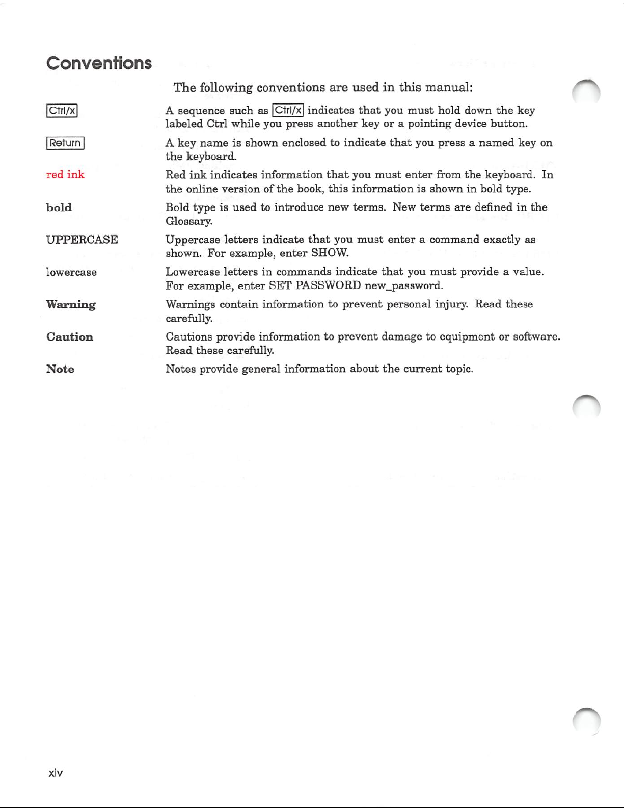
Conventions
[ctFi/^
IReturn |
red
ink
bold
UPPERCASE
lowercase
Warning
Caution
Note
xlv
The
following
conventions
are
used
in
this
manual:
A sequence
such
as |Ctrl/x|
indicates
that
you
must
hold
down
the
key
labeled
Ctrl
while
you
press
another
keyora
pointing
device
button.
A
key
nameisshown
enclosedtoindicate
that
you
pressanamed
key
on
the
keyboard.
Red
ink
indicates
information
that
you
must
enter
from
the
keyboard.
In
the
online
versionofthe
book,
this
informationisshowninbold
type.
Bold
typeisusedtointroduce
new
terms.
New
terms
are
definedinthe
Glossary.
Uppercase
letters
indicate
that
you
must
enteracommand
exactly
as
shown.
For
example,
enter
SHOW.
Lowercase
letters
in
commands
indicate
that
you
must
provideavalue.
For
example,
enter
SET
PASSWORD
new.password.
Warnings
contain
informationtoprevent
personal
injuay.
Read
these
carefully.
Cautions
provide
informationtoprevent
damagetoequipment
or software.
Read
these
carefully.
Notes
provide
general
information
about
the
current
topic.
Page 15

Margin
Icon
Definitions
o
<$-
Throughout
this
manual,
symbolsoricons
in
the
margin
identify
important
switches,
buttons,
connectors,
or
procedures.
These
icons
are
briefly
described
here.
Figure
2-3
shows
the
locations
for
many
of
the
ports
and
switches.
Icons
That
Signal
Procedures
Certain
icons
act
as
reminders
about
important
procedures
that
are
being
described
in
the
nearby
text.
This
icon
signals
that
you
turn
to
another
guide
(for
instance,
the
monitor
guide)
for
more
complete
instructions
on a
certain
procedure.
Tlien
you
return
to
the
procedures
in
this
manu£d.
This
representation
of
an
on/off
switch
shows
the
off
(0) position.
This
icon
signals
that
you
should
turn
off
oneormore
devices,
as
described
in
the
nearby
text.
The
on/off
switchisshown
in
the
on ( I ) position.
This
icon
signals
that
you
shovdd
turn
on
one
or
more
devices,
as
described
in
the
nearby
text.
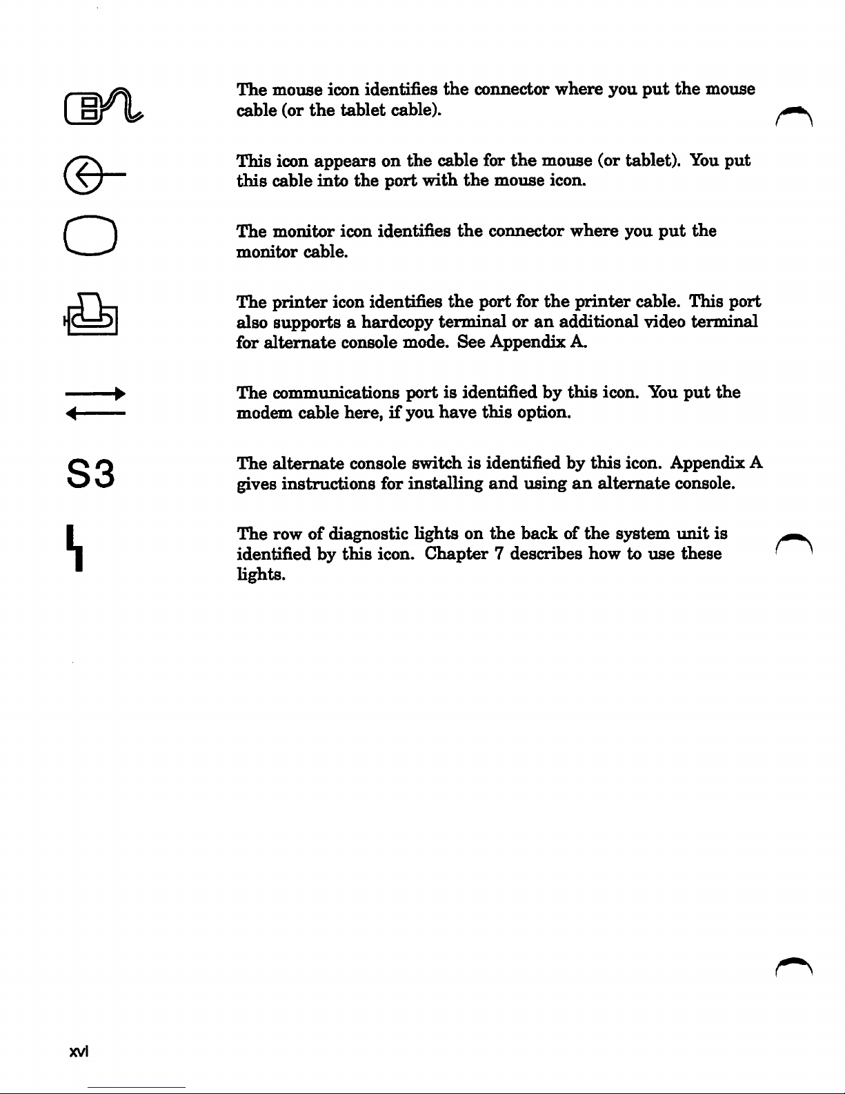
Icons
for
Ports,
Connectors,
and
Buttons
This
section
describes
the
icons
that
appear
on
the
bezel
for
the
backofthe
system
unit.
The
icon for a
port
or
connector
appears
in
the
margin
to
signal
that
you
connectacabletothat
port
or
connector.
The
icon
forabutton
appears
to
signal
that
you
press
that
button.
See
Figure
2-3
for
icon
locations
on
the
bezel.
The
SCSI
iconinthe
margin
signals
tiiat
you
attachacable
or
terminator
to
the
SCSI
port.
The
icon
for
Ethernet
signalsaprocedure
with
oneofthe
Ethernet
connectors
or
the
network
select
button.
The
halt
icon
signals
that
you
press
the
halt
button
to
put
the
system
into
console
mode.
The
keyboard
icon
identifies
the
connector
where
you
put
the
keyboard
cable.
XV
Page 16
[
©-
o
S3
^
(j^
The
mouse
cable
This
this
The
monitor
The
also
for
The
modem
The
gives
(or
icon
cable
monitor
printer
supportsahardcopy
alternate
communications
alternate
instructions
icon
the
tablet
appears
into
icon
cable.
icon identifies
console
cable
here,ifyou
identifies
cable).
on
the
port
identifies
console
for
the
connector
the
cable for
with
the
the
the
terminal
mode.
portisidentified
switchisidentified
installing
See
have
the
mouse
connector
port for
or
Appendix
this
option.
and
using
where
mouse
icon.
where
the
printer
an
additional
A.
by
this
by
an
you
(or
tablet). You
you
cable. This
icon. You
this
icon.
alternate
putthe
put
the
video
terminal
put
Appendix
console.
mouse
put
port
the
A
h
The
rowofdiagnostic
identified
lights.
bythis
icon.
lights
on
the
backofthe
Chapter7describes
how
system
touse
imit
these
is
' ^
xvl
Page 17

1
Your
VAXstation
3100
System
The
VAXstation
3100
Model
48isa
desktop
server/workstation
that
provides
the
full VMS or ULTRIX operating systems and
applications to diskless members of a work group. The VAXstation
3100
Model
48
also
functions
asaworkstation
for
the
owner/local
system manager. Figure
1-1
shows the VAXstation3100 Model 48
system.
Figure 1-1 VAXstation 3100 Model 48 System
MLO-002345
Your VAXstatton
3100
System
1-1
Page 18
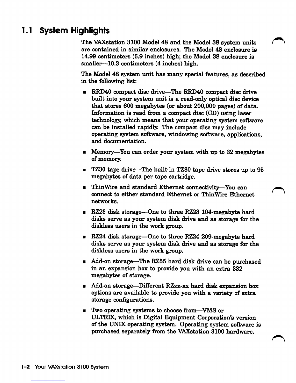
1.1
System
Highlights
The
Y&Xstation
3100
Model 48
and
the
Model
38
system
tmits
A
are
contained
in
similar
enclosures.
The
Model
48
enclosure
is
14.99
centimeters
(5.9
inches)
high;
the
Model 38
enclosure
is
smaller—10.3
centimeters
(4
inches)
high.
The
Model 48
system
unit
has
many
special
features,
as
described
in
the
following
list:
• RRD40
compact
disc drive—^The RRD40
compact
disc
drive
built
into
your
s3rstem
unitisa
read-only
optical disc device
that
stores
600 megabytes (or
about
200,000 pages) of
data.
Information is
read
from a compact disc (CD)
using
laser
technology, which
means
that
your
operating
system
software
can
be
installed
rapidly.
The
compact
disc
may
include
operating
system
software, windowing software, applications,
and
documentation.
• Memory—You
can
order
your
system
with
up
to 32 megabytes
of
memory.
• TZ30
tape
drive—^The built-in TZ30
tape
drive stores up to 95
megabytesofdata
per
tape
cartridge.
• ThinWire
and
standard
Ethernet
connectivity—You
can
connect
to
either
standard
Ethernet
or
ThinWire
Ethernet
networks.
• RZ23
disk
storage—One to
three
RZ23 104-megab3rte
hard
disks
serveasyour
system
disk
drive
and
as
storage for
the
diskless
users
in
the
work
group.
• RZ24
disk
storage—One to
three
RZ24 209-megabyte
hard
disks serveasyour
system
disk
drive
and
as
storage for
the
diskless
users
in
the
work
group.
• Add-on storage—^The RZ55
hard
disk drive can be purchased
in
an
expansion
box
to
provide
you
with
an
extra
332
megab3rtesofstorage.
• Add-on storage—^Different RZxx-xx
hard
disk
expansion box
options
are
available
to provide
you
withavariety
of
^tra
storage
configurations.
• Two
operating
systems
to choose from—VMS or
ULTRIX,
which
is Digital
Equipment
Corporation's
version
of
the
UNIX
operating
s3rstem.
Operating
system
software
is
purchased
separately
from
the
VAXstation
3100
hardware.
1-2
Your VAXstation
3100
System
Page 19

• Windowing software—DECwindows software
and,
optionally,
VAX
Windowing
Software
(VWS/UIS), give
youavisual
way
to
organize
your
work
in
windows. You
can
run
several
different
applications
simultaneously
and
switch
between
them.
You
can
use
graphic
symbols
instead
of
command
lines
to do
your
work.
•
SCSI
connectivity—Small
Computer
System
Interface
(SCSI)
is
an
industry
standard
for
connecting
mass
storage
devices.
•
For
customers
requiring
additional
security
in
their
VAX
console,
you
can
secure
your
S3^teminthe
console
mode
using
the
password
security
feature.
See
Section
7.11 for
more
information
on
this
feature.
1.2
The
VAXstation
3100
Family
The
VAXstation
3100
systems
can
be
used
in
several
configurations, from a VAXstation 3100 Model 38 diskless
workstation
used
asasatellite
inawork
group,
to a
Model
38
standalone
workstation
with
hard
disks,
toaVAXstation
3100
Model
48
used
as
the
server
for
one
or
more
Model
38
workstations.
Your Model
48
system
can
be
used
asastandalone
workstation,
oritcan
be
the
server
to
members
ofawork
group.
It
can
be
a
networked
serverifthat
work
group is connected to a
larger
network.
The
Model
38
diskless
satellite
workstation
is
the
basic,
introductory
system.
It
provides
the
optionofworking
in
a
small
work
group
or
connecting
to a
network.
Your VAXstation
3100
System
1-3
Page 20
2
Installing
After helping you check
right
up
The
running,
location for your system, this chapter shows you how to
your
system, including:
• Ck}nnecting
•
Connecting
•
Attaching
networking
•
Connecting
•
Connecting
•
Starting
chapter
including:
the
the
Ethernet
or
the
the
your
sjrstem
then
keyboard
mouse
diagnostic
monitor
power
guides you to getting your system up
System
that
you have all your equipment,
terminators
tests
cords
to
prepare
Hardware
for
either
and
and
the
set
•
•
•
What
What
modem,
Where
software
to
doifyou
to doifyou
or
printer
to
learn
about
are
are
planning
planning
installing
to connect to a
to
add
an
expansion
your
Installing System
operating
network
box,
sjrstem
Hardware
2-1
Page 21
2.1
Choosing
the
Right
Location
Use
the
following
checklist
to
ensure
that
your
VAXstation
3100
Model 48 operatesatits
best:
•
Keep
the
temperature
between
15.5®
and
32®C
(60°
and
90°F).
•
Keep
the
relative
humidity
between
40%
and
80%.
Store
tape
cartridges
at
this
himiidity.
•
Keep
the
air
well
circulated
to
prevent
excess
heat
and
dust
from
accumulating.
•
Keep
yom*
equipment
away
from
heaters,
photocopiers,
direct
simlight,
and
abrasive
particles.
•
Selectasurface
that
is
large
enough
to
holdamonitor,
a
system
unit,
andakeyboard
and
mouse.
Your
desk
or
work
tableisa good choice.
Itisimportant
that
your
system
unit
be positionedatleast
three
feet
away
from
other
operating
equipment.
• Place
the
monitorsothat
the
top
Hne of
the
monitor
display
is
at
eye
level.
Choose a
place
where
bright
light
will
not
reflect off
the
monitor,toeliminate
screen
glare.
Keep
the
area
clean.
Do
not
place
food
or
liquid
on
or
near
your
equipment,
and
do
not
place
your
system
unit
directly
on
the
floor.
Dust
and
dirt
damage
system
components.
Keep
air
vents
clear
on
each
sideofthe
system
unit
for
proper
ventilation.
Do
not
place
the
system
unit
on
its
side. Blocking
the
air
vents
can
cause
the
system
imit
to
overheat.
Connect
your
system
to
an
isolated
groxmded circuit. Do
not
exceed
the
voltage
requirement
of
the
circuit.
Let
equipment
warm
to
room
temperature
before
you
turn
it
on.
This
avoids
the
possibilityofdamaging
equipment
that
has
been
movedinfrom
the
cold.
Let
tape
cartridges
stabilize
for
24
hours.
Finally,
carefully
read
and
follow
all
installation
instructions
before
you
turn
on
the
power.
2-2
Installing
System
Hardware
Page 22
2.2
Unpacking
Monitor
System
Unit
RRD40
Test
Disc
and
Empty
CD
Caddy
Blanl^
Tape
Cartridge
Manuals
Monitor
Cable
(Color
Shown}
Keyboard
Mouse
Power
Cords
Ethernet
Loopback
Connector
Screwdriver
Two
Terminators
and
One
T-Connector
Figure
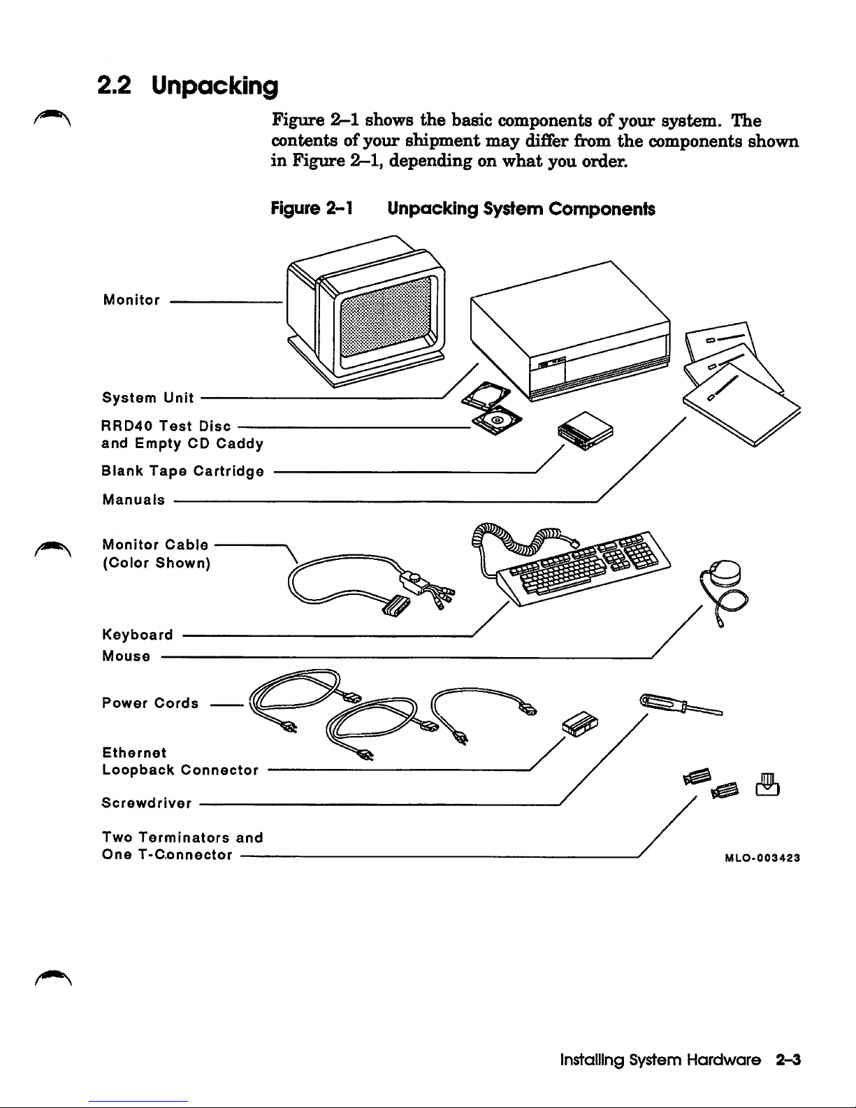
2-1
shows
the
basic
componentsofyour
system.
The
contents of
your
shipment
may
differ from
the
components shown
in
Figure
2-1,
depending
on
what
you
order.
Figure 2-1
Unpacking
System
Components
MLO-003423
Installing
System
Hardware
2-^
Page 23
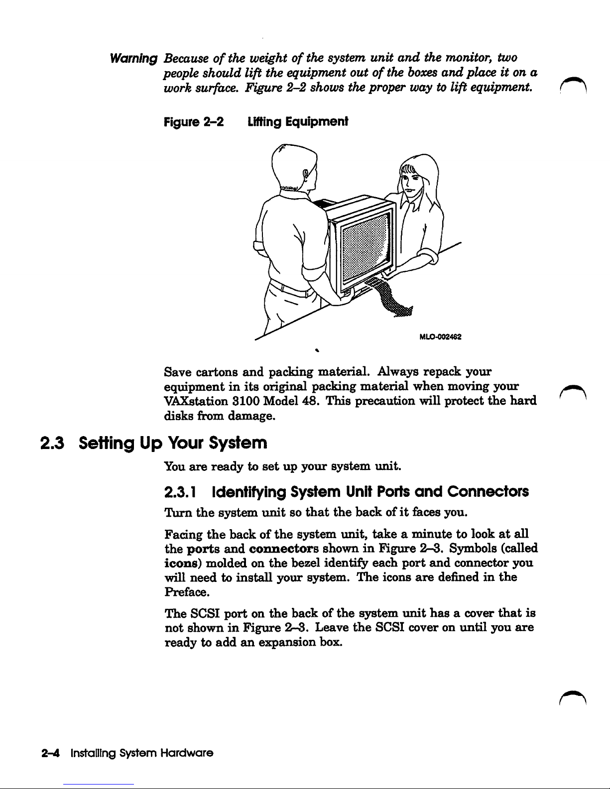
Warning Because
of
the weightofthe system unit
and
the monitor, two
people should lift the equipment
outofthe
hoooes
and
place it on a
work surface.
Figure
2-2
shows the
proper
way to lift equipment.
Figure
2-2
Lifting
Equipment
MLO-002462
Save
cartons
and
packing
material.
Alwajrs
repack
your
equipmentinits
original packing
material
when
moving your
VAXstation
3100
Model
48.
This
precaution
will
protect
the
hard
disks
&om
damage.
2.3
Setting
Up Your
System
You
are
ready
to
set
up
your
system
unit.
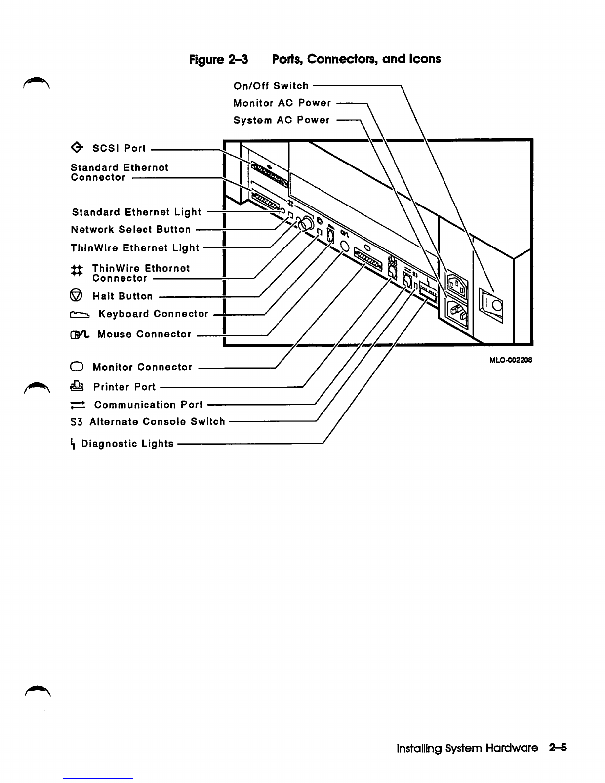
2.3.1 Identifying
System
Unit Ports
and
Connectors
Turn
the
system
unit
so
that
the
backofit
&ces
you.
Facing
the
backofthe
sjrstem luiit,
takeaminute
to lookatall
the
ports
and
connectors
showninFigure
2-3.
Symbols (called
icons)
molded
on
the
bezel
identify
each
port
and
connector
you
will
needtoinstall
your
system.
The
icons
are
definedinthe
Preface.
The
SCSI
port
on
the
backofthe
system
unit
has
a cover
that
is
not
showninFigure
2-3.
Leave
the
SCSI
cover on
until
you
are
ready
to
add
an
expansion
box.
2-A Installing
System
Hardware
Page 24
Figure
2-3
Ports,
Connectors,
and
Icons
0-
SCSI Port
Standard
Connector
Standard
Network
ThinWire
Ethernet
Ethernet
Select
Ethernet
^ ThinWire
Connector
@ Halt
r~--v
GKt
O
Button
Keyboard
Mouse
Monitor
Button
Light
Ethernet
-
Connector
Connector
Connector
Light
On/Off
Monitor
System
Switch
AC
AC
Power
Power
MLO-002208
Printer
7^
Communication
S3
Alternate
Diagnostic
Port
Console
Lights
Port
Switch
Installing System
Hardware
2-5
Page 25
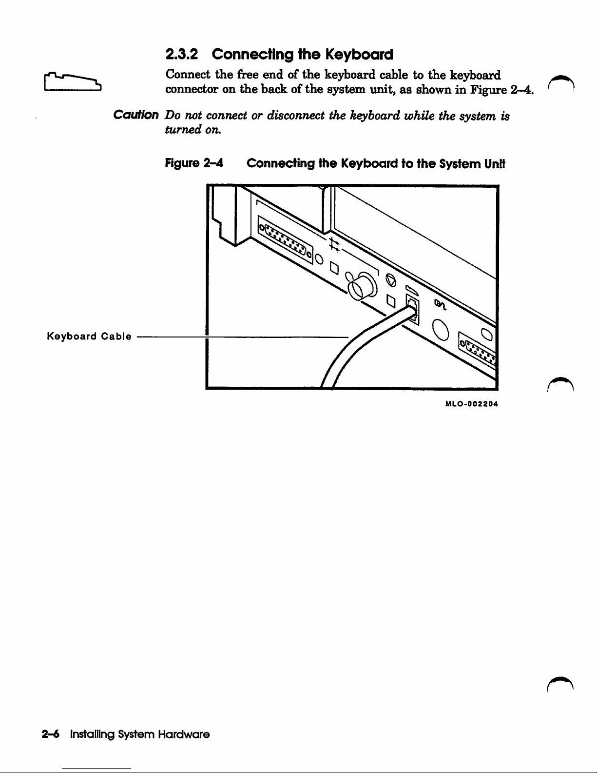
2.3.2
Connecting
the
Keyboard
Connect
the
free end of
the
keyboard cable to
the
keyboard
connector on
the
back of
the
system unit, as shown
in
Figure
2-4.
' '
CauNon Do not connect or disconnect the keyboard while the system is
turned
on.
Figure
2-4
Connecting
the
Keyboard
to
ttie
System
Unit
Keyboard
Cable
MLO-002204
2-6
Installing
System
Hardware
Page 26
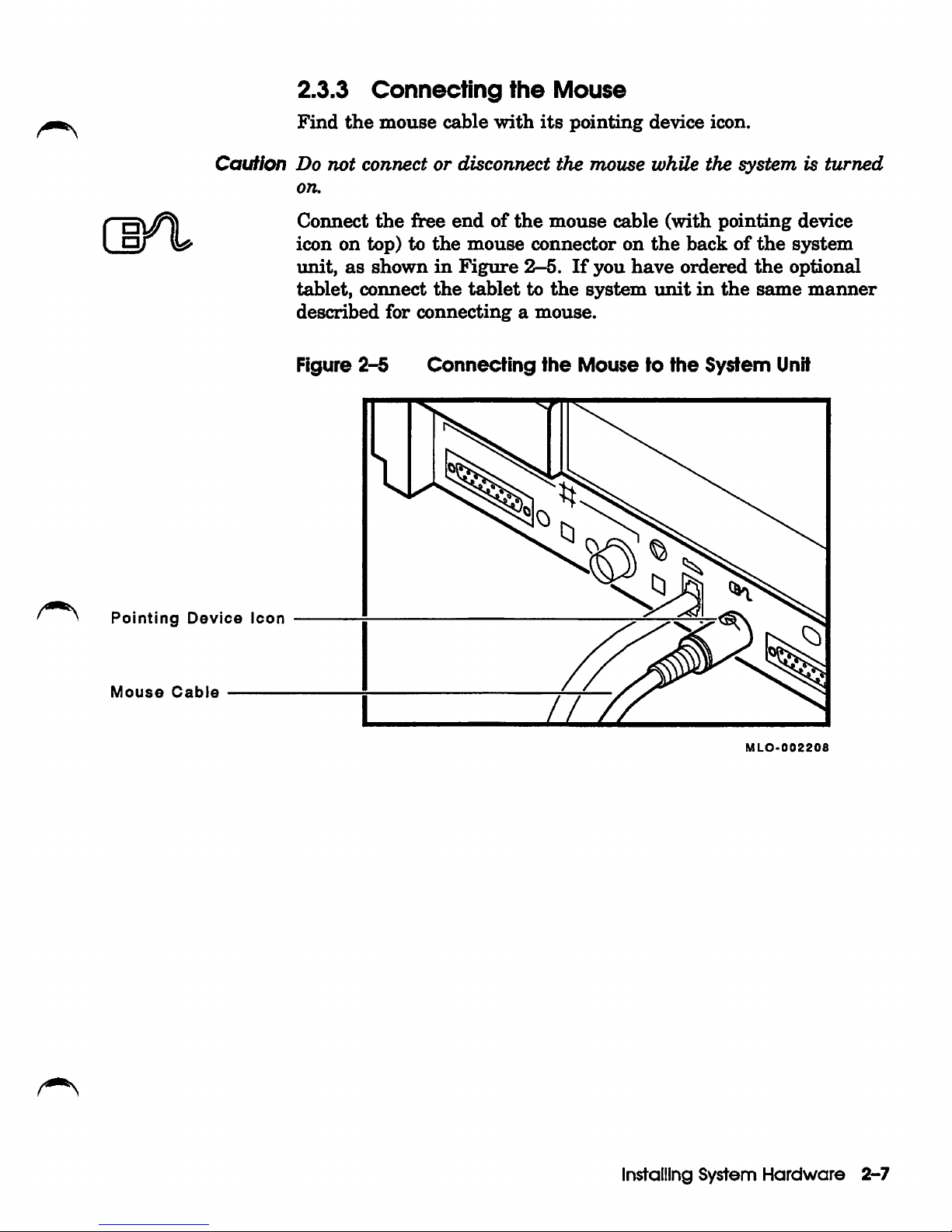
2.3.3
Connecting
the
Mouse
Find
the
mouse
cable
with
its
pointing
device icon.
Caution
Do
not
connectordisconnect
the
mouse
whUe
the
systemisturned
on.
Connect
the
free
endofthe
mouse
cable
(with
pointing
device
icon on
top)tothe
mouse
connector
on
the
backofthe
system
unit,
as
shown
in
Figure
2-5.
If
you
have
ordered
the
optional
tablet,
connect
the
tablet
to
the
system
unit
in
the
same
manner
described
for
connectingamouse.
Figure
2-5
Connecting
the
Mouse
to
the
System
Unit
Pointing
Device
Icon
Mouse
Cable
MLO-002208
Installing
System
Hardware
2-7
Page 27
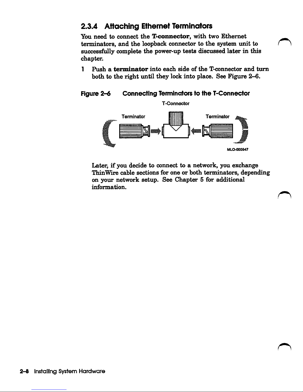
2.3.4
Attaching
Ethernet
Terminators
You
need
to
connect
the
T-coimector,
with
two
Ethernet
terminators,
and
the
loopback connector to
the
system
imit
to
successfully complete
the
power-up
tests
discussed
later
in
this
chapter.
1
Push
a
terminator
into
each
side
of
the
T-connector
and
turn
bothtothe
right
until
they
lock
into
place.
See
Figure
2-6.
Figure
2-6
Connecting
Terminators to
ttie
T-Connector
T-Connector
Terminator
Terminator
MLO-000947
Later,ifyou
decide to
connect
to a
network,
you
exchange
ThinWire
cable
sections
for
oneorboth
terminators,
depending
on
your
network
setup.
See
Chapt^
5
for
additional
information.
2-8
Installing
System
Hardware
Page 28
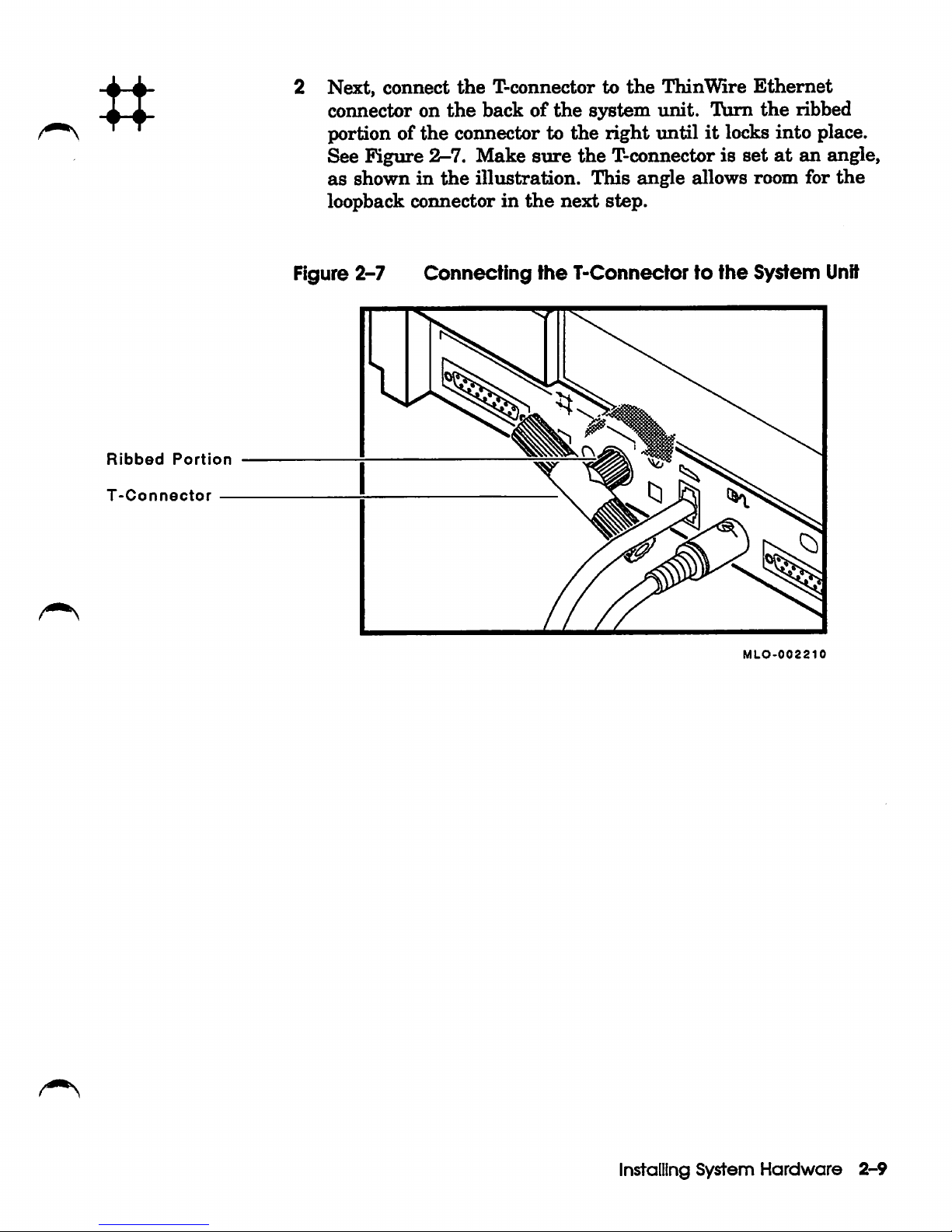
n
Next, connect
connector on
portion of
See Figure
as
shown
loopback
the
2-7.
in
connectorinthe
the
T-connector to
the
backofthe
connector to
Make
the
illustration.
sure
the
the
next
the
ThinWire
system
right
unit.
untilitlocks into place.
T-connector is
This
angle
step.
Turn
allows
Ethernet
the
set
at
room
ribbed
an angle,
for
the
Ribbed
T-Connector
Portion
Figure 2-7
Connecting
the
T-Connectortottie System
Unit
MLO-002210
Installing
System
Hardware
2-9
Page 29

Ethernet
Loopback
Connector
Connect
the
loopback
connectortothe
standard
Ethernet
connector on
the
back
of
the
system
unit,
as
shown
in
Figure
2-8.
Later,
when
the
system
has
been
turned
on,
the
green
light
on
the
connector
will come on.
Figure
2-8
Connecting
the
Loopixicic
Connector
to
ttie
System
Unit
MLO-002212
2-10
Installing
System
Hardware
Page 30
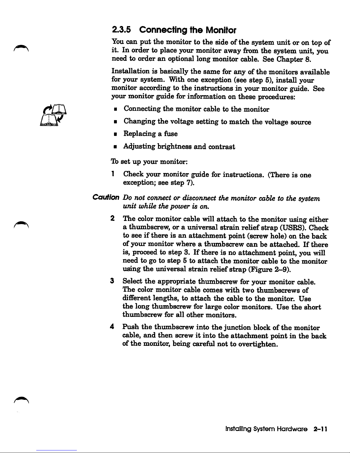
2.3.5
Connecting
the
Monitor
You
can
put
the monitor to the side of the system unit or on top of
it. In order to place your monitor away from the system imit, you
need to order an optional long monitor cable. See Chapter 8.
Installation is basically
the
same for
anyofthe
monitors available
for your system. With one exception (see step 5), install your
monitor according to the instructions in your monitor guide. See
yoiu*
monitor guide for information on
these
procedures:
•
Connecting
the
monitor
cable to
the
monitor
• Changing
the
voltage setting to match the voltage source
•
Replacingafuse
•
A^justmg
brightness
and
contrast
lb
set
up
your
monitor:
1 Check
your
monitor
guide for
instructions.
(Thereisone
exception;
see
step
7).
Caution Do not connector disconnect the monitor cable to the system
unit
while
the
power
is on.
2 The colormonitor cable will attach to the monitor using either
a thumbscrew, or a universal strain relief strap (USRS). Check
to
seeifthereisan
attachment
point (screw hole) on
the
back
of
your
monitor
whereathumbscrew
can
be
attached.
If
there
is, proceed to step 3.Ifthere is no attachment point, you will
need
to go to
step
5 to
attach
the
monitor
cabletothe
monitor
using
the
imiversal
strain
relief
strap
(Figure
2-9).
3 Select
the
appropriate thumbscrew for your monitor cable.
The
color
monitor
cable
comes
with
two
thumbscrews
of
different
lengths,
to
attach
the
cabletothe
monitor.
Use
the
long
thumbscrew
for
large
color monitors.
Use
the
short
thumbscrew
for
all
other
monitors.
4
Push
the
thumbscrew into
the
junction block of
the
monitor
cable,
and
then
screwitinto
the
attachment point in the badk
of
the
monitor, being careful not to overtighten.
Installing
System
Hardware
2-11
Page 31

Top
USRS
Bottom
•
Attach
the
universal
strain
relief
strap
to
the
color
monitor
cable by following
these
steps:
•
Insert
the
three
BNC
connectors
and
cable
junction
blockofthe
monitor
cable
through
the
center
slotofthe
universal
strain
relief
strap,
making
sure
the
strap
is
under
the
cable
junction
block.
Note
The
bottom
sideofthe
cable
junction
block
has
the
smaller
of
the two screw holes,
and
is dimpled. The universal
strain
relief
strap
should
lie
against
this
sideofthe cable
junction
block.
•
Pull
the
monitor
cable
into
the
slotted
hole
at
the
bottom
endofthe
universal
strain
reUef
strap
and
bring
the
strap
flush
with
the
cable
junction
box.
• Align
the
center BNC connector (green)
with
the
two
key
slotsofthe
closed
hole
at
the
top
end
of
the
universal
strain
relief
strap,
and
snap
the
BNC
connector
into
the
hole.
• Follow
the
instructions
in
your
monitor
guidetoattach
the
BNC
connectors
to
the
back
of
the
monitor.
Figure
2-9
shows
the
monitor
cable
attached
to
the
back
ofamonitor
using
the
universal
strain
relief
strap.
Figure
2-9
Connecting
the
Monitor
Cable
to
ttie Monitor
Using
ttie
Universal Strain Relief
Strap
BNC
Connectors
USRS
Cable
Junction
Block
MLO-004S80
2-12
Installing
System
Hardware
Page 32

o
Thumbscrews
6 Follow
the
directionsinthe
monitor
guide
to connect
the
monitor
cable
to
the
monitor.
7 Do
not
connect
the
keyboard
and
mouse to
the
monitor
cable.
(You
have
already
connected
themtothe
system
unit.)
8
Connect
the
free
end
of
the
monitor
cable
to
the
back
of
the
system
unit,
as
showninFigure
2-10.
Note
To
order
the optional longer monitor cable, see
Chapter
8.
Figure 2-10 Connecting
the
Monitor
Cable
to ttie System
Unit
9
MLO-002214
9 Tighten the thumbscrews on the monitor connector by turning
them
to
the
right.
Installing System
Hardware
2-13
Page 33

Go
2.3.6
Connecting
the
Power
Cords
The
power cord is
an
electrical ground for
your
system.
lb
connect
your
system to a power source, perform
the
foUovdng steps:
1
Make
sure
that
the
monitor
and
the
system
unit
on/o£f
switches
are
off
(0).
cautiwi
While the system
unit
automatically adjusts itselfto the correct
voltage, your monitor may
not
Refer to
your
monitorguide
when checking the monitor voltage
rating.
2
Ensure
that
your monitor's voltage requirements
match
the
voltage of the AC power outlet you
plan
to plug
the
monitor
into
before proceeding. Monitors
require
either
110 VAC or
220
VAC.
3 Connect one end of the short power cord to the monitor. Plug
the
otherofthe
power cord into
the
system unit's AC power
outlet,
as
showninFigure
2-11.
Figure 2-11
Connecting
the
Monitor
Power
Cord
Monitor
Power
Cord
MLO-002219
2-14
Installing
System
Hardware
Page 34

System
Power
Cord
Plug
one
end
of
the
long
power cord
into
the
AC power
connector
on
the
backofthe
system
iinit.
Plug
the
other
end
intoagrounded
electrical
wall
outlet.
See
Figure
2-12.
Figure
2-12
Connecting
the
System
Power
Cord
MLO-002220
Installing
System
Hardware
2-15
Page 35

2.4
Connecting
Optional
or
Expansion
Hardware
If
optional equipment is
induded
in
your order,
turn
to
the
following chapters for instructions on connecting
the
equipment to
your
system:
•
lb
connect
expansion
boxes,
see
Chapter
4.
• To
connectaprinter,
see
Chapter
8.
• Tb
connectamodem,
see
Chapter
8.
• Tb
connectatablet,
see
Section
2.3.3.
2.5
inserting
Media
Turn
the
system
unit
so
that
the
frontofit
faces you. Tb open
the
frontofthe
Model
48,
push
and
then
release
the
door
where
the
arrow
is pointinginFigure
2-13.
The
internal
RRD40 compact
disc
drive
and
TZ30
tape
drive
are
visible.
Figure
2-13
Opening
tlie
Front of
the
Model
48
System
Unit
RRD40
Compact
Disc
Drive
TZ30
Tape
Drive
MLO-002238
Insert
tiie
RRD40
test
disc,
included
in
your
initial
shipment,
in
the
disk
drive.
See
Section
3.2
for
instructions
on
how
to
correctly
insert
a compact disc. C ^
2-16
Installing
System
Hardware
Page 36

Insert
the
blank
tape
cartridge,
includedinyour
initial
shipment,
in
the
TZ30
tape
drive.
See
Chapter
3 for
instructions
on
how
to
correctly
insert
and
remove a
tape
in
the
TZ30
tape
cartridge.
2.6 Starting Your
System
3
Turn
your
s3rstem
components
on ( I ),inthe
order
giveninthe
following
list.
1
Turn
expansion
boxes
on
(I)in
the
following
order:
• RZ55
hard
disk
expansion
box
•
Other
hard
disk
expansion
boxes
•
TK50Z-GA
tape
expansion
box
•
RRD40
compact
disc
expansion
box
2
Turn
printers
and
modems
on ( I ),ifyou
have
this
equipment.
3
Turn
your
monitor
on(I).
Leave
the
monitor
on
so
that
it
turns
on
and
off
with
the
system
unit.
4
Turn
the
system
imit
on
( I ).
It
takes
approximately
90
seconds
for
the
first
line
of
the
power-up
display
to
appear
on
the
screen.
The
green
Hght
on
the
firont
of
the
monitor
should
come
on.
Thisisa good
time
to
adjust
the
brightness
and
contrastofyour
monitor. Your
screen
looks
blankifthe
brightness
and
contrast
are
turned
down
too low. Follow
the
directionsinyour
monitor
guide
to
set
the
brightness
and
contrast.
2.6.1
Checking
the
Power-Up
Display
When
you
turn
the
system
imit
on, a
power-up
display
appears
on
the
monitor
screen.
If
you
seeadisplay
similartothe
following
example,
your
system
has
passed
all
power^up
tests
and
the
keyboard
language
has
been
set:
KA42-B
F...E..
VI.2
.D...C.
? E
? E
OK
»>
0040
0050
0000.0005
0000.0005
Installing
System
Hardware
2-17
Page 37

You
may
possibly
see
a display
similartothe
following:
KA42-B
VI.2
? E
0040
0000.0005
? D
0050
0000.0005
VMS/VMB
DLTRIX
ADDR
DEVTYP
NUMBYTES
RM/FX
WP
DEVNAM
ESAO
SEO
08-00-2B-
•07-E3-83
DKA300
RZ3
A/3/0/00
DISK
104
MB
FX
RZ23
MKA500
TZ5
A/5/0/00
TAPE
RM
WP
.
..HostID
A/6
INITR
DKB200
RZIO
B/2/0/00
DISK
104
MB
FX
RZ23
DKB300
RZll
B/3/0/00
DISK
104
MB
FX
RZ23
DKB400
RZ12
B/4/0/00
RODISK
205
MB
RM
WP
RRD40
...HostID
....
B/6
INITR
[ESAO]
?
>»
»>
fTo)
If
you
see
this
display,
press
|CiTl/c| to
continue;
that
is,
hold
down
the
ICtrll
key
while
you
press
the
If
you
seeadisplay
similar
to
the
first
display
in
this
section,
your
keyboard
language
has
been
set.Ifnot,
follow
the
instructionsinSection
2.7.
^
2.6.2
If
You
Have
Probiem$
If,
after
following
the
instructions
in
the
prior
section,
you
do
not
see
the
power-up
display,
turn
your
system
unit
off
(0)
and
review
each
installation
step.
Repeat
the
power-up
procedure.
If
you
still
do
not
see
the
power-up display,
consult
Chapter
6.
2-18
Installing
System
Hardware
Page 38

2.7
If
You
Need
to Set ttte Keyboard Language
When you receive your system,
the
keyboard language should be
set
for
the
keyboard
you
ordered.
However,if the following display (the keyboard language menu)
appears
after
you
press
|Ctrl/c|in Section 2.6.1, you
needtoset
the
keyboard
language.
0)
Dansk
8)
Fran^ais
(Suisse
Romande)
1)
Deutsch
9)
Italiano
2)
Deutsch
(Schweiz)
10)
Nederlands
3)
English
11)
Norsk
4)
English
(British/Irish)
12)
Portugues
5)
Espaiiol
13)
Suomi
6)
Fran^ais
14)
Svenska
7)
Frangais
(Canadien)
15)
Vlaams
3?
>»
lb
set
the
keyboard
language,
perform
the
following
steps:
1
Select a language from
the
keyboard language
menu
to match
the
typeofkeyboard
you
have.
2
If
you
want
to select the default language (English, which is
option 3),
press
the
Return
key. Otherwise,
enter
the
number
of
the
language
that
matches
the
language of your keyboard,
and
press
the
Return
key.
A different keyboard is available for each language.Ifyou do
not know
the
language variation of
the
keyboard you received,
check
the
packing
list.
The language you chose is now savedinmemory. If you need to
change the keyboard language later, Chapter 6 shows you how.
Installing
System
Hardware
2-19
Page 39

2.8
Connecting
to
o
Network
If you are connecting your system to a work group (whether or
not you
are
connecting to a larger network), read Chapter 5. You
will need to
install
your network
hardware
before you install your
operating
system
software.
2.9 Getting
Ready
to
Install
Your
Operating
System Software
Tb
install
your VMS or ULTRIX operating system software, you
need
one
of
the
following:
• TZ30
tape
drive
•
Connection
toanetwork
to
load
the
software
from
another
system
• RRD40
compact
disc
drive
•
TK50Z-GA
tape
drive
Your Model 48 system is
set
at
the
factory to
automatically
start
your operating system software from any device
that
you specify
during
the
software
installation
procedure.
Verify
that
the
default recovery (automatic boot) on your system
is
set
to 2.
Enter
the
following
command
at
the
console
prompt
(»>):
»>
SHOW
HALTIReturn
I
2
»>
See Appendix Aifyou need to change
the
default recovery to 2.
lb
install
VMS
or
ULTRIX
software
on
the
VAXstation
3100
Model 48, follow
the
installation instructions
that
were shipped
with
the
software.
During
software
installation,
the
software
is
transferred
from
the
installation
medium
(tape
cartridge
or
compact disc) to
the
hard
diskinyour VAXstation 3100 Model 48
ortoan
expansion
box.
If
your software does
not
load
properly, see
Chapter
6.
The
RRD40
test
disc
that
comes
with
the
RRD40
compact
disc
drive
can
help
you
determine
the
source of
the
problem.
If
your local
area
VAXcluster is
part
of a
larger
network, you
may
be
able
touseRemote System Manager
(^M)
software
ona
host
systemtodown-line
load
and
install
application
software.
2-20
Installing
System
Hardware
Page 40

2.10 Turning YourSystem Off
If
you need to
turn
your system off, follow the shutdown
o
instructionsinyour
operating
system
software documentation.
No/e
Whenyou use a VAXstation3100 Model 48 in a cluster, you should
not
turn
off,
halt, or restart the system without notifying work
group members. These activities affect the operation
of
the entire
work
group.
After completing the system shutdown,
turn
your equipment off
(0)inthe
following
order:
1
Expansion
boxes
2
Printer,
modem,
or
other
equipment
3
Monitor
and
system
unit
Installing System
Hardware
2-21
Page 41

3
Learning
About
Your
System
This
chapter
provides
information
about:
•
RZ23
and
RZ24
hard
disks
• RRD40
compact
disc
drive
•
Tape
cartridges
• TZ30
tape
drive
•
Mouse
3.1
Hard
Disk
Drives
A
hard
disk
stores
information
onanonremovable
disk.
You
can
have
up
to
three
hard
disksinyour
Model 48
system
imit.
The
RZ23
has
104
megabytesofstorage,
while
the
RZ24
has
209
megabytes
of
storage.
RZ23
and
RZ24
hard
disks
are
mounted
internally
in
the
S3rstem
unit.
Additional
disks
can
only
be
addedifthereisavailable
space.
Tb
determine
the
number
of
disksinyour
system,
enter
TEST
50
at
the
console
prompt,
then
press
the
Return
key.
Your
system
configurationisdisplayed
on
the
screen.
It
lists
the
storage
devices
mounted
in
your
system.
An
example
configuration
display
can
be
found
in
Section
7.3.
You
can
increase
your
system's
storage
capacity
with
the
RZ55
hard
disk
expansion
box
and
the
RZ5x-xx
series
of
hard
disk
expansion
boxes.
See
Chapter
4 to
leam
about
expansion
boxes.
Learning
About
Your
System
3-1
Page 42

3.2 Using
the
RRD40
Compact
Disc Drive
RRD40
Compact
Disc
Drive
TZ30
Tape
Drive
Turn
the
system
unit
so
that
the
jBrontofit
faces you. To open
the
frontofthe
Model 48,
push
and
then
release
the
door
where
the
arrowispointing
in
Figure
3-1.
Figure 3-1
Opening
the
Front of
the
Model 48 System
Unit
MLO-00223B
The
integral
RRD40 compact disc drive
and
TZ30
tape
drive
are
visible.
The
front
of
the
RRD40
has
an
opening
for
the
optical
disc
and
one
activity
light.
The
green
activity
light
goes on
when
you
loadacompact
discinthe
drive
and
flashes
when
the
disc is
transferring
information.
3.2.1
Loading
a
Compact
Disc
To
loadacompact
disc
into
the
disc drive,
insert
the
entire
disc
caddy
into
the
disc
opening
on
the
drive.
Do
not
remove
the
compact
disc
from
the
caddy.
To
load
a
disc:
1
Examine
the
disc
caddy.
Make
sure
that
itisnot
cracked
or
damaged
in
any
way.
Never
loadadamaged
caddy
into
a disc
drive.
3-2
Learning
About
Your
System
Page 43

Insert
the
disc caddy
as
showninFigure
3-2.
The
label on
the
disc
should
always
be
&cing
up
when
you
insert
the
disc
into
the
drive.
Make
sure
the
notches
on
the
left
side
of
the
disc
caddy
line
up
with
the
notches on
the
opening of
the
drive.
Figure
3-2
LoadingaCompact
Disc
MLO-002241
Learning
About
Your
System
3^
Page 44

Note
3
If
you
have the disc positioned label
on
the
right,
then
Proceednofurther
Section
Slide
transparent
the
Figure
3.2.3.
the
drive.
3-2.
caddy
sleeve.
Only
in
the
the
discisoriented
with
the
disc
as
far
asitwill
The
disc
transparent
loading.
and
its
side
up
but
improperlyinthe
See
Section
go
and
then
housing
sleeve
remain
comes
the notches
caddy.
3.2.4
remove
out.
the
in
See
are
^
and ' ^
4 Also
3.2.2
Before
lightisnot
driveistransferring
flashing. To
1
2
3
note
that
comes
The
the
does
caddy. Remove
is
on
green
drive
not
facing
and
activity
accepted
come on,
up
as
Removing
removingacompact
flashing.
imload
Position
arrow
Insert
Remove
sleeve.
on
the
The
the
transparent
the
sleeveispointing
sleeve
the
caddy.
green
the
stays
the
you
data.
a disc:
into
green
on.
light
the
disc
the
disc
disc
and
insert
a
Compact
disc,
If
the
light
Wait
the
The
disc
activity
light
should
sleeve
on
come on
and
caddy
may
be
checktomake
the
disc
make
is flashing,
until
as
into
drive
and
Hght
opening
should
the
front
but
sitting
into
Disc
sure
the
green
for
loading.
the
housing
of
within
the
incorrectly
sure
the
drive
that
the
activily
drive
as
far
should
go
out.
the
disk
drive
5 seconds.
activity
that
again.
the
green
compact disc
Make
opening.
asitwill
be
Hght
in
the
activity
light
sure
in
the
the
go.
If
label
stops
the
3-4
Learning
About
Your System
Page 45

Notches
Housing
Label
Disc
Transparent
Sleeve
3.2.3 Inserting
the
Compact
Disc into
the
Caddy
A compact disc is contained
inside
a protective caddy for
insertion
into
the
compact disc drive.
The
caddy consists of
three
parts:
the
disc,
the
honsing,
and
the
transparent
sleeve,
as
shown
in
Figure
3-3.
Figure
3-3
Compact
Disc
Caddy
MLO-002239
Learning
About
Your
System
3-5
Page 46

Notches
Label
lb
place a compact disc into a caddy, perform
the
following steps:
1 Hold
the
disc
with
yoiir
free
hand.
Position
the
housing
and
disc
as
showninFigure
3-4
(always work with
the
disc so
the
label is facing up,
and
the
four notches on
the
housing
are
to
the
left).
2 Position your
thumb
on
the
outer
edge of
the
disc
and
your
index finger in
the
center hole of
the
disc.
3 Slip
the
disc into the housing. The inside of
the
housing is
grooved to accept
the
disc.
Exert
inward pressure on
the
housing
to hold
the
disc
in
the
housing.
Figure
3-^
Inserting Disc in Housing
MLO-002351
Slide
the
housing
into
the
transparent
sleeve
imtilitclicks
into
place.
Turn
the
assembled
caddy
so
that
the
label
on
the
disc is
&cing up. Make
sure
that
the
notches on
the
housing
are
on
the
left.
If
the
notches
are
not
on
the
left
when
the
disc
is label side up,
then
the
disc is mounted inside
the
caddy
incorrectly. Remove
the
disc
fi:x)m
the
caddy,
turn
the
disc
over,
and
placeitin
the
caddyinthe
correct position.
3-6
Learning
About
Your
System
Page 47

Itisimportant
caddy.
thatisincorrectly
The
removeitand
that
compact
remountitin
the
disc
disc
drive
mounted.
be
cannot
If
the
the
correctly
discisincorrectly
mounted
access
data
caddy.
in
the
from a
mounted,
disc
Locking
Tabs
3.2.4
To
remove
perform
1
Hold
locking
2
Press
separating
or a
Figure
Removing
the
disc
the
following
the
caddy
tabs
down
the
sharp,
3-5
pointed
Pressing Loclcing Tabs
from
on
either
on
both
housing
the
the
steps:
so
thatitis
of
instrument.
Compact
caddy
facing
sideofthe
the
locking
fr^m
the
Disc from
for
cleaning
label
disc
tabs
sleeve.
See
Figure
or
side
housing.
while
Use
3-5.
ttie
caddy
down.
sUghtly
your
Caddy
repair,
Locate
fingernails
the
When
outtoabout
Hold
the
from
both
the
disc
housing
the
housing.
tabs
the
housing
so
have
midpoint
the
disc
Place
been
on
will
the
disengaged,
of
the
disc.
each
side.
not
fall
sleeve
Learning
Exert
out.
aside.
pull
the
inward
Remove
About
disc
Your
MLO-002240
housing
pressure
the
sleeve
System
on
3-7
Page 48

5 Hold
the
disc
with
your
free
hand
as
showninFigiire
3-4.
Position
your
thumb
on
the
outer
edgeofthe
disc
and
your
index finger
in
the
center hole of
the
disc. Release pressure
from
the
housing
and
remove
the
disc.
3.2.5
Caring
for
Compact
Discs
Protectadisc
from
dust,
ink,
fingerprints,
or
other
contaminants
wheneveritis
hot
in
the
caddy.
• Always
handle
a disc by
the
outer
and
inner
edges.
•
Never
touch
the
data
areaofthe
disc
(the
area
covered by
the
silk-screened
label).
When
loading a disc,
gently
insert
the
disc caddy
into
the
compact
disc
drive.
To
unload
a disc,
simply
insert
the
transparent
sleeve
into
the
compact
disc
drive.
Compact
discs
can
be
cleaned
with
a dry,
lint-free
cloth. Tb
dean
a disc,
wipe
from
the
centerofthe
disctothe
edges.
Use
small
circular
strokes.
Do
not
useacontinuous
circular
stroke
around
the
disc.
3.3
Using
Tape Cartridges ^
This
section
shows
you
how
to
•
Labelatape
cartridge
•
Writetoand
protect
tape
cartridges
•
Handle
and
store
tape
cartridges
•
Use
the
TZ30
tape
drive
•
Insert
and
removeatape
cartridge
•
Understand
TZ30
Hghts
3.3.1
Labeling
a
Tape
Cartridge
The
TK50Z-GA
and
TZ30
tape
drives
both
use
TK50-K
95-
megabsrte (CompacTape)or*nC52-K 296-megabyte
(Compac^pe
II)
tape
cartridges.
Always
label
tape
cartridges.
A
slot
for
the
labelisprovided
on
the
firontofthe
cartridge,
as
shown
in
Figure
3-6.
In
this
slot,
the
labelisvisible
when
the
cartridge
is
in
the
drive.
Labels
or
markings
on
any
other
part
of
the
cartridge
can
interfere
3-8
Learning
About
Your
System
Page 49

with
proper
operation
of
the
drive. Do
not
write
directly
on
the
cartridge
with
pen,
pencil,orother
marking
medium.
Figure
3-6
LabelingaTape
Cartridge
Label
Slot
3.3.2 Writing
to
and
Protecting
Tape
Cartridges
Write
protecting
a
tape
prevents
accidental
erasure
of
information.
The
VAXstation
3100
Model
48
can
read
information
on
the
tape
regardless
of
the
position
of
the
write-protect
switch.
However,
the
VAXstation
3100
Model
48
cannot
write
data
to
a
write-protected
tape.
Learning
About
Your
System
3-9
Page 50

3.3.2.1 Write
ProtectingaTape
When
you
useatapetoinstall
software,
set
the
write-protect switch on
the
frontofthe
cartridge
to
the
write-protect
position.
Tb
write
protectatape,
sUde
the
write-protect
switch
left
toward
the
label
untilitlocksinplace
(Figure
3-7).
An
orange
rectangle
appears
when
the
write-protect switch locks
in
the
write-protect
position.
Figure
3-7
Write
ProtectingaTape
^
mup-
Not
Write-
Protected
WriteProtected
If
you
move
the
write-protect
switchtothe
right
during
operation,
the
software
does
not
recognize
that
the
tape
is
no
longer
write-
protected. To
write-enable
the
tape, unload
the
tape
Section 3.4.2,
3-10
Learning
About
Your
System
Page 51

slide
the
write-protect switch to
the
right,
and
begin
tape
loading
procedures again. The software will now recognize the cartridge
as
write
enabled.
Similarly,ifyou move
the
write-protect switch to
the
left during
operation,
the
tapeisnot
write-protected until
the
current
command
completes.
3.3.2.2 Witting to a
Tape
When you use a
tape
to make a
backup copy or to write out data, set the write-protect switch to
enable
writing
to
the
tape.
To enable writing, slide the switch to
the
right,
away
from
the
label,
imtil
the
switch
locksinplace.
3.3.3
Handling
and
Storing
Tope
Cartridges
Take
the
following precautions
when
handling
and
storing
tape
cartridges:
•
Never
touch
the
exposed
surface
of
the
tape.
• Avoid
dropping
the
tape
cartridge.
The
impact
can
cause
damage.
• Allow new
tape
cartridges to come to room
temperature
before
using
them.
•
Write
on
the
identification
label
before slidingitinto
the
slot
on
the
tape cartridge. Do
not
put
the
label anywhere else on
the
cartridge.
•
Store
tape
cartridges
away
from
dust
in
their
plastic
covers.
• Keep
tape
cartridges out of direct sunlight,
and
away ftt)m
heaters
and
other
heat
sources.
Store
tape
cartridges
at
an
even temperature between
10®C
and
40°C (50°F
and
104°F).
Store
cartridges
where
the
relative
humidityisbetween
40%
and
80%.
• Keep
tape
cartridges away
fit>m
magnets
and
equipment
that
generates magnetic fields, such as motors, transformers,
and
video
monitors
and
terminals.
•
Keep
tape
cartridges
away
from
X-ray
equipment.
Learning
About
Your System 3-11
Page 52

3.4
Using
the
TZ30
Tape
Drive
The
TZ30
tape
drive
holds
one
removable
magnetic
tape
cartridge.
The
tape
cartridge
stores
up
to 95
megabytes
of
data.
Use
the
tape
cartridge
to
load
software
or
data
ortomake
copies (or
backups)
of
software
or
data.
Figure
3-8
shows
the
indicator
lights
and
the
imload
button.
The
TZ30
tape
drive
can
read
data
&om
and
write
data
to a
tape
that
was
written
byaTK50Z-GA
tape
drive.
The
TZ30
tape
drive,
however,
cannot
read
&om,orwrite
data
to, a
tape
that
has
been
written
by
the
TK70
tape
drive.
Figure
3-8
TZ30
Lights
and
Controls
Write-Protect
Light
Tape-in-Use
Light
Operate-Lever
Light
Unload
Button
MLO-005087
3.4.1 Inserting a
Tape
Cartridge
Tb
leam
about
tape
cartridges,
see
Section
3.3. To
insertatape
cartridge,
follow
these
steps:
3-12
Learning
About
Your
System
Page 53

1
Make
sure
the
system
unitison
( I ).
2
Make
sure
the
tape
drive
lever
is to
the
left
in
the
unlock
position.
See
Figure
3—9.
3
Insert
the tape cartridge, as shown in Figure
3—9.
The
operate-lever
light
(green) comes on.
Figure
3-9
Inserting a
Tape
CartridgeInthe
TZ30
MLO-002243
4
With
the
cartridge
all
the
way
in,
move
the
lever
to
the
lock
position, all
the
waytothe
right.
The
green
light
goes off
and
the
yellow (tape-in-use) light blinks, indicating
that
the
tape
is
loading.
When
the
tape
is loaded
(ready
for use),
the
yellow
light
stays
on continuously.
Whenever
the
yellow
light
is on continuously
anditis
the
only
light
on,
the
tapeisready
to \ise.
When
the
tape
is
being
read,
written
to, or
rewound,
the
yellow
light
blinks.
NoteIfthe write-protect switch on the cartridge is in the write-protect
position, the
orange
write-protect
light
on
the
frontofthe tape drive
comes on
and
you
will
notheable
to write
data
to the tape.
Learning
About
Your
System
3-13
Page 54

3.4.2
lb
removeatape
1
Removing
Press
the
cartridge:
unload
a
Tape
button.
Cartridge
Caution
Wait
approximately
yellow
2
When
the
beep
(to
the
shown
A
tape
cartridge
before drive
can
result
Figure
3-10
light
the
green
sounds
left).
in
Figure
will
flash
light
twice, move
The
3—10.
must
cartridge
be
poweristurned
in
damage
to both
RemovingaTape
two
minutes
as
the
comes on,
unloaded
off.
the
for
the
tape
tape
rewinds.
the
yellow
the
lever
to
ejects. Remove
and
removed from the drive
Failure
cartridge
to remove the
and
Cartridge
to
rewind.
light
the
the
the
from
goes off,
unlock position
cartridge
drive.
the
TZ30
The
and
as
cartridge
3-14
Learning
About
Your
System
MLO-002244
Page 55

3.5
Mouse
3.4.3
Understanding
1Z30 Lights
Table
3—1isa
siunmary
of
the
possible
light
combinations.
Table
3-1
Understanding
TZ30
Lights
Ught
State
Meaning
Green
(operate-lever)
On
OKtooperate
the
cartridge
lever.
Off
Do
not
operate
cartridge
lever.
Blinking
Cartridgeorcalibration
error
detected.
See
Chapter
6.
Yellow
(tape-in-use)
Blinking
Tape is in use.^
On
Tape
is loaded
and
ready
for
use.
Orange
(write-protect)
On
Tapeiswrite
protected.
Off
Tapeiswrite
enabled.
All
three
lights
On
Power-up
diagnostic
test
in
progress.^
Blinking
Drive
fault.
See
Chapter
6.
^Intermittent fast blinking indicates
that
a write is in prc^ess. Continuous
fast
blinking indicates
thatareadisin
progress. Medium blinking iodicates
calibratioxi. Slow blinking indicates
that
the
tapeisinitializing, loading, unloading,
or rewinding. The
light
blinks slowly for 10 seconds indicating drive initialization
on
poww-up
after
the
power-up diagnostic
has
run.
^AU
three lightsstay onfora
few
seccmds
while
the
power-up
diagnostic
test is
running.Ifall
three
lights
stay
on for longer
than
a few seconds,
the
power-up
diagnostic
has
failedoran
error
occurred
duringanoperation.
3.4.4
If
You
Have
Problems
If
an
error
occurs
when
you
are
reading
or
writing
to a
tape,
all
three
lights
bHnk.Ifan
error
occurs
when
you
are
inserting
the
tape
cartridge,
the
green
light
blinks
and
the
tape
does
not
move.
In
either
event,
see
Table
6-1
for
troubleshooting
instructions.
You
can
use
the
mousetopointtoand
select
objects on
the
screen
after
instalUng
windowing
software
on
your
system.
To
learn
how
to
use
your
mouse,
see
your
windowing
documentation.
Learning
About
Your
System
3-lS
Page 56

4
Adding
and
Using
Expansion
Boxes
This
chapter
provides
information
about
installing
and
uang
compact disc,
hard
disk,
and
tape
expansion
boxes.
An
expansion
boxisan
external
box
that
connectstoyour
system
unittoprovide
additional
compact
disc,
hard
disk,
or
tape
storage.
Each
expansion
boxisshipped
with
the
appropriate
cables
and
connectors
for
connecting
more
than
one
box.
Cable
connections
and
installation
instructions
are
similar
for
all
three
expansion
boxes.
The
following
expansion
boxes
can
be
used
with
a
VAXstation
3100
system:
•
332-megabyte
RZ55
hard
disk
expansion
box
•
95-megabyte
TK50Z-GA
tape
expansion
box
•
600-megabyte
RRD40
compact
disc
expansion
box
•
Various
RZ5x-xx
storage
options
Instructions
for
the
following
tasks
are
included
in
this
chapter:
•
Connecting
oneormore
expansion
boxestoyour
ss^stem
unit
• Verifying
the
SCSI
ID
default
(factory)
switch
setting
on
the
first
expansion
box
•
Setting
the
SCSI
switches
on
a second
expansion
box
•
Adding
and
using
the
TK50Z-GA
tape
e^ansion
box
•
Testing
your
expansion
boxes
Adding
and
Using Expansion Boxes
4-1
Page 57

The
RZ55
hard
disk
and
the
TK50Z-GA
tape
drive
provide
disk
and
tape
storage
fiw
your
system.
Optionally,
the
TK50Z-GA
can
be
used
to
load
software.
•
The
RZ55
and
the
TK50Z-GA
are
enclosed
in
similar
expansion
boxes.
•
If
you
have
more
than
one
RZ55
expansion
box,
you
must
reset
the
external
SCSI
ID
switches
on
the
second
RZ55.
•
Information
on
the
RZ5x-xx
expansion
box
seriesiscovered
in
the
manual
that
ships
with
each
individual
option.
Please
refertothat
manual
for
information
on
adding
any
oneofthe
RZ5x-xx
seriesofexpansion
boxes.
The
RRD40
compact
disc
drive
isaread-only
storage
device
that
reads
data
from
removable
compact
discs.
The
RRD40
disc
driveisan
integral
device.
It
is
also
available
in
an
external
expansion box.
Chapter
3 describes
the
integral
RRD40 compact
disc
drive.
This
chapter
discusses
the
expansion
box
model.
The
RRD40 compact disc
expansion
box
can
be
used
for
many
purposes.
For
example,itcan
be
used
for
application
software
installation,
database
storage,
and
online
documentation.
•
The
RRD40
compact
disc
expansion
boxiscontained
in
a
smaller
expansion
box
than
the
RZ55
and
the
TK50Z-GA.
•
Cable
connections
and
installation
instructions
for
the
RRD40
compact
disc
expansion
box
are
similar
to
those
for
the
RZ55
and
TK50Z-GA
expansion
boxes.
•
The
RRD40
compact
disc
expansion
box
has
external
SCSI
ID
switches
that
you
must
set
for
your
configurationifyou
have
more
than
one.
• You
can
set
the
voltage selector on
the
RRD40
expansion
box
to
either
110 volts
or
220
volts,
depending
on
your
power
requirements.
4.1
Guidelines
for
Connecting
Expansion
Boxes
Use
the
following
guidelines
when
connecting
expansion
boxes:
•
Connect
no
more
than
three
expansion
boxes
to
the
Vj\Xstation
3100
SCSI
port.
Remember
the
following
SCSI
rules:
•
Seven
SCSI
IDs
are
available
for
customer
configuration.
4r>2
Adding
and
Using Expansion Boxes
Page 58

• Multiple SCSI devices
may
be
housedinone eiqpansion
box,
but
the
number
of
SCSI
devices
cannot
exceed
seven.
For
more
information
on
SCSI,
please
refer
to
the
following
documentation
kit.
Small
Computer
System
Interface:
An
Overview
and
a Developer's
Guide.
m
Each
device
must
have
its
own
unique
SCSI
ID.
Some
SCSI
devices
may
not
be
housed
in
an
e:^ansion
box.
Always
limit
the
number
of
SCSI
devices
per
SCSI
bus
to
seven
when
you
configure
your
VAXstation
3100
Model
48
system.
Use
only
the
expansion
boxes purchsised for
the
V^Xstation
3100.
Expansion
boxes
purchased
for
use
with
other
Digital
equipment
may
need
to be
upgraded
by
Digital field service.
A
system
must
have
an
integral
hard
disk
andaSCSI
controllerinordertosupport
an
expansion
box.
Always
attach
the
50-pin
SCSI
terminator
that
comes
with
your
expansion
boxtothe
unused
SCSI
connector
on
the
last
^pansion
box.
All
expansion
boxes
should
be
plugged
into
the
same
groimded
power
strip
or
electrical
source.
THim on
all
expansion
boxes before
you
turn
on
a VAXstation
3100
system
unit.
Turn
them
oninthe
following
order:
- RZ55
hard
disk
expansion
box
or
boxes
-
Other
hard
disk
expansion
boxes
-
TK50Z-GA
tape
expansion
box
- RRD40
compact
disc
expansion
boxorboxes
This
procedure
ensures
that
the
deviceineach
expansion
box
is
ready
to
be
used,
and
that
the
system
firmware
includes
the
deviceinits
configuration.
After
installing
an
expansion
box,
see
Chapter
7 for
instructions
on how to
display
your
new
system
configuration
(TEST
50),
and
howtorun
the
system
exercise
(TEST
0).
Adding
and
Using
Expansion
Boxes 4r-3
Page 59

4.2
Unpacking
an
Expansion
Box
Note
This
section
describes
the
TK50Z-GA
expansion
box,
the
RZ55
expansion
box
and
the
KRD40 compact disc drive. The newer
RZ5x-xx eoqjansion box options
have
their
own user documentation.
Please
refertoindividual
RX5x-xx
documentation
for
specific
installation
instructions.
Each
expansion
box is
shipped
from
the
factoxy
with
the
following
accessories,
as
shown
in
Kgure
4—2:
•
Eitheracable
witha68-pin
connector
at
one
end
anda50-pin
connectoratthe
other
end,
or
a cable
with
a 50-pin connector
on
each
end
anda68-pin
to
50-pin
adapter,
which
you
will
plug
into
one
endofyour
50-pin cable.
Use
this
cable
(and
the
adapter,ifnecessary) to connect
the
expansion box to
the
system
unit.
Nofe
The 68-pin connector is
shaped
differently
from
the
50-pin
connector.
See
Figure
4-2.
One
50-pinto50-pin
cable.
Use
this
cable to
connect
two
expansion
boxes
in
a chain.
One
power
cord.
One
bottom
dress
cover
(for
RZ55
or
TK50Z-GA).
See
Section
4.3.
One
50-pin
terminator,
as
showninFigure
4—1.
Use
this
to
terminate
the
last
expansion
box.
Figure 4^1 50-Pin Terminator
MLa«02346
4-4
Adding
and
Using
Expansion
Boxes
Page 60

50-Pin
to
50-Pin
Connector
Cable
Power
Cord
Terminator
68-Pin
to
50-Pin
Adapter
68-Pin
to
50-Pin
Connector
Cable
Make sure you have all the
parts
shown
in
Figure 4r-2before you
set
up
your
expansion box.
Note
that
the
RRD40 compact disc
expansion
box
differs
somewhat
from
the
RZ55
or
TK50Z-GA
expansion
box
showninthe
figure,
but
the
cables
and
terminator
are
identical.
The
bottom
dress
cover
that
comes
with
the
RZ55
and
TK50Z-GA expansion boxes is not shown in Figure
4-2.
See
Section
4.3.
In
addition,
the
TK50Z-GA expansion box comes
withablank
tape
cartridge,
and
the
RRD40 compact disc expansion box comes
with
an
empty
compact disc
caddy
and
test
disc.
Figure 4r-2
Unpacking
an
RZ55orTK50Z-GA Expansion Box
MLO-004582
Adding
and
Using Expansion Boxes
4-^
Page 61

4.3 Installing a Bottom Dress
Cover
Bottom
Dress
Cover
Rubber
Foot
The
RZ55 or TK50Z-GA expansion box comes
with
a bottom
dress
cover. Tb
install
the
bottom
dress
cover, follow
these
steps:
1 Place
the
expansion box
upside
down on a level surface.
2 Remove
the
four
rubber
feet
(optional).
3 Locate
the
bottom
dress
cover. Lane
up
the
molded
inserts
on
the
inside
of
the
bottom
dress
cover
over
the
holes
on
the
bottomofthe
eaqpansion box. Note
that
you
must
match
the
sizeofthe
inserts
with
the
sizeofthe
holes.
See
Figure
4-3.
4
Slide
the
bottom
dress
cover
untilitlocks
into
place.
Figure
4^
Installing Bottom Dress
Cover
ML(M>05080
4r-6
Adding
and
Using Expansion Boxes
Page 62

4.4
Preparing
Your
System
for
on
Expansion
Box
no)
SCSI
Cover
Lift
Locking
Tab
to
Release
lb
add
an
expansion
boxtoyour
system,
you
must
first
remove
the
SCSI
cover
and
the
terminator
fi:t)m
the
SCSI port.
1
Turn
your
system
off
(0).
2
lb
remove
the
SCSI covct,
press
your fingers on
the
locking
tab
and
lift
the
cover to
release
it,
as
showninFigure
4—4.
Figure 4r-4
Removing
the
SCSI
Cover
MLO-00222S
Adding
and
Using
Expansion
Boxes
4-7
Page 63

SCSI
Terminator
Loop
lb
remove
the
SCSI
terminator,
place
your
fingers
under
the
loop
and
pull
out.
Figure
4-5
shows
you
howtoremove
the
terminator.
Figure
4^-5
Removing
the
SCSI Terminator
MLO-002230
Save
the
terminator
and
the
cover. You
must
reattach
themifyou
disconnect
all
expansion
boxes
from
the
system
unit.
4-8
Adding
and
Using
Expansion
Boxes
Page 64

4.5
Connecting
One
Expansion Box
lO
Tb connect a single expansion box to
your
system
unit,
follow
these
steps:
1
Turn
both
the
system
unit
and
expansion box to off (0).
Note
See
your
software documentation for shutdown procedures
before
turning
your
system off. Also, you
should
not
turn
off,
halt,
or
restart
the system without notifying work
group
members.
2 Turn
the
expansion box so
that
the back is facing you.
3 Verify
the
default SCSI ID switch positions.
Each
device is
shipped
firom
the
factory with
the
default switch positions
showninTable
4-1.
Read
the
switch positions
firom
left
to
right.
For
detailed
verification
instructions,
see
•
Section
4.7.2
and
Figure
4-9
•
Section
4.8.1
and
Figure
4-11
•
Section
4.9.1
and
Figure
4-13
Table
4^1
Expansion
Box SCSI ID
Factory
Default Switcti
Positions
Switch
Positions
Expansion
Box
SCSI
ID
(LefttoRight)
RRD40
4
Up,
Down,
Down,
Down
RZ55
1
Down, Down,
Up
TK50Z;-GA
5
Down,
Up,
Down
Adding
and
Using
Expansion
Boxes
4-9
Page 65

o
4 Connect
the
68-pin to 50-pin connector cable.
See
Figure
4-6
for
the
TK50Z-GA
or
the
RZ55,
and
Figure
4-7
for
the
_
RRD40.
•
Note
the
orientation
of
the
pins
in
the
system
unit
SCSI
connector.
There
are
more
pins
in
the
top
row.
Turn
the
68-pin connector (small
endofthe
cable) so
its
holes
match
the
pins.
•
Press
the
dips
on
the
sides of
the
68-pin connector
and
push
the
connector
into
the
system
unit
SCSI
port
until
the
dips
lock
the
connector
into
place.
Caution
Do
not
force the 68-pin connector
into
the
SCSI
port. You
may
damage
the
pins
in
the
SCSI
port.
Connect
the
50-pin
connector
Garge
end)toeither
port
on
the
backofthe
expansion
box
and
snap
the
bail
lock loops
in
place.
5 Connect
the
50-pin
terminator
that
comes
with
the
expansion
boxtothe
imused
port
on
the
expansion
box.
Figure
4—1
shows
the
50-pin
terminator.
6 Connect
the
power cord to
the
expansion box receptacle
and
plug
the
other
end
into
the
power
source.
^ ^
4^10
Adding
and
Using
Expansion
Boxes
Page 66

Terminator
Connector
Cable
Power
Cord
Connector
Cable
Terminator
Power
Cord
Figure
4—6
shows
how
to
connect
one
RZ55
or
one
TK50Z-GA
expansion
boxtoyour
system
unit.
Figure
4-6
Connecting
One
TK50Z-GAorOne
1^5
Expansion
Box
MLO-00234B
Figure
4-7
shows
how
to connect
one
RRD40 compact disc
drive
expansion
box.
Figure 4r-7
Connecting
One
RRD40
Expansion Box
MLO-002349
Adding
and
Using
Expansion
Boxes
4-11
Page 67

4.6
Daisy-Chaining
Multiple Expansion
Boxes
You
can
add
additional
expansion
boxes
and
daie^-chain
the
second box to
the
first. To daisy-chain
(hnk
expansion
boxes
together
in
series), follow
these
steps:
Go
1
Turn
the
system
unit
and
all
expansion
boxes off (0).
Note
See
your
software
documentation
for
shutdown
procedures
before
turning
your
system
off. Also,
you
should
not
turn
off,
halt,
or
restart
Ihe system without notifying work
group
members.
2 Remove
the
50-pin
terminator
on
the
most
recently
installed
expansion
box.
Store
the
terminator
for
future
use.
NoteIfyou have more
than
oneofthe
same
device
attachedtoyour
system,
you
must
change
the
SCSI
ID
on
the
second
device
to
an
open
ID
number
on
the
SCSI
bus.
See
AppendixBfor
additional
information.
You
can
daisy-chain
devices to
your
systeminany
physical
order.
3
Connect
one
end
of
the
50-pinto50-pin
connector
cabletothe
new
expansion
box.
4
Connect
the
other
end
of
the
connector
cable
to
an
available
port
on
the
most
recently
installed
expansion
box.
5
Attach
the
50-pin
terminator
that
you
just
removed
£rom
the
first
expansion
box to
the
unused
SCSI
port
on
the
new
expansion
box.
6
Connect
the
power
cord
for
the
new
expansion
boxtothe
expansion box power receptacle.
Plug
the
other
end
into
the
same
power source
as
the
fiirst
expansion
box.
Each
expansion
box
needs
its
own
power
connection.
4^-12
Adding
and
Using Expansion Boxes
Page 68

Figure
4rS
shows how to daisy-chain two expansion boxes.
Terminator
50-Pin
Connector
to
50-Pin
Cable
Figure
AS
Connecting
Two Expansion Boxes
MLO-0023S0
Adding
and
Using
Expansion
Boxes
4-13
Page 69

4.7
Adding
the
RRD40
Compact
Disc Expansion Box
To provide additional read-only disk storage, you can add
an
external RRD40 compact disc drive, which is available in
an
expansion box. You already have an
internal
RRD40 compact disc
drive
thatisbuilt
into
your
system
unit.
The
firontofthe
RRD40
disc
drive
is
similar
in
both
versions.
The
RRD40
has
an
opening for a compact disc
and
one light (internal
RRD40) or two lights (expansion box). When you
turn
on
the
RRD40 compact disc expansion box,
the
power
light
comes on.
In
both
versions of
the
product,
the
activity
light
goes on
when
you load a compact disc in the drive;itflashes while the disc is
transferring
information.
If
you have ordered
£ui
RRD40 compact disc expansion box, see
Section 4.1
and
subsequent
sections
earlierinthis
chapter
for
installation
and
unpacking
instructions.
See
Chapter
3 for instructions on
inserting
and
removing a
compact
disc.
Figure
4-9
shows
the
RRD40 compact disc expansion box.
Figure
4r-9
RRD40
Compact
Disc Expansion Box
opening for Compact Disc
ActivityLight
Power Light
4-14
Adding
and
Using Expansion Boxes
MLO-000971
Page 70

4.7.1 Verifying
the
Voltage
Seiector
Position
on
ttie
RRD40
Turn
the
RRD40
compact
disc
expansion
boxsothat
the
back
is
facing
you.
Note
that
the
expansion
box
hasavoltage
selector
that
can
be
set
to oneoftwo voltages
(llOV
or 220V).
Check
that
the
voltage
selectorissettothe
correct
voltage
for
your
power
requirements.
Figure
4-10
shows
you
the
locationofthe
voltage
selector.
Figure 4r-10
RRD40
Expansion
Box
Voltage
Selector
and
Factory
SCSI ID
Switch
Positions
SCSI
ID
4
Up
Down
Down
Down
Location
of
SCSI
Switches
Bail
Lock
Power
Cord
Voltage
Selector
MLO-002325
4.7.2
Verifying
ttie
SCSI ID
on
ttie
RRD40
The
RRD40
compact
disc
expansion
box
and
the
internal
RRD40
compact disc drive
in
the
Model 48
are
shipped
fix)m
the
factory
with
the
SCSI
switches
set
to ID 4 (up, down, down, down).
See
Figure
4—10.
Adding
and
Using
Expansion
Boxes
4^15
Page 71

4.7.3
Resetting
the
SCSI ID
on
the
RRD40
If
you
are
adding
an
RRD40
compact
disc
expansion
box to
your
Model
48
configuration,
you
must
reset
the
switches.
The
expansion
box
should
be
set
to
an
open
ID
(one
that
is
not
currently
being
used); for
example,
ID 1
with
the
switchesinthe
following positions: down, down, up, down.
See
Appendix
B for
more
information.
lb
determine
available
IDs
on
the
SCSI-B
bus,
enter
TEST
50
at
the
console
prompt
(»>),
then
press
the
Return
key. Your
system
configuration
appears
on
the
screen.
The
following
example
is
for a
fully
configured
Model
48
system.
FFFFFF05
indicates
an
open
SCSI
ID.
In
the
following
example,
the
SCSI
IDs
0 to 7
are
identified
by
the
callouts1to
8.
SCSI-B
IClC.OOOl
VI.3
FFFFFF05
FFFFFF05
00000001
00000001
05020001
01000000
FFFFFF03
FFFFFF05
ooooooo
o
The
SCSI
IDs
shown
in
the
examples
are
identified
below:
o
SCSI
ID
0 —
open
@
SCSI
ID
1 —
open
o
SCSI
ID
2 —
RZ23
o
SCSI
ID
3 —
RZ23
@
SCSI
ID
4 —
RRD40
o
SCSI
ID
5 —
TK50Z-GA
o
SCSI
ID
6 —
SCSI-B
controller
o
SCSI
ID
7 —
open
4.8
Adding
an
RZ55
Hard
Disk
Expansion
Box
lb
provide
additional
disk
storage,
the
RZ55
hard
diskisavailable
in
an
expansion
box.
You
can
add
one
or
more
RZ55
hard
disks
to
your
system.
Each
hard
disk
provides
an
additional
332
megabytes
of
disk
storage.
See
Section
4.1,
Section
4.2,
and
Section
4.6
for
connection
instructions.
4-16
Adding
and
Using
Expansion
Boxes
Page 72

4.8.1 Verifying
the
SCSi ID
on
the
First RZ55
Turn
the
expansion
box
so
that
the
backisfacing
you.
On
the
right
side,ina
small
recessed
area
behind
the
handle,
find
the
set
of
red
and
white
switches
surrounded
by
a label. Do
not
remove
the
label.
Figure
4—11
shows
the
backofthe
expansion
box,
the
location
of
the
switches,
and
default
SCSI
ID
positions.
Figure 4^11 Verifying
the
SCSi ID
on
the
First
RZ55
LocationofSCSI
Switches
Switch
Positions
Down (Open)
Up (Closed)
ML0400982
Verify
that
the
switches
are
in
the
following positions (left to
right):
down, down,
up.
The
RZ55isshipped
from
the
factory
with
the
switches
set
at
SCSI
ID
1. You do
not
needtochange
the
SCSI
ID
switch
settings
on
the
first
RZ55 expansion box.
4.8.2
Resetting
the
SCSi ID
on
the
Second
RZ55
If
you
are
addingasecond
RZ55,
you
must
change
its
SCSI
ID
setting
to 0
or
any
other
open
ID
on
the
SCSI-B
bus.
For
more
information,
see
Appendix
B.
To
determine
available
IDs
on
the
SCSI-B
bus,
enter
TEST
50
at
the
console
prompt
(»>),
then
press
the
Return
key. Your
system
configuration
is
displayed
on
the
screen,
as
shown
in
the
example
Adding
and
Using Expansion Boxes
4-17
Page 73

below.
In
the
example,
the
SCSI
IDs0to7are
identified
by
the
callouts1to8.The
code
FFFFFF05
indicatesanopen
SCSI
ID.
^
SCSI-B
IClC.OOOl
VI.3
FFFFFF05
FFFFFF05
00000001
00000001
05020001 01000000
FFFFFF03
FFFFFF05
O@0
O0OOO
The
SCSI
IDs
shown
in
the
example
are
identified
below:
o
SCSI
ID
0 —
open
e
SCSI
ID
1 —
open
e
SCSI
ID2
—
RZ23
o
SCSI
ID
3 —
RZ23
0
SCSI
ID
4 —
RRD40
0
SCSI
ID
5 —
TK50Z-GA
o
SCSI
ID
6 —
SCSI-B
controller
0
SCSI
ID
7 —
open
Each
device
on
the
bus
must
haveaunique
SCSI
ID.
For
SCSI
ID
0,
set
the
switchestothe
following
positions
Oefttoright):
down,
down,
down
as
showninFigure
4—12.
4^18
Adding
and
Using
Expansion
Boxes
Page 74

Figure 4-12 Resetting
the
SCSIIDon ttie
Second
1055
MLO-002347
4.9
Adding
and
Using a
TK50Z-GA
Tape
Expansion Box
The
TK50Z-GA
tape
driveisavailableinan
expansion box.
The
tape
drive is located behind
the
protective door on
the
front
of
the
box.
The
TK50Z-GA
holds
one
removable
TK50-K
or
TK52-K
magnetic
tape
cartridge.
Use
the
tape
cartridges to load
application software or
data
files, or to
make
copies (or backups)
of
your
files.
See
Section
4.2
for
additional
information.
4.9.1 Verifying
the
SCSi iD
on
the
TK50Z-GA
Turn
the
expansion box so
that
the
back is facing you. On
the
right
side,
in
a small recessed area, find
the
red
and
white
switches
surrounded
by a label. Do
not
remove
the
label.
Adding
and
Using Expansion Boxes
4-19
Page 75

Figure
4—13
shows
the
backofthe
expansion
box,
the
location of
the
switches,
and
the
default
SCSI
ID
switch
settings.
Figure 4^13 Verifying
the
SCSI ID
on
the
TK50Z--GA
LocationofSCSI
Switches
Switcli
Positions:
Down (Open)
Up (Closed)
MLO-001774
The
TK50Z-GA
expansion
boxisshipped
£rom
the
factory
with
the
switches
settoSCSI
ID 5.
The
switches
should
beinthe
following
positions
(left to
right):
down,
up,
down.
Leave
the
switches
in
the
default
(factory) position.
4.9.2 Inserting a
Tape
Cartridge
The
TK50Z-GA
tape
drive
has
two
primary
controls:
the
cartridge
release
handle
and
the
load/unload
button.
•
The
cartridge
release
handle
allows
cartridges
to
be
inserted,
locked
into
position,
and
removed.
•
The
load/imload
button
controls
winding
and
rewinding
of
the
tape.
The
in
(on)
positionofthe
load/unload
buttonisfor
loading
tape
cartridges.
The
out
(ofQ
positionisfor
imloading
tape
cartridges.
The
TK50Z-GA
uses
TK50-K
or
TK52-K
CompacTape
tape
cartridges.
For
additional
information
on
tape
cartridges,
see
Chapter
3.
4-20
Adding
and
Using
Expansion
Boxes
Page 76

TK50Z-GA
controls
and
lights
are
describedinTable
4-2
and
T^ble
4-3.
Before
you
insertacartridge,
make
sure
the
load/unload
button
is
in
the
out
(unload)
position.
The
red
light
in
the
load/unload
button
comes
on
for
approximately
4 seconds
during
the
automatic
power-up
test.
When
the
red
light
goes off
and
the
green
light
comes on,itis
safe
to
move
the
cartridge
release
handle.
Ifacartridge
is
new,
the
tape
drive
performsacalibration
sequence
that
takes
approximately
40
seconds.
The
green
light
flashes
rapidly
and
irregularly
during
calibration.
Caution
Do not move the cartridge release
handle
unless the
red
lightisoff
and
the
green
light
is on.
Do
not
move
the
cartridge
release
handle
while
either
light
is
fUishing,
If
the
red
light
flashes
rapidly
at
any
time,
press
the
load
(unload
button
four
times.
If
the
problem
persists, do
not
attempt
to use
the
tape
driveorremxive
the
cartridge.
See
Chapter
6.
Adding
and
Using
Expansion
Boxes
4-21
Page 77

Cartridge
Release
Handle
Cartridge
Arrow Is Facing Up
Green Light
Red Light —
Load/Unload
ButtonIsIn
-
Figure
4—14
shows
howtoinsert
and
loadatape
cartridge.
Figure
4-14
Inserting
and
Loading a
Tapeinthe
TK50Z-OA
Raise
the
cartridge
release
handle.
Lower
the
cartridge
release
hartdle.
The
red light
goes
off
and
the
green
light
comes
on.
With
the
arrowonthe
cartridge
facing up
and
pointing into the
drive,
insert
the
cartridge into
the
drive.
The
red light
comes
on
and
the
green
light
goes
off.
Push
the
load/unload
button
to
the
in (load) position.
The
red light
comesonand
stays
on. The
green
lightblinks
and
then
stays
on, indicating that
the
cartridge
is ready for
use.
4-22
Adding
and
Using Expansion Boxes
Page 78

Load/Unload
ButtonIsOut
4.9.3
Removing
a
Tape
Cartridge
Figiire
4-15
shows
howtounload
and
removeatape
cartridge.
Figure
4^15
RemovingaTape
Cartridge
from
the
TK50Z-GA
Raise
the
cartridge
release
handle.
Lower
the
cartridge
release
handle.
Release
the
load/unload
button
to
the
out
(unload) position.
The
red
and
green
lights flash
slowlyasthe
tape
rewinds.
When
the
tape
is completely
unloaded, the red light
goes
off
and
the
green
light
comes
on.
Remove the
tape
cartridge
and
store
itin its plastic
container.
Adding
and
Using Expansion Boxes
4-23
Page 79

4.9.4 Using TK50Z-GA Controls
and
Indicator
Lights
Table
4r-2
summarizes
the
functions
of
the
TK50Z-GA
controls.
Table 4r-2 Using
the
TK50Z--GA
Controls
Control
Position
Functions
Load/unload
In
Loads
tape
(10to15 seconds).
button
Out
Rewinds
and
unloads
tape.
Cartridge
Up
Lets
you
insert
or
removeatape
release
handle
after
rewind
and
unload
operations
are
completed.
Down
Locks
tapeinoperating
position.
Table
4-3
summarizes
the
functions
of
the
TK50Z-GA
indicator
lights.
Table
4^
Understanding
TK50Z-GALights
Green
Light
Red
Light
Functions
Off
Off
No
powertotape
drive.
On
Off
Safetomove
cartridge
release
handle.
Power
is
on.
OfiF
On
Do
not
move
cartridge
release
handle.
Oneoffollowing
conditionsisin
effect:
power-
up
testisoccurring;
cartridge
is
inserted
but
handleisstill
up;
tapeisloadingorunloading;
tape
is
stopped.
On
On
Ikpe
loaded
successfiilly.
Flashing
On
Tapeisin
motion
(except
rewind).
Read/write
commands
are
being
processed.
Irregular
fast
flashingofgreen
light
means
tape
calibrationisoccurring
(first
use
of
each
tape).
Flashing
slowly
Flashing
slowly
Tapeisrewinding.
(continued
on
next
page)
4-24
Adding
and
Using Expansion Boxes
Page 80

Table 4^^ (Cont.) Understanding
TK50Z-GA
Lights
Green
Light
Red
Light
Functions
Off
Flashing
rapidly
Tapeordrive
fault
exists.
See
Section
6.2.
Adding
and
Using Expansion Boxes
4-25
Page 81

5
Connecting
to
a
Network
This
chapter
discusses
connecting
your
V^Xstation
3100
system
to a
network.
Depending
on
your
work
environment,
you
can
connect
to a
network
in
oneoftwo
ways:
•
With
ThinWire
Ethernet
cable
See
Section
5.1
for
more
information.
•
With
standard
Ethernet
cable
See
Section
5.2
for
more
information.
You
can
daisy-dbain VAXstation 3100
systems
to form a
work
group.
For
additional
information,
see
Section
5.1.4.
All
networking
cables
and
connectors
must
be
purchased
separately
and
must
be availableinthe
offices before network
connection.
5.1
Connecting
to
a ThinWire
Ethernet
Network
•
If
you
are
setting
upanew
work
group,
you
may
wish
to
designate
someone as
the
network
coordinator
to
help
create
and
manage
the
work
group,
assign
unique
node
names
and
addresses
for
each
system,
and
provide
administrative
assistance.
•
If
you
are
connecting a
work
grouptoan
existing
network,
ask
the
network
coordinator
for
the
best
way
to
connect
to
the
larger
network.
Check
that
each
DECnet
node
name
and
DECnet
node
number
in
your
work
groupisunique
and
does
not
already
existinthe
larger
network
See
your
software
documentation.
Connecting
toaNetwork
5-1
Page 82

n
•
If
you
are
new to networking
and
need additional networking
information,
consult
your
VAXstation
3100
Network
Guide.
The guide introduces networking concepts and identifies the C ^
hardware
and
software needed to connect
many
systems
together to form a work group,
and
connect
that
work group to
the
network.
Complete
the
following
tasks
to
connect
your
VAXstation
3100
to
a
ThinWire
Ethernet
network:
• Verify
the
network
select
button
position
• Verify
ThinWire
Ethernet
network
installation
•
Connect
ThinWire
Ethernet
cabletoyour
system
unit
5.1.1 Verifying
the
Network
Select
Button Position
The
ThinWire/standard
Ethernet
network select
button
is usually
setinthe
out
position
when
you
receive
your
VAXstation 3100.
There
are
two
positions
for
the
network
select
button:
•
Out—standard
Ethernet
•
In—^ThinWire
Ethernet
Figure
5—1
shows
the
network
select
button
in
the
in
position,
that
is,
set
for ThinWire
Ethernet.
The
light
on
the
rightofthe
button
should
be
on
when
the
s3rstemison.
5-2
Connecting
toaNetwork
Page 83

Figure
5-1
Network
Select
Button
Set
for ThinWire
Ettiemet
standard
Ethernet
Light
Network
Select
Button
ThinWire
Ethernet
Light
(To
MLO-002222
If
your
systemisset
incorrectly, follow
these
steps:
1
Locate
the
recessed
network
select
button.
2
Press
the
network
select
button
so
that
the
light
to
the
right
of
the
network
select
button
(Thin\Wre
Ethernet
Light)
comes
on.
5.1.2
Verifying TliinWire
Ethernet
Network
Installation
Tb
verify
your
ThinWire
Ethernet
installation:
1
Turn
your
VAXstation
3100
on ( I ).
The
green
light
to
the
right
of
the
network
select
button
should
come
on.
The
following
display
appears:
»>
If
the
console
prompt
(»>)
does
not
appear,
press
the
halt
button
on
the
backofthe
s3rstem
unit.
Connecting
to
a Network
5-3
Page 84

Halt
Button
Figure
5-2
shows
the
locationofthe
halt
button.
Figure
5-2
Halt Button
MLO-002223
2 At
the
console prompt,
enter
SHOW ETHERNET
and
press
the
Return
key.
The
Ethernet
hardware
address
appears
in
the
following
format:
ID
xx-xx-xx-xx-xx-xx
For
example:
ID
08-00-2B-07-A7-80
Note
The letters
ID
are
not
part
ofihe
address.
3
Write
your
Ethernet
hardware
address
here:
Ethernet
hardware
address
You
need
the
Ethernet
hardware
address
as
system
identification
during
software
installation.
Enter
TEST
50
at
the
console
prompt
and
press
the
Return
key.
If
the
last
lineofinformation
in
the
display
is NT 0000.0001,
the
ThinWLre
Ethernet
subsystemisworking.
Ifanumber
between
0000.0002
and
0000.7000
appears,
there
may
beafailure
in
the
Ethernet
subsystem.
Check
that
there
are
terminators
attached
to
the
T-connector.
Enter
TEST
1
at
the
console
prompt
and
press
the
Return
key.
Now
repeat
5-4
Connecting
to
a Network
Page 85

1113
the
TEST
50 command.Ifyou
continue
to receive a
failure
indicator,
call
your
Digital
service
representative.
If
NI
0000.7000,
or
any
number
above
0000.7000,
appears
on
that
line,
check
all
Ethernet
connections.
5.1.3
Connecting
ThinWire
Ethernet
Cable
Follow
these
steps
to
connect
a VAXstation
3100toThin\^re
Ethernet
cable.
1
Turn
your
system
off
(0).
2
Remove
a
terminator
from
one
side
of
the
T-connector.
3
Firmly
pushaThinWire
cable
connector
on
this
sideofthe
T-connector
and
turnitto
the
right
untilitlocks
into
place.
•
If
your
system
is
the
first
or
last
system
inasingle
ThinWire
segment,
leave
the
terminator
attached
to
the
other
sideofthe
T-connector. A
segment
isalength
of
cable
made
upofone
or
more
cable
sections
connected
with
barrel
connectors
or
T-connectors.
•
If
your
systemisnot
the
first
or
last
system
and
you
want
to
connect
your
system
between
two
other
systems,
replace
both
terminators
with
sections
of
ThinWire
cable.
Figure
5—3
shows
you
how
to
connect
two
Thin'^re
cable
segments
toaT-connector.
Figure
5-3
Adding
ThinWire
Cable
toaT-Connector
ThinWire
T-Connector
Connector
ML0402356
Connecting
toaNetwork
5-5
Page 86

4
Check
that
the
T-connectorissecurely
attached
to
the
back
of
your
system.
Figure
5—4
shows
the
correct
waytoconnect
the
_
first
or
last
workstation
inaThinWire
network.
Note
Always
turn
the
ribbed
portionofa T-connector to
the
right
until
it
locksinplace.
Figure
5-^
Checking
ThinWire
Cable
Connections
MLO-002234
5.1.4
Creating
a
Daisy-Chain
Woric
Group
A
daisy-chain
work
groupiscreated
by
serially
connecting
several
workstations
together
on
the
same
ThinWire
cable
segment.
This
cable
segment
can
function
asastandalone
network
oritcan
be
connected
toalarger
network.
The
benefitofa
daisy-chain
configuration
is
that
it
lowers
the
cost of
wiring,
but
there
is a
risk
that
someone
might
improperly
unplugasystem
and
disrupt
network
connections
among
systems
on
the
same
ThinWire
segment.
Note
that
you
must
always
terminate
both
ends
ofaThinWire
segment.
5-6
Connecting
toaNetwork
Page 87

Figure
5-5
showsaModel
48
connected
to
several
Model
38s,
formingawork
group.
Figure &-5 VAXstation
3100
Systems
in a
Daisy-Chain
Woric
Group
ThinWire
Cable
•
Server
Satellites
MLO-002334
When
you
finish
connecting
your
system
to
the
Thin\Wre
segment,
visit
each
of
the
VAXstation
3100
Model
38
installations.
•
Physically
connect
each
Model
38
system
to
the
ThinWire
Ethernet
cableinthe
same
way
you
connected
your
Model
48.
•
Collect
the
Ethernet
hardware
address
for
each
of
the
Model
48
systems.
5.1.5
Connecting
to
a
DECconnect
Faceplate
If
your
ofBce
has
been
wired
with
Digital DECconnect products,
you
connect
your
VAXstation
3100tothe
DECconnect
faceplate
in
your
office.
DECconnect
cabling
components
support
network
configurations
ranging
from
simple
work
groups
to
multimedia
local
area
networks
(LANs). No
matter
how
large
or
small
your
network,
the
most
visible
DECconnect
componentinyour
officeisthe
faceplate.
A
faceplateisa wall
receptacle
that
providesasingle
network
connection
for
your
VAXstation
3100
system.
• A
faceplate
containsasingle
ThinWire
BNC
connector.
Connect
one
VAXstation
3100
system
to
the
BNC
connector.
Other
systems
can
then
be
daisy-chainedtothe
first
system
to
form a
daisy-chained
work
group.
See
Figure
5-5.
• Optionally, a
faceplate
may
containaspecial
ThinWire
Ethernet
daisy-chain
connector
that
permits
behind-the-wall
daisy-chainingofmultiple
faceplates
to a
single
segment
of
ThinA^re
cable.
Connecting
toaNetwork
5-7
Page 88

lb
connect
your
VAXstation 3100
system
to a DECconnect
faceplate:
1
Attach
one
end
of
the
ThinWire
cable
to
the
DECconnect
faceplate.
2
Check
that
the
other
end
of
the
ThinWire
cable is firmly
attached
to
the
ThinWire
port
on
the
back
of
your
system
unit.
Figure
5—6
shows
a VAXstation
3100
plugged
into
a
DECconnect
office
faceplate.
Figure
5-6
Connecting
toaDECconnect
Faceplate
MLO-002235
5.1.6
Troubleshooting
ttie
ThinWire Ettiernet
Segment
If
you
have
verified
your
Thin\^^re
Ethernet
installation
and
have
found problems,
use
the
following checklist to
make
sure
all
connections
are
correct:
1
Check
that
the
green
light
to
the
right
of
the
network
select
button
is
on.
2
Check
that
the
T-connector
has
not
been
disconnected
from
an
operating
ThinWire
Ethernet
segment.
NoteIfyou
need
to remove a
system
from
an
active
ThinWire segment,
disconnect
the
centerofthe
T-connector directly
from
the
system.
5-8
Connecting
toaNetwork
Page 89

Figure
5-7
shows
the
correct
waytoremove
a T-connector from
an
active
ThinWire
segment.
Figure
5-7
RemovingaSystem
from
an
Active
TtiinWire
Segment
Mi.O-002236
3
Make
sure
that
no
more
than
two
Thin^re
segments
are
connected
to the
T-connector.
If you
remove
a liiinWire
cable,
replaceitwithaterminator.
4
Check
that
you
have
not
disconnectedaterminator
from
either
endofan
active
ThinWire
segment.
This
procedure
disrupts
network
operation.
5
Check
that
all
connections
on
the
ThinWire
Ethernet
segment
are
secure.
6
Check
that
there
are
no
branches
offaThin\^re
segment
except
throughaDEMPR
(Digital
Ethernet
Multiport
Repeater).
A
DEMPR
provides
eight
ThinWire
Ethernet
drops
fromasingle
standard
Ethernet
connection.
See
the
Workstations
Network
Guide
for
additional
information.
7
Check
thataThin'^re
segmentisnot
looped
from
one
port
on
the
DEMPR
to
another
port
on
the
DEMPR.
Connecting
to
a Network
5-^
Page 90

After
you
have
checked
all
ThinWire
Ethernet
connections,
retest
the
Ethernet.
Enter
the
following
command
at
the
console
prompt
(»>):
>»
TEST
1 I
Return
I
If
a connectionisestablished,
the
following display appears:
1..,
»>
If
a connection is
not
established,
the
following
message
appears:
?
84
FAIL
»>
Note
Make
sure
that
your
Ethernet
select
switchisin
the
correct
position,
out
for
standard
Ethernet,
and
in
for
ThinWire
Ethernet.
9
If
a connection is
not
established, perform
the
following steps
to
find
the
source
of
the
failed
connection:
• Remove
the
T-connector from
the
ThinWire
port
on
the
backofyour
system
unit.
Note
If
you
need
to remove a
system
from
an
active
ThinWire
segment, disconnect
the
centerofthe
T-connector directly
from
the
system.
• Take
the
T-connector
and
two
terminators
that
shipped
with
your
system
and
plug
the
two
terminators
in
place
on the
T-connector.
jplug
this
T-connector
with
the
terminators
attached
into
the
ThinWire
port
on
the
backofthe
system
unit.
•
Enter
the
following
command
at
the
console prompt:
»>
TEST
1 IRelumI
If
TEST1passes,
the
following
display
appears:
1...
»>
If
TEST
1 fails,
you
have
an
internal
hardware
problem
with
your
VAXstation
3100
Model 48
and
need
to call
your
Digital
service
representative.
n
5-10
Connecting
toaNetwork
Page 91

r\
5.2
Connecting
to
a
Standard
Ethernet
Network
O
Complete
the
following
tasks
to connect
your
system
to a
standard
Ethernet
network;
•
Put
the
network
select
buttoninthe
out
position for
standard
Ethernet.
•
Verify
standard
Ethernet
network
installation.
•
Troubleshoot
standard
Ethernet.
• Connect a
transceiver
cable to
your
VAXstation 3100 system.
5.2.1
Setting
the
Network
Select
Button
for
Standard
Ethernet
Tb
use
standard
Ethernet
on
your
VAXstation 3100:
1
Press
the
recessed
network
select
button
on
the
back
of
the
system
unit
(see
Figure
5-1)
to
the
standard
Ethernet
(out)
position.
2 When you
turn
on your system,
the
green light to
the
left of
the
network
select
button
comes on,
indicating
you
are
ready
to
connect
to
standard
Ethernet.
5.2.2
Verifying Your
Standard
Ethernet
Network
Installation
lb
verify
standard
Ethernet
installation, follow these steps:
1
Check
that
the
Ethernet
loopback connector is
attached
to
your
system
vinit.
If
you
have
not
attached
the
loopback
connector,
see
Section
2.3.4.
2 Turn your system on ( I ). The
lightatthe
end of
the
loopback
connector should come on.
The
following display appears:
F.
. .
»>
,D,
.B.
.8.
3 At
the
console prompt,
enter
the
following command:
»>
SHOW
ETHERNET
IReturn |
The
Ethernet
hardware
address
appears
on
the
screeninthe
following
format:
ID
xx-xx-xx-xx-xx-xx
Note
The letters
ID
are
not
part
of
the address.
Connecting
toaNetwork
5-11
Page 92

For
example:
ID
08-00-2B-02-CC-71
Write down
your
Ethernet
hardware
address here.
Each
Ethernet
hardware
address
is
unique.
Ethernet
hardware
address
You
need
the
Ethernet
hardware
address
as
system
identification
during
software
installation.
5 At
the
console prompt,
enter
TEST 50
and
press
the
Return
key.
If
the
last
lineofthe
display
is NI 0100.0001,
then
the
standard
Ethernet
subs3^temisinstalled
and
working.
Ifanumber
between
0100.0002
suid
0100.7000
appears
on
that
line,
thereisa failure
in
the
Ethernet
subsystem.
See
Section
5.2.3
for
troubleshooting.
If
NI
0100.7000
or
any
number
above
0100.7000
appears
on
that
line,
check
all
Ethernet
connections.
6 After successfully completing
the
power-up self-test
and
verifying
the
network installation, remove
the
loopback
connector
and
storeitfor
future
diagnostic
testing.
7 Proceed to Connecting a Transceiver Cable
later
in
this
chapter.
5.2.3
Troubleshooting
Standard
Ethernet
If
data
appears on
the
last line of information above
the
console
prompt
(»>)
in your standard Ethernet TEST 50 display, you
need
to
run
some
diagnostic
tests:
1 Make
sure
the
loopback connector is securely connected to
the
system
and
the
green
lightison.
Note
thatifyour
system
is
already
connected to
an
active
Ethernet
segment,
your
system
can
be
tested
in
console
mode
withoutaloopback
connector.
5-12
Connecting
to
a Network
Page 93

2
Turn
your
system
off
(0)
and
then
on ( I )
again.
Ethernet
connection is verified
during
the
power-up
sequence.
3
After
you
have
checked
all
Ethernet
connections,
retest
the
Ethernet
subsystem.
At
the
console
prompt,
enter
the
following
command:
»>
TEST
1 IReturnI
Ifaconnection
is
established,
the
following
display
appears:
1...
»>
Ifaconnection
is
not
established,
the
following
message
appears:
?
84
FAIL
»>
Note
Make
sure
that
your
Ethernet
select
switch
is
in
the
correct
position,
out
for
standard
Ethernet,
and
in
for
ThinWire
Ethernet.
If
TEST
1 fails,
and
your
Ethernet
select
switchisin
the
correct
position,
you
have
an
internal
hardware
problem
with
your
VAXstation
3100
Model 48
and
need
to call
your
Digital
service
representative.
Connecting
toaNetwork
5-13
Page 94

Do)
Sliding
Lock
5.2.4
Connecting
a
Itansceiver
Cable
A
transceiver
cableisthe
physical
connection
betweenastandard
Ethernet
network
interfece,
the
H4000, H4005,
or
DELNI,
and
a
VAXstation
3100.
Tb
connect
a
transceiver
cable:
1
Turn
the
system
unit
off
(0).
2 Remove
the
loopback connector.
3
Attach
the
15-pin
connector
on
the
standard
Ethernet
transceiver
cable
to
the
back
of
the
system
imit.
Make
the
connection
in
this
wayifyour
system
isastandalone
networked
system.
4
Use
the
screwdriver
includedinyour
shipment
to
move
the
sliding
lock
(part
of
the
standard
Ethernet
connector)tomake
the
standard
Ethernet
connection
secure.
Figure
5--8
shows
the
correct
connection.
Figure
5-8
Connecting
a
Transceiver
Cable
to
ttie
System
Unit
MLO-002237
5-14
Connecting
toaNetwork
Page 95

If
your
^stem
is to be
part
of a work group,
you
will need a
DEMPR
to
convert
between
the
standard
Ethernet
and
the
ThinWire
daisy
chain.
The
use
ofaDEMPR
keeps
the
cost
per
connector
to
work
group
members
down.
Otherwise,itis
necessarytohave
an
H4000
andatransceiver
drop
cable for
each
new
memberofyour
work
group.
See
Section
5.2.5 for
information
on
usingaDEMPRtocreate
a daisy-chain
work
group.
5.2.5
Creating
a
Daisy-Chain
Woric
Group
A daisy-chain
work
groupiscreated
by
serially
connecting
several
workstations
together
on
the
same
ThinWire
cable
segment.
This
cable
segment
functions
asastandalone
network
oritcan
be
connected
to a
larger
network.
Figure
5-9
shows a Model 48 connected
throughaThinWire
Ethernet
cabletoseveral
Model 38
systems
formingawork
group.
The
standard
Ethernet
connectionismade
to a
DEMPR
through
an
H4000
transceiver.
Figure
5-9
Daisy-Chain
WorIc
GroupinStandard
Ethernet
Environment
Ethernet
Cable
g
H4000
T
ransceiver
ThinWire
Ethernet
J
Cab
le^^^
Server
^DEMPR
Workstations
MLO-003534
Connecting
toaNetwork
5-15
Page 96

When
you
finish
connecting
your
system
to
the
DEMPR,
visit
each
of
the
VAXstation
3100
Model
38
installations.
-
1
Physically
connect
eachofthe
^VAXstation
3100
Model
38
sjrstemstothe
ThinWire
cable.
See
Section
5.1.3,
earHerinthis
chapter,
for
the
correct
way
to
install
Thin
Wire
Ethernet
cable to VAXstation
3100
systems.
2
Collect
the
Ethernet
hardware
address
from
each
of
the
VAXstation
3100
Model
38
users.
5-16
Connecting
toaNetwork
Page 97

6
Troubleshooting
This
chapter
provides
procedures
for
•
Identifying
the
sourceofa
problem
with
your
system
•
Using
the
troubleshooting
table
If
you
know
the
source of
your
problem, see Table
6-1
for
suggested
solutions.
6.1 Identifying
the
Source
of
a
Problem
To
determine
where
your
problem
is,
follow
these
steps:
Note
See
your
operating system documentation for
shutdown
procedures before
turning
your
system off. Also,
you
should
not
turn
off,
halt,
or
restart
the system without notifying work
group
wjemhers.
1
Turn
all
e2q)ansion
boxes
off
(0).
2
Turn
the
monitor
and
all
peripheral
devices off (0).
3
Turn
the
system
imit
off
(0).
4 Check
that
the
following cables
are
correctly connectedatboth
ends;
•
Monitor
cable
•
Monitor
power
cord
•
System
unit
power
cord
•
Expansion
box
connector
cable
•
Expansion
box
power
cord
•
Keyboard
cable
Troubleshooting
6-1
Page 98

6-2
Troubleshooting
•
Mouse
or
tablet
cable
•
Network
cables
At
this
point,
all
components
should
be
off.
Now,
turn
your
equipment
on ( I ),
in
the
order
given
in
the
following list.
1
Turn
expansion boxes
back
on ( I )inthe
following order:
• RZ55
hard
disk
expansion
box
•
Other
hard
disk
expansion
boxes
•
TK50Z-GA
tape
expansion
box
• RRD40
compact
disc
expansion
box
•
Printer
•
System
unit
and
monitor.
2 Ac(just
the
brightness
and
contrast
on
your
monitor.
If
you
still
have
a problem,
refer
to Table
6-1.
If,
after
checking
the
troubleshooting
tables,
you
still
have
not
foimd a solution to
your
problem,
run
system
diagnostics
programs,
as
described
in
Chapter
7.
n
Page 99

6.2
Using
the
Troubleshooting
Tabie
After
you
have
determined
the
sourceofyour
problem, follow
these
steps:
•
For
monitor
problems,
see
your
monitor
guide.
•
For
network
problems,
see
Chapter
5.
•
For
problems
with
the
RRD40
compact
disc
drive,
see
the
diagnostic
information
in
Section
7.8.1
and
in
the
RRD40
Disc
Drive
Owner's
Manual.
•
For
other
problems:
1
Note
the
symptomsofthe
problem.
2
Check
the
Symptom
colimininTable
6-1
for a
match.
3
Check
the
conditions
for
that
symptom
in
the
Possible
Cause
column.
If
more
than
one
possible
cause
is
given,
check
the
possible
causes
and
their
suggested
solutions
in
the
order
listed.
4 Follow
the
adviceinthe
Suggested
Solution
colimin.
5
Run
system
diagnostics,
as
describedinChapter
7.
6
If
the
problem
persists,
call
your
Digital
service
representative.
Troubleshooting
6-3
Page 100

Table
6-1
Troubleshooting
Symptom
System
Unit Problenns
System
unit
fanisoff.
Power
lightisoff.
Power-up
display
does
not
show
after2minutes.
6-4
Troubleshooting
Possible
Cause
Power
cable
not
connected.
Power
supplyor^stem
unit
fan
failure.
Power
cable
not
connected.
Wall
socket
may
not
be
working.
Power
supply problem or
failure.
Monitor
cableorvideo
cable
not
connected.
Alternate
console
switdi
in
wrong
position
(up).
Monitor
brightness
and
contrast
controls
are
too
dark
to
see
the
screen
di^lay.
Suggested
Solution
Check
the
power
cable connectionsatboth
ends.
Contact
your
Digital
service
representative.
Check
the
power
cable
coimeclionsatboth
ends.
Try a
differ^t
wall socket, or
tryanelectrical
device
that
you
know
wmrksinthe
waU
socket.
Contact
your
Digital
service
representative.
THim
the
system
off
for10seconds
and
then
turnit ba(^
on.
THim
the
system
off.
Unplug
the
video
cable,
communications
cable,
and
printer.
Then
plug
aU cables
backinand
turn
the
system
on.
Check
that
the
monitor
cable
and
video
cable
are
pluggedinat
both
ends.
Change
alternate
console
switchtocorrect
position
(down).
See
Section
A.3.
Adjust
monitor
brightness
and
contrast
controls.
Verify
that
monitor
power
switchison ( I ).
(continuedonnext
page)
 Loading...