

Page 1

StorageWorksSolutions
TZ8x7-SeriesTapeDriveSCSIBus
ConfigurationandInstallationGuide
Order Number: EK–TZ8X7–IG. A01
This document contains instructions for planning and installing SCSI
buses for TZ8x7-series tape drives in StorageWorks cabinets.
Digital Equipment Corporation
Maynard, Massachusetts
Page 2

January 1994
While Digital believes the information included in this publication is correct as of the date of
publication, it is subject to change without notice.
Digital Equipment Corporation makes no representations that the interconnection of its products
in the manner described in this document will not infringe existing or future patent rights, nor
do the descriptions contained in this document imply the granting of licenses to make, use, or sell
equipment or software in accordance with the description.
NOTE: This equipment generates, uses, and may emit radio frequency energy. The equipment has
been type tested and found to comply with the limits for a Class A digital device pursuant to Part
15 of the FCC rules. These limits are designed to provide reasonable protection against harmful
interference in a residential installation.
© Digital Equipment Corporation 1994
Printed in U.S.A.
All rights reserved.
Digital, StorageWorks, and the DIGITAL logo are trademarks of Digital Equipment Corporation.
This document was prepared using VAX DOCUMENT Version 2.1.
Page 3

TZ8x7-Series Tape Drive SCSI Buses
This chapter presents general information on the arrangement and cabling
of TZ8x7-series tape drive Small Computer System Interface (SCSI) buses in
StorageWorks™ cabinets.
1.1 TZ8x7-Series Tape Drive SCSI Buses
TZ8x7-series tape drives are used in either storage-only or controller/storage
cabinet configurations.
1.1.1 Storage-Only Cabinet Configurations
In a storage-only cabinet configuration, the controller for devices in the cabinet is
located outside the cabinet. Typical SCSI bus arrangements for TZ8x7-series tape
drives in StorageWorks storage-only cabinets are shown in Figure 1–1.
From one to four TZ8x7-series tape drives may be installed in a storage-only
cabinet. The tape drives may be configured on one or more SCSI buses. The units
are serially connected using an adapter cable and one or more jumper cables,
and a host cable connects the tape drive bus structure within the cabinet to an
external host. A terminator is installed on the last tape drive on the bus.
1
There are three host SCSI bus configurations normally used with StorageWorks
storage-only cabinets:
• If the host uses a single-ended interface and is near enough to the storageonly cabinet not to violate SCSI bus length restrictions, it may be connected
directly to the tape drive bus within the cabinet.
• If the host uses a differential interface and is distant (relative to the
maximum allowable SCSI bus length) from the storage-only cabinet, it must
be connected to the tape drive bus using a DWZZA–AA SCSI signal converter.
The signal converter must be mounted next to or inside the storage-only
cabinet. The differential bus allows the host to be farther away than does
the single-ended one. The signal converter translates the differential bus into
a single-ended bus acceptable by the tape drives. In this configuration, the
host must operate in the 8-bit differential mode to function properly with the
signal converter.
• If the host uses a single-ended interface and is distant (relative to the
maximum allowable SCSI bus length) from the storage-only cabinet, it
must be connected to the tape drive bus using two DWZZA–AA SCSI signal
converters. One signal converter must be mounted next to or inside the
storage-only cabinet, and the other near the host. The two back-to-back
signal converters act as a bus extender, to allow a greater distance between
the host and the storage-only cabinet.
TZ8x7-Series Tape Drive SCSI Buses 1–1
Page 4
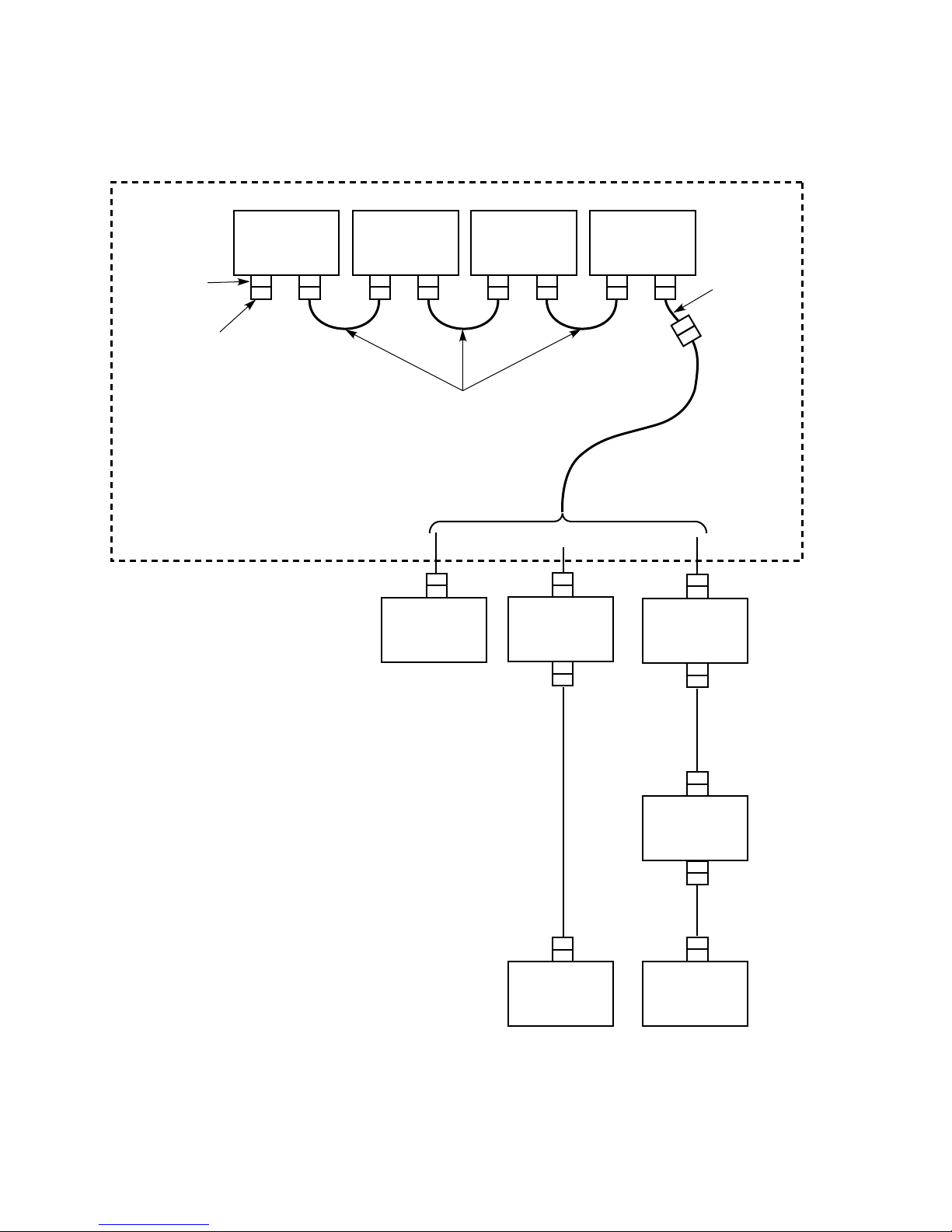
Figure 1–1 Storage-Only Cabinet SCSI Bus Arrangements
REAR PANEL
SCSI
CONNECTORS
H8574A
TERMINATOR
StorageWorks CABINET
TZ8x7-SERIES
TAPE DRIVE
TZ8x7-SERIES
TAPE DRIVE
BC19J-1E
JUMPER CABLE
(.5 METER LENGTH)
HOST
(NEAR)
TZ8x7-SERIES
TAPE DRIVE
SINGLE-ENDED INTERFACE
DWZZA-AA
SCSI SIGNAL
CONVERTER
TZ8x7-SERIES
TAPE DRIVE
CONTROLLER CABLE
(BN21H-xx SCSI A
CABLE-LENGTH TO
SUIT APPLICATION)
17-03831
ADAPTER
CABLE
(.2 METER
LENGTH)
DWZZA-AA
SCSI SIGNAL
CONVERTER
BN21K
OR
BN21L
SCSI P CABLE
(DIFFERENTIAL
INTERFACE)
BN21H-xx
SCSI A CABLE
(SINGLE-ENDED
INTERFACE)
CXO-4049A-MC
SCSI P CABLE
(DIFFERENTIAL
HOST
(DISTANT)
BN21K
OR
BN21L
INTERFACE)
DWZZA-AA
SCSI SIGNAL
CONVERTER
HOST
(DISTANT)
For more detailed information on the use of DWZZA–AA SCSI signal converters,
see the StorageWorks Family User’s Guide.
1–2 TZ8x7-Series Tape Drive SCSI Buses
Page 5
Section 2.2 presents further information on the planning and installation of
TZ8x7-series tape drive buses in StorageWorks storage-only cabinets.
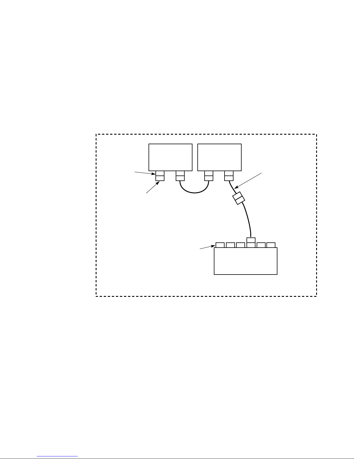
1.1.2 Controller/Storage Cabinet Configurations
In a controller/storage cabinet configuration, the controller for devices in the
cabinet is located within the cabinet. The SCSI bus arrangement for TZ8x7-series
tape drives in StorageWorks controller/storage cabinets is shown in Figure 1–2.
Figure 1–2 Controller/Storage Cabinet SCSI Bus Arrangement
REAR PANEL
SCSI
CONNECTORS
H8574A
TERMINATOR
StorageWorks CABINET
TZ8x7-SERIES
TAPE DRIVE
BC19J-1E
JUMPER CABLE
(.5 METER LENGTH)
CONTROLLER
DEVICE PORT
CONNECTORS
TZ8x7 -SERIES
TAPE DRIVE
17-03831
ADAPTER CABLE
(.2 METER LENGTH)
CONTROLLER CABLE
(BN21H-xx SCSI A
CABLE-LENGTH TO
SUIT APPLICATION)
HS-FAMILY
CONTROLLER
CXO-4050A-MC
One or two TZ8x7-series tape drives may be installed in a controller/storage
cabinet. The tape drives may be configured on one or two SCSI buses. The
units are serially connected using an adapter cable and one jumper cable, and a
controller cable connects the tape drive bus to the controller within the cabinet.
A terminator is installed on the last tape drive on the bus.
Section 2.3 presents further information on the planning and installation of
TZ8x7-series tape drive SCSI buses in StorageWorks controller/storage cabinets.
TZ8x7-Series Tape Drive SCSI Buses 1–3
Page 6

1.2 TZ8x7-Series Tape Drive Bus Connections
The TZ8x7-series tape drive connects to its host system or controller using a
single-ended, narrow, SCSI bus. The approximate transfer rate for the tape drive
is 3 MB per second, allowing a SCSI bus length of up to 6 meters (19.7 feet).
Two connectors on the rear panel of the TZ8x7-series tape drive are provided
to connect the unit to its SCSI bus. Figure 1–3 shows the location of the SCSI
connectors.
Figure 1–3 TZ8x7-Series Tape Drive Bus Connections
ADDRESS SWITCH
(MAY BE ON OTHER
SIDE ON SOME MODELS)
50-PIN, LOW-DENSITY,
FEMALE CONNECTORS
(BAIL LOCKS)
H8574-A TERMINATOR
17-03831 ADAPTER
CABLE
TZ8x7-SERIES
TAPE DRIVE
REAR PANEL
SCSI A
CABLE
CXO-4047A-MC
CAUTION
Failure to use the 17–03831 adapter cable to connect TZ8x7-series tape
drives to StorageWorks SCSI buses may result in improper system
operation and equipment damage. StorageWorks SCSI buses contain fault
detection signals that could be rendered inoperable if any other cable
arrangement is used. The adapter cable must be installed at the first tape
drive on the bus to prevent improper system operation and equipment
damage.
1–4 TZ8x7-Series Tape Drive SCSI Buses
Page 7

The rear panel connectors are 50-pin, low-density, SCSI connectors that do not
mate with standard StorageWorks SCSI A cables. To connect the TZ8x7-series
tape drive to a StorageWorks SCSI bus, you must use an adapter cable (Digital
part number 17–03831). The adapter cable and its installation are shown in
Figures 1–3 and 1–4.
Figure 1–4 TZ8x7-Series Tape Drive Adapter Cable and Terminator
H8574-A TERMINATOR
(50-PIN, LOW-DENSITY,
MALE CONNECTOR [BAIL LOCKS])
17-03831 ADAPTER CABLE
50-PIN, LOW-DENSITY,
MALE CONNECTOR
(BAIL LOCKS)
Use Digital BC19J–1E cables as jumper cables among TZ8x7-series tape drives
within the same cabinet. These cables are .5 meters (1.6 feet) in length. Standard
StorageWorks SCSI A cables are used for the host and controller cables, and their
length is determined as part of the bus planning process. See the StorageWorks
Family Configuration Guide for further information on SCSI A cables. See
Sections 2, 2.2 and 2.3 for detailed TZ8x7-series tape drive bus planning
information.
The H8574–A terminator is used to terminate the tape drive bus. The H8574–A
terminator is shown in Figures 1–3 and 1–4.
5O-PIN, HIGH-DENSITY,
FEMALE CONNECTOR
(THUMB LATCHES)
CXO-4048A-MC
TZ8x7-Series Tape Drive SCSI Buses 1–5
Page 8

Page 9

Planning and Installing a TZ8x7-Series Tape
This chapter presents detailed procedures for planning and installing SCSI buses
for TZ8x7-series tape drives in StorageWorks cabinets.
2.1 General Planning Steps
Following are the general steps required to configure a TZ8x7-series tape drive
bus in a StorageWorks cabinet.
For maximum performance, tape drive buses should contain only tape
drives. Do not mix tape drives and disk drives on the same bus.
1. Determine the number of tape drives to be installed on the bus. This number
is normally limited by the maximum number of tape drives that can be
installed in a specific cabinet.
2
Drive SCSI Bus
Note
2. Determine the quantity of jumper cables to be used to connect the tape drives
to each other within the cabinet.
3. Determine the maximum host or controller cable length using the maximum
allowed total bus length and the lengths of the adapter and jumper cables.
(If the cable length available is insufficient to reach the host, two DWZZA-AA
SCSI signal converters must be used to extend the bus.)
4. Choose the appropriate host or controller cable length, from the available
standard SCSI A cable lengths.
5. Install the tape drives and bus cabling.
6. Set each tape drive’s address switch.
Section 2.2 presents detailed procedures for planning and installing SCSI buses
for TZ8x7-series tape drives in storage-only cabinets. Section 2.3 presents
detailed procedures for planning and installing SCSI buses for TZ8x7-series tape
drives in controller/storage cabinets.
2.2 Planning and Installing Tape Drive Buses In Storage-Only
Cabinets
The following sections describe the steps necessary to plan and install a
TZ8x7-series tape drive bus in a StorageWorks storage-only cabinet.
Planning and Installing a TZ8x7-Series Tape Drive SCSI Bus 2–1
Page 10

2.2.1 Determining the Number of Tape Drives On the Bus
You can install from one to four TZ8x7-series tape drives in a StorageWorks
storage-only cabinet, depending upon the model of the cabinet. See the
installation and user’s guide for your specific cabinet for instructions on the
number and location of tape drives in the cabinet. The tape drives may be
configured on one or more buses, but each tape drive bus should contain only tape
drives. For maximum performance, do not mix tape drives and disk drives on the
same bus.
2.2.2 Determining the Quantities of Adapter and Jumper Cables
CAUTION
Failure to use the 17–03831 adapter cable to connect TZ8x7-series tape
drives to StorageWorks SCSI buses may result in improper system
operation and equipment damage. StorageWorks SCSI buses contain
fault detection signals that could be rendered inoperable if any other
cable arrangement is used. The adapter cable must be installed at the
first tape drive on the bus to prevent improper system operation and
equipment damage.
The number of jumper cables required is one less than the number of tape drives
on the bus. One adapter cable must be used on the first tape drive on the bus to
connect it to the host cable.
2.2.3 Determining the Maximum Host Cable Length
To determine the host cable length, add up the lengths of the adapter cable and
all of the jumper cables and subtract it from the maximum total bus length of 6
meters (19.7 feet). The result is the maximum length of the host cable.
Example 2–1 shows the tape drive SCSI bus length calculation for the bus with
four tape drives shown in Figure 1–1.
Example 2–1 Storage-Only Cabinet Tape Drive SCSI Bus Length Calculation
total number of adapter cables = 1
total adapter cable length = 1 x .2 meters = .2 meters
total number of jumper cables = 3
total jumper cable length = 3 x .5 meters = 1.5 meters
total adapter and jumper cable length = 1.7 meters
Maximum SCSI bus length = 6 meters
Maximum length of SCSI A cable from adapter cable to host
(or DWZZA-AA SCSI Signal Converter) = 6 - 1.7 = 4.3 meters
2.2.4 Choosing the Host Cable
Using the StorageWorks Family Configuration Guide, choose the SCSI A cable
that is nearest in length but less than the length you calculated in Section 2.2.3.
In Example 2–1, for instance, you would choose a BN21H–03, 3-meter cable as
the nearest standard cable.
2–2 Planning and Installing a TZ8x7-Series Tape Drive SCSI Bus
Page 11

Note that TZ8x7-series tape drives are always physically installed in the upper
portion of the StorageWorks cabinet. Some host cable length is consumed by
the cable run from the first tape drive on the bus to the bottom of the cabinet.
This distance is approximately 2 meters for SW800 cabinets, and 1 meter for
SW500 cabinets. If your chosen host cable cannot reach from the tape drives to
the host taking the internal cable run into account, two DWZZA–AA SCSI signal
converters must be used to extend the bus. See the StorageWorks Family User’s
Guide for further information on using DWZZA–AA SCSI signal converters to
extend single-ended SCSI buses.
In the case where the host uses a differential SCSI bus, a DWZZA–AA SCSI
signal converter must be used to convert the differential bus to a single-ended
bus for use by the tape drives (refer to Figure 1–1). The signal converter should
be placed in or near the base of the StorageWorks cabinet to minimize the singleended bus length. The host cable must be long enough to reach from the first
tape drive on the bus to the signal converter at the base of the cabinet. (Note
that the host must operate in the 8-bit differential mode to function properly with
the DWZZA–AA SCSI signal converter.)
2.2.5 Installing the Tape Drives and Cabling
See the installation and user’s guide for your specific StorageWorks cabinet model
for detailed tape drive mechanical installation information. Using Figure 1–1 as
a guide, install adapter and jumper cables to interconnect the tape drives within
the cabinet. Install the terminator on the last tape drive on the bus.
You may use either connector on the rear panel to connect the tape drive to a
SCSI bus. The remaining connector may be used either to extend the bus to
additional devices or to terminate the bus with a H8574–A terminator.
Route the host cable from the bus’s first tape drive adapter cable to the base
of the cabinet using the guidelines in the cabinet’s installation and user guide.
Connect the cable to either the host or the signal converter, as appropriate.
2.2.6 Setting the Address Switch
Each tape drive has a SCSI bus address switch located on the rear panel next to
its bus connectors (refer to Figure 1–3). The address switch may be located on
either side of the connectors. The address switch on each tape drive must be set
to a different value to avoid bus conflicts.
Normally, TZ8x7-series tape drives are addressed in sequence, starting from
address 0 to address 3. Addresses 4 and 5 may also be used if desired, but
addresses 6 and 7 should be reserved for bus initiator use.
Using a pen or other small stylus, set the address switch on each tape drive.
See the installation and user’s guide for your specific TZ8x7-series tape drive for
detailed instructions on setting the address switch.
2.3 Planning and Installing Tape Drive Buses In Controller/Storage
Cabinets
The following sections describe the steps necessary to plan and install a
TZ8x7-series tape drive bus in a StorageWorks controller/storage cabinet.
Planning and Installing a TZ8x7-Series Tape Drive SCSI Bus 2–3
Page 12

2.3.1 Determining the Number of Tape Drives On the Bus
You can install one or two TZ8x7-series tape drives in a StorageWorks
controller/storage cabinet. See the installation and user’s guide for your specific
cabinet for instructions on the number and location of tape drives in the cabinet.
The tape drives may be configured on one or two buses, but each tape drive bus
should contain only tape drives. For maximum performance, do not mix tape
drives and disk drives on the same bus.
2.3.2 Determining the Quantities of Adapter and Jumper Cables
CAUTION
Failure to use the 17–03831 adapter cable to connect TZ8x7-series tape
drives to StorageWorks SCSI buses may result in improper system
operation and equipment damage. StorageWorks SCSI buses contain
fault detection signals that could be rendered inoperable if any other
cable arrangement is used. The adapter cable must be installed at the
first tape drive on the bus to prevent improper system operation and
equipment damage.
One jumper cable is required if two tape drives are being installed on the bus.
One adapter cable must be used on the first tape drive on the bus to connect it to
the host cable.
2.3.3 Determining the Maximum Controller Cable Length
To determine the controller cable length, add up the lengths of the adapter and
jumper cables and subtract it from the maximum total bus length of 6 meters
(19.7 feet). The result is the maximum length of the controller cable.
Example 2–2 shows the tape drive SCSI bus length calculation for the bus with
two tape drives shown in Figure 1–2.
Example 2–2 Controller/Storage Cabinet Tape Drive SCSI Bus Length
Calculation
total number of adapter cables = 1
total adapter cable length = 1 x .2 meters = .2 meters
total number of jumper cables = 1
total jumper cable length = 1 x .5 meters = .5 meters
total adapter and jumper cable length = .7 meters
Maximum SCSI bus length = 6 meters
Maximum length of SCSI A cable from adapter cable
to controller = 6 - .7 = 5.3 meters
2.3.4 Choosing the Controller Cable
Using the StorageWorks Family Configuration Guide, choose a SCSI A cable that
is less than the length you calculated in Section 2.3.3. Because the tape drives
and controller in this case are in the same cabinet and are likely less than 1 or
2 meters from each other, choose the shortest cable that will reach between the
units. In Example 2–2, for instance, you might choose a BN21H–01, 1-meter
cable. See the installation and user’s guide for your specific cabinet for guidelines
on the locations of tape drives and controllers in the cabinet.
2–4 Planning and Installing a TZ8x7-Series Tape Drive SCSI Bus
Page 13

2.3.5 Installing the Tape Drives and Cabling
See the installation and user’s guide for your specific StorageWorks cabinet model
for detailed tape drive mechanical installation information. Using Figure 1–2 as
a guide, install adapter and jumper cables to interconnect the tape drives within
the cabinet. Install the terminator on the last tape drive on the bus.
You may use either connector on the rear panel to connect the tape drive to a
SCSI bus. The remaining connector may be used either to extend the bus to
additional devices or to terminate the bus with a H8574–A terminator.
Route the controller cable from the bus’s first tape drive adapter cable to the
appropriate controller port using the guidelines in the cabinet’s installation and
user guide. Connect the cable to the controller shelf. See the StorageWorks Array
Controller HS Family of Array Controller User’s Guide for further information on
the connection of SCSI buses to HS-family controllers.
2.3.6 Setting the Address Switch
Each tape drive has a SCSI bus address switch located on the rear panel next to
its bus connectors (refer to Figure 1–3). The address switch may be located on
either side of the connectors. The address switch on each tape drive must be set
to a different value to avoid bus conflicts.
Normally, TZ8x7-series tape drives are addressed in sequence, starting from
address 0 to address 3. Addresses 4 and 5 may also be used if desired, but
addresses 6 and 7 should be reserved for controller use.
Using a pen or other small stylus, set the address switch on each tape drive.
See the installation and user’s guide specific to your TZ8x7-series tape drive for
detailed instructions on setting the address switch.
Planning and Installing a TZ8x7-Series Tape Drive SCSI Bus 2–5
Page 14

 Loading...