

Page 1

DECpc
600-MBSCSICD–ROMDrive
InstallationGuide
Order Number: EK–XCRAA–IG. B03
Digital Equipment Corporation
Maynard, Massachusetts
Page 2

First published, August 1992
Revised, August 1992, October 1992
The information in this document is subject to change without notice and should not be
construed as a commitment by Digital Equipment Corporation. Digital Equipment Corporation
assumes no responsibility for any errors that may appear in this document.
The software described in this document is furnished under a license and may be used or copied
only in accordance with the terms of such license.
No responsibility is assumed for the use or reliability of software on equipment that is not
supplied by Digital Equipment Corporation or its affiliated companies.
Restricted Rights: Use, duplication, or disclosure by the U.S. Government is subject to
restrictions as set forth in subparagraph (c)(1)(ii) of the Rights in Technical Data and Computer
Software clause at DFARS 252.227-7013.
The following are trademarks of Digital Equipment Corporation: Digital, DECdirect, DECpc,
ULTRIX, VMS, RRD42, and the Digital logo.
Adaptec ASW410, Adaptec ASW1210, and Adaptec ASW1410 are trademarks of Adaptec,
Incorporated. ASPI DOS Manager is a trademark of Atlanta Signal Processors, Incorporated.
Microsoft and MS–DOS are registered trademarks and Windows is a trademark of Microsoft
Corporation. OS/2 is a registered trademark of International Business Machines Corporation.
© Digital Equipment Corporation 1992.
All Rights Reserved.
Printed in U.S.A.
This document was prepared using VAX DOCUMENT, Version 2.1.
Page 3

Contents
1 Introduction
2 Package Contents
3 Preinstallation
Determining Your Adapter Type ............................... 3–1
Removing the Mode Select Jumper . . ........................... 3–3
Setting the SCSI ID Jumpers ................................. 3–4
Attaching Mounting Brackets ................................. 3–6
4 Completing the Installation
Mounting the Drive ......................................... 4–1
Providing SCSI Bus Termination ............................... 4–1
Connecting the SCSI Cable ................................... 4–6
Connecting the Power Cable .................................. 4–7
5 Installing Device Drivers
Loading Device Driver Files ................................... 5–1
Editing the CONFIG.SYS File ................................. 5–2
Editing the STARTNET.BAT File ............................... 5–3
Editing the AUTOEXEC.BAT File . . . ........................... 5–4
iii
Page 4

6 Using the RRD42 CD–ROM Drive
Controls and Indicators ...................................... 6–1
Inserting a Disk into the Drive ................................ 6–3
Manually Ejecting the Caddy . . ................................ 6–7
Caring for Your Drive and Disks ............................... 6–8
A Specifications
Examples
3–1 Adaptec Device Driver Display........................ 3–6
Figures
2–1 PCXCA–AA Kit Contents ............................ 2–2
3–1 SCSI Host Adapter Boards. . . ........................ 3–2
3–2 Mode Select Jumper ................................ 3–3
3–3 Setting the SCSI ID Jumpers ........................ 3–5
4–1 SCSI Terminator at the End of the SCSI Cable ........... 4–2
4–2 Connecting the SCSI Cable with the Termination
Connector ........................................ 4–3
4–3 Removing SCSI Termination Resistors from a Hard Drive. . 4–4
4–4 Removing SCSI Termination Resistors from the Adapter
Board . . ........................................ 4–5
4–5 Inverting the SCSI Connector by Folding the Cable ....... 4–6
4–6 Connecting the Power Cable . ........................ 4–7
6–1 Front Panel of the CD–ROM Drive .................... 6–1
6–2 Opening the Caddy ................................ 6–3
6–3 Inserting a Disk into the Caddy ....................... 6–4
6–4 Closing the Caddy . ................................ 6–5
6–5 Inserting the Caddy into the Drive .................... 6–6
6–6 Manually Ejecting the Caddy . ........................ 6–7
iv
Page 5

Tables
3–1 SCSI Adapter Order Numbers ........................ 3–2
5–1 Copying Device Driver Files .......................... 5–1
5–2 Adding Lines to Your CONFIG.SYS File ................ 5–2
5–3 MSCDEX.EXE Software Switches . . ................... 5–5
6–1 Front Panel Controls and Indicators ................... 6–2
A–1 RRD42 CD–ROM Drive Specifications .................. A–1
v
Page 6

Page 7

1
Introduction
The RRD42 disk drive is a half-height, 5¼-inch, Compact Disk – Read-Only
Memory (CD–ROM) device. It connects to your personal computer (PC) with
the Small Computer System Interconnect (SCSI) bus.
You can use the drive to play audio CDs as well as to read computer data CDs.
To listen to audio CDs, use software such as the Media Player application
included with Microsoft Windows, Version 3.1.
The drive has the following features:
• 600-MB capacity
• Data transfer rate of 150 KB per second
• Burst rate of 1.5 MB per second
• Average seek time of less than 500 milliseconds
• Audio output jacks and a headphone jack
1–1
Page 8

Page 9

2
Package Contents
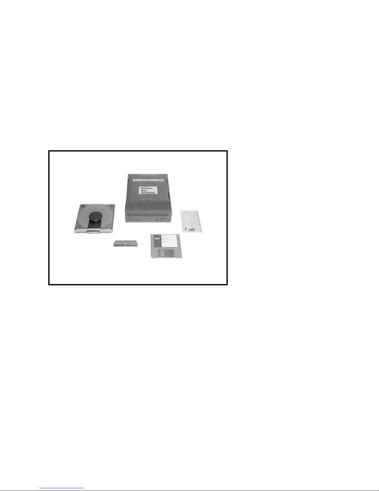
The CD–ROM drive kit (order number PCXCA–AA) contains the following
items (Figure 2–1):
• CD–ROM drive (order number RRD42–AA)
• Caddy for a compact disk (CD) (order number RRD4X–CA/CDA for a pack
of five caddies)
• SCSI bus termination connector
• Screws for mounting the CD–ROM drive
• Diskette(s) with device driver software
2–1
Page 10
Package Contents
Figure 2–1 PCXCA–AA Kit Contents
CD-ROM Caddy
CD-ROM Drive
SCSI Bus
Termination
Connector
Screws
Device Driver
Software
LJ-0151-FH
2–2
Page 11

Determining Your Adapter Type
To install the CD–ROM drive, you must have one of the following Adaptec
SCSI host adapter boards in your PC:
• AHA–1510
• AHA–1520
• AHA–1540
• AHA–1740
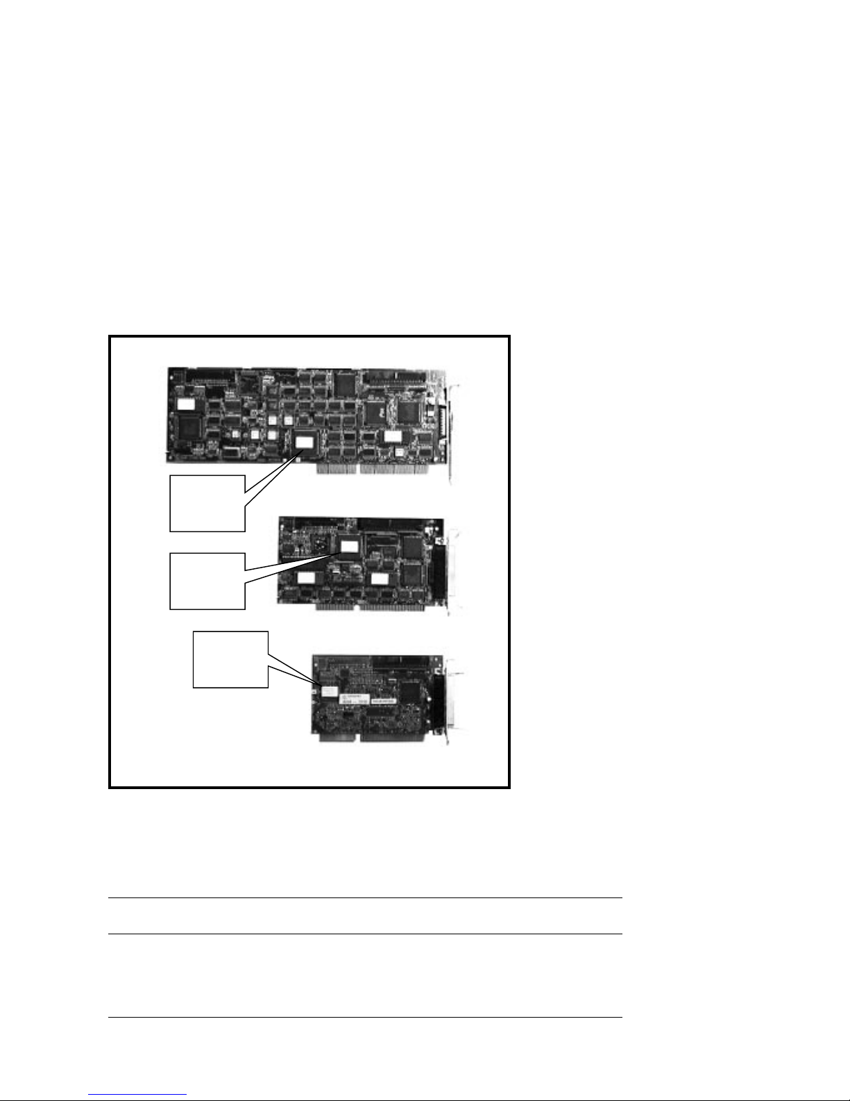
If you are not sure whether you have one of these adapter boards, remove the
cover of your PC and check now. Some of these adapter boards are shown in
Figure 3–1. Make a note of which board you have because you will need this
information later to install the correct device driver software.
3
Preinstallation
3–1
Page 12
Preinstallation
Figure 3–1 SCSI Host Adapter Boards
AHA-1740
AHA-1540B
3–2
AHA-1510
LJ-0152-FH
If you do not have one of these SCSI host adapters boards, you must install
one. The order numbers for new adapter boards are listed in Table 3–1.
Table 3–1 SCSI Adapter Order Numbers
Adaptec
Number
AHA–1520 PCTAZ–AA Basic adapter
AHA–1540 PCTAZ–AD Higher performance adapter with Direct Memory Access
AHA–1740 PCTAZ–AB Adapter for use with 32-bit EISA bus only
Digital Order
Number Description
(DMA) capabilities
Page 13

Removing the Mode Select Jumper
The mode select jumper on the back of the CD–ROM drive sets the data
transfer block size to 512 bytes for use with VMS and ULTRIX operating
systems or 2 kilobytes for use with MS–DOS and OS/2 operating systems.
Set the block size to 2 kilobytes by removing the mode select jumper and
placing it on the lower pin for storage (Figure 3–2). Use a small knife or other
sharp object such as a bent paper clip to poke under the jumper and lift it off
the pins.
Figure 3–2 Mode Select Jumper
Mode Select
Jumper Removed
Preinstallation
Rear of CD-ROM drive with mode select jumper shown
LJ-0160-FH
3–3
Page 14

Preinstallation
Setting the SCSI ID Jumpers
The SCSI bus on your Adaptec SCSI host adapter board can connect up to
seven disk, tape, or other SCSI devices. Each of these devices must have a
different SCSI ID number.
Check to see whether you have other SCSI devices connected to your Adaptec
SCSI host adapter board. One or more internal SCSI devices can be connected
to the ribbon cable at the top edge of the adapter board. External SCSI devices
can be connected to the adapter board at the back panel of your PC.
The number of devices on your SCSI bus will be like one of the following two
cases:
• CASE 1: If you have no other devices connected to your SCSI adapter, set
the SCSI ID of your CD–ROM drive to 0. To set the ID to 0, remove all
three jumpers and place them in the storage position on the lower pins
(Figure 3–3). Any SCSI ID from 0 to 6 will work, but with settings other
than 0, the boot time will be many seconds longer when you turn on your
PC.
• CASE 2: If you have other SCSI devices already attached to your Adaptec
SCSI host adapter board, you must choose a SCSI ID for your CD–ROM
drive that is not already used by one of the other devices. If you do not
know the SCSI IDs of the other devices, reboot your PC and watch the
Adaptec device driver program display the information on your screen.
As your PC reboots, watch for a line with ‘‘ASPI Manager for DOS.’’ You
should see something like Example 3–1.
3–4
Page 15

Figure 3–3 Setting the SCSI ID Jumpers
Preinstallation
SCSI ID 0
SCSI ID 1
SCSI ID 2
SCSI ID 3
SCSI ID 4
012 210
SCSI ID 5
210210
SCSI ID 6
210210
SCSI ID 7
210210
LJ-0161-FH
3–5
Page 16

Preinstallation
Example 3–1 Adaptec Device Driver Display
AHA--1540/1542/1640 ASPI Manager for DOS
Version 3.0
Copyright 1991 Adaptec, Inc.
Int 13 H routed through ASPI manager
ASPI4DOS.SYS Installation Successful
Host Adapter #: 0 Host Adapter SCSI ID: 7
!
I/O Port Address 330 DMA Channel: 5
Interrupt Level: 11 VDS Support Level: MultiSegRW
Host Adapter #0 - SCSI ID 0 - LUN 0:QUANTUM P40S 940-40-94xx
Host Adapter #0 - SCSI ID 1 - LUN 0:QUANTUM P105S 910-10-94xx
"
#
Int 13H active for drive C: and D:
In Example 3–1, the SCSI host adapter board is using SCSI ID 7 (!). Two
other devices are on the SCSI bus ("and#). They are both Quantum disk
drives and their SCSI IDs are 0 and 1. In this case, you can set the ID for
your CD–ROM drive to any number from 2 to 6 (Figure 3–3).
If the ‘‘ASPI Manager for DOS’’ line is displayed, but you do not get
information about the device SCSI IDs, then follow these steps:
1. Edit your CONFIG.SYS file.
2. Find the line that looks like:
DEVICE=C:\SYS\ASPI4DOS.SYS
This line may have ‘‘ASPI2DOS.SYS,’’ ‘‘ASPI4DOS.SYS,’’ or
‘‘ASPIEDOS.SYS.’’
3. Add the /D switch (Display) to the line:
DEVICE=C:\SYS\ASPI4DOS.SYS /D
4. Reboot your PC and watch for the device SCSI ID information.
Attaching Mounting Brackets
Attach mounting brackets to your CD–ROM drive with the screws provided in
this kit. The mounting brackets are not included in this kit and should have
come with your PC. Instructions for attaching the mounting brackets should
also have come with your PC.
3–6
Page 17

Completing the Installation
Mounting the Drive
Mount the CD–ROM drive in a 5¼-inch bay.
Depending on the layout of your PC, it may be easier to connect the
cables before or after you mount the drive in the bay. The instructions
for mounting the drive in a bay should have come with your PC.
Providing SCSI Bus Termination
You must have termination resistors at each end of the SCSI bus. In its fullest
configuration, the SCSI bus extends:
1. From the last external SCSI device outside your PC
2. To the rear connector on your Adaptec SCSI host adapter board
4
Note
3. Through the adapter board to the internal SCSI ribbon cable
4. To the last device on the internal SCSI ribbon cable
4–1
Page 18

Completing the Installation
The configuration of your SCSI bus will be like one of the following five cases:
• CASE 1: If you have a SCSI terminator at the end of your SCSI ribbon
cable (Figure 4–1), this takes care of your bus termination requirements.
Connect your CD–ROM drive to any other connector on the SCSI cable.
Figure 4–1 SCSI Terminator at the End of the SCSI Cable
SCSI Cable
Terminator
4–2
LJ-0170-FH
Page 19

Completing the Installation
• CASE 2: If you have no SCSI devices connected to your SCSI host adapter
board and your SCSI cable has no terminator, follow these steps:
1. Insert the SCSI termination connector (included in this kit) into the
CD–ROM drive and then connect the SCSI cable to the connector
(Figure 4–2).
2. Connect the other end of the SCSI cable to the SCSI host adapter
board. The SCSI termination resistors in the SCSI host adapter board
are installed at the factory.
Figure 4–2 Connecting the SCSI Cable with the Termination Connector
CD-ROM Drive
Rear View
SCSI
Termination
Connector
SCSI Cable
LJ-0162-FH
4–3
Page 20

Completing the Installation
• CASE 3: If you already have internal SCSI devices connected to the SCSI
host adapter board, you have no SCSI terminator on your SCSI cable, and
you are connecting your CD–ROM drive near the end of the SCSI cable
past your last device, you must follow these steps:
1. Insert the SCSI termination connector into your CD–ROM drive.
2. Remove the termination resistors from the SCSI device that was
previously the last device on the SCSI bus.
For most SCSI devices, the termination resistors are in three resistor packs
that are next to the SCSI connector (Figure 4–3).
Figure 4–3 Removing SCSI Termination Resistors from a Hard Drive
SCSI
Termination
Resistors
Bottom of
Hard Drive
4–4
LJ-0163-FH
Page 21

Completing the Installation
• CASE 4: If you are connecting the CD–ROM drive to the middle of the
SCSI bus so that another device remains at the end of the bus, connect
the SCSI cable directly to the CD–ROM drive without using the SCSI
termination connector.
• CASE 5: If you have only external SCSI devices connected to your SCSI
host adapter board and are installing the CD–ROM drive on the internal
SCSI ribbon cable, you must follow these steps:
1. Remove the termination resistors from the adapter board (Figure 4–4).
2. Connect one end of the SCSI cable to the SCSI host adapter board.
3. If you have a SCSI terminator at the end of your SCSI cable,
connect the SCSI cable to the CD–ROM drive without using the
SCSI termination connector.
4. If you do not have a SCSI terminator at the end of your SCSI cable,
insert the SCSI termination connector into your CD–ROM drive. Then
connect the SCSI cable to the termination connector.
Figure 4–4 Removing SCSI Termination Resistors from the Adapter Board
SCSI
T ermination
Resistors
SCSI Adapter
Board
LJ-0164-FH
4–5
Page 22

Completing the Installation
Connecting the SCSI Cable
Connect the internal SCSI ribbon cable to the CD–ROM drive. Note the
following conditions:
• The edge of the cable with the colored stripe must be connected to pin 1
of the connector. The cable and connector are keyed so that you cannot
connect them backwards.
• The SCSI ribbon cable may have more than one connector. It does not
matter which connector you use.
• The SCSI connector on the CD–ROM drive is up-side-down compared to
the connectors on most disk drives. If you must twist the cable to connect
it, you can make a neat, compact twist by folding the cable as shown in
Figure 4–5.
Figure 4–5 Inverting the SCSI Connector by Folding the Cable
2
1
B
2 3 4
B
BA
ABA
4–6
A
Completed Fold
LJ-0165-FH
Page 23

Connecting the Power Cable
Connect the 4-pin power cable to the CD–ROM drive (Figure 4–6).
Figure 4–6 Connecting the Power Cable
Completing the Installation
Power Cable
LJ-0153-FH
4–7
Page 24

Page 25

Loading Device Driver Files
Copy the device driver files from the diskette(s) into your system area. Which
files you must copy depends on which Adaptec SCSI host adapter board
you have. Table 5–1 lists which files to copy. The device driver kits in the
table may be subdirectories on a single diskette or they may be on separate
diskettes.
Table 5–1 Copying Device Driver Files
If You Have Copy These Files
5
Installing Device Drivers
AHA–1510 or
AHA–1520
AHA–1540 or
AHA–1740 (16-bit mode)
AHA–1740 (32-bit mode) ASPIEDOS.SYS from the ASW1410 device driver kit
ASPI2DOS.SYS from the ASW1210 device driver kit
ASWCDDEC.SYS and MSCDEX.EXE from the ASW410
device driver kit
ASPI4DOS.SYS from the ASW1410 device driver kit
ASWCDDEC.SYS and MSCDEX.EXE from the ASW410
device driver kit
ASWCDDEC.SYS and MSCDEX.EXE from the ASW410
device driver kit
5–1
Page 26

Installing Device Drivers
Editing the CONFIG.SYS File
Make the following changes to your CONFIG.SYS file:
1. Some earlier SCSI host adapters used a device driver called SCSIHA.SYS.
If your CONFIG.SYS file has a line with ‘‘SCSIHA.SYS’’ such as
DEVICE=C:\SYS\SCSIHA.SYS, delete the line.
2. Add two new lines to your CONFIG.SYS file (unless you already have these
lines). These lines should go at the beginning of the file, after the lines
‘‘BUFFERS=n’’ and ‘‘FILES=n’’. The lines you must add depend on which
SCSI host adapter board you have (Table 5–2).
Table 5–2 Adding Lines to Your CONFIG.SYS File
SCSI Host Adapter Board Lines to Add
AHA–1510 or
AHA–1520
AHA–1540 or
AHA–1740 (16-bit mode)
AHA–1740 (32-bit mode)
DEVICE=C:\SYS\ASPI2DOS.SYS /D
DEVICE=C:\SYS\ASWCDDEC.SYS /D:CDROM
DEVICE=C:\SYS\ASPI4DOS.SYS /D
DEVICE=C:\SYS\ASWCDDEC.SYS /D:CDROM
DEVICE=C:\SYS\ASPIEDOS.SYS /D
DEVICE=C:\SYS\ASWCDDEC.SYS /D:CDROM
If you have a line with ‘‘ASPIDISK.SYS’’ in your CONFIG.SYS file, add one
new line before and the other new line after the ASPIDISK.SYS line, as
follows:
DEVICE=C:\SYS\ASPIxDOS.SYS /D
DEVICE=C:\SYS\ASPIDISK.SYS
DEVICE=C:\SYS\ASWCDDEC.SYS /D:CDROM
The /D switch in the ASPIxDOS.SYS line is an optional switch that causes
the device driver to display more information on your screen when you turn
on your PC.
The /D:CDROM switch in the ASWCDDEC.SYS line specifies a device
name, ‘‘CDROM’’ in this case, for your CD–ROM drive. You can use any
name you like, but it must be the same as the name that you enter in the
MSCDEX.EXE line in your STARTNET.BAT or AUTOEXEC.BAT file. If
you have more than one CD–ROM drive, add a /D: switch with a different
device name for each drive.
5–2
Page 27

Editing the STARTNET.BAT File
The Microsoft CD–ROM Extension program, MSCDEX.EXE, loads the device
driver for your CD–ROM drive(s). You use MSCDEX.EXE for connection to
remote CD–ROM drives on the network as well as to local CD–ROM drives in
your PC.
Only one of your system boot files, STARTNET.BAT or AUTOEXEC.BAT,
should run MSCDEX.EXE. To determine in which file to place the
MSCDEX.EXE line, perform the following steps:
1. Check to see if your system boot uses a STARTNET.BAT file by searching
your AUTOEXEC.BAT for the line ‘‘CALL \DECNET\STARTNET’’.
If you do not have this line, add the MSCDEX.EXE line to your
AUTOEXEC.BAT file. See the next section, Editing the AUTOEXEC.BAT
File.
2. If your system boot does use a STARTNET.BAT file, check to see if an
MSCDEX.EXE line is already in your STARTNET.BAT file. The line looks
like this:
%_SYSD%\LMDOS\DRIVERS\PCSA\MSCDEX.EXE /D:$LADCD /E
If you do not have this line, add the MSCDEX.EXE line to your
AUTOEXEC.BAT file. See the next section, Editing the AUTOEXEC.BAT
File.
Installing Device Drivers
3. If you do have an MSCDEX.EXE line in your STARTNET.BAT file, edit the
line by adding a /D switch for each CD–ROM drive that you are installing.
The line should look like this:
%_SYSD%\LMDOS\DRIVERS\PCSA\MSCDEX.EXE /D:$LADCD /E /D:CDROM
The device name(s), ‘‘CDROM’’ in this case, must be the same as the device
name(s) that you used in the ASWCDDEC.SYS line in your CONFIG.SYS
file.
You can specify a drive letter for your CD–ROM drive with the /L switch as
shown:
%_SYSD%\LMDOS\DRIVERS\PCSA\MSCDEX.EXE /D:$LADCD /E /D:CDROM /L:G
In this example, if you had two remote CD–ROM drives and one local
CD–ROM drive, the remote drives would be drives G and H and the local
drive would be drive I.
You can use the PATHWORKS command USE /STATUS to get a list of all of
your drive letter assignments.
5–3
Page 28

Installing Device Drivers
Editing the AUTOEXEC.BAT File
Make the following changes to your AUTOEXEC.BAT file only if you do not
have an MSCDEX.EXE line in your STARTNET.BAT file:
1. Add the following line:
C:\SYS\MSCDEX.EXE /D:CDROM /M:12 /V /L:R
Be sure to include the spaces in the line. If you have a network
operating system such as the PATHWORKS network operating system,
you must enter the MSCDEX.EXE line after any file redirector. In
the case of PATHWORKS, place the MSCDEX.EXE line after the
CALL \DECNET\STARTNET line as follows:
CALL \DECNET\STARTNET
C:\SYS\MSCDEX.EXE /D:CDROM /M:12 /V /L:R
The MSCDEX.EXE software switches have the functions described in
Table 5–3.
2. If you use PATHWORKS and your PC connects to Local Area Disk (LAD)
drives, you must also add USE /UNFIX to your AUTOEXEC.BAT file.
To determine whether you have LAD drives, search for the line
‘‘DEVICE=C:\DECNET\LADDRV.SYS’’ in your CONFIG.SYS file. If you
have this line, add USE /UNFIX to your AUTOEXEC.BAT file as shown:
CALL \DECNET\STARTNET
USE /UNFIX
C:\SYS\MSCDEX.EXE /D:CDROM /M:12 /V /L:R
The USE /UNFIX line reserves the drive letters that the network software
assigns to the LAD drives. Without USE /UNFIX, MSCDEX.EXE may
assign a LAD drive letter to your CD–ROM drive.
5–4
Page 29

Table 5–3 MSCDEX.EXE Software Switches
Switch Function
Installing Device Drivers
/D Specifies the device name that you used in the ASWCDDEC.SYS line in
/M:12 Specifies the number of memory buffers.
/V Specifies verbose mode, which displays more information on your screen
/L:R Specifies the drive letter for your CD–ROM drive, drive ‘‘R’’ in this case.
/E Tells the MSCDEX.EXE program to use expanded memory if your
your CONFIG.SYS file. Include one /D switch for each of your CD–ROM
drives.
when you turn on your PC.
If you omit this switch, your CD–ROM drive will be assigned the next
available drive letter after your hard disk drives, reserved LAD drives,
and connected remote file services.
system is using expanded memory.
5–5
Page 30

Page 31

Using the RRD42 CD–ROM Drive
Controls and Indicators
Figure 6–1 shows the front panel of the CD–ROM drive and Table 6–1
describes the controls and indicators.
Figure 6–1 Front Panel of the CD–ROM Drive
Caddy
Insertion Slot
6
Headphone
Jack
Headphone
Level
Control
Dimple for
ID Number
Label
Busy
Indicator
Eject
Button
Emergency
Eject
Hole
LJ-0154-FH
6–1
Page 32

Using the RRD42 CD–ROM Drive
Table 6–1 Front Panel Controls and Indicators
Controls/Indicators Function
Headphone jack Accepts a headphone connector.
Headphone level control Adjusts the volume.
Caddy insertion slot Accepts a caddy loaded with a disk.
Dimple You may place a drive letter label (not included) here.
Busy indicator Lights when data is read from the disk and blinks during
Eject button Ejects the caddy from the drive.
Emergency eject hole Allows you to eject the caddy manually from the drive when
seek operations.
the power is off.
6–2
Page 33

Inserting a Disk into the Drive
Follow these steps to insert a disk into the CD–ROM drive:
1. If a protective film is on the lid of the caddy, remove the film before using
the caddy.
2. Open the lid of the caddy by pressing the tabs on both sides and lifting the
lid (Figure 6–2).
Figure 6–2 Opening the Caddy
Using the RRD42 CD–ROM Drive
LJ-0155-FH
6–3
Page 34

Using the RRD42 CD–ROM Drive
3. Insert the disk into the caddy with the label up (Figure 6–3).
Hold the disk by the edges. Try not to touch the surface of the disk.
The disk can stand only a limited amount of dirt and oils from your
skin before developing data errors.
Figure 6–3 Inserting a Disk into the Caddy
Caution
6–4
LJ-0156-FH
Page 35

Using the RRD42 CD–ROM Drive
4. Close the lid by pressing both corners firmly (Figure 6–4).
Figure 6–4 Closing the Caddy
LJ-0157-FH
6–5
Page 36

Using the RRD42 CD–ROM Drive
5. Insert the caddy into the drive (Figure 6–5).
Figure 6–5 Inserting the Caddy into the Drive
6–6
LJ-0158-FH
Page 37

Manually Ejecting the Caddy
You can manually eject the caddy when your PC is turned off or during a power
failure by inserting a paper clip or other sturdy object into the emergency eject
hole (Figure 6–6). You must push hard. A large size paper clip works better
than the standard size.
Figure 6–6 Manually Ejecting the Caddy
Using the RRD42 CD–ROM Drive
LJ-0159-FH
6–7
Page 38

Using the RRD42 CD–ROM Drive
Caring for Your Drive and Disks
The RRD42 CD–ROM drive does not require cleaning. However, ensure that
the environment where the drive is installed will be free from dust and dirt.
Avoid placing the disk and caddy in a location subject to:
• Dust
• Direct sunlight
• High temperature
• High humidity
If data errors occur, try cleaning the disk. Wipe the disk from the center
out with a clean, lint-free cloth. If this is not sufficient, clean the disk with
mild soap and water. Do not use solvents, such as benzene, paint thinner,
commercial cleaners, or antistatic sprays.
6–8
Page 39

Specifications
Table A–1 lists the RRD42 CD–ROM drive specifications.
Table A–1 RRD42 CD–ROM Drive Specifications
Characteristic Specification(s)
A
Acceptable disk CD–ROM mode–1 data disk
Rotational speed The drive varies rotational speed as it moves from track
Data transfer rate Sustained rate: 150 KB/s
Access time Full stroke: 0.7 s (typical)
Audio output level Line out: 0.5 V at 47 k
Operating environment Temperature: 5°C (41°F) to 50°C (122°F)
Nonoperating environment Temperature: –30°C (–22°F) to 55°C (131°F)
Host interface SCSI-2
Dimensions 148.5 mm W
CD–ROM mode–2 data disk
CD audio disk
Audio-combined disk
to track.
Innermost track: 530 r/min at constant linear velocity
(CLV) of 1.4 m/s
Outermost track: 200 r/min at CLV of 1.2 m/s
Burst rate: 1.5 MB/s
Average seek: 0.45 s (typical)
Headphone: 0.55 V at 32(at maximum volume)
Humidity: 10% to 90%
Atmosphere: noncondensing
Humidity: 10% to 90%
Atmosphere: noncondensing
2
42.5 mm H2208.2 mm D
2
(5.85 in W
1.67 in H28.2 in D)
(continued on next page)
A–1
Page 40

Using the RRD42 CD–ROM Drive
Table A–1 (Cont.) RRD42 CD–ROM Drive Specifications
Characteristic Specification(s)
Weight 1.3 kg (2.8 lb)
Voltage +5 V dc65% @ 250 mA
+12 V dc
6
10% @ 800 mA
A–2
 Loading...