

Page 1
EK-ORM05-FG-OOl
RM05 Fault
Isolation
Guide
Prepared
Digital Equipment Corporation
by
Educational Services
of
Page 2
Copyright © 1982 by Digital Equipment Corporation
All
Rights Reserved
The material in this manual is for informational purposes and is subject to change
without notice.
Digital Equipment Corporation assumes no responsibility for any errors which
in
may appear
this manual.
Printed in
U.S.A.
• Class A Computing Devices:
Notice:
The equipment has been type tested and found to comply with the
Class A computing device pursuant to Subpart J of Part 15 of FCC Rules, which
are designed to provide reasonable protection against such radio frequency
terference when operated
ment
own expense may
The
chusetts:
This equipment generates, uses, and may emit radio frequency energy.
limits
fc)r
in-
in
a commercial environment. Operation
in
a residential area may cause interference in which case the user at his
of
this equip-
be required to take measures to correct the interference.
following are trademarks of Digital Equipment Corporation, Maynard, Massa-
DEC
DECUS
DIGITAL
Digital Logo
PDP
UNIBUS
VAX
DECnet
DECsystem-10
DECSYSTEM-20
DECwriter
DIBOL
EduSystem
lAS
MASSBUS
OMNIBUS
OS/8
PDT
RSTS
RSX
VMS
VT
a
Page 3
SCOPE
RMSS
FAULT
ISOLATION
GUIDE
This
document
documentation
information.
which
problem
this
The
between
should
cannot
manual,
RMOS
the
has
appl,icable.
Many
or
have
say
accuracy
the
tion
specific
component
been
all
listed
possibilities
of
field.
with
the
is
intended
by
Problems
encompass
be
satisfactorily
the
FSE
a
VDE
two
will
error
(s)
• The
in
t.his
This
document
document
RM05
Field
providing
are
the
is
urged
and
NON-VDE
be
symptoms
most
this
documant.
have
is
Maintenance
to
supplement
additional
listed
majority
to
request
called
can
be
obvious
been
will
be
intended
the
by symptom and
of
all
RMSS
resolved
through
additional
version.
out
in
this
pinpointed
and known
This
of
included.
dependent
to
be
Print
Set.
existing
trou~leshooting
RM05
solution
calls.
the
use
If
a
of
support.
The
to
di
fference
guide
a
module(s)
where
combinations
course
on
used
is
The
inputs
in
not
overall
from
conjunc-
to
i
Page 4
RM95
FAULT
CONTENTS
ISOLATION GUIDE
1.0
2.0
PRELIMINARY ACTION
1.1
1.2
1.3
REQUIRED
GETTING
THINGS
1.3.1
1.3.2
1.3.3
1.3.4
1.3.5
EQUIPMENT
STARTED
TO
BE
AWARE
File
Bad
Corruption
Packs
Environmental
Bus
Loading
Power
Supplies
TROUBLE-SHOOTING AIDS
2.
1
2.2
2.3
ERROR
SITE
CUSTOMER
LOG
MANAGEMENT
DISK
PACK
OF
Problems
GUIDE/LARS
USAGE
LOG
REPORTS
2.4
2.5
ON
LINE DIAGNOSTICS
11/70
2.5.1
2.5.2
2.5.3
2.5.4
2.5.5
2.5.6
2.5.7
2.5.8
DIAGNOSTICS
CERHA
CZRML
CZRMM,
CZRMP,
CZRMR,
CZRMT
CZRMU
CZRMV
N,
Q
S
RH70
Formatter
Functional
0
Diskless
Dual
Compatibility
Performance
Extended
Port
Test
Diagnostic
Logic
Exerciser
Drive
Test
Part
Test
l,
Part
Part.
2,
1 &
1 & 2
&
3
2
11
Page 5
RMes
FAULT
ISOLATION GUIDE
3.9
2.6
POWER
3.1
VAX
DIAGNOSTICS
2.6.1
2.6.2
2.6.3
2.6.4
ON
AND
POWER
3.1.1
3.1.2
3.1.3
EVRAA
EVRAC
EVRDA
EVRDB
MOTOR
ON
PROBLEMS
CB1
CB2
CB3
3.1.3.1
3.1.3.2
CONTENTS
SEQUENCE
Trips
Trips
Trips
When
Immediately
Pressed
(CONT)
Reliability
Disk
RMeX
RM0X
Formatter
Diskless
Functional
CB1
Turned
After
On
Start
Switch
Is
3.1.4
3.1.5
3.1.6
3.1.7
3.1.8
3.1.9
3.1.19
3.1.11
3.1.12
3.1.3.3
CB4
CBS
CB7
CB8
All
+29Y
+28V,
High
-46V,
Low
-46V,
Ripple
Trips
Or
CB6
Trips
Trips
DC
Voltages
-29V,
OR
Low
+46V,
+46V And
Too
Shortly
Squealing
Shortly
Trips
Missing
+29V,
And
-16V
High
For
After
After
-9.7V,
-16V
Are
Just
Noise
Are
Motor
Motor
At
Test
+9.7V
All
Missing
One
Voltage
Turns
Turns
Points
Are
Ei
ther
With
and
Either
High
A
No
All
Or
111
Page 6
RMes
FAULT
ISOLATION GUIDE
3.2
3.
3
DRIVE
3.2.2
3.2.3
POWER
MOTOR
Motor
'Motor
Pressed
3.2.2.1
3.2.2.2
3.2.2.3
3.2.2.4
Motor
ON
AND
CONTENTS
Starts
Does
+20v
A1Q4,
+20V
A1Q4,
+20V
A1Q4,
+20V
but
Overheats
MOTOR~
SEQUENCE
(CONT)
When
Not
missing
missing
OK
OK
208+
Turn
and
and
and
and
CBl
9.7V
9.7V
at
208+
at
Pin
VAC
Thermal
VDE
Is
Turned
When
at
Pin
is
OK
at
Pin
is
missing
Pin
3
VAC
3 Of A1Q2,
is
missing
Cutout
DRIVES
Start
3
3
of
is
On
Switch
of
A1Q2,
of
A1Q2,
A1Q2, A1Q3,
OK
at
Pin
AlQ3,
at
Pin
Activates
Is
AIQ3,
AIQ3,
2
AIQ4
2
3.4
POWER
3.4.1
3.4.2
3.4.3
3.4.4
3.4.5
3.4.6
ON
PROBLEMS
CBl
CB2
CB3
CB4
CBS
CB6
Trips
Trips
Trips
Trips
Trips
or
CB7
Short
When
In
CBl
Immediatley
Turned
Shortly
Also
Shortly
On
After
a
Squealing
After
Trips
+20Y
is
Turned
Distribution
On
After
Motor
Noise
Motor
Start
Starts
Starts
is
Switch
Turning;
Heard
Turing
is
3.4.7
3.4.B
CBB
All
Trips
DC
Voltages
Iv
Missing
and
no
+20Y
Page 7
RM95
FAULT
ISOLATION
GUIDE
3.5
3.4.9
3.4.19
3.4.11
3.4.12
DRIVE
3.5.1
3.5.2
+28v,
High
-46v,
-46v
Ripple
MOTOR
Drive
Drive
Pressed
3.5.2.1
3.5.2.2
3.5.2.3
3.5.2.4
CONTENTS
+29v,
or
Low
and
+46v
and
+46v
too
High
PROBLEMS
Motor
Motor
Starts
Does
+29Y
+29Y
+20Y
Motor
Activates
(CONT)
-20v,
Are
Missing
for
Missing
is
is
-9.7v,
Both
Just
When
not
CB1
Turn
but
but
OK
OK
and
Overheats
+9.7v
High
one
or
Voltage
Is
When
9.7v
9.7v
208
is
VACC
and Terma1
Are
Low
Turned
St.art
OK
is
Missing
is
Either
On
Switch
Ok
Cutout
All
is
4.8
HEAD
4.
1
4.2
4.3
4.4
4.5
4.6
4.7
4.8
4.9
LOAD
SEQUENCE
HEADS
REVERSE
HEADS
DO
REVERSE
CARRIAGE
AND
HEADS
CARRIAGE
AND
HEl~DS
HEADS
(INNER
HEADS
RTZ
:LOAD,
IS
UNABLE
UNABLE
DO
NOT
CURRENT
NOT
CURRENT
HITS
STAY
HITS
RETRACT
LOAD,
GUARD
NON
FUNCTIONAL
TO
SEEK
TO
SEEK
PROBLEMS
LOAD
LOAD
AFTER
IS
AFTER
OK
FORWARD
OUT
ON
FORWARD
HESITATES
BAND)
BUT
UNLOAD,
TO
PRIME
TO
1466
UP
TO
UP
TO
STOP,
CB4
PACK
STOP,
AND
FAULT
THEN
FAULT
CYLINDERS;
(8)
SPEED
SPEED
TRIPS,
CREEPS
LIGHT
TIME
TIME
LIGHT
ON
1,
2,
OUT
OUT
FAULT
ON,
TO
FORWARD
4,
AND
BUT
LIGHT
CB4
- 512
NO
HOLD
ON,
TRIPS
EOT
4.19
UNABLE
TO
FORCE A SEEK
v
ERROR
WITH
FTU
TO
CYL
1467
(8)
Page 8
RM"S
FAULT
ISOLATION GUIDE
5
..
6.9
9
4.11
4.12
PCMER
5.1
5.2
5.3
ERROR
6.1
HEADS
START
DRIVE
AND
DO
LIGHT
MOTOR
POWER
NOT
IS
BRAKE
FAIL
UNLOAD
MASSFAIL
AC
LO -UNSAFE
DC
LO -RM
BITS -CONTROL,
CONTROL
6.1.1
6.1.2
6.1.3
ADAPTER
REGISTER
MCPE
TRE
SC
Bit
Bit
CONTENTS
WHEN
OFF,
PROBLEMS
STATUS
Bit
PACK
IS
INOPERATIVE
176700
13
14
15
(CONT)
START
SPINNING
AND
ERROR
SWITCH
REGISTERS
IS
~TURNED
OFF,
6.2
6.3
STATUS
6.2.1
6.2.2
6.2.3
6.2.4
6.2.5
6.2.6
6.2.7
6.2.8
ERROR
6.3.1
6.3.2
6.3.3
REGISTER
MOPE
MXF
PGE
NEM
NED
PE,
UPE
weE
DLT
REGISTER
ILF
ILR
RMR
176710
Bit
Bit
Bit
Bit
Bit
Bit
Bit
1
Bit
Bit
Bit
08
09
10
11
12
Bit
13
14
15
176714
"0
01
92
6.3.4
6.3.5
PAR
FER
Bit
Bit
"3
04
vi
Page 9
MIS
FAULT
ISOLATION GUIDE
6.4
6.3.6
6.3.7
6.3.8
6.3.9
6.3.10
6.3.11
6.3.12
6.3.13
6.3.14
6.3.15
6.3.16
ERROR
CONTENTS
WCF
ECH
HCE
HCRC
AOE
IAE
WLE
DTE
OPI
UNS
OCR
REGISTER 2
Bit
Bit
Bit
Bit
Bit
Bit
Bit
Bit
Bit
Bit
Bit
(CONT)
05
06
07
08
09
10
11
12
13
14
15
176740
7.8
n.e
6.4.1
6.4.2
6.4.3
6.4.4
6.4.5
6.4.6
6.4.7
6.4.8
ERROR
COMPATIBILITY
8.1
8.2
8.3
BOOTSTRAP
PROBLEM
CAUSES
ERROR
SYMPTOMS
DPE
DVC
LBC
LSC
IVC
OPE
SKI
BSE
DEFINITION
Bit
Bit
Bit
Bit
Bit
Bit
Bit
Bit
PROBLEMS
03
07
10
11
12
13
14
15
vii
Page 10
RMI5
FAULT
ISOLATION GUIDE
9.9
11.1
11.9
12.0
13.9
14.9
15.9
DATA
DRIVE
DUAL
PACK
BASE
PORT
CORRUPTION
NOT
READY
PROBLEMS
ERRORS
UNEXPECTED
ADJUSTMENTS
FLOW
DIAGRAMS/TEST POINTS
CONTENTS
OR
DRIVE
ATTENTIONS
(CONT)
HANGS
viii
Page 11
1.0
PRELIMINARY
ACTION
1.1
The
RM05
REQUIRED
following
in
minimum
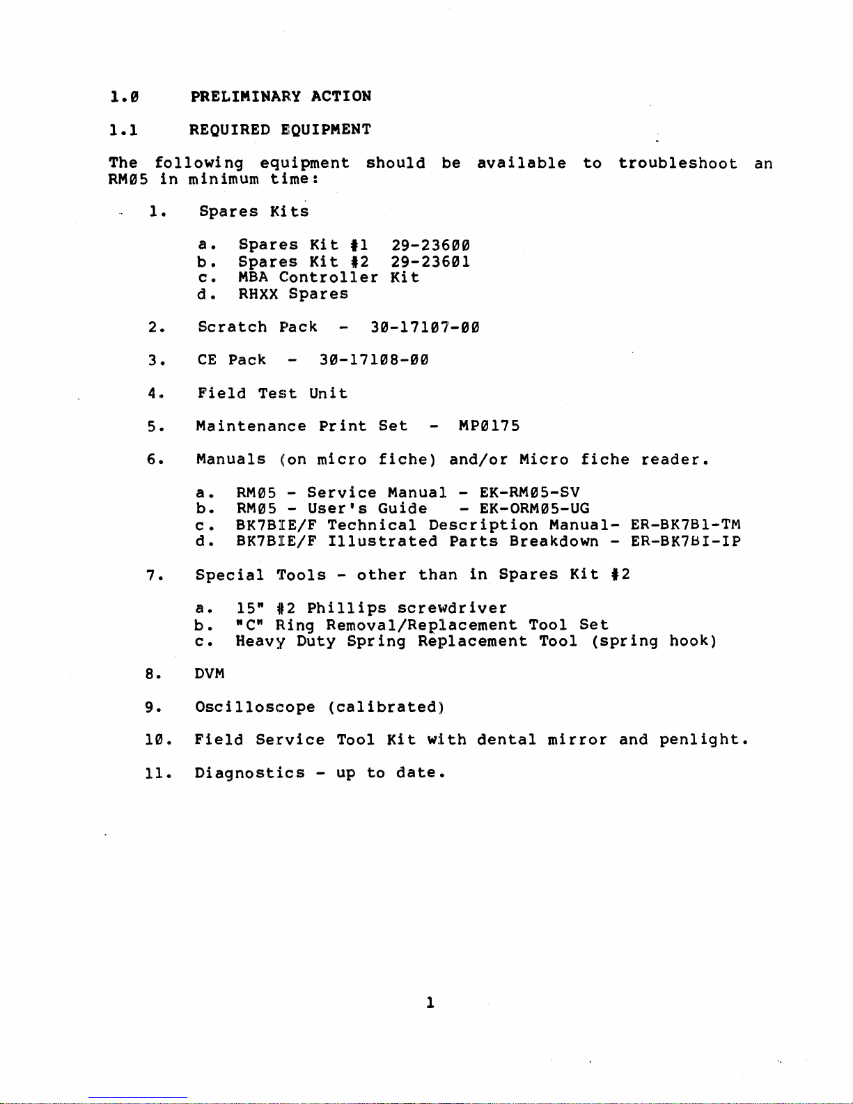
1.
Spares
a.
b.
c.
d.
2.
3.
4.
5.
6.
Scratch
CE
Field
Maintenance
Manuals
a.
b.
c.
d.
EQUIPMENT
equipment
time:
Ki
ts
Spares
Spares
MBA
RHXX
Kit
Kit
Controller
Spares
Pack
Pack
Test
30-17108-00
Unit
Print
(on
micro
RM05 -Service
RM05 -User's
BK7BIE/F
BK7BIE/F
Technical
Illustrated
should
11
12
29-23600
29-23601
Kit
30-17107-00
Set
fiche)
Manual
Guide
be
available
MP0175
and/or
- EK-RM05-SV
- EK-ORM05-UG
Description
Parts
Breakdown
Micro
Manual-
to
troubleshoot
fiche
-
an
reader.
ER-BK7B1-TM
ER-BK7BI-IP
7.
8.
9.
10.
11.
Special
a.
b.
c.
Tools
15"
*2
"C"
Ring
Heavy
DVM
Oscilloscope
Field
Service
Diagnostics
-
other
Phillips
than
screwdriver
Removal/Replacement
Duty
Spring
Replacement
(calibrated)
-
Tool
up
to
Kit
date.
with
in
Spares
dental
Tool
Tool
mirror
Kit
Set
(spring
,2
and
hook)
penlight.
1
Page 12
1.2
GETTING
STARTED
Customer
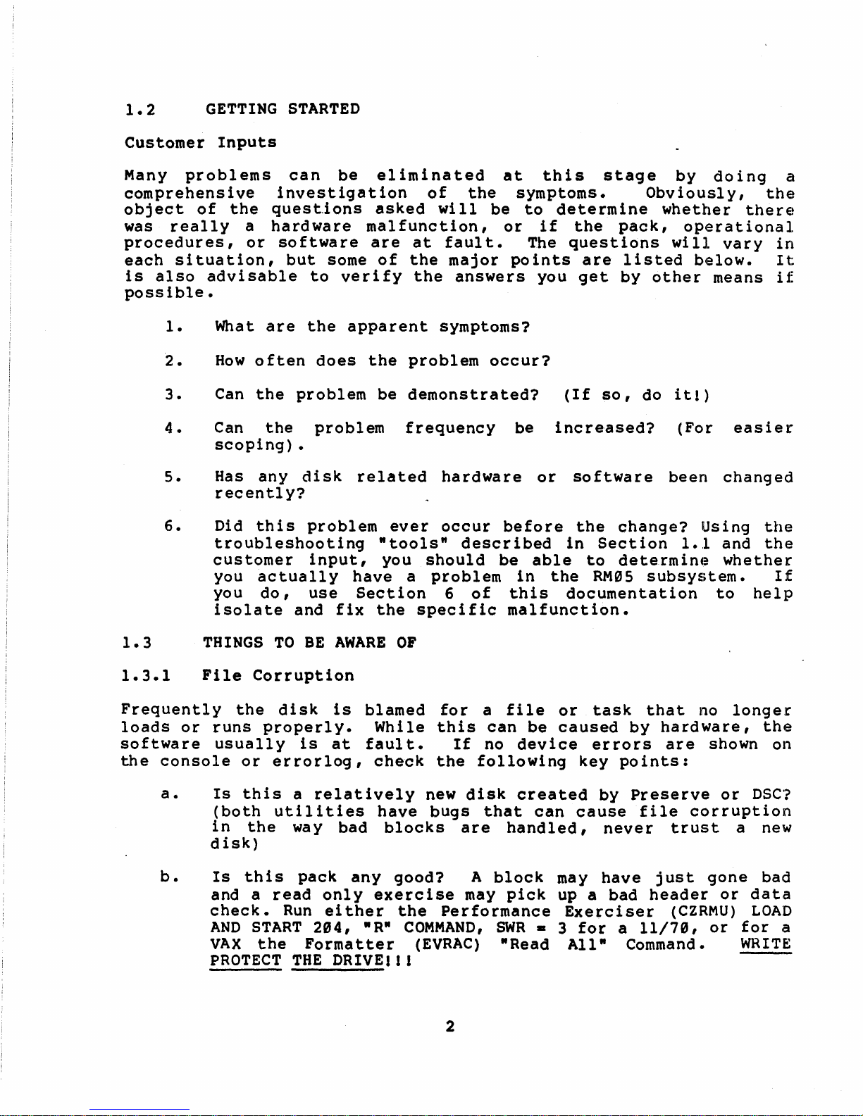
Many
Inputs
problems
comprehensive
object
was
of
really
the
procedures,
each
is
poss
situation,
also
ible.
1.
2.
3.
4.
advisable
What
How
Can
Can
scoping)
5.
Has
recently?
6.
Did
troubleshooting
customer
you
you
isolate
can
investigation
questions
a
hardware
or
software
but
to
are
the
often
the
problem
the
•
any
this
disk
problem
input,
actually
do,
use
and
be
asked
malfunction,
are
some
verify
apparent
does
the
problem
related
have
Section
fix
eliminated
of
will
at
fault.
of
the
major
the
answers
symptoms?
problem
be
demonstrated?
frequency
hardware
ever
occur
"tools"
you
should
a
problem
6
the
specific
at
the
symptoms.
be
to
or
The
points
occur?
be
before
described
be
able
in
of
this
malfunction.
this
stage
determine
if
the
pack,
questions
are
listed
you
get
(If
by
so,
increased?
or
software
the
change?
in
Section
to
determine
the
RM05
documentation
by
doing
Obviously,
whether
operational
will
vary
below.
other
do
means
itl)
(For
been
changed
Using
1.1
and
whether
subsystem.
to
a
the
there
in
It
if
easier
the
the
If
help
1.3
1.3.1
Frequently
loads
softwa
the
or
re
console
a.
b.
THINGS
File
Corruption
the
runs
properly.
usuall
or
Is
this
(both
in
the
disk)
Is
this
and a
check.
AND
START
VAX
the
PROTECT
TO
BE
AWARE
disk
y
is
is
at
errorlog,
a
relatively
utilities
way bad
pack
read
Run
only
either
204,
Formatter
THE
DRIVEl
blamed
While
faul
check
have
blocks
any
exercise
"R"
OF
for
this
t.
If
the
new
disk
bugs
are
good?
A
may
the
Performance
COMMAND,
(EVRAC)
I I
2
a
file
can
be
no
device
following
created
that
can
handled,
block
pick
SWR
- 3
"Read
or
task
caused
er
rors
key
points:
by
cause
never
may
have
up a bad
Exerciser
for
a
All"
Command.
that
by
hardware,
are
Preserve
file
corruption
trust
just
header
(CZRMU)
11/70,
no
longer
the
shown on
or
DSC?
a
new
gone
or
bad
data
LOAD
or
for
WRITE
a
Page 13

c.
Has
If
the
device
affected
errors
software
are
shown,
been
keep
changed
reading.
recently?
1.3.2
It
is
suddenly
the
for
backup
it
may
clean,
will
image
1.3.3
This
Bad
amazing
giving
bad
area
pack
maintenance
pack.
happen
ask
show
up
that
Environmental
is
a
electromagnetic
frequent
recently
for
heavy
shutdowns,
forklifts
have
the
only
problems,
changed
idle
(the
caused
way
specialist.
Packs
how
many
errors.
is
(header,
Look
during
the
customer
on
Errorlog
is
bad.
broad
radiation.
and
equipment
time
spark
problems.
to
be
inc1ud
for
the
Problems
field
so
verify
pay
on
etc.
coil),
sure
calls
The
result
symptoms
data,
ing
similarities
same
to
use
provided
that
that
attention
the
In
general
and
If
you
is
etc.).
bad
function
a
backup
it
covers
Power
same
have
to
consult
from
can
The
block
in
the
is
not
and
the
to
configuration
when
p~
keep
computer
reason
a
previously
vary
according
customer
mapping,
failure
and,
pack.
if
Obvious
Errorlog
temperature,
grounding
the
errors
(or
your
close
eyes
room
to
suspect
an
local
trusted
is
responsible
and
that
diagnostics
or
power
are
has
occur.
by),
open;
air
conditioners
environment,
environmental
to
keeping
indicate
bad
the
system
the
not
radios;
pack
where
a
run
areas
and
most
been
L60k
plant
1.3.4
A.C.
the
usually
major
(with
large
Bus
Unibus
Unibus
intermi
clue
a
scope,
enough
Troubleshooting
loading
1.3.5
Check
scope
Also
for
Power
all
for
check
supplies
ripple
the
Loading
loading
and
thE~
ttent,
is
to
hopefully),
to
Guide
more
detail.
Supplies
connections.
look
on
can
fast
cause
for
the
cause
devices
and
at
a
a
(on
microfiche-red
voltage
supplies;
virtually
see
diagnostics
working
and
gate
look
transition.
with
a
See
table
any
error
it
first.
usually
bus
for
with
dropouts
section)
a
DVM
primecause
3-1.
on
The
don'
everything
See
if
available.
of
any
device
symptoms
t
fail.
running
in
the
the
signals
Unibus
section
intermittents.
on
Then
on
are
The
AC
3
Page 14
2.g
TROUBLESHOOTING
AIDS
2.1
This
is
ERROR
one
maintenance.
operating
wIll.
Guide.
The
There
operation
Error
1.
2.
log
Was
What
of
semi-solid
system,
and
will
filter
day
LOG
of
the
If
you
the
procedure
should
printout
Be
certain
time
of
you're
terminated
available
generator.
errors
aid
in
there
out
is
common
environmental
most
valuable
don't
customer
should
be
a
of
the
that
the
using,
so
to
Otherwise,
you
are
determining:
actually
corrupted
between
hardware
know how
and
be
software
Error
NOTE
the
failure
and
that
that
the
the
looking
a
hardware
file
errors?
problems
problems.
and
least
to
DEC
entered
manual
Log.
error
is
error
current
errorlog
you
for.
type
used
run
it
software
in
on
file
on
the
logging
may
miss
error?
problems.
The
show
for
personnel
the
site
for
disk
file
report
bad
up
here,
tools
the
Site
deta:iling
the
is
is
the
This
blocks
for
system
particular
probably
Management
helps
and
as
do
time
most
the
you
3.
4.
5.
2.2
Look
Pa y
parts
from
SITE
up
spec
were
the
indicates
maintenance
alignments
situations
How
often
is
that
What
was
task
fa
i 1
ure?
involved?
What
pre
do
- d i a 9
exercise
have
to
MANAGEMENT
the
disk
i a 1
at
changed.
customer.
a
on
against
indicating
did
you
the
or
function
the
nos
harder.
work
history
ten t ion
problem
the
the
will
system
see
error
'a
doing
occur?
diagnostic
always
Are
tic
error
there
symptoms
i n d i
cat
On
system
ion
intermi
with.
GUIDE/LARS REPORTS
in
to
Correlate
It
is
wh
not
the
a t
LARS
ad j us
this
unusual
starting
device.
the
customer's
unreadable
Also,
packs.
Tells
failure.
at
the
time?
happening
or
indicate?
0 f
wh
ttents,
reports
tme
n t s
to
the
to
find
immediately
check
disk
you
Is
at
the
other
dev
This
at
to
this
or
we
may
maintenance
r e mad e
information
that
after
information
pack
usage
how
one
time
1
00
the
gives
likely
particular
of
ice
k
be
er
for,
all
c:lnd
you
error
the
on
log
ror
you
log.
wh
have
last
head
it
the
s
a
0 r
you
i c h
log
in
4
Page 15
2.3
CUSTOMER
DISK
PACK
USAGE
LOG
Customers
and
bad
a
potential
and
identify
2.4
These
great
diagnostics
help
release
time
them
found
and
in
in
2.5
In
many
tool.
ind
Consequently
ividua1
diagnostics
Reliability,
providing
At
the
time
are:
should
blocks.
pack
bad
keep
This
information
problem.
blocks
track
on
ON-LINE DIAGNOSTICS
are
generally
in
si
tuations
the
system.
if
the
easily.
the
customer's
OFF-LINE
cases,
di
agnostics
listed
system
DIAGNOSTICS
off-line
Unfortunately,
doesn't
The
diagnostic
software
diagnostics
it
is
and
are
all
Functional,
that
of
a
this
scratch
writing,
Verify
a
where
a
good
exactl
and
pack
of
pack
regular
quite
have
manual
idea
off-line
Formatter
is
the
current
usage,
is
quite
that
the
basis.
easy
the
customer
they
them,
operating
will
to
y
what
but
mounted
formatting,
useful
customer
to
are
you
won't
manuals
set.
be
be
very
they
the
can
on
the
diagnostics
when·
run
and
does
installed
be
the
only
familiar
test.
VAX
be
tested
backups,
looking
does
look
can
not
able
are
want
at
usually
sysgen
to
available
with
The
diagnostics;
run
on
drive(s).
for
the
for
for
be
put
the
11/70
line
RM05
of
to
PDPll
tZRML
CZRMM
CZRMN
CZRMO
DIAGNOSTICS
RM02/03/05
-
-
RM02/03/05
-
RM02/03/05
-
RM02/03/05
CZRMP -RM02/03/05
CZRMQ
CZRMR
CZRMS
CZRMT
CZRMU
-
RM02/03/05
-
RM02/03/05
-
RM02/03/0S
-
RM02/03/0S
-
RM02/03/05
CZRMV -RM02/03/0S
Formatter
Functional
Functional
Functional
Diskless
Diskless
Dual
Dual
Diagnostic
Diagnostic
Port
Port
Compatabi1ity
Performance
Extented
Drive
Test
Test
Test
Logic
Logic
Test
Exerciser
1
2
3
Test
Test
Test
Part
Part
Part
Part
1
2
1
2
5
Page 16
VAX
DIAGNOSTICS
EVRAA
EVRAC
EVRDA
EVRDB
There
are
The
Reliability
Disk
RM0X
RM0X
are
"buildup"
buildup
catastrophic
to
verify
starting
unknown
The
elements.
"breakdown"
intermittant
gets
the
errors.
cause
exercised
is
isolated.
Neither
of
diagnostics
system
work.
diagnostics
more
an
Section
detailed
indication
6.0.
Formatter
Diskless
Functional
many
techniques
and
approach
and a work
each
with
known good
problems
A
of
the
with
more
these
generally
However,
can
be
description
of
"breakdown".
is
ing
section,
approach
where
general
exerciser
error,
specific
approaches
overlap
if
an
effective
the
proper
in
using
commonly
system
in
an
equipment
to
diagnosticS'
basically
and
diagnostics
is
and
you
of
are
the
ones
diagnostics
used
is
effort
is
run
then
perfect
assume
aware
isolation
diagnostics
to
"bui1
to
and
is
the
the
until
that
of
method.
use
but
when
tup"
find
gradually
generally
system
to
get
suspect
the
in
all
the
in
under
the
using
the
an
other
1imi
You
this
the
most
failure
diagnostics
failure
adding
applied
works"
indication
sections
failing
cases,
parts
tations,
will
section
the
Error
common
the
but
are
section
as
the
of
the
the
find
and
Bit
is
by
to
it
of
a
2.5.1
Listed
As:
Special
Test
Description:
transfers
Suggested
working
Comments:
give
errors
CERHA
RH70
Controller
Requirements:
and some
Use:
RM05
This
is
if
When
available.
diagnostic
the
Functional
Tests
register-
a
media
Diagnostics
the
check.
controller
uses
is
bad.
Drive
RH70
using
Cylinder"
6
and
a
register
of
Scratch
disk
is
the
Pack.
drive
suspect
disk,
for
and
data
and a
could
Page 17
2.5.2
CZRML
Listed:
Special
Test
Description:
Suggested
Comments:
times
because
format.
to
isolate
To
access
at
2e4.
2.5.3
Listed
Special
as:
Requirements:
1.
2.
RMe2/03/05
Requirements:
Use:
Be
Pack
sure
possibly
A
pack
a
the
CZRMM,
with
read
Bad
CZRMN,
problem.
RM02/03/05
Formatted
Certain
areas
Formatter
A
Formats
formatting
the
scratch
the
a known
Sector
CZRMO
Functional
pack
for
on
working
disk
next
good
File
Parts
the
pack
RM05
and
and
media
time
format
utility
Test
2
must
subsystem
updates
updating
is
properly
the
system
is
routine,
Part
and
3.
be
and
the
Bad
the
Bad
may
invaluable
star.t
1,
2,
error
free.
scratch
Sector
Sector
formatted
not
be
when
the
& 3
pack.
File.
File.
at
all
able
to
trying
program
Test
tested
Description:
wi
read/write
Part
l:
register,
Part
header
check
2:
Performs
and
of
mid-transfer
Part
and wr i
implied
peak
3:
te
shift
Performs
seek.
multi-sectors
Suggested
1.
2.
Verify
Check
Comments:
if
not
halted
th
and
Tests
seek
data,
lis
seeks.
check
tests,
Use:
This
the
:Oiskless
servo
error
command,
wr i te
write
&
0's,
write
mul
Also
write
in
offset
logic
basic
program
properly
These
logic.
detect
and
and
format
and
ti
pIe
error
and
mode.
in
drive
with
diagnostics
Diagnostics.
log
offse~
read
check
of
write
sectors,
logic
read
RM
Adapter
read/write
will
disturb
a
Control
ic,
command.
of
header
multiple
check
(HCE,
each
not
test
error
header
and
data;
wr i
te
IVC),
track,
tested
and
the
"C".
It
abort
&
data,
sectors,
and
seek
header
RM
Adapter
also
log
data;
0's
wr i
write
read
by
functions.
tests
ic,
I
sector
write
error
and
te
current
and
write
Diskless
format
logic
the
look
and
lis,
check
1 &
of
dr
ahead
wr i te
write
logic,
write
wi
tests,
check
a
pack
not
ive
th
2.
7
Page 18
2.5.4
CZRMP,
CZRMQ
Listed
as:
Special
and
dr
ive
Test
the
Description:
RM
subsystem
performed
Suggested
Part
logic;
1:
command
seqencer.
Part
2:
sequencer;
Comments:
1.
2.
RM02/03/05
Requirements:
power
turned
up
on
the
RH70
Use:
Tests
To
basic
detect
decode;
Tests
ECC
The
The
as
additional
logic.
drive
multiple
the
drive
is
Diskless
Dr
ive
on.
Parts
to
the
and
1
and 2 combined,
drive
it
errors
handshaking;
port
used
for
sector
interface.
interface
is
reguest;
error
unit
transfer
Controller
interface.
assumed
and
faults
register
detect
selection.
logic
Part
cables
verify
No
to
work.
in
transfer;
attention
logic;
is
1 &
must
the
specific
the
RM
logic;
CRe
not
Part
be
plugged
operation
Adapter.
error
logic;
tested
2
tests
detect
control
as
in
of
are
data
well
2.5.5
Listed
Special
Test
also
Part
select
Suggested
log
lc.
CZRMR,
As:
RM02/03/05
Requirements:
1.
2.
3.
4.
Dual
Dual
Power
Operator
Description:
Part
1
tests
checks
2
tests
switch
Use:
Comments: Use
dual
port
operation.
CZRMS
Controller
Controller
off
drives
intervention
the
the
the
ability
timeout
duration
which
To
test
Performance
See
Dual
Option.
Test
not
release.
requires
the
Para.
Port
Logic
Cable
being
-
Part
to
seize
of
the
manual
basic
Exerciser
2.5.7
Test
PIN
70-10507-02.
tested.
2.
and
timeout
intervention.
operation
CZRMU
Part
release
release
of
to
1 &
the
test
Part
each
and
port
the
2
port.
the
select
dynamic.;
It
port
8
Page 19

2.5.6
CZRMT
Listed
Special
Test
following
between
As:
Require.en~s:
Description:
conditions
drives.
1.
2.
3.
4.
5.
Head
Positioner
Spindle/pack
Improper
Incorrect
Suggested
incompatibility
Comments:
should
drive
it
mechanical
2.5.7
can
be
(write
be
CZRMU
run
mis-alignments
Compatibility
.
mis-alignment
lateral
level
addressing
Use:
is
suspected
Funct:ional
first
current).
assumed
that
Formatted
This
which
interface
of
This
Test
to
eliminate
If
drive
or
scratch
diagnostic
most
commonly
mis-alignment
runout
write
current
of
read/write
program
between
Part
errors
3 and
then
incompatibility
tolerances.
pack.
is
designed
is
obviously
drives.
Extended
electrical
occur
cause
heads
problems
with
to
detect
incompatibility
used
Dr
ive
with
this
is
diagnostic;
attributed
Test
the
when
20
the
to
Listed
As:
Special
1.
2.
Test
Description~
purpose,
activity
are
words
Data
selected
transferred
Mode:
available
~ectors
per
efficient
Change
204.
Seek
parameter
Verification
exercises
transferred
RM02/03/05
Requirements:
Forma
tted
pack.
defaul t mode,
compare
Addresses
f~rrors.
of
operating
rate
on a RM05
by
the
per
Default
memory, up
command
run
tim1e:
"Passes"
Mode:
the
servo
per
command.
Performance
Packs
of
the
known bad
Performance
system
subsystem.
"Si
ze"
read
or
mode
to
8192
rather
than
Parameter
to
Selected
more
than
Exerciser
using
Extended
spots
tests
Dr
on
Exerciser
like
exerciser
It
parameter.
write
and
words.
order.
selects
single
This
sector
"Random" = 1 and
99
for
long
by
setting
Data
Mode
16,
ive
the
that
has
"Si
"Size",
mode
runs.
since
17,
Test,
pack.
is
a
maintains
two
ze"
basic
is
transfers
transfers.
the
Load
"Size"
only
and
will
give
good,
modes
the
number
depending
SWR
II:
and
to
256.
one
sector
21
out
data
general
a
high
that
multiple
For
most
000001.
start
This
of
of
on
at
is
9
Page 20
Suggested
Use:
1.
2.
3.
4.
5.
Comments:
1.
2.
2.5.8
CZRMV
As
a
To
surface
status
To
check
To
check
bad
final
block
overall
intermittents
information.
for
multiple
customer
file.
DRIVEI1! Load and
Dynamic
SWR
and
This
dual
=
is
port
00~001.
the
best
exerciser.
In
many
the
sections
cases
lower
level
faster
it
diagnsotics,
and more
subsystem
drive
packs
See
Start
testing
data
will
be
checkout.
and
give
interaction.
for
Para.
at
204,
-
bad
spots
9.8.
SWR= 3 and
use
transfer
faster
to
as
thoroughly.
additional
seek
test
isolate
they,
not
WRITE
logged
PROTECT
"R"
verification
and
problems
exercise
error
in
and
the
THE
Commana:-
mode
c)ver
all
with
isolated
Listed
as:
Special
formatted
Test
Description:
exercises
i
tse1
f.
the
drive
present,
Suggested
1.
2.
RM02/03/05
Requirements:
pack.
the
mechanical
The
the
sector/track
and
RM
mechanical
Test
and
and
the
the
Adapter
11
Test
Servo
default
operator.
Use:
When
When
up"
mechanics
RH/RM
approach)
Extended
Test
assumes
timing
is
an
21
system.
mode
of
Adapter
KW-11P
and
data
addressing
are
thoroughly
of
NOTE
extensive
is
a
stress
and
a
drive
tests
Drive
Clock
a
working
transfer
the
They
aust
are
have
Test
for
timing
RH
ability
and
posi
checked.
drive
is
positioning
test
are
be
of
not
selected
suspect.
shown no
and
tioning
verified.
test
the
R/W
run
by
er
tests,
RM
Adalpter and
of
t.he
portions
If
a }(W-IIP
in
ro-rs.
and a
drive
of
is
("build
3.
Checking
mechanical
performance
10
during
P.M.
Page 21
4.
In
conjunction
drive
interaction
with
Performance
problems.
Exerciser
to
isolate
s.
Comments:
1.
2.
3.
2.6
2.6.1
VAX
EVRAA
Doing
IC,
Timing
A
better
due
R
to
servo
for
tests
mechanical
run
Not a good
used
extensively.
Test
pattel~ns
data
for
Test
why
compare
Performance
28
test
DIAGNOSTICS
adjustments
test
1
run
time
RH/RM
16,
17,
when
last
21
is
or
2.
regularly
exerciser
and
operation.
Adapter
CAUTION
and
used
errors
Exerciser.
to
restore
not
by
check
21 a1
alone.
if
run
modifying
can
track
than
as
ters
This
the
pack
Always
the
pack
in
default
the
parameters,
mechanical
Performance
all
the
commands
data
causes
is
used
run
(that's
mode).
wear.
Exerciser
are
not
LC,
Listed
Special
(VMS)
Test
with
Description:
sections.
1.
2.
3.
As:
RK06/RK07/RP0X/RM0X/RL02/TUS8/RX02
Requirements:
a volume name
Qualification
support
Seek
Timing
mili-seconds,
(1,2,4,8,16,-
from
Media
sector
It
file.
goes
different
Test
on
doesn't
After
into
addresses
all
the
a mode
..
A
This
-
disk
from
512).
terminals,
-
Write
disk
report
all
formatted
o~
"Scratch"
program
verifies
drive
this
cylinder
and
(except
bad
the
sectors
wi
th
pack
contains
the
commands.
gives
If
there
the
Write
sectors
random
Reliability
which
or
"Diagnostic".
is
five
the
"0"
seek
drive
average
to
are
Checks
to
each
two
times
drives
5
home and bad
listed
have
been
in
written
patterns
not
RM03/05
be
seek
prime
"Mounted"
related
tested
times
cylinder
under
are
invalid.
patterns
sector
the
bad
,
files).
the
and random
will
in
test
every
sector
test
disk
11
Page 22
4.
Multi-Drive
random
data
concurrent
Test
to
mode.
-
tests
random
The
function
up
to
addresses
sequence
8
to
drives,
all
is:
transferring
drives
in
a
5.
Suggested
give
additional
problems.
Comments:
2.6.2
Listed
As:
Special
Test
File.
Description:
It
a.
c.
d.
e.
b.
Drive
Write
Write
Read
Data
data
compare
Conversation
and
as
drives
run
Seek,
simple
simultaneously
addresses
Use:
As
status
Run
Functional
EVRAC
Vax
Disk
Requirements:
is
broken
clear
random
Check
Mode
Read,
and
data
a
final
Formatter
Diagnostic
Formats
into
data
data
test
Wr i te,
and
EVRDB
six
-
allows
routines.
Wr i te
with
patterns.
overall
error
for
the
pack
areas.
the
Field
Selectable
Check
selectable
subsystem
information
worst
case
Supervisor
and
Engineer
can
checkout.
seek
reference
wr i tes
functions
be
or
for
testing.
the
to
design
run
up
random
to
disk
Also
intermittant
manuals.
Bad
Sector
such
8
to
1.
2.
INIT
-
This
assigns
determines
also
one
adjusts
track
multi-track
PACK
File
Bad
INIT
on
all
Sector
time.
a
channel,
if
transfers
transfers
sectors
File,
section
the
buffer
Format
is
builds
media
sizes.
and
of
the
are
are
the
pack
12
run
prior
a
is
a
done.
done.
writes
last
is
device
scratch
If
in
a
track.
formatted
to
all
dependent
pack
user
If
zero
mode (VMS),
in
entry
After
sections.
or
stand
reading
one
track
table,
not.
Bc3d
and
Init
only
alone,
Sector
the
at
It
a
Page 23
a.
This
unless
subsystem
is
missing
b.
This
new
packs
Sector
c.
The
written
section.
section
the
is
section
Files
new
until
user
OK
or
corrupted.
which
written.
Bad
CAUTIONS
should
verifies
and
has
do
the
to
not
Sector
the
end
be
never
Bad
used
have
File
of
the
Sector
to
the
is
the
be
disk
Pile
format
Verify
run
Bad
not
3.
4.
5.
6.
Suggested
Comments:
of
all
implications
FORMAT -Reads
formats
not
VERIFY -
reads
and
File
READ
data
that
precaution,
FLAG
File.
will
section
bad
sectors
with
Use:
This
one
read,
the
Reads
the
whole
entered
can
not
ALL
errors
may
-
Reads
found.
have
WRITE
BAD -Allows
CAUTION,
be
rewritten
is
great
show
the
Formatter.
Pack
formatting
program
and
and
track
program
and
in
the
be
read,
bad
can
inform
validates
at
validates
pack.
Bad
every
This
spots
PROTECT
for
if
this
with
for
up
only
rendor
a
time.
is
aborted.
Any
Sector
the
program
sector
is
THE
the
manual
section
a
updating
.under
and
customer
the
customer
the
If
the
bad
sectors
File.
on
ideal
that
are
DRIVEl
is
label
the
VMS
updating
Bad
Sector
the
Bad
Sector
is
aborted.
a
for
not
update
used
of
Bad
or
the
packs
of
File
Bad
Sector
.
File
found
If
the
pack
and
checking
flagged.
of
the
,
the
·Scratch".
Sector
diagnostics
Bad
Sector
useless.
your
intentions.
are
Bad
pr
user
Bad
home
File
and
File
and
flagged
Sector
ints
packs
As a
Sector
block
but
File.
Beware
then
is
then
the
This
when
not
2.6.3
Listed
Special
the
drive
Test
verify
It
does
module)
EVRDA
As:
RM03/05
Requirements:
power
Description:
the
operation
not
test
except
tur.ned
the
for
the
Diskless
The
on.
This
of
the
dr
ive
drive
Diagnostic
drive
Diagnostic
diagnostic
RM
Adapter
interface
select
13
interface
Supervisor.
consists
up
(RD
lines
must
to
and
that
be
of
the
sections
are
connected
80
tests
drive
used.
with
Which
interface.
of
the
CS
Page 24
Suggested
subsystem
Use:
To
independent
verify
of
the
the
drive.
operation
of.
the
RM03/05
disk
Comments:
diagnosing
2.6.4
Listed
EVRDB
As:
Special
Diagnostic
Test
which
Description:
can
line.
1.
2.
3.
This
disk
diagnostic
subsystem
RM03/05
Requirements:
Supervisor
be
selected
Data
verifies
of
Seek
which
Transfers
all
sector/tracks
Tests
verify
header
centerline
out
Timing
the
speed;
servo
Tests
minimum,
should
problems.
Functional
Test
Scratch
running.
This
diagnstic
via
-
Executes
a
section
logic.
and
This
seek,
command
section
recalibrate,
fUQctions.
electro-mechanical
-
This
section
average,
It
the
and
always
pack
contains
switch
all
data
also
error
contains
verifies
maximum
mounted
transfer
checks
detect
offset,
These
hardware.
be
used
four
in
the
the
positioning
test
the
pack
seek
fi
rst
and
test
Start
on
sections
Command
commands
addressability
logic.
and
r~eturn
throughly
rotational
times.
when
line.
and
tests
to
check
4.
Suggested
the
Diskless
read/write
Manual
Intervention
interventions;
address
Use:
plugs,
Verifies
Diagnostic
and
seeks.
pack
and
logic
and
Tests
acknowledge,
write
tests
not
lock
tested
basic
read
switch.
in
drive
Tests
in
the
all
preset,
RM
Adapter
functions
operator
operator
with
such
as
14
Page 25
3.0
POWER
ON
AND
MOTOR
SEQUENCE
NON-VDE
DRIVES
This
swi
section
tch
success
thorough
all
areas
1.
2.
3.
concerns
is
pressed,
of
troubleshooting
and
careful
is
in
order
Check
all
and
visual
for
circuit
CB6, CB7, and CB8.
Check
air
cleaning
If
rep 1 ace
loaded
Check
voltage
supply
of
and
filter
the
60
50
adj
Table
for
and
air
th
e f i 1 t e r •
at
cylinder
Hz Hz -
the
RM
and
if
the
usting
3-1.
blower
at
also
pressure
.15
.10
Adapter
ripple
voltage
it
from
the
any
the
or
or
back
the
dr
time
ive
motor
power on
observations.
power
breakers
motor
operation.
bottom
check
0.
less,
less,
is
Air
and
the
low,
p.r
replace
replace
drive
levels.
is
grossly
to
normal
CBl
problems
or
motor
-
CBl,
of
absolute
check
e s s
ute
power
Replace
level.
is
turned
comes up
is
A
general
problems.
CB2, CB3, CB4,
Inspect
the
drive
filter
for
rea
din
gsa
filter.
filter.
supplies
any
adjustable
out
of
tolerance
on,
to
s·peed.
dependent
inspection
the
for
air
air
leaks
r e
See
para.
the
primary
need
pressure.
wit
h he
for
proper
instead
start
The
upon
of
CBS,
of
and/or
ads
power
14.0.
3.
1
3.1.1
3.1.2
3.1.2.1
3.1.3
POWER
CBl
Trips
AlQl,
Blower
Time
Meter
AICl,
YEN,
YFN
CRI-CR4
Tl,
T2
eBI
CB2
Trips
AlQl,
T3
CB2
Short
K6,
YFN,
CB3
Trips
ON
PR,OBLEMS
AIQ5
Motor
AIC2 -
AIQ5
In
+29Y
K7,
1<8
YEN
CAUTION:
Distribution
Capacitors
charged
15
Page 26
3.1.3.1
When
CBl
AIQ2, AIQ3
Is
Turned
On
3.1.3.3
Immediately
Parking
Motor
Shortly
Noise
Belt
Tension
Shortly
Belt
Tension
Motor
CB4
Trips
Carriage
Head Load
A17
Servo
Po
K7
Voice
.22uf
Coil
Capacitor
CB4
After
B-rake
After
Is
Heard
After
Lock
Pin
Switch
we r Amp
Assembly
Motor
Motor
Bad
at
TB6
The
Start
Starts
Starts
Or
Misadjusted
Pins
Switch
Turning
Turning
7 & B
Is
Turned
Also
On
a
Squealing
3.1.5
3.1.6
_3.1.7
CBS
OR
5
Volt
Module
Servo
YFN
Control
CBS
or
CB7
Trips
Module
A2
Backplane
CBB
Trips
E"1
A2
Backplane
CBB
CB6
Trips
Regulator
Preamp
Panel
CB6
A10, A14,
short
short
(CBS
AlS,
only)
A16,
A17,
AlB
16
Page 27

~~.1.8
All
DC
Vol
CB2
Tripped
YEN
A1Q1
CBS
or
CB6
T3
+20Y
may be
Paragraph
tages
-
See
Missing
para
bad -interlock
loaded
3.1.2.1
At
3.1.2
down
~rest
Points
contacts
but
CB2
is
and
No
not
+20Y
tripped
see
3.1.9
:3
.1.10
3.1.11
3.1.12
3.2
+28V,
AC
-20V,
input
+20V,
A1C2 -CAUTION:
T2
-46V,
AC
+46V
input
I~ND
A1C1
T1
-46V,
+46V,
AND
A1QS
YFN
-9.7V
Ripple
YEN
YFN
DRIVE
missing
Too
for
for
MOTOR
High
all
DC
just
PROBLEMS
-16V
-9.7V,
Capacitor
-16V
Are
-16V
For
Just
voltages
Are
+9.7V
charged
All
Ei
Missing
One
except
Are
ther
Voltage
-16V
Either
High
or
All
Low
High
or
Low
3.2.1
3.2.2
3.2.2.1
Drive
A08
YFN
Start
Drive
+21Y
OJ(
YFN
A08
Motor
Starts
Switch
Motor Does
Missing
At
When
Not
Pin
CBl
Turn
3
17
Is
Turned
When
of
Start
AIQ2, AIQ3, AIQ4,
On
Switch
Is
Pressed
AND
9.7V
Is
Page 28
3.2.2.2
+28Y
Missing
YEN
CBE
T2
OK
At
Pin
3
of
A1Q2,
A1Q3,
A1Q4,
and
9.
7V
Is
3".2.2.3
3.2.2.4
3.2.3
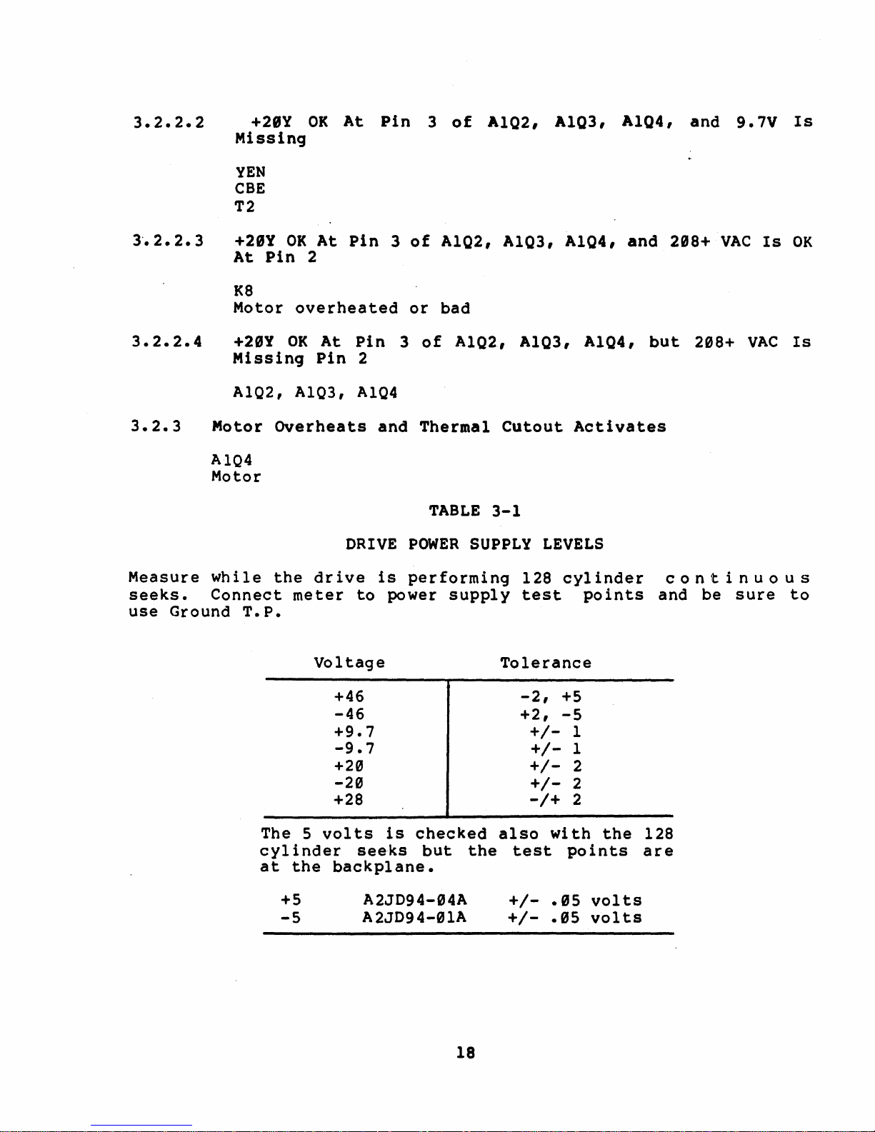
Measure
seeks.
use
Ground
+28Y
At
K8
OK
Pin
Motor
+29Y
OK
Missing
AIQ2, AIQ3,
Motor
Overheats
AIQ4
Motor
while
the
Connect
T.P.
At
Pin
2
overheated
At
Pin
Pin
2
AIQ4
DRIVE
drive
meter
to
3
of
or
3
of
and
Thermal
POWER
is
performing
power
A1Q2,
A1Q3, A1Q4,
bad
A1Q2, A1Q3,
Cutout
TABLE
3-1
SUPPLY
supply
LEVELS
128
test
A1Q4,
Activates
cylinder
points
and
but
con
and
298+
208+
tin
be
VAC
sure
Is
VAC
U 0 U 5
OK
Is
to
Voltage
+46
-46
+9.7
-9.7
+20
-20
+28
The 5 volts
cylinder
at
the
backplane.
+5
-5
is
checked
seeks
but
A2JD94-94A
A2JD94-01A
the
18
Tolerance
-2,
+5
+2,
-5
+/-
+/-
+/+/-
-/+
also
with
test
+/-
.95
+/-
.95
1
1
2
2
2
the
points
volts
volts
128
are
Page 29
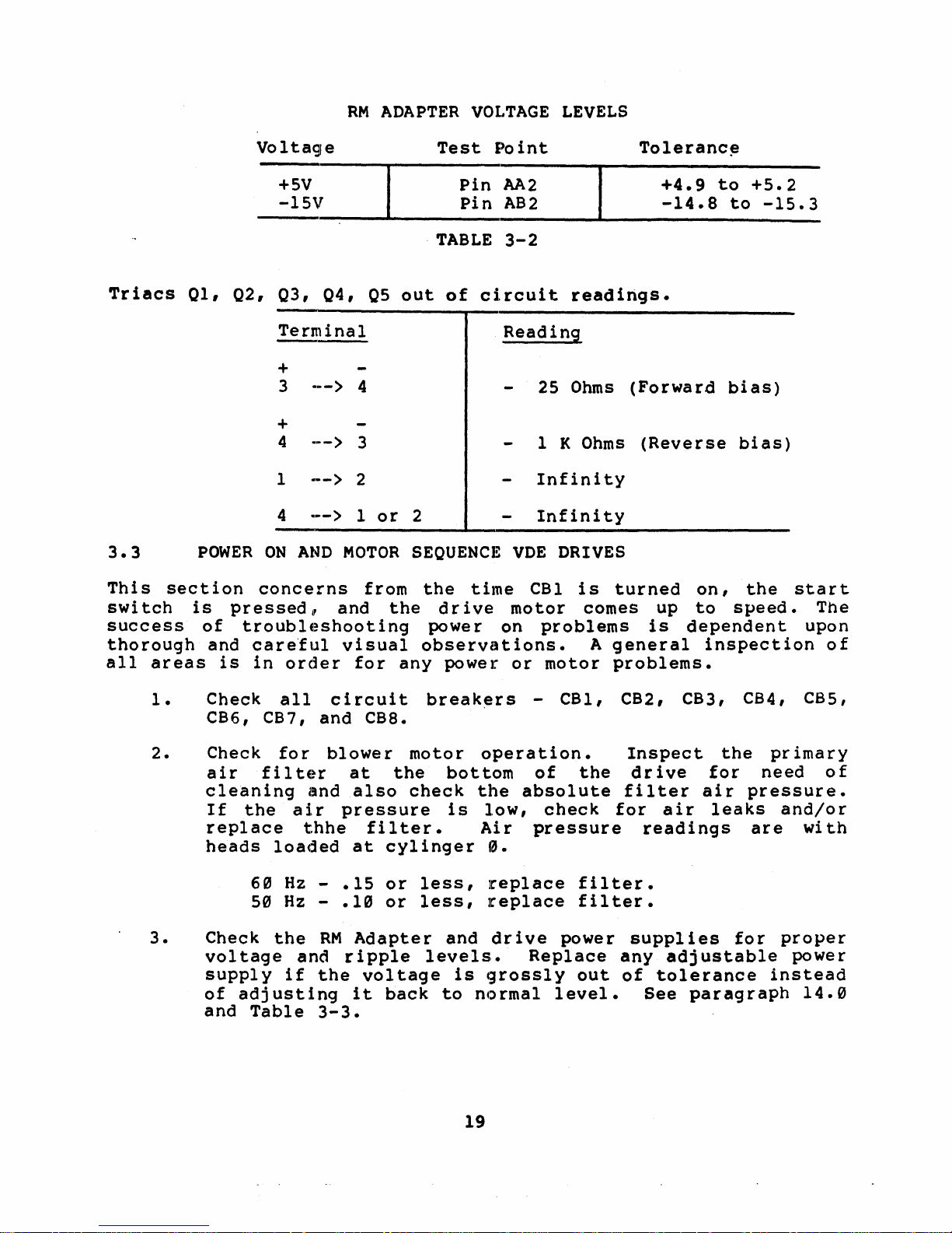
RM
ADAPTER
VOLTAGE
LEVELS
Triacs
3.3
This
swi
section
tch
success
thorough
all
areas
01,
02, 03,
POWER
is
pressed
of
and
is
Voltage
Test
+5V
-15V
TABLE
04,
05
out
of
Terminal
+
••
_>
3
+
4
1
4
ON
AND
concerns
troubl~:~shooting
careful
in
order
.•
_>
-->
..
-->
11
and
4
3
2
1
or
MOTOR
from
the
visual
for
any
2
SEOUENCE
the
dr
power on
observations.
power
Pin
Pin
circuit
time
ive
Point
AA2
AB2
3-2
Reading
25
1
Infinity
Infinity
VDE
CB1
motor
problems
or
motor
readirtgs.
Ohms
K
Ohms
DRIVES
is
turned
comes up
A
general
problems.
Toleranc~
+4.9
-14.8
(Forward
to
to
bias)
(Reverse
on,
to
speed.
is
dependent
inspection
+5.2
-15.3
bias)
the
start
The
upon
of
1.
2.
3.
Check
all
CB6, CB7,
Check
air
for
filter
cleaning
If
the
air
replace
heads
Check
loaded
6~
5~
the
Hz
Hz
voltage
supply
of
adjusting
and
if
Table
and
and
t.hhe
-
-
RM
and
the
3-3.
circuit
CB8.
blower
at
also
pressure
filter.
at
.15
.1~
Adapter
ripple
voltage
it
break~rs
motor
the
bottom
check
is
cylinger
or
less,
or
less,
and
levels.
back
to
operation.
the
low,
Air
0.
replace
replace
drive
is
grossly
normal
19
- CB1, CB2, CB3, CB4, CBS,
of
the
absolute
check
pressure
Inspect
drive
filter
for
readings
air
the
for
air
leaks
primary
need
pressure.
and/or
are
with
filter.
filter.
power
Replace
out
level.
supplies
any
of
tolerance
adjustable
See
for
instead
paragraph
proper
power
14.0
of
Page 30
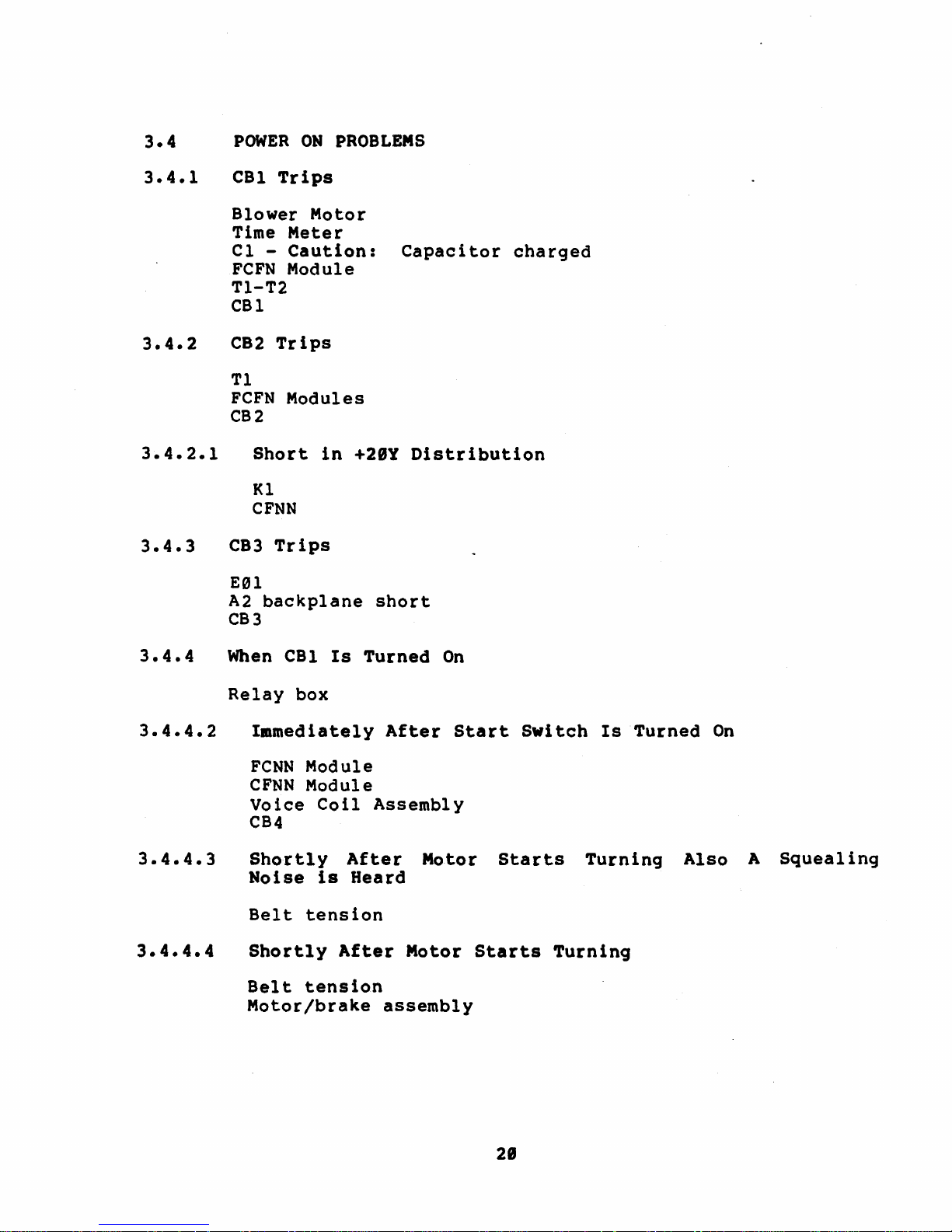
3.4
POWER
ON
PROBLEMS
3.4.1
3.4.2
3.4.3
CBl
Trips
Blower
Time
Motor
Meter
Cl -Caution:
FCFN
Module
TI-T2
CBl
C82
Trips
Tl
FeFN
Modules
CB2
Short
in
Kl
CFNN
C83
Trips
Eel
A2
backplane
CB3
+28Y
short
Capacitor
Distribution
charged
3.4.4.3
3.4.4.4
When
Relay
CBl
box
Immediately
FCNN
CFNN
Module
Module
Voice
CB4
Shortly
Noise
Belt
tension
Shortly
Belt
tension
Motor/brake
Is
Coil
After
is
After
Turned
After
Assembly
Heard
Motor
assembly
On
Start
Motor
Starts
Starts
Switch
Turning
Is
Turned
Turning
On
Also
A
Squeal
ing
28
Page 31

3.4.5
CBS
Trips
3.4.7
3.4.8
CFNN
module
Carriage
Voice
K2
CB6
5
volt
CCBN
CB6
CB8
coil
on
CFNN
or
module
or
Trips
Module
A2
backplane
All
DC
T2
FI-F8
CCBN
FCFN
module
module
Auxiliary
Breakers
Tl
CB2
locking
pin
assembly
module
CB7
Trips
regulator
module
CB7
Ale,
A14,
AlS,
short
Votalges
Missing
circuit
CB3, CB6, CB7,
A16,
and
CB8
~17,
no
+2ey
Al8
3.4.9
3.4.18
3.4.11
3.4.12
3.5
+28v,
T2
CCBN
-46v
T2
CCBN
-46v
CCBN
46"
AC
Ripple
CCBN
DRIVE
+29v,
mod
ul
e·
and
+46v
mocule
and
+46v
module
input
Too High
Module
MOTOR
-2ev,
Are
(CRl,
-9.7v,
Both
CR2, CRS, CRle)
Missing
(CRl,
CR2, CR9, CRIe)
for
Just
PROBLEMS
Are
High
one
Either
or
Low
Voltage
All
High
or
Low
21
Page 32

3.5.1
Drive
A98
module
Relay
Start
Motor
box
switch
Starts
When
CBl
is
Turned
On
3.5.2
3.5.2.1
3.5.2.2
3.5.2.3
3.5.2.4
3.6
The
drive
is
performing
power
point.
Drive
+21Y
CFNN
A98
+29Y
CCBN
CB6
+20Y
K3
Motor/brake
Motor
Relay
Motor/brake
DRIVE
power
supply
Refer
Motor· Does
is
OK
module
is
OK
module
or
CB7
is
OK
and
in
relay
Overheats
box
POWER
SUPPLY
supply
128
test
to
cyl
points
table
not
Turn
but
9.7v
But
9.7v
298
VAC
box
overheating
and
assembly
LEVELS
voltage
inder
3-3
continuous
and
be
for
When
is
Missing
is
Missing
is
or
Termal
levels
sure
voltage
Start
OK
bad
Cutout
are
seeks.
to
use
tolerances.
Switch
Activates
measured
ground
is
while
Connect
test
Pressed
the
drive
meter
to
The 5
cylinder
chassis
volts
is
continuous
backplane.
also
Refer
Voltage
+46
-46
+9.7
-9.7
+29
-29
+28
checked
seeks.
to
while
The
Table
Table
22
the
test
3-4.
3-3
drive
points
Tolerance
-2v,
+2v,
+Sv
+5v
+lv
+lv
+2v
+2v
+2v
is
perfolC'ming 128
are
on
the
logic
Page 33

Table
3-4
3.7
The
peak
measure
jack
and
Refer
3.8
The
RM
if
out
and
tolerance.
PEAK
to
the
voltage
to
Table
RM
adapter
of
tolerance.
Voltage
+5v
-5v
TO
PEAK
peak
ripple
ripple
3-5
ADAPTER
voltage
RIPPLE
should
peak
test
for
jacks
peak
Voltage
+46
-46
+20
-20
+28
VOLTAGE
levels
Refer
Test
to
peak
LEVELS
Point
A2JD94-04A
A2JD94-0lA
be
checked
ripple
on
the
to
peak
Table
ripple
3-5
should
to
Table
voltage
power
Ripple
4.5v
4.5v
1.0v
1.0v
1.0v
also
3-6
Tolerance
+.05
+.05
using
supply
voltage.
be
checked,
for
voltage,
volts
volts
an
oscilloscope
between
control
the
and
test
to
ground
panel.
adjusted
points,
Voltage
+Sv
-lSv
Table
Test
Pin
Pin
Point
AA2
AB2
3-6
Tolerance
+4.9v
-14.8v
to
to
+5.2v
-l5.3v
23
Page 34

4.9
HEAD
LOAD
SEQUENCE
PROBLEMS
This
section
operation
speed.
braking.
they
will
4.1
4.
2
4.3
after
It
also
If
the
be
called
HEADS
DO
REVERSE
concerns
the
start
includes
possible
out.
NOT
CURRENT
problems
switch
causes
LOAD
the
AFTER
NON-VDE
Head Load Swi
Servo
Power
tch
Amp
K7
Voice
HEADS
REVERSE
Coil
DO
IS
NOT
OK,
LOAD
FOR
AFTER
BOTH
A20, A07, A12, A08, Al7
Servo
CARRIAGE
HEADS
Power
HITS
STAY
Amp
FORWARD
OUT
ON
STOP,
PACK,
during
is
pressed
head
are
unload
different
UP
UP
TO
NON-VDE
CB4
FOR
BOTH
TO
SPEED
SPEED
AND
TRIPS,
NON-VDE
the
actual
and
the
sequence
for
TIME
motor
and
NON-VDE
OUT
VDE
Head Load Swi
Servo
Voice
VDE
Power
Coil
TIME
DRIVES
FAULT
AND
OUT
LIGHT
VDE
head
is
spindle
and
AND
tc
h
Amp
AND
ON,
DRIVES
load
up
to
VDE
NO
HOLD
AND
4.4
4.5
4.6
*
A06,
Servo
Al9,
Power
CARRIAGE
AND
HEADS
A2((J
Servo
HEADS
(INNER
A((J6,
Servo
HEADS
NON-VDE
Servo
Servo
Power
LOAD,
GUARD
Al9,
Power
LOAD,
AND
Preamp *
Head *
Disconnect
Then Check
25B.
OK,
it
If
is
A20
Amp
HITS
FORWARD
RETRACT,
Amp
HESITATES,
BAND),
A20
Amp
BUT
VDE
A3TBI-I
for
not
OK
one
of
FOR
FOR
THEN
DRIVES
(yellow
.3
-1.5vpp
it
is
the
STOP,
BOTH
AND
THEN
BOTH
FAULT
NON-VDE
NON-VDE
UNLOAD,
wire)
servo
the
Servo
following.
LIGHT
AND
CREEP
FAULT
and
data
Preamp
TO
AND
LIGHT
load
at
or
ON,
VDE
THE
VDE
A18
THEN
DRIVES
FORWARD
DRIVES
ON,
heads
Pins
Servo
CB4
TRIPS
EOT
FOR
BOTH
manually.
23B
and
Head.
If
A18,
Al9,
A2((J
24
Page 35

4.7
RTZ
IS
NON
FUNCTIONAL,
POR
BOTH
NON-VDE
AND
VDE
DRIVES
4.8
4.9
4.19
4.11
A96, A07,
UNABLE
VDE
A96,
UNABLE
(8),
TO
DRIVES
A12,
TO
FOR
A06, A12,
BEADS
LIGHT
DO
OFF,
A08, A07,
Start
Switch
YFN
DRIVE
Open
MOTOn
thermal
K8
CR1-CR4
Bad
connection
Al9,
,sEEK
A20,
FORCE
BOTH
A20
NOT
PACK
A20,
BRAKE
A29, A02,
TO
CLYINDER
A02
A
NON-VDE
,A02
UNLOAD
SPINNING,
A17
INOPERATIVE,
resistor
to
motor
SEEK
AND
WHEN
in
A12
1466
ERROR
VDE
DRIVES
START
POR
SWITCH
BOTH
NON-VDE
CB3
connector
(8),
WITH
P/J7
POR
FTU
TO
IS
TURNED
NON-VDE
DRIVE
BOTH
CYLINDER
AND
ONLY
NON-VDE
OFF,
VDE
START
DRIVES
AND
1467
4.12
DRIVE
FeFN
CCBN
Bad
Connection
Bad
Connection
MOTOR
ModulE~
BRAKE
Module
INOPERATJrVE,
to
Brake
to
Motor
P8/J8
P7/J7
VDE
DRIVE
ONLY
2S
Page 36

5.0
Oi
sk
dr
amplitude
abnormal
loading,
rected
immediately
failures
base
quent
corruption
power
POWER
ives
are
analog
variations
vol
tage
from
supply
AND
POWER
susceptable
signals
in
spikes,
before
abnormal
with
no
related
FAIL
used
the
input
excessive
any
line
apparent
failures.
PROBLEMS/RM
to
power
in
problems
the
power
surges
intermittent
power
have
error
ADAPTER
due
Read/Write
such
or
as
sags
failures
symptoms
bit
indications
to
the
circuit.ry.
mismatched
should
occur.
of
long
low
be
Typical
term
and
level
Any
phase
cor-
data
fre'-
5.1
This
signal
respective
the
CPU.
Massfail
down
of
evident
MASSBUS
RH7~
RH78~
-
Any
- Check
supply
5.2
The
AC
RM
Unsafe,
MASSFAIL
is
RH
controller
Under
signal
the
if
or
in
normal
is
disk
there
the
Unibus
the
(#5).
In
order
function
older
must
out.
LO -UNSAFE,
Adapter
if
low
AC
sent
to
operation
received.
subsystem.
is
a
RM
Adapter.
device
+5
volt
to
properly,
8780
be
configured
BIT 14
-15
is
detected
volt
all
to
drives
indicate
problem
that
generates
DC
have
MASSBUS
OF
regulator
for
the
system
Massfail
Non
Exlstant
with
Lo
signal
NOTE
the
the
terminator
correctly:
RMERl
the
on
the
a power
provides
the
Massfail
AC
Lo
at
Massfail
jumpers
asserts
RM
Adapter
MASSBUS
problem
will
Drive
could
J3
signal
on
modules
WI
in,
AC
power
an
errors
of
the
the
W2
Lo,
power
from
in
fail
orderly
signal
be
at
7l~~
which
source.
the
will
on
fault.
their
RH
as
the
shut
the
power
sets
or
be
If
the
and
proble.
supply.
5.3
DC
indication.
examined
Lo
DC
does
LO
but
not
All
the
the
flag
the
RH
fault
lite
unsafe
is
wi
an
RM
Adapter
registers
bit
th
error
are
NOTE
is
not
the
bit
registers
OK
26
on
is
RM
except
in
set,
adapter
but,
the
then
does
are
for
drive
the
power
give
read
CS1.
as
an
ones
obvious
when
Page 37

6.g
ERROR
BITS -CONTROL
AND
ERROR
REGISTERS
This
to
section
use
would
When
trying
status
defective
first
to
start
8
scope
and
error
it
is
STATUS
1.
2.
3.
Multiple
parity
RMER2
bit
all
in
bits
for
trouble-·shooting.
cause
logic
components
and
easiest
you
and
logic
obvious.
AND
ERROR
Drive
M7686 -
A0l,
bits
error
is
set;
RMAS;
when
gives
the
er~or
to
locate
is
functioning
off
in
meter
should
LOGIC
Interface
drive
A02,
will
occurred.
bit
bit
isolating
the
error
and/or
a
are
to
replace.
the
~,ill
be
be,
INCLUDES
status,
A17 -
be
set
15
(ATA)
15 (SC)
definition
symptom.
problem,
properly.
listed
right
needed
for
Cables
drive
when
Bit
03 (PAR)
and
and
an
error
Also
it
in
These
area
to
most
- A & B
drive
status,
an
error
bit
bit
14
condition.
with
given
is
assumed
The
order
component
but
test
isolate
cases,
errors
drive
occurs.
of
RMERI
14
(ERR)
(TRE)
suggested
are
the
list
of
most
equipment
further.
considered
errors
and
of
of
RMCSI.
components
that
of
the
possible
likely
listings
EXAMPLE:
bit
RMDS;
corresponding
~iagnostics
which
error
to
are
such
The
last
status
and
fail
given
as
unless
A
03 (DPE)
Be
aware
of
of
Table
be
used
when
RM
ADAPTER
6-1
gives
to
relate
troubleshooting
ERROR
ILF
ILR
RMR
PAR
FER & HCRC
FER
WCF
ECH
&
DCK
HCE
related
the
Error
with
FTU
the
NA
NA
NA
NA
Address
NA
NA
Address
Address
and/or
errors
Log
FTU.
Table
FTU
to
or
Diagnostic
6-1
ERROR
and/or
and/or
-
Address
subsystem
Read
Read
because
because
errors.
printouts
of
head
misselect
of
misposition
This
to
can
errors
SKI
27
Page 38

RM
ADAPTER
ERROR
Table
FTU
6-1
(Cont)
ERROR
HCE & HCRC
HCRC
AOE
IAE
WLE
DTE
OPI
UNS & DVC
DCK
DPE
DVC
LBC
Address
Address
NA
NA
Fault
Read
after
and/or
Sector
Fault
Address
NA
Fault
Address
and/or
and/or
Read
Count
and/or
and/or
write
or
Read
Read
Address
no
Read
Read
error
FTU
error,
Run
Address
hangs
6.1
6.1.1
LSC
IVC
OPE
SKI
BSE & HCRC
CONTROL
Control
13
BIT
BIT
MCPE
RM
RH.
Bus
17
indicates
while
Reg
ister
It
REGISTER
Register
MASSBUS
read
that
is
the
NA
No
Plug
No
SKI
Address
CONTROL
that
ing
a
an
does
Attention
Uni t Ready
No.
doesn't
Un
it
Select
Address
and/or
PARITY
parity
RM
reg
not
error
ister
use
Register.
equal
Read
ERROR
occurred
to
the
par i ty
switches
(MCPE)
RH.
on
transfer
on
ThelC'e
- :RH70
-
RH780
the
Control
to
is
one
the
28
Page 39

THINGS
TO
KNOW
WHEN
TROUBLESHOOTING
MCPE
ERRORS
1.
The number
on
installations)
following:
A.
Check
M5904's'
flat
M5904.
B. Check
(Zero
on
the
C.
Visually
cables
wear.
D.
A
visual
is
necessary.
E.
Inspect
broken
tors
give
which
intermittant
one
the
RH70
cable
This
the
Insertion
bottom
inspect
for
inspection
the
or
cracked
have
cause
of
seems
connections
(Berg
connector).
sometimes
effects
connections
Force)
rear
of
the
damage,
kinks,
massbus
resistor
broken
parity
MASSBUS
tC)
be
in
of
shorts
Data
of
Bits
BC06R
connector
the
cabinet.
cable
breaks
of
all
terminator
or
cracked
errors.
Parity
the
the
BC06R
The
against
00,
located
insulation
and
ZIF
connector
for
packs.
Errors
cabling.
cables
drain
the
06,
or
cables
other
bent
MASSBUS
resistor
(especially
o
Check
wire
etch
12.
at
the
on
the
on
the
signs
mating
pins,
termina-
packs
at
on
on
panel
BC06R
pins
will
the
the
the
the
ZIF
of
and
2.
3.
To
isolate
features
A. The
that
maintenance
disable
B.
In
multiple
move
Remember,
times"
otherwise,
non-e,cistant
isolate.
C.
If
an
drives
drives
MASSBUS
drives
MASSBUS
specification
the
feet
must
flat
and
be
160
llsed
calculate
Manual.
solid
will
MCPE
help
switches
all
transceivers
the
RM05
terminator
the
and
at
installations,
MASSBUS
least
erroneous
drives.
eight
will
will
load
will
Cable
drive
operate
fail
of
see
Length
clearly
intermittently.
the
the
states
(BC06R-XX) and
the
feet,
for
maximum
respectively.
mixed
problems,
out.
on
in
order
must
one
parity
Use
system
properly,
last
load
as
Specification
that
round
flat
length.
on
the
that
to
be
dr
ive
errors
the
is
MASSBUS
in
dr
ives.
a
terminator.
the
(BC06S-SS)
A
and
See
round
the
there
M5922
bus,
break
isolate
terminated
enabled
use,
but
This
The
maximum
linear
cable
MASSBUS
are
and
for
the
the
on
will
TDR
the
the
is
several
M5923
that
MASSBUS
problem.
the
occur
Tester
first
last
due
first
The
MASSBUS
lengths
cables
are
interpolation
systems
TDR
will
drive.
at
bus,
four
four
to
four
120
Tester
and
all
to
to
the
for
to
29
Page 40

Diagnostics
11/70
CZRMP
CZRMQ
CZRMU
Drive
Not
Drive
RH70
~es
M5994
M8152
TRE
If
for
no
RH70
M81S1
MS904
6.1.2
Diskless
Diskless
2
Performance
Caused
is
not
set
reason.
(B)
Control
Exerciser
and
Register
no
errors
VAX
EVRDA
EVRAA
RM
Diskless
Reliability
Adapter
Terminator
Cables
M5922,
M5923
Grounds
M7686
RH780
M8278
M9041
are
present
RH780
M8278
or
Jumpers
attention
or
(Wl
and
is
W2)
set
6.1.3
BIT 14
TRE
indicates
controller
OR-ing
error
TRANSFER
or
of
DLT,
bit
in
the
one
registers.
Control
Register
BIT 15 SPECIAL
SC
bit
of
or
for
flag
indicates
being
a
normal
the
completion
either
for
something
that
set
by
condition
a
normal
Diagnostics
an
PE,
(TRE)
error
Drive.
NED,
ERROR
that
Disk
WCE,
or a combination
CONDITION
an
error
MCPE.
(SC)
Also
such
of
a
positioning
or
abnormal
happened.
Depending
condition,
occurred
This
NEM,
of
condition
attention
as
the
condition,
in
error
PGE,
all
condition
MXF,
three
exists
will
drive
cloming
command.
on
all
including
either
MDPE
drive
thru
set
SC
SC
it
the
the
is
the
because
on
could
is
just
DECXll
the
or
error
TRE
line,
set
error
RH
an
a
31
Page 41

DRIVE
Normally
thru
RM
the
ADAPTER
Check
problem
M7686
MS922,
Check
section
If
no
errors
RH70
M81S1
M81S0
If
TRE
for
no
or
abnormally
attention
for
error
if
attention
MS923
Diagnostic
Drive
the
of
error
this
are
is
not
reason.
bit.
bi
ts.
registers
manual.
I
present
set.
and
is
the
Check
If
set.
no
drive
none
and
errors
going
for
set
refer
RH780
M8278
are
error
these
All
RM
Adapter
present
on
or
conditions.
modules
including
to
the
offline.
DECXll
specific
or
attention
may
will
cause
error
set
is
SC
the
bit
set
RH70
M81S1
MS904
6.2
6.2.1
THINGS
1.
(B)
STATUS
Status
BIT.88
BIT 88
An
MOPE
synchronous
command.
Write
Check
anywhere
TO
KNOW
The number
on
installations)
following:
REGISTER
Register
MASSBUS
indicates
(data)
(Read,
Header
:from
WHEN
TROUBLESHOOTING
one
the
cause
DATA
a
bus
Read
and
RM
Adapter
seems
RH780
M8278
PARITY
parity
lines
Header
Data).
of
MASSBUS
to
ERROR
error
and
to
MDPE
be
in
(MDPE)
during
Data,
The
the
error
RH.
ERRORS
Parity
the
was
a
Errors
cabling.
-
-
detected
read
Wr i te
could
(especially
RH70
RH780
on
type
Check
be
caused
Check
the
data
or
the
31
Page 42

A. Check
M5904's
flat
M5904.
the
RH70
cable
This
connections
(Berg
connector).
sometimes
effects
of
shorts
Data
the
Bits
BC06R
The
against
00,
drain
the
06,
cables
wire
etch
or
12.
at
on
on
the
the
the
2.
B. Check
(Zero
on
the
C.
Visually
cables
wear.
D.
A
visual
E.
Inspect
broken
terninators
packs
To
isolate
features
A. The
disable
B.
In
multiple
move
Remember,
times,
otherwise,
non-existent
Tester.
the
connections
Insertion
bottom
inspect
for
damage,
inspection
the
MASSBUS
or
which
will
give
solid
that
will
maintenance
all
transceivers
RM05
the
terminator
the
and
at
erroneous
Force)
rear
of
the
kinks,
cracked
have
intermittent
MOPE
help
switches
installations,
MASSBUS
least
drives.
of
connector
the
cable
of
all
terminator
resistor
broken
problems,
out.
on
on
in
order
must
one
parity
Also
BC06R
cabinet.
insulation
breaks
ZIF
connector
parity
the
that
to
be
dr
ive
.errors
use
cables
located
and
other
for
packs.
or
cracked
errors.
there
M5922
bus,
break
isolate
terminated
enabled
the
at
on
on
mating
bent
are
and
M5923
for
that
the
MASSBUS
the
on
will
MASSBUS
the
the
panel
the
BC06R
signs
pins.
p:lns,
MASSBUS
resistor
several
drive.
problem.
at
the
occur
ZIF
of
and
will
and
all
bus,
to
TOR
3.
c.
If
an
drives
drives
MASSBUS
see
the
MASSBUS
specification
the
feet
must
flat
and
be
used
calculate
Manual.
eight
drive
will
will
load
load
Cable
fail
of
as
Length
clearly
(BC06R-XX)
160
feet,
for
the
maximum
system
operate
intermittently.
the
last
a
terminator.
Specification
states
and
round
respectively.
mixed
flat
length.
32
is
properly,
drives.
that
(BC06S-XX)
and
See
use,
in
the
A
linear
round
the
the
but
the
This
The
first
maximum
cables
cable
MASSBUS
first
last
is
due
to
four
The
MASSBUS
lengths
are
interpolation
systems
TDR
Tester
four
four
the
will
for
120
to
Page 43

Diagnostics
11/70
CZRMQ
CZRMN
CZRMO
CZRMU
Drive
DeL
~les
M7685
M5922,
RH70
CaE'res
M5904
M8l50
6.2.2
Diskless
2
Functional
Functional
Performance
M5923
Status
Register
BIT 99
MXF
indicates
transfer
what
happens
condition.
transfer
respond
MASSBUS.
2,
3
Exerciser
MISSED
that
command wi
is
The
command
to
it
by
TRANSFER
the
thin
three
first
and
one
the
sending
VAX
!VfiDA
EVRDB
EVRAA
Diskless
Functional
Reliability
RH780
MS·277
M904l
(MXF)
drive
650
condi
did
msec
tions
being
RM
Adapter
"Occupied"
for
that
not
may
the
did
back
respond
an
RH70.
cause
RH
not
to
to
Basicall
this
decoded
decode
the
RH
a
a
via
data
error
Data
it
or
the
y
The
the
sector
best
other
get
The
first
drives
because
four
the
packs.
addition
Diagnostics
11/70
CZRMQ
CZRMN
CZRMO
CZRMU
Diskless
Functional
Functional
Performance
second
MASSBUJS
wi
th
thing
Diagnostics
MXF
thi
errors
rd
four
reason
drives
will
of
the
drives
MASSBUS
This
to a missed
2
2
3
reason
was
the
to
not
word
do
with
fail
MASSBUS
will
see
terminator
will
is
that
"EBL"
rece i ved
counter
is
scope
errors
other
is
that
will
operate
for
are
error
in
intermittently.
load
the
of
load
for
give
you
transfer
VAX
!V'R"DA
EVRDB
EVRAA
33
from
in
the
cleared
"Occupied"
present.
conditions.
an
eight
properly,
The
the
last
as
a
terminator.
broken
intermittent
error.
Diskless
Functional
Reliability
the
RH
(run
or
RM
at
the
cleared).
or
It
is
dr
ive
but
reason
drives.
cracked
parity
Adapter
end
"EBL"
possible
system,
the
last
being
The
Also
errors
via
of
the
The
if
the
four
first
check
resistor
no
to
is
in
Page 44

Drive
Not
Drive
Caused
RM
Adapter
ItlXSSBOS
Cable
MS922, MS923
M7686
M7684
RH70
CaDre
MS604-B
or
M81S1
6.2.3
Status
Bit
PGE
to
performing
tr
maintenance
the
transfer
Diagnostics
11/70
CZRMQ
CZRMN
CZRMO
Diskless
Functional
Functional
Drive
Not a Drive
C
18
indicates
initiate
ied
RH7S0
Problem
Register
PROGRAM
one.
to
load,
mode
an
command.
2
2
3
for
a
data
during
attempt
ERROR
the
In
addition
MAP,
RH780
M8278
M8277
M9041
(PGE)
RH70 & RH7S0
transfer
VAR,
a
data
to
VAX
EVRDA
EVRDB
EVRAA
operation
for
or
transfer
initiate
Diskless
Functional
Reliability
that
the
byte
software
while
RH780,
counter,
command.
a
unacceptable
attempted
currently
the
program
or
Also
set
for
data
RH70
MSISl
6.2.4
This
1.
2.
3.
Status
Bit
NEM
and
register
problem
Software
Defective
Hardware
detection
Register
11
sets
the
can
NON
EXISTANT
when
the
memory
is
non-existent.
be
caused
Memory
problem
logic.
MEMORY
controller
address
by:
Stack
with
RH780
M8278
M8276
specified
the
34
(NEM)
is
Bus
performing
in
Address
a
DMA
the
Bus
Register
transfer
address
or
error
Page 45

Diagnostics
11/7~
DECEX
RH70
MS151
MS152
6.2.5
1.
2.
3.
11
Status
BIT
12
BIT 18
NED
in
Sets
a
Essentially
"Transfer"
transmi
could
Mass
Drives
M5923.
Drive
Register
NON
when a
drive
ttfed
cause
Fail
are
select
EXISTENT
which
what
on
the
over
NED.
is
asserted.
disabled
lines
DRIVE
program
does
happens
MASSBUS
the
MASSBUS
by
or
VAX
RH780
MS276
M8275
reads
not
is
See
the
Logic
(NED)
or
exist
that
1.5
from
para.
enable
is
defective.
writes
the
Usee
the
5.1
switch
or
RH
a
is
did
after
RH.
RH70
RH780
drive
register
.powered
not
received
"Demand" was
Several
on
the
M5922
down.
things
or
4.
5.
Diagnostics
11/70
CZRMP
Diskless
Drive
Power
on?
RH70
ra"6les
M5904
(C)
MS151
MS153
MASSBUS
RM
Adapter,
DEV
Selected
1
failure
or
of
"Demand"
MASSBUS
neg~ted
and
cabling.
in
RM
Adapter.
VAX
ERVDA
RM
~
Diskless
Adapter
Adapter
MASSBUS
M7686
M5922, M5923
RH780
A8278
M8276
or
not
cables
"Transfer"
powered
in
on
the
RH,
35
Page 46

Diagnostics
DECXll
Drive
Not
a
Drive
RH7e
M8T52
M81Sl
Status
BIT
13
PE
indicates
the
controller
command.
Problem
Register
PARITY
a
ERROR
parity
is
(PE)
error
performing
from
memory
a
Write
is
detect~~d
or
Writ.e-Check
while
6.2.7
Areas
Status
BIT
BIT
weE
operation
corresponding
The
s
tat
with
inc
If
changed
Data
that
1.
MASSBUS
parity
2.
Data
Register
14
"9
sets
WRITE
&
1"
when
and
thing
us
weE
0 r r e c t 1 Y •
weE
0 f
is
to
the
set,
set
on
was
changed
could
cause
-
would
Transce
CHECK
the
a
word
be
aware
d a t a c h e c k
the
In 0 the
alone
the
parallel
from
WCE.
if
an
not
iver
ERROR
controller
word
in
memory.
word
'r
wo
one
the
even
number
detect
in
RH.
on
of
on
err
r d
s,
of
transfer
RM
this
(WCE)
is
performing
the
disk
troubleshooting
0 r
bit.
on
the
ig
nor e th e WC
two
things
to
Adapter
of
bi
ts
problem.
does
If
Disk
the
to
were
a
not
WCE' s is
Da
taCh
itself
E •
happen.
RM
Adapter
memory.
effected
- RH70
- RH780
write
match
e c k
iss
was
Data
or
check
the
the
e t
read
was
the
since
3.
Incorrect
Exerciser.
4.
NPR
timing
Data
is
Patterns
bad.
-
11/70
36
on
Pack
when
running
Performance
Page 47

Diagnostics
11/70
CZRMQ
CZRMN
Diskless
Functional
CZRMNO
CZRMU
Performance
Drive
Could
RH70
M81S0
MS904
be
Cables
The
processor
6.2.8
2
Functional
if
DCR
could
Status
Register
BIT 15
BIT
11
DLT
Sets
word
a
a
during
read/write
transfer.
2
3
Exerciser
set
also
DATA
when
a
LATE
the
write
check
cause
ERROR
controller
operation
operation
VAX
!VIrDA
EVRDB
EVRAA
RM
M7685
M5922,
Cables
RH780
M8277
M8275
WCE.
(DLT)
Diskless
Functional
Reliability
Adapter
M5923
is
or
accept
at
the
unable
time
a
to
data
the
- RH70
- RH780
supply
word
drive
a
data
during
demands
hardware
error.
Diagnostics
11/70
CZRMN
CZRMO
CZRMU
DECEX
Functional
Functional
Performance
11
Drive
Not
Drive
RH70
R'ITS"1
M8150
6.3
ERROR
Usually
Caused
REGISTER 1
DLT
indicates
problems
2
3
Exerciser
with
a
severely
"Sync
VAX
I\m'DB
EVRAA
RM
Adapter
A"7685
M5922,
RH780
M8277
M8276
M9041
overloaded
Clk"
can
Functional
Reliability
M5923
also
Bus
cause
but
the
37
Page 48

6.3.1
Error
Register
1
Diagnostic
11/70
CZRMP
Diskless
Drive
Not
Drive
See
Parity
6.3.2
BIT
selected.
faul
RH,
II
BIT
ILF
ind
into
control
error)
Caused
Error
Error
81
ILR
indicates
ts-can
and
ILLEGAL
icates
the
control
bus
of
RMERl
1
Register
ILLEGAL
MASSBUS
that
to
cause
will
1
REGISTER
a
Normally
cause
logic.
FUNCTION
an
invalid
register
this
show up
VAX
!VR'DA
EVRDA
RM
M7686
Software
register
a
software
the
error.
(ILF)
function
(CSI).
error
but
intermittently
Diskless
Diskless
Adapter
(ILR)
address
They
It
is
usually
greater
flag-but
are
the
code
possible
bit
by
itself.
than
several
error
was
03
loaded
for
the
(parity
17
was
logic
detect,
Diagnostics
11/70
CZRMQ
CZRMQ
Diskless
Diskless
Drive
Not
Drive
RH70
M'S904
6.3.3
Error
BIT
RMR
register,
Register,
1
2
Caused
Register
12
indicates
1
REGISTER
except
when
the
VAX
!'mDA
RM
M7686
M5922,
Terminator
RH780
M8278
M904l
MODIFICATION
that
the
-GO-
an
attempt
Attention
bit
38
Diskless
Adapter
M5923
REFUSED
was
set.
(RMR)
was made
Summary
and
to
write
Maintenance
a
Page 49

Diagnostics
11/70
CZRMP
Diskless
Drive
Not
Drive
RH70
Jf5904
6.3.4
Diagnsotics
11/70
CZRMP
CZRMQ
CZRMM
CZRMN
CZRMO
CZRMU
Error
BIT
PAR
an
Normally
Bus
if
Diskless
Diskless
Functional
Functional
Functional
Performance
Caused
Register
03
indicates
RM
register
lines
Bit
03
1
2
1
PARITY
indicates
or
(DPE)
1
2
3
Exerciser
1
a
or
that
ERROR
Parity
when
even
even
of
RMER2
VAX
'!'\m"DA
RM
Diskless
Adapter
Wi686
M5922, M5923
RH780
M8278
(PAR)
error
Bit
parity
parity
is
VAX
EVRDA
EVRDB
EVRAA
occurred
03
(DPE)
was
was
set.
Diskless
Functional
Reliability
while
of
RMER2
detected
detected
is
on
on
writing
set.
the
the
Data
into
Control
Bus
Drive
Not
RH70
M5904
M8152
6.3.5
Drive
BIT
FER
used
RMOF.
Caused
Error
Reg:lster
04
FORMAT
normally
or
t,he
1
ERROR
indicates
software
RM
Adapter
COntrol
M5922, M5923
Cables
Terminator
Data
Bus -
Rli780
Cables
M8278
(FER)
that
did
39
the
not
condition
Bus - M7686
See
bit
wrong
pack
the
03
of
format
Format
RMER2
is
being
Bit
in
Page 50

Abnormally
dropped
isolate
Diagnostics
but
the
it
means
HCRC
problem
bit
will
as
12
indicate
a
read
of
error.
the
this.
first
See
header
If
HCRC
OCK
•.
word was
is
set,
11/70
CZRMP
CZRMQ
CZRML
CZRMM
CZRMN
CZRMO
Diskless
Diskless
Format
Functional
Functional
Functional
Drive
Pack
If
see
6.3.6
Format
caused
DCK
Error
BIT 05
WCF
command,
received
to
Diagnostics
11/70
CZRMQ
CZRMN
CZRMO
CZRMU
Diskless
Functional
Functional
Performance
1
2
1
2
3
by a read
Register
WRITE
indicates,
that
at
the
RH
2
2
3
1
CLOCK
during
the
the
from
RM
the
Exerciser
VAX
IVR'DA
EVRDB
EVRAA
RM
M1685
M7686
FAILURE
a
Write
MASSBUS
adapter
RM.
VAX
!V'R'DA
EVRDB
EVRAA
Diskless
Functional
Reliability
Adapter
(WCF)
Header
signal
after
Diskless
Functional
Reliability
"Wr i te
a
"Sync
&
Data
Clock"
or
Clock"
Write
was
\~as
Data
not
sent
Drive
Not
Dr
ive
Caused
RH70
M5904 - C
6.3.7
Error
Register
BIT 06
ECH
non-ECC
of
never
indicates,
RMER1
be
ERROR
correctable
during
set
1
CORRECTION
at
error.
a
uncorrectab1e
without
RM
Adapter
M7686
M5922, M5923
RH780
M8277
M9041
HARD
the
end
Normally
DCK.
See
40
(ECH)
of
DCK.
an
ECC
error
set
error.
correction,
with
Bit
ECH
15
should
a
(DCK)
Page 51

Diagnostics
11/70
CZRMP
CZRMQ
Drive
EcR
alone
caused.
6.3.8
1.
Diskless
Diskless
not
See
Error
BIT
07
HeE
three
The
are
a.
1
2
drive
DCK
Register
HEADER
indicates,
mis-compares
Head
crash
errors.
Cylinder
not
equal
Servo
SKI
mis-position
errors.
1
COMPARE
without
occurred.
may
also
Address
indicating:
VAX
IVR"DA
RM
Adapter
A"7685
M7686
ERROR
HeRC,
NOTE
be
register
-
this
Diskless
(HCE)
FME,
a
cause
and
is
usually
or
the
of
BSE,
HeE
first
associated
that
header
one
of
word
with
2.
3.
Diagnostics
11/70
CZRMP
CZRMQ
CZRMV
CZRMU
Gives
*
Diskless
Diskless
Extended
Performance
header
b.
Incorrect
c.
of
a.
b.
c.
d.
The
The
Logic
Track
the
second
Head
Incorrect
Head
Logic
Sector
portion
indicating:
a.
Incorrect
b.
Logic
1
Drive
info
pack
failure
Address
register
header
mis-selection
pack
plugs
failure
switched
-
Address
of
the
second
pack
failure
-
*
on
HeE's.
format
RM
Adapter
are
-
format
RM
Adapter
register
format
RM
adapter
VAX
!VR'DA
EVRDB
and
not
equal
Drive
header
Diskless
Functional
the
indicating:
logic
and
word
track
the
address
sector
are
not
portion
address
equal
41
Page 52

Drive
RM
MIS-POSITION M7684
Servo
A12,
A19, A18,
Servo
Servo
Velocity
Servo
Carriage
Arcing
adjustment
A~8,
A2~,
A92,
Preamp
Power
Amp·
Transducer
Head/Servo
Way
Coil
or
A~7
A~6
Head
Bearings
Flex
Crash
Strip
Adapter
HEAD
SECTOR
NO
6.3.9
MIS-SELECT M7684
A~2,
E~5
Head
A~l,
Plugs
A~8
Switched
MIS-SELECT
A~6,
May
OPI
A1~,
be
associated
and
DTE
A~l,
Errors.
A~2
with
MIS-COMPARES
Error
BIT 98
HeRe
compared
set.
set.
without;
HeRC
indicates
Register
HEADER
indicates
bit
When
If
solid
HCE,
set
wi
a
1
CRC
a
is
picked
an
uncompared
HCRC's
BSE,
th
the
problem
(HCRC)
read
OR
FER,
other
with
or
M7684
M7685
M7684
M7685
M7686
error
dropped;
bit
are
the
header
the
in
is
picked,
present
CRC
er
read
the
HCE,
or
logic
ror
logic.
header.
BSE,
just
intermittent
is
chief
bi
ts
and
See
or
HCRe
DCK.
When
FER
may
will
suspect.
random
a
be
be
HCRC
DCK
Diagnostics
11/7~
CZRMP
CZRMQ
CZRMM
CZRMN
CZRMO
CZRMV
*SWR
Diskless
Diskless
Functional
Functional
Functional
Performance*
= 3;
Size
1
2
1
2
3
- 156
Drive
See
DCK
VAX
EVRDA
EVRDB
EVRAA
RM
Adapter
M7685
M7686
42
Diskless
Functional
Reliability
Page 53

6.3.18
Error
BIT
Register
99
1
ADDRESS
OVERFLOW
ERROR
(AOE)
AOE
the
This
cause
RMDS
Diagnostics
11/70
CZRMP
CZRMQ
CZRMN
CZRMV
Diskless
Diskless
Functional
Performance
Drive
Not
Drive
Software
operating
6.3.11
Error
BIT
ind
icates
last
occurs
a mid
will
1
2
Caused
Software
Register
10
that
address
when
transfer
also
2
be
1
ILLEGAL
a
data
of
the
the
word
seek
set.
ADDRESS
transfer
pack
count
beyond
VAX
!VTfDA
EVROB
EVRAA
RM
Adapter
M1685
M7686
ERROR
was
-
CYL
822,
register
the
Diskless
Functional
Reliability
(IAE)
requested
TRK
last
18,
large
block.
beyond
SECT
enough
LBT
31.
to
of
Diagnostic
11/70
CZRMP
CZRMQ
CZRMM
CZRMN
CZRMN
Diskless
Diskless
Functional
Functional
Functional
Drive
Not
Drive
Software
Operating
SEE
PARITY
IAE i
nd i ca
Cylinder
either
register
1
2
Caused
Software
ERROR -6.3.4
tes
or
Sector/Track
1
2
2
that
a
and was
val
ue
address
flagged
VAX
EVRDA
EVRDB
RM
Adapter
J.r7685
M7686
beyond
spectrum
when
the
Diskless
Functional
the
"Go"
was
max
imum
written
bit
was
RM05
into
set.
43
Page 54

6.3.12
Error
Register
I
BIT 11
WLE
locked
Diagnostics
11/70
CZRMP
CZRMP
CZRMM
CZRMN
Diskless
Diskless
Functional
Functional
Drive
A01, A09
Write
6.3.13
Lock
Error
BIT 12
DTE
sector.
ind
icates
drive.
1
2
Switch
Register
indicates
WRITE
1
2
DRIVE
This
LOCK
that
1
TIMING
more
can
be
ERROR
a
wr i te
VAX
EVRDA
EVRDe
RM
M7684
M7686
Operator
(DTE)
than
one
attributed
(WLE)
command was
Diskless
Functional
Adapter
Error
Sector
to
Pulse
three
issued
occurred
areas:
to
within
a
wr i te
a
1.
2.
3.
4.
Diagnostics
11/70
CZRMP
CZRMQ
CZRMM
CZRMN
CZRMO
CZRMI
CZRMU
Diskless
Dskless
Functional
Functional
Functional
Formatter
Performance
Drive
Pack
A06,
Format
A0l,
A1S, A14,
R/W
Head
track
affected
Pack
Sector
with
No
read
Could
Ale,
E03,
if
just
formatted
pulse
OPI
errors.
data
be
one
1
2
1
2
3
A13
E04
one
incorrectly
generation
-
Drive.
from
of
the
the
first
logic.
drive
VAX
EVRDA
EVRDS
EVRAC
EVRAA
RM
Adapter
M7687
M7684
M7686
into
signs
Diskless
Functional
Formatter
Reliability
of
This
the
a
may
RM
Adapter.
head
be
crash.
associated
44
Page 55

6.3.14
Error
Register
1
BIT 13
OPI
indicates
1.
No
activi
seek
2.
The
The
Counter
3.
Run
for
Diagnostics
11/70
CZRMP
CZRMQ
CZRMM
CZRMN
CZRMO
CZRMU
Diskless
Diskless
Functional
Functional
Functional
Performance
Drive
Sector
Problem
A06, A10, A01,
OPERATION
is
initiated
correct
Sector
of
is
not
a
data
1
2
1
2
3
A02
one
ty
on
sector
Address
the
asserted
transfer
INCOMPLETE
of
three
the
by
dr
the
is
register
drive.
within
command.
problems:
ive
interface
AM
not
VAX
!'VT{DA
EVRDB
EVRAA
RM
Adapter
M7684
M7686
(OPI)
Adapter.
found
does
20ms
after
Diskless
Functional
Reliability
in
wi
three
not
the
thin
equal
399ns
index
-GO-
the
bit
after
pulses
Sector
is
a
-
set
No
Drive
A02, A12,
Run
Not
Problem
Dr
ive
RH70
M5904
M8152
MASSBUS
Cables
6.3.15
BIT 14
Adapter
error.
Interface
A07
Caused
Error
UNS
indicates
Activity
Reg:lster
UNSAFE
power
See
DVC.
1
(UNS)
that
supply
a
AC
or
M7684
M7686
RH780
M8277
M8276
M9941
low
that
condi
the
tion
drive
exists
has
wi
a
Device
th
the
Check
RM
4S
Page 56

Diagnostics
11/70
All
diagnostics
are
applicable
Drive
Only
See
DVC
6.3.16
Causes
if
DVC
Error
BIT 15
OCR
picked
With
or
than
dropped
usually
Other
logic
DTE's.
of
is
Register
error
ECH,
dropped
11
faults
Read
Set
DATA
without
or
dropped
it
indicates
in
bits
or
picked
indicates
symptoms
are;
Errors
1
CHECK
ECH
in
a
row,
were
of
header
ERROR
indicates
the
that
or
picked
in
the
the
drive
VAX
See
RM
Adapter
Low
15
volt
M7686
(OCK)
data
that
or
ECC
drive
read
errors
DVC
if
AC
power
regulator
that
field
more
two
dropped.
field
is
problems
with
set
input
one
within
than
bi
ts
wi
having
HCRC
or
more
a 11
11
bits
seperated
Also
11
set
a
and
set;
bits
bit
were
if
a
OCI<.
read
not
problem.
just
recoverable
burst.
picked
by
bit
were
more
was
OCK
ECC
1.
2.
3.
4.
S.
A good
program;
write
with
check,
no
problem
When
troubleshooting,
occurring_
TRACK
HIGH
CYLINDERS -indicates
Read
Write
Servo
Pack
EMI
point
is
data
which
-
logic
logic
in
in
logic
noise
to
remember when
when a
or
data
write
compare
is
in
the
1)
All
matrix,
2)
one
head,
All
consecutively
3) Check
the
the
check
check
errors,
RM
things
track
one
for
head
drive
drive
with
header
this
Adapter.
to
note
but
or
even
track,
close
-
crashes.
read
or
using
or
and
strongly
are
different
the
indicates
write
the
without
data
where
pack.
same
problem
performance
ECH
occurs
command, (51
indicates
and
a
how
sectors
sector,
scratched
with
pack.
drive.
exerciser
during
or
52),
ECC
logic
erJt'ors
indicates
cylinders
a
are
46
Page 57
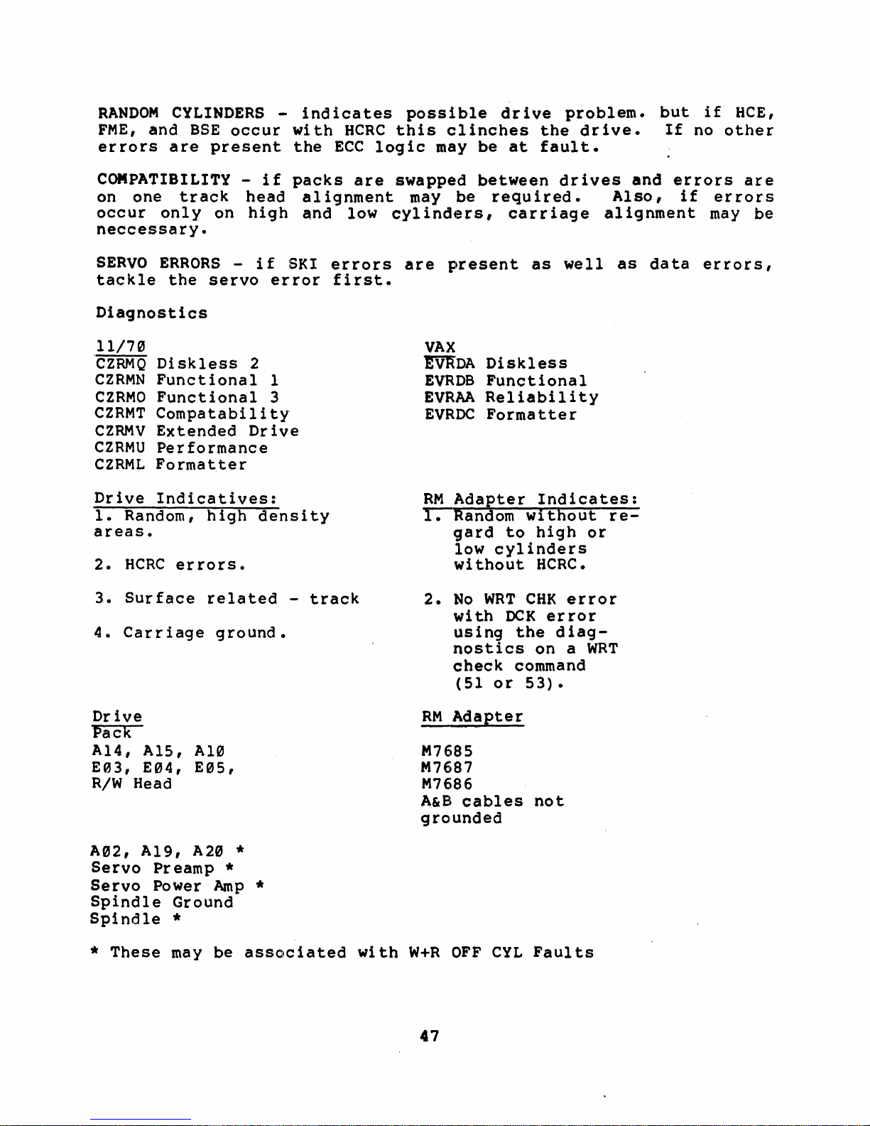
RANDOM
FME,
errors
and
CYLINDERS
BSE
occur
are
present
-
indicates
with
the
HCRC
ECC
possible
this
logic
clinches
may
be
drive
at
problem.
the
drive.
fault.
but
If
if
no
HeE,
other
COMPATIBILITY -if
on
one
occur
neccessary.
SERVO
tackle
Diagnostics
11/70
'CZRMQ
CZRMN
CZRMO
CZRMT
CZRMV
CZRMU
CZRML
Drive
1.
Random,
areas.
2.
HCRC
track
only
ERRORS -if
the servo
Di
skless
Functional
Functional
Compatability
Extended
Performance
Formatter
Indicatives:
errors.
on
high
head
high
2
Drive
density
packs
alignment
and
SKI
error
1
3
are
low
errors
first.
swapped
may
cylinders,
are
be
present
VAX
~DA
EVRDB
EVRAA
EVRDC
RM
Adapter
1. Random
gard
low
without
between
required.
carriage
as well
Diskless
Functional
Reliability
Formatter
Indicates:
without
to
high
cylinders
HCRC.
drives
or
and
errors
Also,
alignment
as
data
re-
if
errors,
are
errors
may
be
3.
Surface
4.
Carriage
Drive
Pack
Al4,
E03,
R/W
A02, A19,
Servo
Servo
Spindle
Spindle
*
Al5,
E04,
Head
These
Preamp
Power
Ground
*
may
related
ground.
Al0
E05,
A20
*
Amp
be
-
*
*
associated
track
with
2.
No
wi
using
nostics
check
(51
RM
Adapter
M7685
M7687
M7686
A&B
cables
grounded
W+R
OFF
WRT
th
or
CYL
CHK
OCK
er
the
diag-
on a WRT
command
53).
not
Faults
error
ror
47
Page 58

6.4
ERROR
REGISTER
2
6.4.1
Error
BIT
DPE
or
03
of
occur
Diagnostics
11/70
CZRMQ
CZRMN
CZRMO
CZRMU
Diskless
Functional
Functional
Performance
Drive
Not
Drive
Register
93
indicat"es
Write
(PAR)
the
anywhere
Caused
shi
2
3
DATA
Data
of
RMERI.
ft
2
2
PARITY
even
and
parity
Header
reg i ster
from
the
ERROR
(DPE)
was
Command.
Since
in
parity
the
shift
VAX
EVRDA
EVRDB
EVRAA
RM
Adapter
M7685
M7686
M5922, M5923
Terminator
Cables
detected
This
is
checked
RM
Adapter,
register
Diskless
Functional
Reliability
during
bit
back
a W:rite
also
at
the
The
to
the
sets
I)PE
Data
Bit
output
could
RH.
6.4.2
1.
2.
3.
4.
5.
Error
BIT 07
DVC
indicates
Write
a.
b.
c.
d.
e.
Head
Write
Input
+22
No
Head
head.
Write
ON
Cylinder
or
wr i ting.
Voltage
voltage
Register
DEVICE
Fault
winding
Driver
current
volts
write
Select
and
Read
Fault
is
low.
2
CHECK
one
of
shorted
output
to
to
Write
transitions
Fault"-
Fault
Fault
-
46v,
(DVC)
six
drive
-
low.
Write
Driver
with
multiple
-
simultaneous
On
Cylinder
5v,or
fault
replace
Driver
low.
Write
head
20v
conditions.
head.
low.
Gate
select.
Write
goes
away
positive"
asserted.
Usually
and
Read
while
or
a
bad
Gate.
reading
negative
6.
Servo
seg
uence
Fault
beg
ins.
No
No
dibits
LED
48
350ms
Indicator.
after
the
head
load
Page 59

Diagnostics
11/70
'CZRMP
CZRMQ
CZRMM
CZRMN
CZRMO
CZRMU
Diskless
Diskless
Functional
Functional
Extended
Performance
Drive
:Wr i te
Al7,
E02,
Head
Al7,
A0l,
Write
Faul
A10, A13, A02, A19,
E0l
Select
E01,
A02
and
A17, A02,
A0l,
On
A14, AlS
Cyl
W+R
Pack
A17,
A02, A19,
A08, A20,
Servo
Servo
Preamp
Power
Spindle
1
2
Drive
t
Fault
E0S, E04
Read
A19,
Faul
Fault
E0l,
t
E02,
amp
2
3
A08
A13
A07
A0l
VAX
'!VtrDA
EVRDB
EVRAA
RM
Adapter
M7684
M7686
-lSvolt
glitches
Diskless
Functional
Reliability
supply
6.4.3
Error
BIT 19
LBC
longer
and
Diagnostics
11/70
CZRMP
CZRMQ
CZRMN
CZRMO
CZRMU
Diskless
Diskless
Functional
Functional
Performance
Drive
A01,
AlS,
Cable
Servo
A10
Register
LOSS
indicates
than
Clock.
1
2
2
3
2
OF
BIT
that
400ns.
CLOCK
Bit
Bit
Clock
VAX
~DA
EVRDB
EVRAA
RM
R"1l)S7
M7686
49
(LBC)
Clock
is
Diskless
Functional
Reliability
Adapter
transitions
derived
were
from Read
absent
Clock
Page 60

6.4.4
Error
Register
2
BIT 11
LSC
1.
2.
3.
Diagnostics
11/7"
Same
as
Loss
Drive
See
LBC
if
6.4.5
Error
indicates
With
absent
With
address
Wi
th
the
LSC
will
of
LBC
Register
LOSS
the
longer
the
changes.
"Go" Bi t
both
Bit
is
set.
OF
one
~Go"
than
"Go"
be
Clock
2
SYSTEM
of
two
Bit
reset,
3usecs.
Bit
set,
set
set.
CLOCK
problems.
System
there
and
Bi t
VAX
Same
RM
as
Adapter
M7684
M7686
M7687
(LSC)
clock
Loss
if
LBC
is
clock
an
di
of
Bit
set
transition
absence
sappears,
Clock
of
LBC
are
Prom
and
BIT 12
lVC
asserted
Acknowledge"
Diagnostics
11/7"
CZRMP
CZRMQ
CZRMM
CZRMN
Diskless
Diskless
Functional
Functional
Drive
A17,
A"l
Cable
6.4.6
Error
BIT 13
OPE
INVALID
indicates
when
1
2
1
2
Register
OPERATOR
indicates
COMMAND
that
any
command
is
attempted.
2
PLUG
the
drive
(IVC)
"Volume
VAX
EVRDA
EVRDB
RM
M7684
M7686
ERROR
address
Valid"
except
Diskless
Functional
Adapter
(OPE)
"Read
plug
or
"Unit
In
is
removed.
Ready"
Preset"
or"
is
not
Pack
5"
Page 61

Diagnostics
11/70
All
Drive
Address
Al?,
Cable
1.
2.
plug
removed.
Error
BIT 14
SKI
indicates
The
drive
The
Forward
while
a
re
be
reasons:
a.
A
EOT
b.
into
cylinders
Register
SEEK
is
heads
ing
are
per
mis-position
on
the
Veloc i ty
the
2
INCOMPLETE
one
of
three
unable
or
Reverse
to
supposed
fo
rmed •
occurred
next
seek.
problem
EOT.
0
and
This
822.
VAX
XIT
RM
Adapter
M7684
M7686
(SKI)
problems
do a seek
EOT's
to
EO'I" s could
caused
would
(guard
be
On
and
Related
an
occur
in
the servo
within
bands)
Cylinder
be
detected
the
drive
to
b.
overshoot
when
S00ms.
were
or
was
below.
of
seeking
logic:
detected
while
for
forced
the
close
seeks
three
to
servo
to
3.
Diagnostics
11/70
CZRMQ
CZRMN
CZRMU
CZRMU
Diskless
Functional
Extended
Performance
c.
A
Faulty
cylinder
drive.
an
interface
er.
This
Address
bogus
interface
due
RTZ,
be
to
improperly
due
2
end
address
This
is
Error
cylinder
problem
head
to
faulty
2
of
travel
greater
SKI
problem
because
and
error
between
the
abort
address
other
mis-selection,
funtioning.
error
(EOT)
than
should
RM
Adapter
the
into
symptoms
commands
logic.
VAX
!'V'R"DA
EVRDB
EVRAA
detect
822
not
occur
the
drive
would
command
the
drive.
would
This
form
Diskless
Functional
Reliability
logic.
was
and
such
of
loaded
unless
the
flag
before
If
there
be
noticed.
as
SKI
RM
an
loading
Read,
could
into
there
Adapt-
Invalid
were
Write,
the
is
a
an
HCE
also
Sl
Page 62

Drive
A0S,
A07, A06, A19,
A12, A18, A20,
Servo
Power
Amp
Transducer
Servo
Servo
Binding
Preamp
Head
Carriage
A02
Way
Bearings
RM
Adapter
M7684
M7686
6.4.8
Error
BIT
BSE
word
zero
to
because
the
error
Diagnostics
11/70
CZRMP
CZRMQ
CZRMN
CZRMO
CZRML
CZRMU
Diskless
Diskless
Functional
Functional
Formatter
Performance
Drive
Not
Drive
No
If
Read
Read
Errors.
Errors
Register
15
indicates
were
to
the
Bad
but
Caused
Are
BAD
SECTOR
read
indicate
operating
the
format
Sector
HCRC
1
2
2
3
Exerciser
If
See
DCK
Present
2
that
as
File.
will
ERROR
bit
a
0.
a bad
system
programs
The
also
.
(BSE)
14
and
Bl t 14
sector.
error
error
be
will
set.
or
and
This
log
flag
will
VAX
~DA
EVRDB
EVRDC
EVRAA
RM
Diskless
Functional
Formatter
Reliability
Adapter
M7685
M7686
M5922, M5923
15
of
15
error
or
these
show up
are
dur
the
ing
first
wr i tten
is
transparent
diagnostics
bad
sectors
during
header
as
in
a
read
a
52
Page 63

7.0
BOOTSTRAP
PROBLEMS
Bootstrap
by
customers
throughout
that
tells
words)
programs
Moni
tor.
problems
the
the
into
memory.
off
The syst:em
commands from
assumes
Unibus)
there
hardware
1.
the
to
be
are
a few
problem's:
Halt
basic
system
bits.
the
condition
or
the
error
2.
Determine
have
the
a good
the
like
are
and
may
system.
disk
the
disk
the
system
functioning
basic
the
CPU
Init)
If
there
section
exists,
standard
indications.
if
a
bootable
"only"
choice
"Expand"
the
customer's
one
indicate
Briefly,
to
read
This
is
into
block
memory
then
customer's
components
completely.
steps
(do
not
and
examine
are
in
this
examine
PDPll
there
image and
customer
(keep
Operating
of
the
very
any
the
(Cyl
S,
contains
'that
considered
operator.
to
follow
hit
the
the
any
error
manual
the
Memory
are~any
backup.
it
write
System
software.
common
of
a
variety
bootstrap
Sector
S,
a
program
forms
·up"
head
the
and
This
(CPU, Memory,
When
this
that
start
disk
bit
for
11/7S
switch
registers
indications
that
maintenance
par i ty
other
try
A
disk
them.
diagnostic
protected).
does
not
sympto~s
of
is
a
small
S) 1
that
Operating
ready
entire
System
operation
should
isolate
which
for
bit.
reg
packs
Be
If
isters
on
sure
pack
Also
use
interruptors
expressed
problems
program
block
reads
System
to
accept
operation
Disk
fails,
issues
any
error
proceed
no
error
registers
for
site
not
is
to
usually
remember
(256
more
and
any
a
to
any
that
use
3.
4.
If
you
have a multi-drive
another
drive.
compatib:ility
appropriate
If
no
other
device
to
run
such
some
instruction
subsystem
sti
11
the
of
If
Unibus.
problem.
no
assume
refer
diagnostics.
the
apparent
the
to
the
or
section).
packs
as
a
diagnostics.
exerciser,
possibi
DECX-Il
hardware
data
section
This
data
are
tape
1 i
on
available,
unit,
te~t
If
ty
of
should
the
on
Data
system,
may
determine
base
Floppy
Be
ROM
no
problems
device
be
problem
pack
to
Base
try
to
corruption
try
to
disk,
sure
Bootstrap,
interaction
run
can
be
to
be
corrupted.
Corruption.
boot
if
problem
bootstrap
etc.
to
use
are
found
isolate
found,
the
pack
you
have
another
In
order
the
basic
there
problems
this
you
Please
on
a
(see
CPU
disk
is
on
type
must
53
Page 64

8.g
COMPATIBILITY
Compatibility
disk
Spec
drives
for
the
mechanical
carriage
It
is
between
way
possible
drives
misadjustment
8.1
COMPATIBILITY
Compatibility
read
data
drives.
incorrectly
common) •
usually
only
at
any
which
has
Please
separate
drive.
when
time
drive
been
note
recorded
the
used
error
Here
is
the
and
'read
drive.
tolerances
procedures.
to
but
or a defective
problems
on a
Two
pack
distinct
(uncommon)
There
are
on
pack
the
the
system
pack
in
that
each
symptoms
are
some
ability
the
data
Compatibility
that
have
what
really
PROBLEMS
are
defined
that
areas
or
a·
also
two
different
is
formatted
is
was
formatted
order
of
to
the
that
hints
to
interchange
on
the
is
are
defined
seems
is
an
component.
was
written
arise,
drive
data
drives.
and
in
use.
and
isolate
two
data
are
helpful
on
isolating
packs
made
possible
by
to
be a
ELECTRICAL
as
an
inability
on a
the
is
reading
areas
the
It
The
is
on
in
header
data
useful
how
which
areas
in
a
drive
media
within
the
by
the
head
compatibility
PROBLEM
of
different
data
incorrectly
each
sector
area
area
can
to
many
drive
(Header
drives
has
and
isolating
problem:
bet'lI7een
error
keeping
a1
ignment
problem
due
a
drive
drive
was
written
that
is
recorded
be
written
determine
the
a
problem.
Data)
the
failing
like
rate
the
and
to
to
or
(more
are
on
pack
have
•
•
•
Insure
each
CZRMU)
scratch
Please
all
If
If
note
drives.
on a
on a
drive.
and
having
have
run"
problems
problems
suspected
drive
or
Reliability
pack
that
that
11/70,
VAX,
run
run
Then move
Read
All".
reading
in
the
runs
is
bad
spots
the
Formatter
the
Any
reading
original
the
Performance
(VAX
-
formatted
mayor
Compatability
EVRAC
pack
to
errors
the
the
the
would
original
pack,
drive
EVRAA)
on
may
nGt be
diagnostic
and
next
indicate
data.
a
problem
where
Exerciser
diagnostic
that
same
picked
format
(or
suspect)
If
the
(11/70
drive.
(CZRMT).
the
a
drive
all
drives
should
pack
on a
up on
fi
rst
drive
is
be
was
-
formatted.
•
If
the
data
before
compatibility
packs
be
alignments,
sure
problem
to
have
or
replacing
the
appears
customer
hardware.
only
back
on
up
customer
his
data
54
Page 65

8.2
The
INCOMPATIBILITY
following
items
SYMPTOMS
are
causes
of
incompatibility
symp~oms:
8.3
The
1.
2.
3.
4.
S.
following
Head
Carriage
Dirty
Write
Bad
ERROR
compatibility
failing
unit
•
OCK
incompatibility.
or
probably
then
Be
pack
HCRC
compatible.
matrix
this
the
alignments
HCRC
miscalculation
drives
Alignment
Head~
Current
Pack
SYMPTOMS
is
problems
and/or
errors
heads.
a bad
sure
as
to
a
errors
module
type
pack
errors
and would
Way
Alignment
-
a
list
exist.
adjustment
are
If
this
needed
head
try
to
pack
could
indicate
In
E04
of
problem,
was
have
between
E01,
E02,
of
Alsc.
needed
the
It
most
is
symptom
on
one
or
head
simulate
also
that
this
may
case,
be
be
originally
been
of
be
the
due
performed
A12
error
included
common
usually
of
the
matrix
the
exhibit
at
sure
drive
Header
to
a
symptoms
to
correct
error
common
exists
drives.
card
failure
this
the
head
fault
pack
alignment,
again.
to
determine
formatted
since
may
CRC
failure
are
to
head
alignment
If
E04
with
type
format
and
that
indicate
word
of
the
encountered
the
most
the
problem:
symptom
a
specific
probable
of
alignment
may
be
at
more
of
than
symptom.
may
a ,bad
When
time.
in
on
if
faced
which
any
Constant
a
possible
one
M768S.
dr
head
is
most
is
fault.
not
head
with
drive
head
of
when
ive
OK
one
be
or
the
•
If
the
data
failing
(AI3),
Matrix
problem
that
write
Module
is
incompatible
circuits
E04.
was
would
current
isolated
be
source
5S
with
to
other
the
(E01,
a
dr
Write
ive
that
drives
is
the
Precompensation
E02,
A13),
wr i ting
probable
or
the
Page 66

9.0
DATA
BASE
CORRUPTION
This
section
customer's
"crashed",
rebuilding
This
problem
109gin9
of
the
of
isolating
(isolation
type
to
even
one
of
such
software.
could
•
•
data.
"deteriorated"
the
file
on
customer's
this
technique)
failures
areas
use:
Determine
talking
engineers,
of
any
or
SKI
place
to
note
Unibus
reports,
Check
error
the
one
not
to
RH
big
detect
or
destroying
addresses
The
packs
becomes
the
disk
sensitivity
type
can
as
the
The
following
the
with
etc.
intermittent
that
on
the
any
or
Memory
site
for
a
Register
Control
fault
an
from
data.
common
from
very
of
that
be
attributed
CPU,
immediate
the
would
pack.
system
logs,
history
1
Status
-
If
error.
the·
problems
and
a
back-up
hard
is
usually
to
failure
is
Unibus,
operators,
Check
positioning
indicate
When
type
type
etc.
of
or
for
you
disk
symptoms
can't
to
this
explained
to
memory,
is
a
general
history
previous
checking
errors
problem).
to
MASSBUS
a
I
Register.
drop
So
it
without
that
arei
be
tape
isolate
highly
type
hinges
to
the
disk
of
users,
error
problems
a
dr
ive
(this
get
additional
Par i ty
MASSBUS
an
even
is
possible
knowledge
involve
the
brought
or
back-up
because
intermittent.
of
failure,
on
a
good
the
customer.
subsystem
memory
isolation
whole
customer,
logs
going
the
error
would
Check
Errors
Data
parity
Parity
number
to
a
~loss
system
up
"hung",
without
disk
the
8ecause
the
success
acti.on
and
management,
process
system
for
such
to
log,
through
,evidence
as
HCE's,
the
be
indicate
field
service
information.
ei
ther
E~rror
detection
of
bits
you
transfer
of
loosing
of
packs.
error
plan
This
also
that
other
wrong
sure
a
CPU
in
in
has
do
data
or
a
or
•
•
If
you
system,
resides
file
may
problem
Note
of
any
new
office
power,
fluctuation,
balancing
of
problems.
site
static
if
conditions
suspect
change
the
unit
on a different
be
available
on
the
original
changes
in
equipment
or
industr
loading,
grounding,
ground
have
a
Have
necessary.
(add
ial
high
an
that
system
disk
numbers
drive.
to
analyze
system
the
environment
ons,
equipment)
failures,
probabil i ty
environmental
Be
aware
may
be
drive
so
In
disk
air
etc.
of
excessive.
on
that
this
if
case
you
the
suspect:
drive.
such
as
conditioners,
that
on
the
would
system.
improper
of
causing
specialist
any
heat,
a
multi-drive
system
the
error
installation
or
affect
phase/load
these
check
humidity
Disk
a
disk
other
Power
type
log
the
the
or
56
Page 67

•
When
to
Mgmt,
you do
start
an~mory
diagnostics
3
that
you
get
all
the
(unless
definitely
system
CPU,
time
Floating
diagnostics
you
have
have a disk
to
run
diagnostics,
Point
before
discovered
problem).
(if
applicable,)
you
start
in
steps
be
with
1,2,
sure
Mem
disk
and
While
the
CPU,
be
discretion
•
If
the
tapes
exerciser
thru
•
If
and
isolate
on
jumpers
registers
to
•
If
have
indiscriminately
write
corrupted
the
any
there
caused
Performance
address
Formatter
running
system
Hem.,
helpful
you
default
all
you
not
the
try
the
you
no
circuits.
pack.
bad
was a
-
RH
as
have
and
di
allow
available
have
to
a
the
RH
system.
for
for
RH70
isolate
error
pack
Remember you
spots
the
data
Exerciser
284,
(EVRAC)
diagnostics
especially
and
RM
in
isolating
to
the
a
DECX11
word
count
sks
for
isolated
particular
controller
This
the
the
CSR,
specific
in
the
bit
symptoms
on
and
doing
on
the
write
corruption.
"R"
Command
"Read
Adapter.
severity).
system
values
on
the
at
least
memory.
the
drive
usually
Vector
another
problem
the
This
pack
can
a
must
pack;
error
diagnostic
All"
check
the
all
+Svol t regulators
Vibration
these
exerciser,
in
system.
one
failure
there
by
using
only
Address,
device.
backplane
to
the
to
go
and
be
spiral
have
any
new
that
For
with
SWR
command.
the
problems.
each
I/O
When
full
to
pass
the
may be a
another
involves
In
the
slot.
RM05
on,
the
the
problem
verified
read
header
previous
bad
was
unrecoverable
the
(CZRMU),
:I:
3.
WRITE
power
testing
be
sure
module
of
disk
RH
chang
and
11/70,
drive
drive
by
knowledge
sectors
11/70,
Load
For
supplies
for
may
(Please
to
for
running
relocation
subsystem
quick
that
ing
number
be
itself
is
writing
is
taking
and
data
ind
use
and
VAX,
PROTECT
way
may
in
icate
start
on
the
also
use
vary
the
the
to
be
some
of
sure
and
the
the
of
of
that
the
use
THE
DRIVE!!!
Above
what
and
troubleshoot
all,
you
the
keep
are
doing,
complexity
this
NOTE
the
type
customer
why
you
of
57
informed
are
of
trying
problem.
doing
on
it
to
Page 68

18.8
DRIVE
NOT
READY
OR
DRIVE
HANGS
This
the
by
section
drive
the
actual
"Offline".
There
are
problems.
•
•
•
deals
drops
software).
hardware
three
Loss
Loss
of
Volume
IVC.
Dr
ive
command
This
under
by
numerous
isolate
the
registers.
of
bits:
failure
the
with
offline
This
error,
basic
the
does
and
symptom
the
customer
this
RMOS)
VV,
MOL,
problems
or
section
such
symptoms
VV
Bit
Valid
not
return
does
typically
problems
type
occurs,
Pay
particular
not
PIP,
appears
as
due
(VV
bit)
not
I s
have
operating
throughout
of
failure,
halt
set
GO, OPR,
where
to
should
DVC
to
to
loss
without
to
evidences
the
notice
and
hang
has
look
a
any
sytem
the
ORO
the
up
not
caused
for
of
MOL.
ready
spec
system
the
one
status
or
only
(cannont
be
the
if
itself
system.
must
and
to
PSEL.
symptoms
referenced
the
in
See
loss
condi
ic
dr
these
IVC.
of
tion
er
ror
intermittently
and
be
can
on
examine
drive
of
ready
the
are
be
accessed
when
ive
types
MOL.
after
symptom.
bE~
In
order
sl
te
the
following
that
an
to
go
of
See
caused
to
when
RM05
(bit
a
7
The
condition
failure,
depend
bits.
latching
i.e.
on
Also
or
the
see
errors.
of
these
the
RM05
conditions
RM02/03
bits
logic.
exemplified
Technical
indicate
Specific
Tip
the
by
area
failures
these
on
Fault
of
will
status
Card
the
58
Page 69

11.0
DUAL
PORT
PROBLEMS
This
-dual
logic
section
port
is
deciding
all
dual
module,
MASSBUS
should
• The
•
EXAMPLE:
access:
located
which
port
one
cable
know
about
Adapter
backplane
Port
Dual
backplane
There
physically
may
addresses
in
MASSBUS
re1.ated
of
the
(Be06S
the
dual
port
backplane.
B
are
Port
may
be
stalected
typical
-CR
the
accesses
M5922
or
dual
option
two
M5923
also
jumper
not
cabled
problems
port
RM
hang/se1ect-.
Adapter
the
problems
or
M5923
BC06R).
port
option:
is
In
modules,
required~
5 - 6
be
on
two
out,
drives
on
the
alternate
with
and
provides
drive
can
be
MASSBUS
There
implemented
addition
and
of
Jl
with
same
massbus
ports.
symptoms
All
at
anyone
isolated
are
by
to
the
the
described
Port"
the
arbitration
function
time.
to
transceivers,
several
a
jumper
the
MASSBUS
things
jumper
cables
Single
jumper
same
even
5 - 6
unit
though
the
on
Nearly
M7686
or
one
the
on
the
for
Port
in
Jl
number
they
as
of
a
RM
MASSBUS
(drive
MASSBUS
•
A
locked
B
The
are
MOL
spun
switch
on A port)
port
select
loaded,
goes
from
down,
change
ILLEGAL CONFIGURATION
A
Port
RM05
but
and
swi
will
low
back
would
Drive
B
tch
to
occur
Port
cannot
not
high.
up
0
effect
This
again.
whenever
Locked
on
B
be
changed
the
occurs
The
port
the
selection
when
normal
pack
A
RM05
Drive
B
Port
once
port
is
Port
0
the
the
pack
changed.
locked
on
heads
until
select
A
is
S9
Page 70

•
"Init"
drive
doesn't
B
port)..
unibus
Attention
register
pulse
is
clear
"Init"
selected
bits
(RMAS)
corresponding
locked
on
the
does
ATA
Be
careful
to
on
Attention
other
not
on-the
bit
clear
opposite
must
port.
clear
other
when
the
when
Attention
ports,
be
written
bit
the
drive
port.
drive
running
bits.
even
_
is
DECXll
the
attention
with
though
Attn
(i
.e.
select
In
order
a
bit
Unibus
as
·one"
the
if
locked
it
to
clear
summary
to
drive
the
Init
on
uses
the
is
EXAMPLE:
the
000002
•
Customer
known
register.
register
depending
oppos i te
instructions
• For
ideal
Exerciser
B
port
to
to
11/70
for
If
dual
Attention
the
written
have
One
may
on
po r
t.
when
systems,
worse
from
ported
RMAS
register
handler-for
problems
reason
be
read
the
Be
addressing
case
each
drive
bit
can
is
that
as
condition
sure
the
Performance
diagnostic
CPU
simultaneously.
only
on
dual
when
all
of
tha
the
1
is
be
the
ported
dea 1 ing
the
upper
"ones"
the
t
customer
RMAS
testing.
locked
cleared
B
MASSBUS.
Attn
register.
Exerciser
on
drives
wi
th
byte
or
bits
s
Run
the
A
port,
by
writing
have
the
of
all
been
RPAS
the
RPAS
"zeros"
on
use
"byte"
(CZRMU)
Performance
a
the
is
60
Page 71

12.
In
dr
to
"
the
ives,
the
PACK
RM0S,
the
special
manufacturing
information
following)
read
on
the
complexity
and
furthermore,
RM0S's
other
RM0S.
with
vendors
We
pack
and
of
RM0S-·P
test
ERRORS
as
has
on
is
use.d
fc,)r
other
these
the
that
each
in
all
become
information
the
wservo
both
timing
Wdata
surfaces
packs
RM0S
packs.
mayor
pack
before
other
part
for
to
the
error
We
may
third
of
the
that
is
surface
posi
tioning
synchronize
w
of
RM05-P
rate
have
not
we
is
specifications
no
function
sell
generation
electronics
prerecorded
w
of
(in
data
the
the
pack.
only
control
satisfactorily
it.
or
•.
the
seekings
being
Because
pack
apply
over
higher
This
at
pack.
written
we
the
disk
is
due
time
of
This
&
Track
and
of
the
recommend
to
only
packs
in
of
the
•
No
errors
this
•
•
No
is
Not
errors
the
more
uncorrectable·
defective
per
surface.
•
If
it
you
should
diagnosfrc
scratch
• Random
also
OCK's & ECHis.
•
Intermittent
wi
th
wobble)
using
Manual
Installation
allowed
is
the
allowed
Bad
Sector
than
sectors
have
not
meaia
pack
DeH
errors
run
into
excessive
or
worn
the
procedure
under
boot
20
errors
See
a
pack
be
on
a
HCE
wTrack
&
Check
on
cylinder
area.
on
cylinder
File
uncorrectable
per
per
12.4.
that
used
(XXDP).
which
to
could
pack
This
usually
& SKI
radial
spindle
in
Following
Out
area.
"PX"
pack
exceeds
for
customer
It
run
be
generated
that
errors
runout
bearings.
the
Section.
0,
track
822,
track
sectors
packs;
and
not
any
could
however
diagnostics.
has
looks
may
of
one
like
be
the
This
Drive
Check"
0
and
18,
per"
P"
not
more
of
more
than
these
applications
be
by
a
pack.
surface
a
head
attributed
servo
can
tracks
be
Hardware
-
Page
1,
because
because
this
packs;
than
10
errors
conditions,
or
as
used
as
You
that
gives
problem.
to
a
pack
(pack
checked
Maintenance
2-80
of
no
48
a
a
may
by
the
•
HCRC
pack.
and
If
addresses,
errors
due
unrecoverable
map
of
the
also
flag
DTE
errors
these
this
to
(hard)
operating
them.
can
errors
indicates
the
errors
system.
pack
61
be
occur
the
and
caused
consistently
pack
should
flagged
The
Formatter
by
is
be
bad
at
fault.
classified
in
the
spots
on
specific
bad
program
on
These
block
will
the
as
Page 72

13.9
UNEXPECTED
ATTENTION
BITS
Attention
controller)
(including
program
interrupts
diagnostics)
po·rted
for
15
the
the
the
of
RMAS
drive
drives
B
the
register;
Attention
Drive
Please
9.
note
•
If
switches
all
This
Unit
system.
•
Be
the
bits
that
the
•
Port.
RMDS
unit
bit
It
is
the
you
signals,
aware
RMAS
are
some
RM
Adapter)
to
Each·
have
drive
2
The
register.
the
number
setting
rarely
following
intend
on
the
would be
if
the
customer
that
register
indicator
important
on
software
has
attention
condi
tion
Each
bit
position
i.e.,
is
usually
a
problem
hints:
to
work on a
M5922
including
advisable
MASSBUS
on
(flag)
event
the
a
separate
bits;
of
drive's
bit
9
caused
by
or
M5923
Attention
when
is
running
parity
the
MASSBUS.
bits
has
MASSBUS.
(either
one
the
Attn
bit
in
the
of
the
by
itself.
dr
ive
modules,
bits,
using
on
is
not
to
occurred
This
operating
attention
for
the
bi t is
is
also
register
RMAS
something
off-l
this
from
the
other
used
the
in
bit
is
systems
bit
A
Port
sampled
accessible
corresponds
register
happening
ine
throw
will
the
RM05
Fi~a1d
drives
when
accessing
RH
an
used
(CPU
RM05
for
or
and·
and
as
dual
one
bi
t
in
to
is
the
in
both
disable
MASSBUS.
'rest
on
the
The
take
both
•
Any
MCPE,
•
Many
Attention"
are
of
•
Attn
which
following
notice
A
and/or
"hung"
MOPE
Diagnostic
rarely
the
conditions
in
the
causes
is
a
of
the
B
bits
Attn
or
or
Attn
RH
Bits
PAR)
"Attention
bit
sets
the
Table
of
condition
are
set
(with
is
usually
error
problems
described
SC
trap
(program
conditions
of
or
cleared.
no
printouts
from
and
in
(bit
14
that
port
selection
other
traced
begin
an
Off-line
only
Table
of
RMCSl)
interrupt).
set
indications
to
the
M7686.
with
indicate
13-1
has
which
the
Attention
in
order
such
"Unexpected
Unit,."
These
that
occured.
sets
bit;
to
see
as
one
Intr
if
62
Page 73
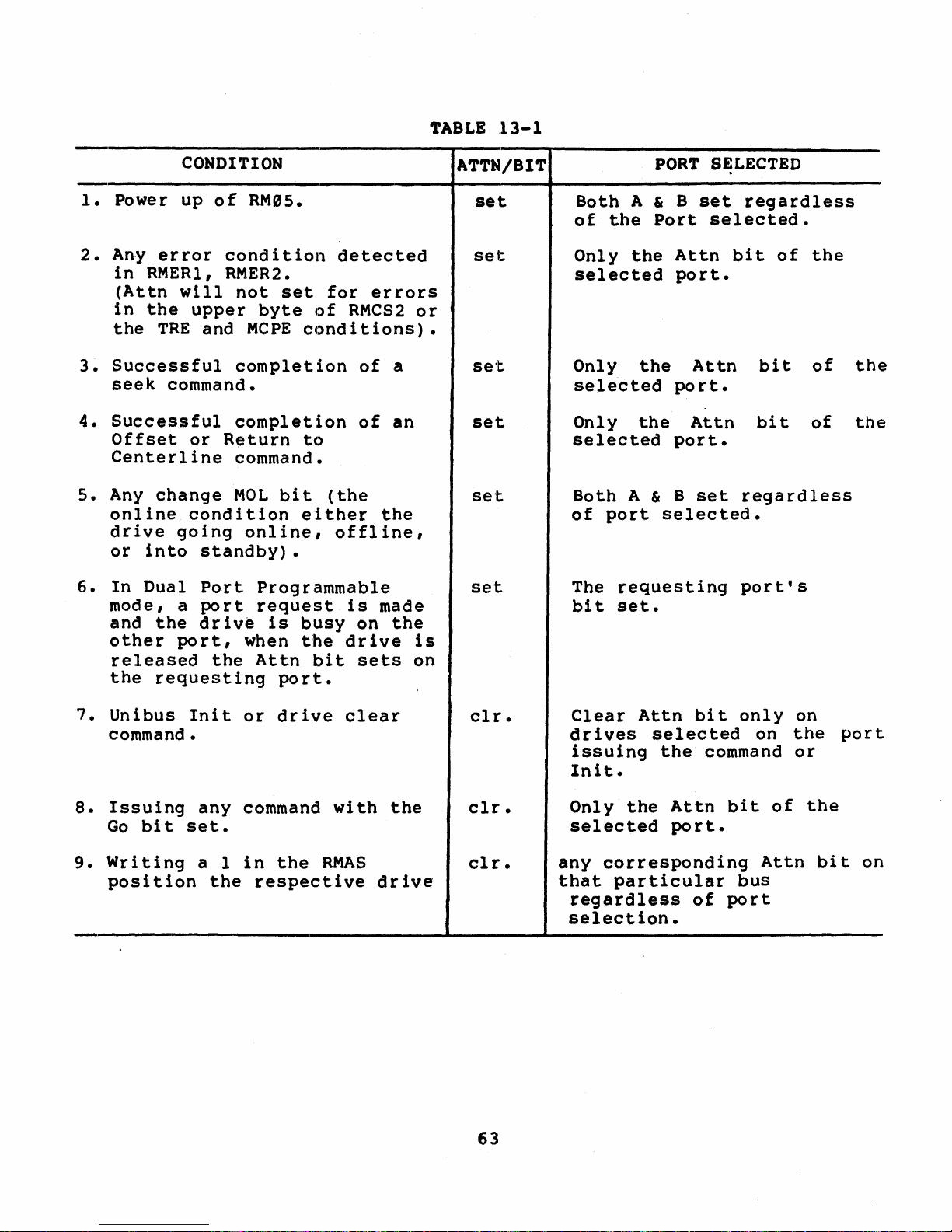
TABLE
13-1
1.
Power
2.
Any
in
(Attn
in
the
3.
Successful
seek
4.
Successful
Offset
Centerline
s. Any
online
drive
or
6.
In
mode,
and
other
released
the
CONDITION
up
of
error
RMER1,
will
the
upper
TRE
and
command.
or
change
condition
going
into
Dual
a
the
standby).
Port
port
drive
port,
the
requesting
RM~5.
condition
RMER2.
not
set
byte
MCPE
conditions).
completion
completion
Return
to
command.
MOL
bit
either
online,
Programmable
request
is
busy
when
the
Attn
port.
detected
for
of
RMCS2
(the
offline,
is
drive
bit
errors
of
of
the
made
on
sets
a
an
the
or
is
on
ATTN/BIT
set
set
set
set
set
set
Both
of
Only
A & B
the
the
selected
Only
selected
Only
selected
Both
of
The
bit
A & B
port
requesting
set.
PORT
Port
Attn
port.
the
port.
the
port.
selected.
SE;LECTED
set
regardless
selected.
bit
Attn
Attn
set
bit
regardless
port's
bit
of
the
of
of
the
the
7.
Unibus
command.
8.
Issuing
Go
9.
Writing
position
bit
Init
any
set.
a 1
the
or
drive
command
in
the
respective
clear
with
RMAS
the
drive
clr.
clr.
clr.
63
Clear
dr
ives
issuing
Init.
Only
the
selected
any
corresponding
that
particular
regardless
selection.
Attn
selected
the
Attn
port.
bit
only
command
bit
bus
of
port
on
of
Attn
on
the
or
the
bit
port
on
Page 74

14.0
If
the
ADJUSTMENTS
drive
Position
be
grossly
one
no
The
has
reason
drastically,
than
to
afterwards.
Gain
off,
tampered
for
and
do
an
adjustments;
Integrator
replace
with
module
replacement
it
would
adjustment
negative
Gain,
the
the
be
or
positive
and
Fine
associated
Velocity
module
adjustment-previous
is
better
and
that
have
a
to
replace
another
component
5
volt,
Gain
are
providing
to
your
has
the
module now,
failure
Course
found
to
you know
checking.
degraded
shortly
14.1
Extended
VAX
SERVO
Drive
diagnostic
troubleshooting
necessary
Two
known symptoms
1.
to
Forward
second.
2.
The
Seek
Both
can
Transducer
14.2
In
If
adjusted
these
cause
FINE
some
cases
oscillation
too
symptoms
the
can
ADJUSTMENTS
RM0S
11/70
(EVRDB)
velocity
do
the
timing
that
and
Reverse
Maximum
time
is
Seek
at
indicate
problem,
also.
VELOCITY
when
of
far
off.
GAIN
the
the
diagnostic
timing
problems.
tests
the
timing
Seek
the
but
head
Time
load
is
minimum.
a
problem.
the
occurs
positions
Readjustment
tests
Remember
on
the
test
times
too
Servo
exists,
will
(CZRMV)
are
that
11/7e.
indicates
differ
slow
although
Usually
Power
Amp
osciallation
Fine
correct
and
a
great
a KWllP
are:
more
A20,
or
Velocity
the
Functional
tool
Clock
than
1
the
Al9,
the
will
Veloc i ty
start.
Gain
oscillations.
RM05
for
is
milli-
Average
or
A07
is
•
•
• Adj
If
oscillation
because
the
field
heads
the
will
Scope
Observe
ust
now
within
Tack
in
the
have
test
the
the
persists
Rod
coil
maximum
point
see
pot
C
of
Hz
sinewave.
until
specifications
change
Magnet
to
is
collapse
velocity,
of
the
the
of
64
the
A20
sinewave
range
Tach
low
magnetism.
and
and
the
hit
card.
dissappears.
for
timing
Rod
Magnet.
result
the
crash
adjustments.
This
This
will
will
be
stop.
You
is
that
are
done
cause
the
Page 75

14.3
If
head
have
the
misaligned
HEAD
al
ALIGNMENT
ignment.
customer
drive
is
back
before
necessary
up
all
doing
and
his
the
the
offset
packs
that
alignment.
is
were
more
wi
than
i t
ten
200MV,
on
the
6S
Page 76

15.9
FLOW
DIAGRAMS/TEST
POINTS
The
flow
diagram
troubleshooting
• Power
•
.•
•
•
These
can
correlate
labeled
In
addition
give
you
used
the
following:
•
•
•
These
tables
RM9s
RM0s
NRZ
RM0s
diagrams
as
Figures
the
in
conjunction
Print
Proper
Signal
tables
are
drives.
contained
the
following
Distribution
First
Seek
Forward/Reverse
to
MFM
Write
Unload/Power
give
the
the
flows
15-1
to
the
proper
flow
test
with
Set
Cross
Test
Point
Names
are
for
labeled
both
the
in
areas
(one
(four
flows)
Seek
Data
(two
Off/Emergency
print
to
through
the
set
print
15-5.
diagram'
points
the
to
flow
Reference
as
Tables
NON-VDE
this
section
of
the
flow)
(four
flows)
cross
set.
there
scope.
diagrams.
Number
15-1
and
RM9s
flows)
Retract
reference
The
are
These
through
VDE
versions
are
Disk
(two flows.)
flow
several
tables
The
tables
to
~id
Drive~
numbers
diagrams
tables
are
will
15-8.
of
the
you
so
which
to
list
These
RM05
in
you
are
be
66
Page 77

2OIW220
ENABlE
GENERATE
ENABlES
VACPOWER
13
+2OV
RELAY
COilS
803
803
803
822
"IJ
....
\Q
s:::
803
,.,
DEVELOPS
(D
APPlYAC
-16V
FOR
TO
A101
+16VSENSE
....
TRIAC
VI
803
I
.-
TURN
ON
-T1
ENABLE
DEVELOPS
DEVELOPS
16VAC
TO
BLOWER
16.46VAC
BRAKING
~
MOTOR
BRIOGECR14
m
803
804
VI
0\
~
DEVELOPS
'8
DEVElOPS
-13VFOR
28.20.10
EMERGENCY
.:
VAC
RETRACTCKT
(D
803
803
803
822
,.,
812
+9.7
SENSE
0
....
+5V REGUlATOR
til
CAl
CHASSIS) 844
r1'
SERVO
PREAMP
762
,.,
....
842
C"
5V
REGULATOR
c:
tAl
CHASSIS)
rt'
SERVO
PREAMP
762
....
0
::s
lOGIC
CHASSIS
842
IAl
CHASSIS)
REAOIWRITE
IAJ
CHASSIS)
CHASSIS
612
READtWRITE
VOICE
COl..
IAl
CHASSIS)
DEVELOPS
fA 1
POWER
SUPPLY)
CHASSIS
612
:t46VOLTS
POWER
AMP 832
803
822
RMOS
POWER
DISTRIBUTION
Cl-Ot
••
Page 78

ts.1
....
\Q
c::
,.,
CD
~
U1
I
N
~
&
U1
..,
....
,.,
CD
rt'
PICK
OUT
til
CD
CD
~
28
-
til
::r
CB3TRI"PEO
CD
CD
rt'
PACK
~
MOTOR
STARTS
0
104
1104
1104 1104
H\
.e.
IOC
tf:trlf
I
ENABlE
I
I
READY
,
lHZOSC
n
FLASHER
K3 K4 K5
lEO
82
Cl·_
RMOS
FIRST
SEEK
Page 79

82
PICK
OUT
.-----.
TO
NeXT
DRIVE
82
-UNlOAD
HEADS
>---...."
a_
...,
....
\Q
C
..,
(D
~
\on
,
'"
~
St
U1
..
....
.,
en
C'1'
fI)
CD
CD
i'\
-
fI)
:::T
CD
CD
C'1'
'"
0
~
~
Page 80

SETl.OAD
LAtCH
TURN
ON
Q1.
START
FWD
MOTION
CARRIAGE
ACCELERATES
FWD
AT7
IPS
FWOEOT
DETECTED
192
RESET
SlOPE
FIF
0131072
RMOS
FIRST
SEEK
YES
FAUlT
TO
INTERFACE
t'I,1
....
\Q
c:
..,
en
....
U1
I
N
~
S
U1
t'I,1
....
..,
(I)
r1'
til
en
en
~
-
til
::T
en
en
rt
W
0
1"'1\
~
Page 81

t'Ij
I-h
EOTOETECT
YES
\Q
A-
t:
..,
184
(I)
~
U1
I
l\,)
~
S
U1
t'Ij
I-h
.....
..,
...
Ul
rt
WHBIRNE
ANALOG
til
ISOVOllS
(I)
193
(I)
~
-
73
73
73
til
::r
193
-
..
(I)
(I)
rt
.&110
0
t1\
.&110
~
Page 82

ENABtE
SELECTED
CHANNEL
REOTAANS
DIRECTION
FIF
1 A
LOGICAl
0 IS FWD A2-A12-138
r-----------
__
--~
A
LOGICAl
1 IS
REV'
CARRY
BIT
TO
LOW
ORDER
ADDER
122 -
123
ON
CYl • CYl
SEL • SER
ROY
-START
SEEK
GATE
....,
U1
I
w
~
o
.,
C
Of
.,
Oa
"-
"
(I)
<
(I)
.,
m
(I)
en
(I)
(I)
~
-
en
::T
(I)
(I)
rt
Page 83

DIRECTION
BIT
EW
ADDRESS
20
CONDITION
DIRECTION
F-F
72
CONTROLLER
.~_
...
____
...
DROPS
TAG
01
24
73
INmATE
30
S
ONE
SHOT
73
OROPONCYl
AND
SEEK
END
TO
INTERFACE
73
203
DIGITAl
TO
ANALOG
CONVERTER
DIFFERENCE
COUNTER
DECODED
125
125
[)IAOUTPUT
FOR
TRACKS
TOGO
125
IT N
COARSE
POSITION
ERROR
VOLTAGE
203
SET
SEEK
LATCH
73
ENABLE END
OF
TRAVEL
DIRECTION
192
IN(11ATE
1.2p
START
SEEK
73
DROPONCYL
AND
SEEK
END
FOR
JO,LS
TO
INTERFACE
73
POSITION
CONVERTER
203
VELOCITY
INTEGRATOR
CLAMP
203
REV
-FWD
CONDITION
SLOPE
FIF
72
YL.
__
~r
__
CYl_.....J~
DESIRED
VELOCITY
GENERATOR
203
73
CZ-01M .
....
LI'
I
w
Page 84

~
-
COARSE
CARRIAGE
..
MOTION
fWDI'REV
204
832
1
§tj
GENERATE
I
I
I
TMCK
SERVO
I--L..I-
......
SIGNAl
GENERATE
C\'l
DET
A
C\'lOETB
1.
C\'lINOER PUlSE
FINE
ANAlOG
-&..----14
CURRENT
FEEDBACK
GENERATE
VELOCITY
FROM
MOVING
CARRIAGE
202
cz_
I'IJ
.-
'-'l
C
..,
CD
....
U1
I
w
I'IJ
0
..,
-=
AI
..,
0-
........
"
CD
<
CD
..,
m
CD
{J)
CD
CD
70
{J)
::r
CD
CD
rt
w
0
t'tt
~
Page 85

-41F>---"
FWD
OFfSET
REV
OFFSET
INOlATE
10"S
ONE
SHOT.
72
-T?128---_
DEVElOP
CYlNlER
PUlSES
72
4A~-----------~
+OFFSET
COMMAND
OR-FtNEeHOlD.
GENERATE
fI\IE
POSITION
ANAlOG
SIGNAl..
193 194
CYlPUl.S£
BL.ANK
..
G
72
1N"",T1: 1.75
MS
I-~r--"'"
ON
CYlINDER
1-----
.........
D£L~
73
STOP
CARRIAGE
ANDSERYO
ON
TRACK
SETON
CVLJNDER
fIF
3
FINE
POSIT1ON
ANAlOG CONTROl
SIGNAl
TO
SERVO
72
T~
1
-----.
DEVELOP
FINE
ENABLE
193
serSf:EK
ERROR
LATCH
LAST COUNT
TO
DtFF
COUNTER
T=O
72
73
+
seRVO
READY
SET
FINE
LATCH
n
73
ONCYUNDER
TO
INTERFACE
13
RESET
SEEK
LATCH
13
PREVENT
CYliNDER
PULSES
13
a·ou,
....
U1
;
W
-
til
:::r
CD
CD
rt
.r:.
o
.....
.r:.
-
Page 86

GO
SElECT
CIt 1174
CH I 01X,
02)(
r---
........
~
DfSIRED
~
_
~\YlS_;;~e-J~-
-;<NE~_~"~
=
'/
•
___
••
EO....
I\~.~
~f613
AND
BIT
0
GATE
'---------'
IHO
813..
·)YES 022, 024 022
L-
RECE:
AND
l.lE..IfOCATE
A
TRANSMITTERS
FAUlT
CONDIT1ON
DISABlED
AND
DISABlE
WRITER
0IMI'El1
WRITE
DATA
r--
WRlTEa.OCK
013
WR11DATA
0--.
CHANNELl
FROM
aJInRDllER
~
WRITE
DATA
WR1lClk
WRITE ClOCK
k{;
....
osc
..
-I
JEll
AIEO
a.oac
1S3t.a
WRTa.K
~-----~
~---------~
MIl
WIlT
MTA
13
13
L-.,.
DATA
BUFfER
132
DECISION
WN)()W
fIF
I--
-----,-32------'
132
SYNC
PUlSE
WINDOW
132
AlLaN A WRITE
~
~
AND
READ
GATE
.....
TOGETHER
FAULT
\Q
112
C
..,
AlLaN A WRITE
(J)
OR
READ
AND
NOT
ON
CYl
.....
FAULT
U1
172 I
.e.
DlSAStE RAW .
f-
READ
DATA
TO
READPAEAMP
Z
::0
813
N
f-
ENABlE
WRITE
I--
rt'
GATE
SYNC
F1F
0
132
3
~
,--~
3
EO'
.-
~
.uDATA
133
..,
....
rt'
-
ENABlE
UN
f----
(J)
DATA
RECEIVER
C
622
0-
rt'
ENABlE
WRITE
0-
I--
TOGGl.E
F1F
I---
-
622
CIl
::J"
INITIATE
A 1.5 P
CD
~
DELAY
OF
WRITE
I--
(J)
n
FAUlT
rt'
813
lD
.....
,
0
DECODE
trODECODE B
H\
SHIFT
REGISTER
N
132
CZ..,17
Page 87

.....
~
A
B
SYNC
PULSE
WINDOW
SHIFT
REG
WRITE
TOGGLE
F/F
+WRITE
PROTECT
622
-WRITEIGATE
CAR.
BIT 9 -------
CAR.
BITS
CAR.
BIT
7
GKF
CURRENT
LEVEL
SEL
613
,'SGATE
O'S
GATE
XX1!)
DECODE
(-EARLY)
132
X011
DECODE
(-LATE)
132
)(001
DECODE
(-EARLY)
132
1000
DECODE
(-EARLY)
132
WRITE
DRIVER
OLC
DELAYUNE
IN
NANOSEC
o 6
133
12
-ADDRESS
l
TRANSMIT
MFM
}---.....
DATA
TO
r-
...........
---...-
..
}sa.£CJm
_......,
...
+WRfTE VOl.
TAGE
SENSE
WRrrE
SENSE
FIF
622
8RD
622
WRITE
BOARD
133
XlV
StnFT
622
DISABlE
WRITE
FAULT
AT
TURN
ON
OF
WRITE
GATE
-WRrrE
CURRENT
FAULT
RECEIVE
MFM
DATA
FROM
DECODE
622
Cl·O'"
.....
U'I
I
.c.
-
til
::r
CD
CD
rt
N
o
~
N
Page 88

812
-,ev
APPLIED
TO
COlt.
fAOME.R.
CI4P
tC91
RaAYS
K3
SPEED
K4
OAIYE
MOTOR
K5
BRAKE
POWER
KS
HEADS
LOADED
K7
EMERGENCY
RETRACT
K8
DRIVE
MOTOR
ISOLATION
"
fD
~
UI
I
UI
~~
GJtSl
nUl
,...
c:
-::s
tIl~
::ro
(l)GJ
fDa.
,...,
....
d'
o~
~..,
NO
-~
~
,
tz3
a
fD
..,
\Q
fD
::l
o
'<
Page 89

~
r.~
...
_1UM_O_l
__
OfF_.JH
...
_MrJ#IDr_-
i'tiEi.A_-_'ff-oJ
....
"""
• 112
81'
Page 90

Table
15-1
Power
Distribution
Test
Points
NON-VDE:
Print
Reference
*
Warning!
Print
Reference
Set
Cross
893
822
792
822
822
822
822
822
822
Set
893
792
804
804
804
804
Number
Line
Table
Cross
Number
Voltage
15-2
Power
Test
CB2A
AlTB2-5
A3PJ4-A
AlTBl-6
A1TB2-3
A1TB2-2
A1TB2-5
A1TB2-1
A1TB2-8/7
Distribution
Test
Point
CB2
A3PJ4-A
CB6-5
CB7-6
CB8-7
CB8-8
Point
Test
Points
Signal
Circuit
Pack
+9.7v
-9.7v
+20v
-29v
804 CB3-1 +28v
804
894
CB5-3
.CB5-4
+46v
-46v
Signal
Circuit
+29 V
Pack
-16
V
+9.7
-9.7
-29
V
+28 V
+46 V
VDE
Name
Breaker
Cover
Name
Breaker*
Cover
V
V
Solenoid
Solenoid
Print
Set
Reference
Table
Cross
Number
15-3
First
803 A1TP6,7
803
893
772
792
812
804
804
802
792 PA83-03B
174
173
082
812
082 A08-TPC
074
Seek
Test
Point
A1TP5
A1TP4
J20l-12B
PA83-06B
P8-06
J7-2,3
J7-7
J4-F
A17-TPD
A17-TPB
A08-2"7B
P5-22
A07-23B
80
Test
Points
Signal
C.B.7,
C.B.6,
C.B.5,
Start
(Start)
Pick
Motor*
Motor
Pull
Speed
Speed
Up
Pull
Pull
Up
Up
NON-YDE
Name
+20v
-9.7v
+9v
Speed
Speed
Pulses
Pulse
to
Speed
Speed
Speed
to
Speed
to
Speed
Interlock
Relay
Sense
Relay
Relay
Delay
Delayed
Page 91

Table
15--3
Pi
rst
Seek
Test
Points
NON-YDE
(Cont)
Print
Set
Reference
2f2J4
2f2J2
063
074
074
072
f2J73
072
064
063
074
2f2J4
f2J74
063
f2J64
063
074
063
194
f2J72
073
f2J72
073
f2J72
f2J74
072
174
174
f2J84
2f2J3
Cross
Number
Test
A20-32B
A20-26A
A06-16A
A07-24B
A07-06B
AB7-16A
AB7-1SB
AB7-04B
A06-06A
AB6-27A
AB7-31A
A20-27B
AB7-12B
AB6-3SB
AS6-2SB
AS6-S7B
A07-29B
Af2J6-30B
A19-22A
A07-1SA
AS7-03B
Af2J7-17B
AB7-32A .
A07-Al.7
AB7-1SB/97B
AS7-04B
A17-12B
A17-26B
A0S-31B
A20-12A
Point
Signal
Forward
Velocity
Forward
Name
Current
Transducer
EOT
Heads Loaded
Load
+
RTZ
Fine
Load +
RTZ + Seek
Error
Slope
Set
No
Servo
Servo
Track
Fault
Heads Load
RTZ
Rev.
Fine
odd
EOT
Enable
Dibits
FF
Enable
Heads Load
Rev.
Fine
On
ON
T < 1
SEEK
ON
SERVO
EOT
FF
Position
Cylinder
CYLINDER
END
CYLINDER
READY
SLOPE
READY
UNIT
READY
TRIGGER
TRIGGER
Enable
+
Fwd
Analog
Sense
FF
PULSE
EOT
*
WARNING!
LINE
VOLTAGE
81
Page 92

Table
15-4
Pirst
Seek
Test
Points
VDE
PRINT
SET
REFERENCE
894
894
S94
772
792
823
S9S
895
S92
792
174
173
"82
822
9S2
974
294
202
063
974
974
972
"73
072
964
963
974
294
974
963
964
"63
974
963
194
972
973
972
973
972
CROSS
NUMBER
TEST
AITP6,7
A1TPS
A1TP6
J291-12B
PAS3-96B
A1J4-4
AIJ7-2,3
AIJ6-7
A1J4-F
PA83-93B
A17-TPD
A17-TPB
A98-27B
J4-6
A9S-TPC
A97-23B
A29-32B
A29-26A
A96-16A
A97-24B
A97-96B
A97-l6A
A97-1SB
A97-94B
A96-"6A
A96-27A
A"7-31A
A29-27B
A"7-12B
A"6-3"B
A"6-2SB
A"6-"7B
A"7-29B
A"6-3"B
A19-22A
A"7-1SA
A"7-"3B
A"7-17B
A"7-32A
A"7-Al.7
POINT
SIGNAL
CBS, +2"V
CB6,
CB7,
NAME
-9.7v
-9v
-Start
(Start)
Pick
In
Motor*
Motor
Pull
Speed
Speed
Up
Pull
Pull
Up
Up
Forward
Velocity
Forward
Speed
to
Speed
Speed
to
to
Speed
Relay
Pulses
Pulse
Speed
Re
Rele'y
Speed
Speed
Current
Transducer
EOT
Interblock
Sense
le' y
Delay
Delayed
Enable
Heads Loaded
+
Load
RTZ
Fine
Load +
RTZ + Seek
Error
Slope
Set
No
.
Servo
Servo
Track
Fault
Heads Load
RTZ
Rev.
Fine
Odd
EOT
Enable
Dibits
FF
+
Fwd
EOT
Enable
Heads Load
Rev.
Fine
On
On
T < 1
Seek
On
EOT
FF
Position
Cyl
inder
Cylinder
End
Cylinder
Analog
Sense
FF
Pulse
82
Page 93

Table
15-4
Pirst
Seek
Test
Points
VDE
(Cont)
PRINT
SET
REFERENCE
074
072
174
174
084
203
*
Warningl
Print
Set
Reference
022
122
122
072
065
073
072
073
125
072
122
073
073
073
125
072
073
072
203
203
203
204
184
184
072
194
072
064
072
194
194
204
202
063
CROSS
NUMBER
Line
Table
15-5
Cross
Number
TEST
A07-10B/07B
A07-04B
A17-12B
A17-26B
A08-31B
A20-12A
POINT
Voltage
Forward/Reverse
Test
A02-03B
A12-13B
A12-07A
A07-30B
A06-33A
A07-11A
A07-04B
A07-TPC
Al2-07B
A07-16A
A12-13B
A07-TPB
A07-e3A
A07-32A
A12-07B
A07-A4.B
A07-TPC
A07-16A
A20-A4.4
A20-TPB
A20-Cl.l
A20-2SA
A18-TPF
A18-TPG
A07-e4B
A19-22A
A07-13A
Ae6-21A
A07-17B
A19-Cl.1
A19-TPC
A20-TPC
A20-32A
Ae6-l6B
Point
SIGNAL
Servo
Slope
Ready
Un
Trigger
Trigger
Seek
Signal
+Tie
Rev +
On
Cylinder
Maximum
Seek
Slope
Start
T=0
Fine
Rev +
(Seek)
On
Seek
T=0
Direction
Start
Fine
D/A
Position
(Velocity)
Summing
Cylinder
Cylinder
Slope
Fine
Velocity
Fine
T < 1
Fine
Fine
Current
On
Forward
NAME
Ready
it
Ready
NON-VDE
Naae
High
Fwd
Cyl & Cyl
Pulse
Address
Error
Seek
FF
Fwd
Cylinder
End
Seek
FF
Converter
Converter
Amp
Pulse
PUlse
Position
Integrator
Enable
Position
Position
Sense
Cylinder
+
And
VDE
Sel
Blanking
Output
Detect
Detect
Analog
Signal
Analog
Sense
Reverse
&
Sr
Fault
EOT
Rdy
A
B
Clamp
83
Page 94

Table
15-5
Forward/Reverse
Seek
NON-VDE
And
VDE
(Cont)
Print
Reference
Set
Cross
Number
084
073
012
032
012
032
072
125
084
184
184 A18-TPG
062
073 A07-30A
072
Table
Print
Set
Reference
15-6
Cross
Number
Write
012
022
032
042
612 E01-TPF
024
022 A02-27B
172
172
613
132 A13-TPD
622
622 E02-0SB
613
013
013
104 A10-30B
053
053 A05-22A
132
132
132
132
133
133
133
622
612
fi22
Test
Point
A08-31B
A07-llA
A0l-07B
A03-07B
A0l-24B
A03-24B
A07-Al.7
A12-07B
A08-31B
A18-TPF
A06-TPC
A07-07A
Data
Test
Test
Point
A0l-21B
A02-03B
A03-21B
A04-03B
A02-TPB
A17-22B
A17-23B
E0l-TPC
E02-08B
E0l-TPW
A0l-l0S
A0l-l0A
A05-l6B
Al3-A4.0
A13-TPE
A13-A2.6
A13-B2.3
A13-27A
A130268
Al3-29A/8
E02-B2.9
E0l-TPX
Ee2-TPX
84
Points
Signal
On
Seek
Seek
Seek
On
On
On
Nalle
Cyl
inder
Error
Error
Error
Cyl
inder
Cyl
inder
Cylinder
T=0
Trigger*
Trigger*
Trigger*
Trigger*
Trigger·
Trigger·
NON-VDE
Signal
Pull
Tie
Ch
Ch
Up
High
II
II
and
Name
Enable
Enable
Multiple
Control
Write
Select
Gate
Write/Read
On
Cylinder
Read
Write
Write
Write
Write
Write
Write
High
Write
Write
Wr i te
MFM
Sync
lIs
Enable
Gate
Enable
Enable
Fault
Data
Clock
Frequency
Data
Clock
Ga
te
Data
Pulse
Gate
Compensated
Address
MFM
Write
Current
Write
Mark
Data
Toggle
Control
Sense
VDE
Head
Fault
Sync
Window
+
0's
MFM
Sense
PulsE~
Select
(W+R)
Fault
Blanking
Clock
Gate
Data
-Enable
FF
Fault
On
-
Page 95

Table
15-6
Write
Data
Test
Points
NON-VDE
and
VDE
(Cont)
Print
Set
Reference
622
622
613
623
S62
Table
Pr
int
15-7
Set
Reference
772
SS2
812
8"'3
082
074
S74
S74
072
S72
204
204
082
812
812
813
813
Cross
Number
Unload/power
Cros;s
Number
Test
Point
ES2-C2.5
E02-TPC
E01J2-S7A
TPE
A06-TPC
Off/Emergency
NON-VDE
Test
Point
J201-12B
A08-27B
AP1S-22
A1PS-l9
A08-24A
A07-29B
A07-12B
A07-06B
A07-16A
A07-16B
A20-B1.1
A20-B1.l
A08-27A
A1PS-02
A1PS-04
YFN
A1PS-01
Signal
Write
Nalle
Sense
BRD
Write
Write
Gate
Fault
Trigger·
Retract
Signal
Test
Nalle
Start
Pull
Pull
K7
Unload
Load
RTZ
Speed
Speed
Power
Heads
Latch
Latch
(Load.RTZ)
Fine
Coarse
(Load.RTZ.Fine)
(Load.RTZ.Fine)
Pull
PUll
Tr
Brake
PUll
iac
Motor
Motor
Power
Latch
K8
FF
Points
Relay
Relay
Gate
Gate
Relay
Relay
Table
Print
Reference
15-8
Set
Unload/Power
Cross
Number
772
S82
822
8S4
S82
S74
(')74
S74
(')72
S72
SS2
822
Offl
Test
Point
J201-128
A08-27B
J4-S6
Jl-lS
A(,)8-24A
AS7-29B
AS7-l2B
AS7-S6B
AS7-l6A
AS7-l6B
A08-27A
J4-9
Emergency
VDE
85
Retract
Signal
Start
Pull
Pull
-46
Speed
Speed
Emg
Unload
Load
RTZ
Latch
Latch
(Load +
Fine
Coarse
Pull
Pull
Motor
Motor
Test
Name
Relay
Relay
Ret
Heads
RTZ)
Relay
Relay
Points
Vol t
Page 96

NOTES
86
Page 97

RMOS
SERVICE ADJUSTMENTS
LOG
I C
tHASS
SID£)
15
(tARO
AND
PROCEDURES
+S
Volt
Head
UlTUUTOR
lAIN
ADJUst
and
-S
1.)
Useinq
seeks
2.)
3.)
4.)
Connect
on
logic
on
the
Adjus,t
Connerct
on lOrgic
on
the
5.)
Adjust
Alignment
1.)
Install
Connect
2.)
Mount
stabilize.
with
Volt
Adju·s·tments
the
FTU
between
positive
backplane.
regulator
+5
(ltl')
negative
backplane.
regulator
-5
(lt3)
'Procedure
head
FTU
CE
alignment
and
pack
CDC
heads
loaded
or
hand
cylinders
voltmeter
Connect
card.
to
measure
voltmeter
Connect
card.
to
measure
meter
on
drive
leads.
recommends
for
at
toggle,
000
and
lead
negative
+5.1
lead
positive
-5.1
card
and
allow
that
least
command
Volts
in
logic
the
60
128.
to
A2JD94-04A
lead
Volts
to
(+0.05
A2JDJ4-01A
lead
(:to.OS
rack
it
to
pack
minutes.
continuous
to
GND
V).
to
GND
V).
A2.
thermally
be
spinning
87
Page 98

3.
)
3A. )
3B. )
3C. )
3D. )
3E. )
If
the
CE
pack
another
minutes
on
has
recommended
Read
The
Set
the
Command
and
cylinder
Compare
Toggle
readings
right
left
the
Or
•••
If
the
range,
Next,
Repeat
cylinders
between
have a problem
drive
and
the
been
the
servo
the
Servo
365,for
the
of
of
negative
(P) -
amount
there
,command a direct
steps
running
stabilization
RHOS
head
alignment
position.
continuous
30
004.,
dibit
Positive/Negative
in
both
zero
zero
+75
are
value
(N)
exists
3C
004eand
mV
has
which
head
offset
pattern
are
-
of
and
just
drive
alignment
card
seeks
seconds.
positions.
positive
negative.
equals
OFFSET.
offset
and
005.,
-75
in
the
been
had
been
you
for
60
check.
Servo/Read-Write
Set
X.l/Xl
Command a direct
with
is
a
problem
seek
3D.
~dd
This
mV.
servo
removed from
running
are
installing
minutes,
period
flow
to
between
example
switch
Meter
and
readings
The
positive
the
amount
outside
in
to
cylinder
offset
sum
If
it
system.
for
then
is
15
chart.
the
Xl
cylinders
in
this
and
readings
off
the
the
servo
readings
should
doesn't,
60
it
the
minuteso
Pel;'form
switch
position.
360,
seek
book.
record
to
to
the
value
Offset.
+60
mV
system.
005.&
from
range
you
to
'to
the
minus
A •
I '
:
...
: :
....
~
.
.I.~
.
..
:
~
...
::
...
::
...
: :
...
: :
...
::
...
J j I I
(~
..
L.l
~
...
U
................
~
~\
u
..
r
..1
..............
~~
.-
.~
..
u
t
.....
-~
\ \
BALANCED
4.)
5.)
6.)
Command a direct
carriage
Set
offset
used
+150
Xny
is
back;up
to
drive.
DIBIT
S/RW
of
in
mV
head
mia-aligned.
the
head
PATTERN
locking
switch
all
step
range
that
the
data
alignment.
seek
pin
to
the
read-write
3C.
If
all
then
is
the
greater
If
any
pack
:
CHI
.
CH2
.
to
cylinder
into
alignment
RW
position.
heads
offsets
alignment
than
head
for
this
Remove
OSCILLOSCOPE
SETTINGS
CHl- 2
CH2-
Time
A- 2uS
B- Not Used
Triggering
INTERNAL
CHl-
by
fall
the
is
+30~mV
arive
alignment
volts/dive
Not Used
Base
/div.
Connected
Dibits
Y on
card.
7538
hole.
Calculate
the
within the
is
within
+150
before
POSITIVE
to
Test
alignment
Install
same me't.hod
mV
,range
offset,
pin
point
the
splec.
then
continuing
from
88
Page 99

•
:
:
:
:
.:
~
::
::
:~
,.
.uAftO
Olsee
tUAftO
DISK
,..
~
\-
~
I-
ill
•
'-
,..
•
~
~
-
..
-
•
-
i-
~
L-
1....0
RHOS
Flow
Head
Chart
t.
APPROX.
EQUAL
Alignment
:~~~
M£AD
ALIGNMENT
SLOT
DISTANC£S
.."
..
ALJ'NMENT
AItM
RMOS
Head
Alignment
Arm
&.
CAUTION
ALI'NMZNT
CANNOT
10tATlNG
DAMAGE
TOOLS
IE
ROTATED
TOOL
MEAD
SLOt
It:AD-AaM
AU'NME.T~"/
TOOL
ON
SOME
MORE
IUOND
OR
DRIYES
TMAN
IIcr
ALIIIMENT
1S0~
MAY
TOOL.
A
..
--
• t:?" 0
& 0
'It
&"
'15·
IEAD
CLAM'
SCltw
89
......
-.,-A
...
0
0
RM
I.'
AIRIAI£
,U17-1
Page 100

***********************CAUTIONS*************************
These
for
the
attempt
If
START
the
risk
and
+20Y
of
diabled
the
power-down
blower
will
Caution
the
locking
following
1.)
2.)
3.)
4.)
Head
Alignment
7.)
8.)
9.)
two
notes
RHOS
a
the
and
head
alignment.
heads
FAULT
lights
breaker.
burning
the
DC
up
power
resulted
still
'2:
pin
in
may
occur.
Blown
fuse
Tripped
Blown power
Any
of
statioJ\ary
Continued
If
heads
move
(At
the
this
Loosen
torque
Start
the
cylinder
appear
are
well
perform
You
have
the
supply
are
voice
in
worth
an
unscheduled
both
dropped
coil.
should
from a
be
on
if
the
Should
the
DC
an
alignment
circuit
emergency
breaker
amplifier
the
above = Unretracted
CE
pack.
•••
16, 17,
servo
point
screws
them
to
drive
or
preamp
the
on
the
4 +
and
drive
1/2
753-e
the
CDC
Service
memorizing
before
retrllct
off,
failure
AC
immediately
+5
Volts
Only
you
after
check
on
power
is
and
the
OK.
retract
track
lock
hole,
transistors
heads
18
require
cover
should
heads
adjustment,
before
be
to
be
adjusted
lbf-in.
command a direct
Manual
you
and
the
turn
run
you've
to
see
AC
line.
occur
c)ff
thE~
thus
if
with
the
on a
proceeding.
stopped.)
and
seek
to
The
Force
heads
exerted
from
cylinder,
Prevent
(seek
error)
jumper
If
you
on
the
the
drive
other
10.)
end
Using
To
pin
to
11.)
Install
pin
slot.
to
12.)
Observe
the
be
center
servo
heads.
the
resulting
this
before
use
this
signal
i,
of
the
prevent
in
the
remove
engages
Observe
obtain
offset
brought
the
head
NOTE
during
head
alignment
in
by
connecting
to
ground.
commanding
jumper,
end
while
powered
the
FTU,
up
jumper
select
personal
alignment
it
before
head
alignment
the
hole
the
a
balanced
the
null
is
less
into
alignment,
servo
will
90
require
alignment
cylinder
an
improper
a
jumper
Be
sure
another
remember
the
power
and
on
to
ground.
the
injury,
track
commanding
tool
in
the
oscilloscope
dibit
meter
head.
than
and
+
Any
realignment
can
to
an
alignment.
from
to
remove
seek.
to
put
is
off.
cylinder,
head
to
place
lock
hole.
another
so
that
head-arm
and
pattern.
adjust
7S
mV.
you
If
may
adjustment
move
adjacent
A07-llA
the
the
jumper
Then,
place
be
aligned.
the
locking
Remember
seek.
the
alignment
adjust
the
head
head
have
of
of
all
the
when
the
tool
hE!ad
until
cannot
to
l:e-
thE~
data
 Loading...