

Page 1
R
K05
disk drive
(
user's
manual
(
1-
L...-
---
--
digital
equipment corp
oratio
n·
maynard.
massachusetts---
------J
Page 2
R
K05
disk
drive
user's
EK-RKOS-OP-OOI
manual
digital
equipment
corporation.
maynard,
massachusetts
Page 3

Copyright © 1976 by Digital Equipment Corporation
1st Edition, November 1976
The material
purposes and
in this manual
is
subject
is
for informational
to
change without notice.
Digital Equipment Corporation assumes
sibility for any errors which may appear
manual.
Printed in U.s.A.
The following are trademarks
of
Digital Equipment
Corporation, Maynard, Massachusetts:
no
respon·
in this
DEC
DECCOMM
DECsystem·l0
DECSYSTEM·20
DECtape
DECUS
DIGITAL
MASS
BUS
PDP
RSTS
TYPESET·8
TYPESET-II
UNIBUS
Page 4

CONTENTS
Page
CHAPTER 1
1.1
1.2
1.3
1.
4
1.5
1.5.1
1.5.2
1.5.3
1.5.4
1.5.5
1.5.6
1.5.7
1.5.8
CHAPTER 2
2.1
2.2
2.3
2.4
2.5
2.5.1
2.5.2
GENERAL INFORMATION
INTRODUCTION
WARRANTY
SPECIFICATIONS
50/60
Hz POWER OPTION
MAJOR ASSEMBLIES AND SYSTEMS
Controls
Spindle and Drive
Linear
Cartridge-Handling
Logic Assembly
Air
Power Supply
Read/Write Heads
INST ALLA TION
UNPACKING AND INSPECTION
MECHANICAL INSTALLATION AND CHECKOUT .
CARTRIDGE HANDLING PRACTICES AND PRECAUTIONS
CARTRIDGE PACKING
NORMAL OPERATING PROCEDURES
Cartridge
Cartridge Unloading
and Indicators
Positioner .
System .
Loading
..
. .
System
...
AND SHIPPING
..............
..
. .
I-I
I-I
I-I
I-I
I-I
14
14
14
14
1-4
14
14
14
.
2-1
2-3
2-6
2-6
2-7
2-7
2-7
CHAPTER 3
3.1
3.2
3.2.1
3.2.2
3.2.3
3.2.4
3.2.5
3.2.6
3.2.7
3.2.8
3.2.9
3.2.10
3.3
3.3.1
3.3.2
3.3.3
3.3.4
3.3.5
3.3.6
3.3 .7
3.3.8
3.3.9
INTERFACE
GENERAL .
INPUT
OUTPUT INTERFACE LINES
INTERFACE LINES
RKII-D
Select
Cylinder Address (8 lines)
Strobe
Head Select
Write Protect Set
Write Data and Clock
Write Gate
Restore
Read Gate
File Ready (Drive Ready)
Read, Write, or
Address Accepted
Address Invalid (Logic Address Interlock)
Seek Incomplete . .
Write Protect
Write Check
Read Data
Read
...
(4
lines)
..
(RTZ)
Clock
. .
..
.
..
. .
..
.
...
.
...
..
. . .
....
.
Seek Ready/On Cylinder
...
....
Status
....
3-1
3-1
3-1
3-1
3-1
3-1
3-3
3-3
3-3
3-3
3-3
3-3
3-3
3-3
3-3
.
3-3
3-3
3-3
3-3
3-3
34
34
iii
Page 5
CONTENTS (Cont)
Page
3.3.10
3.3.11
3.3.12
3.3.13
3.3.14
3.3.15
APPENDIX A
Figure No.
1·1
1·2
1·3
14
1·5
1·6
1-7
1-8
2·1
2·2
2-3
24
3-1
Address (4 lines)
Sector
Sector Pulse
Index Pulse
ACLow
DC
Low
High
Density/RK05 L
THE
RK05-TA OFF-LINE TESTER
Title
....
nONS
.
.
ILLUSTRA
Location
Controls
Spindle and Drive System
Linear Positioner
Cartridge Handling System
Air System
Head Loading
Relationship
Shipping Bracket and Shipping Strap Location
RKIIC
Chassis Slide Mounting
, RK8/E Interface Cable Installation
Controller/RK05 Disk Drive Interface Lines and Pin Assignments
of
Major Assemblies and Systems
and Indicators
....
or
RKIID
.......
.....
of
Disk Head, Disk, and Contaminants
Interface Cable Installation
.
.
...........
34
34
34
34
34
34
Page
1·3
1·6
1·7
1·7
1·8
1·9
1·9
1-10
2·2
2·3
24
2·5
3·2
Table No.
I-I
1-2
Performance SpeCifications
Controls and Indicators
TABLES
Title
iv
Page
1·2
1·5
Page 6
CHAPTER
1
1.1 INTRODUCTION
The RK05 Disk Drive, which
by Digital Equipment Corporation, is a self-contained,
random-access, data storage device
suited for use in small
data acquisition systems, terminals, and
applications. Operational power for this device is provided
by a power supply located within the drive cabinet. The
RK05 is available in four models, each
a different power line.
This compact, lightweight drive uses a high-density,
single-disk, 12-sector or 16-sector cartridge
medium. Two movable heads, one flying above the rotating
disk surface and one below, can read
data tracks at 1500 rpm. The double-frequency,
nonretum-to-zero (NRZ) recording method used in this
drive can store up
formatting is governed entirely
the
With
eight RK05 Disk Drives (depending on the type
can be
controller bus.
address select logic contained in each drive,
"daisy-chained" and operated from a single
to
is
designed and manufactured
that
is
especially well
or
medium-size computer systems,
other
of
which operates
as
or
record
25 million bits
of
on-line data . Data
by the operating system.
storage
on
its storage
up
to
406
up
to
of
system)
GENERAL
50/60
1.4
The RK05 Disk Drive
power models:
Each model is shipped with a complete set
change from
spindle drive pulley, and the
l.S
MAJOR ASSEMBLIES AND SYSTEMS
The RK05 Disk Drive
assemblies and systems:
Hz POWER OPTION
RK05-AA
•
RK05-AB
•
RK05-BA
•
RK05-BB
•
50
Controls and Indicators
•
Spindle and Drive System
•
INFORMATION
is
available
95
to
130 Vac @ 60
to
260 Vac @
190
95
to
130 Vac @ 50
to
260 Vac @ 50
190
to
60
Hz
operation requires a different
motor
must
is
composed
of
in
the following four
Hz
60
Hz
Hz
Hz
of
drawing
be moved.
the following ma
s.
To
jor
1.2 WARRANTY
"Removable media involve use, handling and maintenance
which are beyond DEC's direct control.
responsibility for performance
operated with media
with media
approved by DEC. DEC shall
the Equipment
1.3 SPECIFICATIONS
Table I-I lists the performance specifications
Disk Drive for the 12-sector cartridge. Wherever applicable,
a second specification pertaining
also listed.
not
not
maintained in accordance with procedures
or
to
media resulting from such operation."
of
the Equipment when
meeting DEC specifications
not
be liable for damages
to
a 16-sector cartridge
DEC
of
disclaims
or
to
the RK05
Linear Positioner
•
Cartridge Handling System
•
Logic Assembly
•
Air System
•
Power Supply
•
Read/Write Heads
•
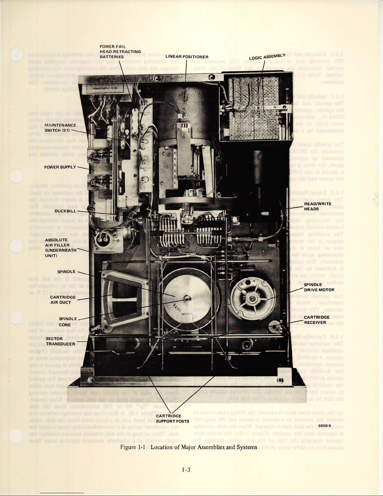
Figure I-I illustrates the locations, and the subsequent
of
paragraphs describe the functions
is
assemblies and systems.
I-I
each
of
the major
Page 7
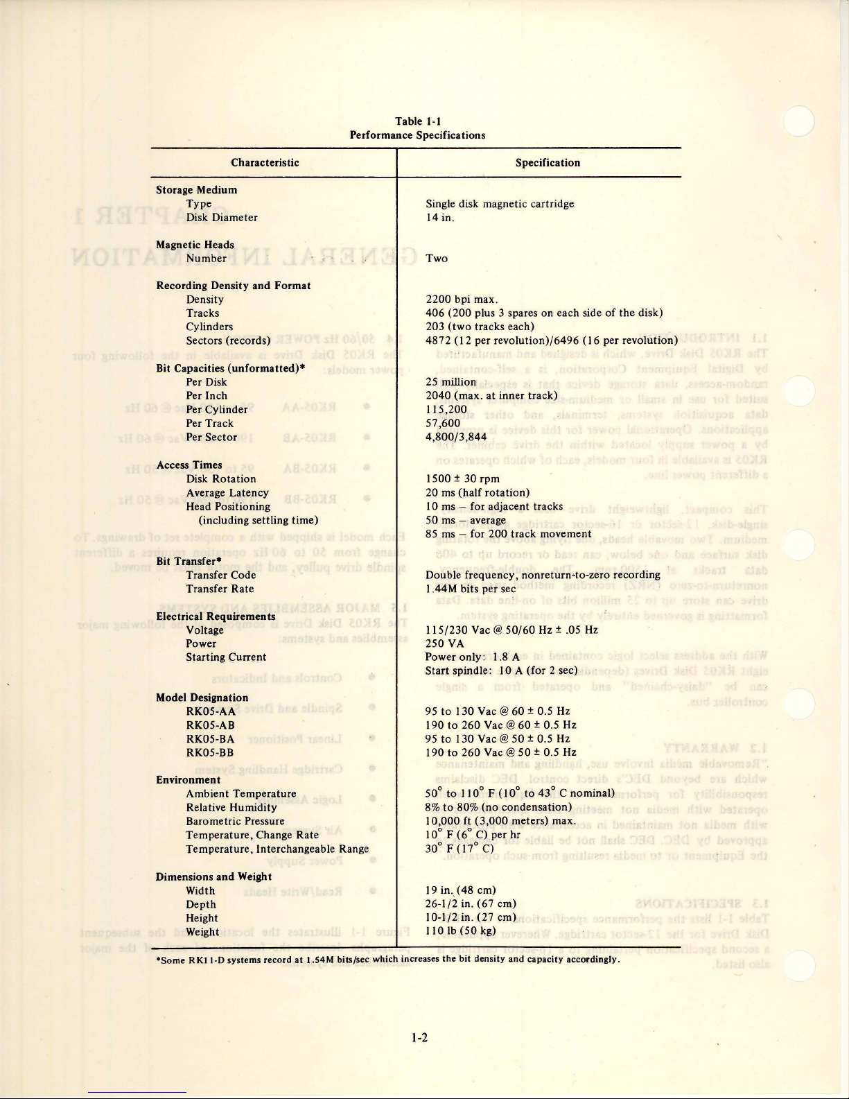
Table
1-1
Performance Specifications
Characteristic
Storage Medium
Type
Disk Diameter
Magnetic Heads
Number
Recording Density and Format
Density
Tracks
Cylinders
Sectors (records)
Bit Capacities
(unformatted)·
Per Disk
Per Inch
Per Cylinder
Per Track
Per
Sector
Access Times
Disk Rotation
Average Latency
Head Positioning
(including settling time)
Transfer·
Bit
Transfer Code
Transfer Rate
Specification
Single disk magnetic cartridge
14 in.
Two
2200 bpi max.
406
(200
203
(two
tracks each)
4872 (12 per revolution)/6496
plus 3 spares on each side
of
the disk)
(16
per revolution)
25 million
2040 (max. at inner track)
115,200
57,600
4,800/3,844
1500 ± 30 rpm
20 ms (half
rotation)
10 ms - for adjacent tracks
50 ms - average
~
85 ms
for 200 track movement
Double frequency, nonreturn-to-zero recording
1.44M bits per sec
Electrical Requirements
Voltage
Power
Starting Current
Model Designation
RK05-AA
RK05-AB
RK05-BA
RK05-BB
Environment
Ambient Temperature
Relative Humidity
Barometric Pressure
Temperature, Change Rate
Temperature, Interchangeable Range
Dimensions
and
Weight
Width
Depth
Height
Weight
.Some
RKII-D
systems
record
at
I.S4M
bits/sec
which
115/230
250
VA
Vac @
50/60
Power only: 1.8 A
Start spindle:
130 Vac @ 60 ± 0.5
95 to
190 to 260
95
to
130 Vac @ 50 ± 0.5
190
to
50°
to
8%
to
80% (no condensation)
lOA
Vac@60±
260 Vac @ 50 ± 0.5
110° F (10°
10,000 ft (3,000 meters) max.
10° F (6° C) per hr
30° F (17° C)
19
in.,( 48 cm)
26-1/2 in. (67 cm)
10-1/2 in. (27 cm)
110
Ib
(50
kg)
increases
the
bit
density
and
Hz
± .05
(for 2 sec)
Hz
0.5
Hz
Hz
Hz
to
43° C nominal)
capacity
accordingly.
Hz
1-2
Page 8
MA
INTENANCE
SWITCH (S1)
POWER SUPPLY
POWER-
FAIL
HEAD-RETRACTING
BATTERIES
LINEAR
POSITIONER
LOGIC ASSEMBLY
READ/WRITE
HEADS
ABSOLUTE
AIR
FILLER
(UNDERNEATH
UNIT)
SPINDLE
CARTRIDGE
AIR
DUCT
SPINDLE
CONE
SECTOR
TRANSDUCER
CARTRIDGE
SUPPORT POSTS
CARTRIDGE
6858
-6
Figure
1-1
Location
of
Major Assemblies and Systems
1-3
Page 9
1.5.1 Controls and Indicators
The controls and indicators (Figure 1-2) required for
normal
cabinet. Table 1-2 describes
operation
are located
the
on
the
function
front
of
of
each control
the drive
or
indicator.
1.5.2 Spindle
The spindle and drive system (Figure 1-3)
the
spindle, spindle drive
50/60
Hz, split-phase ac
drive belt)
maintained by a tension spring anchored
The spindle speed
measures
increases
speed,
the
is
placed in
the
motor
1.5.3 Linear
The linear positioner (Figure
motor,
positioner transducer. To move
the
recording disk, dc current
bobbin-wound armature (Figure
and
Drive
is
motor,
and
the
recording disk. A
motor
transfers
to
the
spindle drive pulley. Belt tension
is
electronically tested by a circuit
the
INDEX PULSE interval. When
to
approximately 45 ms, indicating an unsafe
drive
is
cycled down.
the
LOAD position, ac power
and
the
spindle coasts
If
to
the
a halt.
torque
to
the
RUN/LOAD switch
is
rerr.oved from
Positioner
I-I)
the
carriage,
consists
the
read/write heads, and
the
read/write heads across
14)
is
of
of
applied
the
composed
(via
of
the
baseplate.
that
the
interval
the
linear
the
linear
to
the
linear motor.
The resulting magnetic field reacts with a permanent
magnet in
into
depending
armature. This
is
fastened
heads, which are
surface
Any carriage movement
transducer, which
carriage. The transducer
logic
the
servo logic
or
force it
of
the
to
determine
the
motor
out
upon
the
motion
to
the armature.
attached
disk.
the
to
govern
housing to either pull
of
the
permanent magnetic field,
polarity
is
of
the
is
transferred to
As
to
the
is
detected
located on
output
current applied
a result,
carriage, move across
by
the
is
used with
cylinder position
the
speed
of
carriage travel.
the
armature
the
carriage, which
the
read/write
the
linear positioner
underside
the
of
the heads, and in
to
the
the
of
the
control
1.5.4 Cartridge-Handling System
The cartridge-handling system (Figure
cartridge receiver,
opener, a duckbill, and
normal
operation,
two
receiver lifting cams, an access
two
cartridge support posts. During
the
plastic cartridge
I -Sa) consists
is
located only
of
door
by
the duckbill and support posts. The cartridge receiver
merely
guides
the
cartridge
the
duckbill and
to
rotate
freely
the
disk by magnetic coupling
As
the
drive
elevate
coupling
is
opener
access
the
at
inserted
contacts
door
on
front
receiver
the
disk
into
the
to
allow
support
door
the
into
position
posts, allowing
the
spindle. The rotating spindle drives
at
the
is
opened,
to
a slanted position and
hub
is released. When
receiver (Figure 1-5b),
rear
of
the
entry
of
the
read/write heads.
to
the
disk hub.
the
lifting cams
the
top
cover, opening
be picked
recording disk
the
disk cartridge
the
access
up
by
rotate
to
magnetic
door
the
As
the
drive front
the operating position , and
engages the disk hub. When
position,
the
and removes
cartridge receiver should
door
is
closed, the cartridge is low ered
the
magnetic coupling again
the
cartridge
is
plastic case depresses the cartridge-on switch
the
no-cartridge interlock
not
hold
the
cartridge tightly.
1.5.5 Logic Assembly
The logic assembly (Figure
of
the
is
portion
Three
of
disk drive, holds eight printed circuit cards.
these cards contain
read/write circuits . Two cards contain
One card is
logic.
electronics with
components, while
the
the
positioner and
the
I-I),
cable
connector
remaining
located in
the
system logic and
the
that
other
two
cards contain
interface cables and terminators.
1.5.6 Air System
The air system (Figure 1-6) consists
absolute filter, plenum chamber, and
As
the
blower rotates, unfiltered air
prefilter, where it
prefiltered air
and
into
the
is
then
plenum.
is
purged
circulated
From
there,
absolute filter (where minute
up
the
cartridge air
Cooling air
plenum,
through
1.5.7
through
the
Power Supply
from
front
duct,
the
absolute filter
the
linear positioner. Exhaust air exits
grill
of
the
The power supply (Figure
portion
the
230V, 50 or 60
of
the
disk drive, furnishes all
drive. The power supply can operate
Hz
line voltage
of
the
prefilter, blower,
the
cartridge air
is
drawn
of
large dust particles. The
through
the
air passes
the
contamination
and
into
the
is
also shunted,
drive.
I-I),
located in
the
with a liS V or
input
.
1.5.8 Read/Write Heads
There are
Disk Drive. One head functions
recording disk and
a
mounted'
unloaded, on a plastic cam block
1-7). Flat cantilever springs connect
the
RUN mode,
two
ramp-loaded read/write heads in
the
other
on
on
suspension arms
that
head-support tailpieces. When
the
positioner moves
on
the
top
the
bottom.
rest, when
of
the
the
suspension arms
the
drive is placed in
the
heads forward
duckbill (Figure
cylinder zero. When the entire head slider pad has passed
the
edge
of
the
disk, a ramp
down
the
edge
of
the
(loading)
the
heads
the
heads close
"fly"
80
to
surface (Figure 1-8). A film
disk and
the
disk. Thus, as long as
heads remain
the
the
head acts as a force away from
cantilever spring is a counterbalancing force toward
the
at
a relatively
disk surface.
on
the
suspension arm slides
plastic cam block,
to
the
disk surface. When loaded,
100 micro inches from
of
air (air bearing) between
disk
rotation
constant
remains
distance away from
thereby
to
in
the
operating
condition
the
. The
right rear
the
positioner servo
interfaces
the
chassis-mounted
the
duct.
through
the
logic assembly
through
the
is removed),
disk cartridge.
by
the
the
left rear
dc voltages for
the
RK05
surface
of
the
The heads are
the
heads are
to
the
toward
moving
the
disk
the
the
disk, while
the
constant
the
14
Page 10
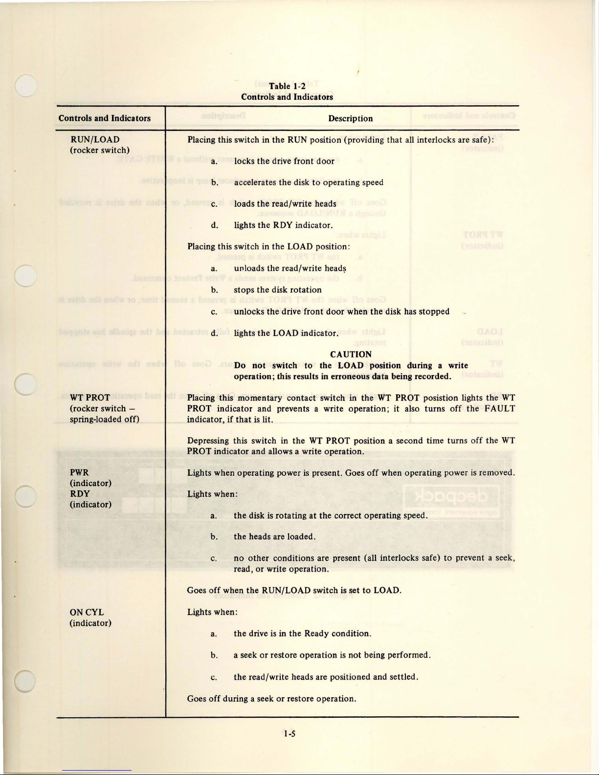
Table 1-2
Controls and Indicators
Controls and Indicators
RUN/LOAD
(rocker switch)
WTPROT
(rocker switch spring-loaded off)
Description
Placing this switch in the RUN position (providing
a.
locks the drive front door
to
b. accelerates the disk
operating speed
c. loads the read/write heads
d. lights the
RDY indicator.
Placing this switch in the LOAD position:
a.
unloads the read/write
b.
stops the disk rotation
c.
unlocks the drive front door when the disk has stopped
d.
lights the LOAD indicator.
head~
CAUTION
Do
not
switch
operation; this results
Placing this momentary contact switch in the
to
the LOAD position during a write
in
erroneous data being recorded.
WT
PROT indicator and prevents a write operation;
indicator, if
that
is
lit.
that
all interlocks are safe):
PROT posistion lights the
it
also turns off the FAULT
WT
PWR
(indicator)
RDY
(indicator)
ONCYL
(indicator)
WT
Depressing this switch in the
PROT position a second time turns
PROT indicator and allows a write operation.
is
Lights when operating power
present. Goes
Lights when:
a. the disk
is
rotating at the correct operating speed.
b. the heads are loaded.
c.
no
other
conditions are present (all interlocks safe)
or
read,
Goes off when
write operation.
the
RUN/LOAD switch is set
Lights when:
a.
the drive is in the Ready condition.
Goes
b. a seek
c.
off
during a seek
or
restore operation
is
not being performed.
the read/write heads are positioned and settled.
or
restore operation.
off
when operating power
to
LOAD.
off
is
removed.
to
prevent a seek,
the
WT
1-5
Page 11

Table
1-2
(Cont)
Controls and Indicators
Controls
FAULT
(indicator)
WTPROT
(indicator)
LOAD
(indicator)
WT
(indicator)
RD
(indicator)
and
Indicators
Description
Lights when:
a. erase
b.
off
Goes
through a
Lights when:
a.
b.
Goes
off
when
recycled through a RUN/LOAD sequence.
Lights when
rotating.
Lights when a write operation occurs. Goes
terminates.
Lights when a read operation occurs. Goes
or
write current
the
linear positioner transducer lamp
when
the
WT
PROT switch
RUN/LOAD sequence.
the
WT
PROT switch
the
operating system sends a Write Protect command.
the
WT
PROT switch
the
read/write heads are fully retracted and
is
present
is
pressed.
without
is
pressed,
is
pressed a second time,
off
a WRITE GATE.
is
inoperative.
or
when
the
off
when the write operation
when the read
the
drive is recycled
or
when
the
spindle
operation
h~s
terminates.
drive
is
stopped
g5ecpa£~
..
.
~.
. .
...
.
RUN
LOAD
Figure ]-2 Controls and Indicators
1-6
WTPROT
ROV
ONCYl
"\'IR
FAULT
......
111111
WT
PROT LOAD
WT
RO
11111111
Page 12

TENSION
SPRING
DRIVE
BELT
SPINDLE
PULLEY
DRIVE
TRACK
MOTOR
POSITION
SCALE
Figure
LINEAR
(UNDER
1-3
Spindle and Drive System
TRANSDUCER
CARRIAGE)
HEAD
ADJUSTMENT
SCREWS
LOWER
CLAMP
UPPER
CLAMP
READ/WRITE
HEAD
SCREW
HEAD
SCREW
HEADS
6544-4
MOTOR
(PERMANENT
HOUSING
MAGNET
INSIDE)
ARMATURE
Figure
CARRIAGE
1-4
Linear Positioner
1-7
CARRIAGE
SLIDE
DUCKBILL
6858
-5
Page 13

LIFTI
NG
D
RIVE
FRONT DOOR
MOTOR
a.
Cartridge Removed
DOOR OPENER
CARTRIDGE
AIR
CARTRIDGE
ACCESS
DOOR
DUCT
b.
Cartridge Inserted
Figure 1·5 Cartridge Handling System
1·8
6858
-'
Page 14

CARTRIDGE
AIR
DUCT
ABSOLUTE
FILTER
PREFILTER
CP-0272
Figure 1-6 Air System
1-7
Figure
Head Loading
1-9
Page 15

Figure
1-8
Relationship
The
DOWN (UPPER) HEAD
throughout
the
UP (LOWER) HEAD faces up. These designations were
created
the
computer
to
describe heads loaded
is
so-called by convention
industry because it faces
onto
a multisurface
20) cartridge.
The recording device (read/write head)
ferrite core with an air gap. As current flows
is
a coil-wound
thwugh
of
Disk Head, Disk, and Contaminants
coil,
the
induced flux magnetizes
down
;
passing
under
the
current direction in the coil is reversed , a flux reversal
(10
or
recorded on
the
previously-recorded flux
the
current in
head . Any flux reversal
surface produces a pulse.
the
08-0884
the
gap. During a write
surface
operation,
of
when
disk. During a read operation,
pattern
on
the
disk induces
on
the
recording
the
disk
the
is
the
1-10
Page 16

CHAPTER
2
2.1 UNPACKING AND INSPECTION
The
RKOS
Disk Drive can be shipped in a rack as an integral
of
part
shipped in a rack,
installation location and unpacked as follows:
a system
I. Remove
2. Remove
3.
4.
S.
6.
or
in a separate container.
the
rack should be positioned in the final
the
shipping brackets from
by
removing
lowest drive.
bracket and latch molding
drive.
Do
not
pull
the
Slide
the
and pull
sides
of
back
onto
screws.
Slide
the
access
directly above
two
these
Repeat
Remove
screws
brackets
the
snap-on bezel beneath
the
screws attaching
CAUTION
use
the
drive
front
drive
out
from
the
drive
out
about
the
shipping brackets
the
drive.
Attach
the
drive .with
lowest drive
to
the
shipping brackets on
it
shipping brackets.
Steps 3 and 4 for each drive in
the
drive
that
attach
to
the
baseplate (Figure
out
and remove
bottom
the
three internal shipping
to
both
door
rack.
3 inches from
the
the
shipping bracket
far enough
the
cover and remove
If
the
drive is
the
drive
the
shipping
sides
of
handle
to
the
rack
out
from
latch molding
to
gain
the
drive
screws from
the
rack.
2-la).
the
the
the
the
INST
7.
If
RKOS
drives are "daisy-chained"
drives in a multidrive installation, arrange
RKOSs
the bus
and
carried by
possible, all
bus
cables between their
2-2).
Remove
8.
mounting screw and shipping strap from
linear positioner (Figure
shipping strap upward and replace it on
linear positioner, making sure it
secured.
Retain all packing material for possible
9.
reshipment. Inspect
damage. Report any damage
to
In
10.
reshipment, replace
shipping strap in
this unpacking and inspection procedure when
the
consecutively at the controller end
to
avoid
DC
LOW interface lines, which are
the
RK03s.
RKOSs
by
RK03s must be connected
the
drive
Digital
Equipment
the
case
of
drive is reinstalled.
ALLATION
interruption
If
that
106 connections (Figure
top
the
Corporation.
RKOS
Disk Drive relocation
the
the
shipping position; repeat
of
this arrangement
are separated
cover and remove
2-lb).
drive for possible
to
shipping brackets and
with
the
by
Turn
the
carrier and
RK03
AC
is
on
separate
is
tightly
the
of
LOW
not
not
the
the
the
the
the
or
CAUTION
Do
not
operate drive with shipping
brackets
attached.
If
the
drive is shipped in a separate container, use care while
unpacking it. Do
unreasonable impact.
2-1
not
drop
the
drive
or
subject it
to
Page 17

SHIPPING
BRACKET
BRACKET
SCREW
SHIPPING
STRAP
SHIPPING
a.
Shipping Brackets
MO
UNTING
SCREW
BRACKETS
P2
LINEAR
POSITIONER
Figure
b. Shipping Strap
2·1
Shipping Bracket and Shipping Strap Locations
2-2
Page 18

INTERFACE CABLE
JOG
2.2 MECHANICAL
If
the
RK05 Disk Drive
the
chassis slides should first be installed
2-3). The disk drive should be
as follows:
(If
INSTALLATION
is
to
be installed in an existing rack,
mounted. on
necessary, refer
Figure 2-2 RK
AND
in
to
the RK05
II
CHECKOUT
the
rack (Figure
the
chassis slides
C
or
Option
RK
Configuration Dwg. No. D-OC-RK05-0-15 for detailed
mechanical specifications
I.
Install cabinet stabilizers before
drive, unless
to
prevent tipping when
of
a muItidrive installation.)
the
weight
of
the
rack
the
drive
mounting
is
sufficient
is
the
fully
extended.
2. Pull
the
extended
chassis slides
position.
out
until
they
lock in
the
II
D Interface Cable Installation
3. Slide
the
locks.
4. Remove
screws
that
brackets
5. Remove
mounting
linear positioner (Figure
shipping strap upward and replace it
linear positioner. Pull
as possible
1-7) and confirm
return
the
2-3
drive
onto
the
chassis slides until it
the
drive
attach
to
the
baseplate (Figure
the
drive
bottom
cover and remove
the
three
internal
top
cover and remove
2-la).
screw and shipping strap from
2-1
b).
Turn
the
heads forward as far
without
heads
going
that
the
to
the
home position.
off
the
ramp
batteries (Figure
the
shipping
the
the
the
on
the
(Figure
I-I)
Page 19

BOTTOM
PAN
L.
H. RAI
L-.
. r
to.44
r
42.22
7L
~
1.47
317T
21.22
T
10.72
1
r-;--
"..;-
11
. :
~
j
:1
:1
:1
I
,
,
---
8.
If
RKOS
RACK
r
-
rn
[]
ODD.
0000
CCC.
0000
--,-
-+,
1.1-- R.H.
:
--t
!'!.
I:
r-- RKOS
RA
IL
CHASSIS
SLIDE
--
drives in a multidrive installation, arrange
RKOSs
the
and
carried by
possible, connect all
on
cables between their
2-2).
If
the
9.
RK
interface cables as follows:
a. Remove
b.
I:
rn
000.
0000
I:
ill
DOO.
0000
:
(fiRST
HOLE
,
44
j
-
--
r·
,
-
CP-0273
c.
d. Place
10.
If
the
RKll-D
either as described in Step 9, above, (which is
preferable)
drives are daisy-chained with RK03
consecutively at
bus
to
avoid
interruption
DC
LOW
interface lines, which are
the
RK03s.
the bus by RK03s by means
drive
is
to be connected
ll-C
or
RK
II-D
the
Route
the
interface cables through
prefilter opening and reinstall
and frame so
slot on
Route
fold
fold in
to
the
side
the
cables over
them
as
the
cable retaining bracket over
the
cables and fasten
the
chassis.
drive
is
to
be connected
controller, install
or
as
follows:
the
controller end
of
If
this arrangement
RKOSs
prefilter and frame.
that
indicated in Figure 2-4.
that
J06
connections (Figure
to
controller, install
the
cables fit
of
the
frame (Figure 2-4).
the
to
the
interface cables
the
the
AC
LOW
not
is
not
are separated
of
separate
other
than
the
the
the
filter
into
the
prefilter and
the
the
bracket
an RK
ll-C
of
an
or
Figure 2-3 Chassis Slide Mounting
6. Inspect P2 (Figure 2-1) and the spindle pulley
to
ensure
for
two
115
jumper,
The operating frequency
spindle pulley.
7. Check
are
cable card
assembly.
system,
daisy-chain, ensure
card (Dwg. No.
interface card position.
that
the
the
input
power
jumpers,
Vac operation.
the
bent
the
the
supply is configured for
logic assembly
or
broken , and
into
card position 7
If
there
or
if this
drive
is
configured properly
to
be used.
supply
If
P2 contains only one
then
is
only
is
the
that
RKOS-O-2)
If
is
configured for
is
stamped on
to
ensure
plug
or 8 of
one
last drive
an M930
is
in
P2 contains
230
Vac.
the
that
no pins
the
interface
the
logic
drive in the
of
the
terminator
the
unused
2-4
Fold
the
a.
through
at
2-4).
b. Hold
the
To avoid random errors, confirm
II.
grounding strap
base plate and
mounted
Confirm
place.
Configure the
12.
valid drive
Plug
13.
the
receptacle.
interface cables and
the
slot just below
the
rear
of
the
the
cables in position and replace
bottom
that
power cord
cover.
is
firmly in place between
the
chassis, and
securely and in
all connectors are securely in
M7700 select switch
(Paragraph 3.2.2).
into
route
them
the
prefilter
drive cabinet (Figure
that the
the
that
brushes are
the
proper plane.
to
address a
the
switched ac line
Page 20

A = SINGLE
B =
DOUBLE
FOLD
FOLD
i
__
B_b
A
B
A
Figure
2-4
RK8/E Interface Cable Installation
2-5
Page 21

14. Turn the processor keyswitch
power
to
the
drive.
15
. Check
2.3
CARTRIDGE HANDLING PRACTICES AND
that
heads are
the spindle
not
bent
or
is
dirty.
ON
to
apply
clean, and that the
PRECAUTIONS
To obtain maximum performance and high reliability from
the RK05 Disk Drive, the following precautions and
cartridge-handling practices must be observed:
1.
Store cartridges in a clean, dry area away from
direct sunlight. Do not expose cartridges
heat. They may be stored on edge
however, stacks
should be avoided. Do
the
plastic cartridge cases. Do
cartridges on
of
more than 3
top
of
not
place heavy items
computer cabinets
or
or
4 cartridges
not
to
stacked;
on
store
or
in
places where dirt can be blown by fans into
cartridge interiors.
2. Whenever a cartridge
in a plastic bag
3.
Professional cartridge disassembly and cleaning
is
to
exclude dust
not
in a drive, enclose it
or
dirt.
is required every six months; however, disks
should be cleaned whenever they are
sively dirty,
is
encountered. In such instances, a disk-
cleaning service, listed
or
when a high transient error rate
by
Corporation, should be contacted
Place stiff cardboard
4.
the
molded
cartridge without
placed .
on
fram~
any
at
the front edge
u~jng
other
part
Or
plastic labels only in
any adhesives. Labels
of
interfere with the drive operation
contamination into the drive
the
cartridge.
5.
Allo~
the temperature
of
Digital Equipment
at
the
cartridge may
or
the
the cartridge to
once.
of
the disk
or
introduce
interior
exces-
of
become stabilized with the room temperature
If
before using the cartridge.
to
exposed
outside temperature extremes,
cartridges are
or
if
the temperature differential between drive and
cartridge
stabilization period
exceeds 20° F, a two-hour
is
necessary.
Although cartridges recorded on RK03s and
6.
RK05s are fully interchangeable, allow them
stabilize before new data
is
recorded on them.
Data interchangeability between drives
guaranteed if
not
exceed 30° F (17° C), even though a
the
temperature difference does
is
to
only
specific drive/cartridge combination may
of
50°
operate over a temperature range
110° F
(l00
to
43° C).
7. Keep the spindle hub clean and free
fr~m
to
nicks
and burrs to ensure reliable cartridge operation.
Because the hub
expose it
the
to
mounting surface. Periodically inspect
coupling hub
is
slightly magnetic, do
metal chips
on
the
that
could adhere
bottom
of
not
to
the
the disk
cartridge for dirt, metal chips, plastic chips in
cone, etc.
8. A sustained tinging, scratching, or rumbling
sound
(not
to be confused with spindle ground
is
brushes) that
the result
contact may occur if the cartridge
properly seated
on
the spindle, if excessive
contamination has built up in
the
cartridge,
defective.
or
If
this sound
if the cartridge
is
drive immediately to avoid damage
of
head-to-disk
is
not
the
or
interior
the
of
drive
heard, shut down the
to
the
read/write heads. Remove the disk cartridge
and examine
dirt.
If
not
reuse
the
heads for damage
necessary, clean
the
cartridge without first checking it
or
replace the heads. Do
or
excessive
for surface damage.
CAUTION
NEVER CYCLE A
BAD
CARTRIDGE
THROUGH AN INSTALLATION OF
SEVERAL DRIVES. This practice can
ruin all the read/write heads
or
contaminate all drives in a multidrive
installation, which will, in turn, damage
all
other
cartridges run in these drives.
of
9. Always keep the front door
and keep all covers
of
entry
2.4
CARTRIDGE PACKING AND SHIPPING
atmospheric dirt or dust.
on
to
the drive closed
prevent unnecessary
Data recorded on disk cartridges may be degraded by
exposure
contact with the disk surface .
in
against possible exposure
physical separation from the magnetic source
the
cargo hold
to
any sort
of
small magnet brought into intimate
If
cartridges are
of
an aircraft, precautions are necessary
to
magnetic sources. Because
to
be shipped
is
the best
is
2-6
Page 22

protection
cartridges should
box.
protect
encountered
unnecessary
2.5 NORMAL OPERATING
All drives in a multidrive system must have operating
applied even when
unused drives should
RUN/LOAD
IMPORT ANT:
DRIVES EQUIPPED WITH A POWER
DO
OPERA TION
AN
INDIVIDUAL
Because
drives
disables all
controlled
against accidental erasure
be
packed
This
amount
against
to
of
separation should be
any
magnetic sources likely
during
transportation,
ship cartridges in specially shielded boxes.
the
be
NOT
switch in
USE
ON
THE
the
EARLIER
ON/OFF
TO REMOVE OPERATING POWER FROM
DRIVE.
the
DC LOW interface signal
in
a multi drive system, a
the
drives in
by
a processor keyswitch, all drive
of
a cartridge,
at
least three inches within
adequate
making it generally
PROCEDURES
drive
is
not
in use. In
addition,
left write-enabled, and with
LOAD position.
MODEL
RKOS
ON/OFF
SWITCH,
SWITCH DURING SYSTEM
is
common
power
loss in
anyone
the
system.
If
the
drive power
ON/OFF
the
to
power
DISK
to
drive
switches should be left ON; however, all RUN/LOAD
switches should be set
to
LOAD before system power
removed.
2.5.1 Cartridge Loading
The procedure for cartridge loading
1.
Set
the
RUN LOAD switch
LOAD and observe
is
that
as follows:
on
all drives
the
LOAD
indicator
lights.
to
be
the
all
to
If
the
LOAD
door
to
is
force
front
2.
front
attempt
Open the
insert a clean, operable disk cartridge fully
the
cartridge receiver. DO NOT TWIST
FORCE
THE
INSERTION!
Close
the
3.
front
RUN/LOAD switch
4. Wait for
light,
read,
2.5.2 Cartridge
the
the
drive
or
write operations.
Unloading
The procedure for cartridge unloading
I.
Set
the
is
observe
RUN/LOAD switch
that
approximately
2.
3.
4.
will light.
Open
the
drive
the
disk cartridge.
If
another
drive
front
door
of
atmospheric dirt
Store
the
cartridge in a clean plastic bag.
cartridge
is
CAUTION
indicator
locked.
the
door
is
In
front
of
not
lit,
this case,
door
the
CARTRIDGE
door
of
the
drive
to
RUN.
RDY and ON CYL
is
now
ready
is
as follows:
the
RDY
indicator
30
seconds,
front
to
or
the
door
and
is
not
loaded, close
prevent unnecessary
dust.
the
do
open.
drive
indicators
to
perform
to
goes
LOAD
gently
and
drive
not
and
gently
into
OR
DURING
set
the
to
seek,
LOAD and
out.
After
indicator
withdraw
the
entry
2-7
Page 23

3.1
GENERAL
The flexibility achieved with
the
eight-position address select switch permits
Disk Drive
systems. hi'
drives can be
RK
Il-D
connected.
Interface, cable conne.
to
card position 7
positions are parallel-wired so
daisy-chained in a multidrive configuration;
position 7
position 7
card position 7 is used
used for
system, an M930
unused interface card position; if there
drive in
the
M930
position. The
M930
approximately +0.5 Vdc, and a negation,
approximately +3.5 Vdc.
to
be connected
the
RKI1-C
seri~lly
system,
or 8 of
or 8 of
output
the
system, only
terminator
terminator
up
ction
or 8 of
the
the
succeeding drive, etc. (By convention,
for
signals.)
t'erininatorcard
card in
interfa'ce signal levels are determinea
card. An assertion,
the
address select logic and
to
a variety
and
RK8/E
connected
to
eight drives can be serially
of
the
the
electronic module. These card
first drive
input
If
there
the
last drive
systems,
to
a single bus; in
RK05 Disk Drive
that
several drives may be
is
connected
signals; card position 8
is
only one drive in
must be installed in
is
on
the
the
unused interface card
or
the
RK05
of
computer
up
to
is
made
that
is, card
to
card
more
than
bus must have
by
logic
I,
or
logic
0,
four
the
is
the
the
one
the
is
is
CHAPTER
INTERFACE
3.2.2 , Select
BUS
SEL DR
conjunction
eightcposition address select switch
determine
of
one
a.
b.
(4Iines)
0/
A/E, 1
/B/F,
2/C/H, and
with
the
RK II-D interface line and an
the
drive address assignment and selection by
the
following
With a logical 0 on
selection circuit is configured
four selection lines as a linear set.
particular drive, only
internally connected (via positions
of
control
places a logical I
line remains
data transfer
With a logical I
selection
selection lines as a binary-encoded set.
a drive,
code, which
on
translated
to
switch positions.
two
methods:
the
the
address seleCt switch) '
logic.
To
select a drive,
on
the
at
logi~al
or
control
on
the
is
configured
th
,e controller places a 3-bit binary
corresppnds
these select lines. This binary code
by
a three-line-to-eight-line
activate only
one
of
3/D/J L operate
on
the
M7700 card
RKII-D
one
I
operation.
RKII-D
the
line,
the
M7700
to
decode
In
of
the
four
lines is
0
through
to
the
drive
the
controller
desired select line. This
throughout
to
decode
to
the
eight address select
the
entire
line,
the
M7700
the
To
select
drive address,
is
decoder
3
in
to
the
a
3
four
then
3-1
Figure
the
bus signals, operate according to negative logic;
asserted low. Appendix A contains a glossary
backplane connections.
3.2
3.2.1
This line (BUS RK
the
controller type. A logical
controller
an RK
drives
controller is an
illustrates and
function
INPUT INTERFACE LINES
address select logic
of
each
RKII-D
is
not
an
ll-C
or
an
RK8/E,
on
a single bus), while a logical I indicates
RKII-D.
the
following paragraphs describe
interface
II-D
RKlI-D
line. The signals listed, being
L) transmits a signal
to
0 on this line indicates
(thus,
both
operate with a particular
the
of
which
that
controller
control
they
are
of
RK05
configures
that
the
is
either
only four
that
the
3.2.3
Cylinder Address
BUS
CYL ADD 0 L through BUS CYL ADD 7 L determine
the
cylinder position
move
the
heads
to
corresponding 8-bit binary code
202
through
to
position
code remains
Acknowledged
from
the
3.2.4
Strobe
BUS
STROBE L transmits a signal
Address
the
Strobe line, only
Restore signals are fully settled on their respective lines.
3-1
).
10
the
heads at
on
or
drive (Paragraph 3.3.3).
or
Restore line. The controller places a logical I
(8
lines) ,
of
the
read/write heads. In
a desired cylinder,
on
the
These lines are gated
the
selected cylinder. The binary
the
lines until either
the
Address Invalid signal is
that
after
the
Cylinder Address
the
controller places a
lines (valid codes=O
by
the
Strobe signal
the
gates
the
order
to
Address
returned
Cylinder
on
or
the
Page 24

Ir
IA.I
oJ
oJ
0
Ir
I-
~
u
2
0
Ir
10-
I-
:::l
Q.
Z
-
II')
0
:10:
Ir
CONTROLLER
•
Ir
IA.I
oJ
oJ
0
Ir
I-
~
u
0
II-
:::l
Q.
I-
:::l
0
II')
0
:10:
Ir
BUS
BUS
BUS
BUS
BUS
BUS
BUS
BUS
BUS
BUS
BUS
BUS
BUS
BUS
BUS
BUS
BUS
BUS
BUS
BUS
BUS
BUS
BUS
BUS
BUS
BUS
BUS
BUS
BUS
BUS
BUS
BUS
BUS
BUS
8US
BUS
BUS
BUS
RKt1D-L
SEL
DR
f/A/E
SEL
SEL
SEL
CYL
CYL
CYL
CYL
CYL
CYL
CYL
CYL
STROBE
HEAD
WT
WT
WT
tlB/F L A 07
DR
DR
21C/H
DR
3/D/J
ADD
ADD
ADD
ADD
ADD
ADD
ADD
ADD
L B
SELECT
PROTECT
DATA
GATE
RESTORE
RD
GATE
L B
FILE
READY
R/W/S
ROY
ADDRESS
ADDRESS
SEEK
INCOMPLETE
WT
PROT
WT
CHK
L B
RD
DATA
RD
CLK
L B
CNTR
SEC
SEC
CNTR
SEC
CNTR
SEC
CNTR
SEC
PLS
INDX
PLS
AC
LO
L
LO
DC
L
RK05/HIGH
A 07
A
A
A
A
A
A
A
A
07
07
07
07
07
07
07
07
0
I L
2
3 L
4 L
L
L
L
L
L
5 L A 07
A
A
07
07
6
L
7
L
07
a
L
L
L
L
CLK
L
B
B
A
B
A
07
07
07
07
07
07
B
A
A
A
08
08
08
08
08
L
L
ACCEPTED
INVALID
STATUS
L A
L B 08
L
L
08
L B 08
08
13
L
I
L
2
L
3
L
B 08
A
08
B
08
B
08
L B 08
L
DENSITY
L
B08
B
B
B
08
08
08
UI
J2
K2
L2
M2
K1
01
LI
CI
F1
JI
E1
H1
HI
M2
R2
F2
L2
MI
R1
NI
H2
R2
T2
S2
PI
K1
S2
SI
L1
P2
K2
JI
N2
MI
FI
F2
P2
Figure 3-1 Controller/RKOS Disk Drive Interface Lines and Pin Assignments
3-2
CP
- 0141
Page 25

The Strobe line remains
drive.
Select
the
or
two
Acknowledged
the
from
3.2.5 Head
BUS
SEL UPPER
which
of
controller places a logical I
head, and a logical 0
remains on
the
at
logical I
the
Address Invalid signal
HD
L transmits a signal
read/write heads
on
to
select
the
line
throughout
until
either
the
is
that
determines
is
to
be selected. The
this line
to
select
the
lower head. Either signal
the entire read
operation.
3.2.6 Write
BUS
Protect
WT
PROTECT L transmits a signal
drive write amplifiers
controller places a logical
Set
that
to
prevent a write operation. The
Ion
this line
to
disables
set
the
Protect flip-flop and inhibit the write capability
drive. The Write Protect flip-flop
indicator is
off
and
the
is
operator
also set if
presses
the
the
WT
WT
switch (Paragraph 1.4.1).
3.2.7 Write Data
BUS
WT
DATA & CLK L transmits multiplexed data and
clock pulses
to
and
the
disk drive.
Clock
3.2.8 Write Gate
BUS
WT
GATE L transmits a signal
on
both
the
write and erase
head. The controller places a logical I
to
transmitting
throughout
3.2.9 Restore
BUS
RESTORE L transmits a signal
read/write heads
logical I
STROBE
drive
returns
address register, and moves
Restore line remains
Acknowledged signal
the
write data. This line remains
the
data transmission time.
(RTZ)
at
cylinder zero. The controller places a
on
this line prior
L) signal.
About 2 /1s
an Address Acknowledged signal, clears
the
at
logical I until
is
received by
to
simultaneously
current
in
the
on
this line I
selected write
at
to
position
to
issuing
after this signal
the
Strobe (BUS
is
issued,
heads to cylinder zero. The
the
the
controller.
3.2.10 Read Gate
BUS RD GATE L transmits a signal
read from
line
This line remains
to
the
drive. The controller places a logical I on this
enable
the
Read Clock and Read Data
at
logical I
that
throughout
allows data
output
the
entire read
operation.
Address
returned
upper
or
write
the
Write
of
the
PROT
PROT
turn
/1S
prior
logical I
the
the
the
Address
to
be
lines.
c.
The drive
d.
RUN/LOAD switch
e.
Spindle
f.
Read/write heads are loaded.
front
is
rotating
door
at
is
closed.
is
in
the
the
correct speed.
RUN position.
g. Write Check is false.
or
Seek
3.3 .2 Read, Write,
BUS
R/W /S RDY L transmits a logical I
the
drive
is
in
the
File Ready condition (Paragraph 3.3.1)
is
not
and
performing a seek
Ready/On
operation
Cylinder
to
.
indicate
that
3.3.3 Address Accepted
BUS
ADDRESS ACCEPTED L transmits a
pulse
to
indicate
command
with
has begun. The negative pulse
receipt
the
of
the
present address.
3.3.4 Address Invalid (Logic Address
BUS
LOG ADD INT L transmits a
indicate
that
that
the
drive has accepted a Seek
a valid address and
Strobe signal, even
the
is
generated
if
there is no change from
Interlock)
5-/1s
the
drive has received a nonexecutable Seek
command with a cylinder address greater
the
case,
heads are
as for
3.3.5 Seek
BUS
malfunctio
Seek command is suppressed in
not
moved. The pulse generation time is
the
Address Acknowledged signal.
Incomplete
SIN L transmits a logical I
.p.
in
the
drive did
not
allow
to
the
5-/1s
command
about 2 /1S
negative pulse
than
202.
the
drive and the
indicate
seek
operation
negative
execution
after
For
this
the
same
that
some
to
to
be completed. This line remains low until a Restore
is
command
switch
received
to
LOAD and
3.3.6 Write Protect
BUS
WT
PROT STATUS L transmits a logical 1
that
the
write capability
protected). When this line
indicator on
1.4.1
).
or
the
then
back to RUN.
operator
sets
the
RUN/LOAD
Status
of
the
drive
is
inhibited (write
is
at logical 1,
the
drive control panel lights (Paragraph
the
to
indicate
WT
PROT
3.3.7 Write Check
BUS
WT
CHK L transmits a logical 1 to indicate
the
following conditions :
3.3
OUTPUT
INTERF
ACE LINES
3.3.1 File Ready (Drive Ready)
BUS
FILE
RDY L transmits a logical I
following conditions :
a. Drive operating power
b. A disk cartridge
is
correct .
is
properly loaded.
to
indicate
the
a.
Erase
or
write current
b.
Inoperative linear positioner transducer lamp.
the
When
commands
indicator
condition
Write Check signal
to
the
drive are suppressed and
on
the
drive
is
temporary,
FAULT indicator by pressing
3-3
control
the
without
is
at
a logical
panel lights.
operator
the
WT
a WRITE GATE.
I,
all external
the
FAULT
If
the
fault
may
turn
off
the
PROT switch. This
Page 26

action, however, causes the
the
WT
PROT switch must be pressed a second time
off
the
WT
PROT indicator (Paragraph 1.4.1).
WT
PROT indicator
to
to
light;
turn
after the last sector pulse and
index slot (unique slot)
transducer.
is
generated each time the
is
detected by the sector
3.3.8 Read Data
BUS
RD DATA transmits read data only (160-ns pulses).
3.3.9 Read Clock
BUS
RD CLK L transmits read clock pulses only (160-ns
pulses).
3.3.10 Sector Address
BUS
SEC CNTR 0 through 3 L indicate which sector is
passing under the read/write heads. The sector address
(4
lines)
is
4-bit binary code derived from the Sector Address counter.
3.3.11 Sector Pulse
BUS
SEC PLS L transmits a
2-p.s
negative pulse each time a
sector slot passes the sector transducer. The index slot
(unique slot) is suppressed in this line and is transmitted
on
a separate Index Pulse line.
3.3.12 Index Pulse
BUS INDX PLS L transmits a single
each revolution
of
the disk. The Index Pulse occurs 600
2-p.s
negative pulse for
p.s
3.3.13
BUS
more than 45 ms)
AC
Low
AC
LO L transmits a logical 1 when there
of
the 30 Vac within the drive. When
is
a loss (for
AC
Low occurs, the drive finishes reading/writing the current
sector,
cycle.
completely retracted, the safety relay is de-energized
then
initiates a normal head-retract and unload
If
a total power loss occurs before the heads are
to
retract the heads under battery power (emergency retract).
a
3.3.14
BUS
within the drive drops
is
DC
Low
DC
LO L transmits a logical I when the ±15 Vdc
to
12 Vdc
or
below. When
generated, the safety relay is de-energized
to
heads under battery power (emergency retract).
RUN gate
DC
of
each drive
Low signal from
is
connected to the
anyone
drive in a multidrive system
DC
DC
Low
retract the
Since the
Low bus, a
disables all the drives in the system.
3.3.15 High Density/RK05 L
BUS
RK05 L transmits a logical 1 (indicating high density
only) whenever the drive
is
selected. (All RK05s are high
density.)
34
Page 27

APPENDIX
A
THE
A.I
MOVE FUNCTIONS
1.
STEP - incrementing cylinder seek
2. ALT (Alternate) - an incrementing seek from
3.
OSC - oscillate between 0 and
4. RAND - random cylinder seek.
5. Drive Selector - selects
6. RUN - enables all move functions.
7. RTZ - forces a zero recalibrate.
8.
FOR/REV
- selects
the
the
the
drive
initial drive motion
RK05-TA
to
limit and a.high speed return.
the
cylinder address selected.
cylinder address selected
number
selected on
in
the
step and alternate.
OFF-LINE
(not
affected
M7700 module in
by
the
TESTER
FOR/REV).
RKOS
.
9. Cylinder Address - selects any cylinder address from 0
INDICATORS
1.
Address invalid,-
2.
Seek incomplete - excess time
3.
Power
on
-
cyli~der
indicatespow'~r
address set
to
perform
is
applied
up
to
an illegaladdress; i.e., > 202.
the
seek.
to
the
drive.
A·I
to
202.
.
0
Page 28

A.2 WRITE FUNCTIONS
1.
*Write sector - selects a sector (from sectors 0 through 9 only) to write
"All"
simulates a write all. Note: the unit cannot read to check headers.
2.
Head select - selects
thus only one surface
or
enables either the upper
is
written on .
on
and simulates a write data.
or
lower head. Only one head can be selected at a time;
3. *Write
button
causes a write one-shot to write
or
erase on the sector selected
selected).
4. *Constant write - when set, writes continuously on the sector selected ; the write
pressed.
S.
*OC erase - when ON, enables erase on a sector (or sectors) when the WRITE
OFF,
enables writing on a sector (sectors) when the WRITE button
-:-
6. Data bits
-After
the
RKOS·T has
sets a 4-bit data
been
A.3 CONNECTING THE
used
to
RKOS-T
pattem
perform
write
or
erase
OFF-LINE TESTER
to be written on the sector selected.
operations,
the
disk will have
to
is
be
pressed.
1. Disconnect the ac line cord.
a. Remove
b. Check the
them (slot 7
c. Connect a BCII-A cable from slot I
d. Disconnect connector
the
interface cable from the
RKOS
and the tester to ensure that a M930 Terminator module
or 8 of
the
RKOS
11
in the
RKOS.
, or slot 2
or 2 of
RKOS
of
the
RKOS-TA
the tester
Off-Line Tester).
to
slot 7
(logic voltage connector) .
or 8 in
(or
reformatted.
the
RKOS.
the track, if
button
button
is
is
present in one
"All"
is
need
not
be
pressed; when
of
e. Plug one end
f.
Check for proper keying
female connector
of
the tester power cable into the tester.
of
the pins and plug the male connector
of
J I.
g. Connect the remaining connector
h. Reconnect
i. Toggle RTZ
the
ac line cord.
to
initialize and clear all error conditions and proceed with testing.
to
the plug leading
A-2
to
the logic block
of
the power cable into the
of
the
RKOS.
Page 29

RKOS
DISK DRIVE
USER'S
EK·RKOS·OP·OOI
Your
our
What
wri
tten
What features are most useful?
MANUAL
comments
publications.
is
your
general reaction
, etc.?
Is
and
suggestions will help us in
it easy
to
use?
to
this manual? In
our
continuous
your
judgment
effort
is
it
R
to improve
complete,
eader
the
accurate, well organized, well
's C
quality
omments
and usefulness
of
What faults
Does this manual satisfy
it
Does
Would
Please describe
Name
do
you
find with
satisfy
you
your
needs?
please indicate any factual errors
your
position.
the
the
need
manual?
you
think
it was intended
Why?
you
have found.
Organization
to
satisfy?
_________________________________
__
Street
City
______________________________________
__________
_
State
____________
Department
_
Zip
or
Country
Page 30

- - - - - - - - - - -- Fold Here .- - - - - - - - - - -
- - -
--
----
--
--
BUSINESS REPLY MAIL
NO
POST AGE STAMP NECESSARY IF MAILED IN THE UNITED STATES
Postage will be paid by:
Digital Equipment Corporation
Technical Documentation Department
Maynard, Massachusetts
Do
Not
Tear - Fold Here and Staple - -
01754
--
--
-- --
FIRST CLASS
PERMIT NO.
MAYNARD, MASS.
-- --
33
Page 31

DIGITAL EQUIPMENT CORPORATION
Maynard, Massachusetls .
NORTHEAST
REGIONAL OFf iCE: PrInc
23S
Wyman Street.
T
elephone: (61
CONNECTICUr
Menden
240
Telephone
FairfIeld
1
275
Tetephone: (203)
NEW
Rochest
1
30
Telephone: (716) Syracuse
6700 Thompson
Telep
MASSACHUSETTS
Marlbor
One Iron
Marlborough
Te
lephone : (617)·481·
MID-ATLANTIC
REGIONAL OFFICE:
U.S. Aoute
Te
lephone : (
F
LORIDA
Orlando
Suite
Te
leph one: (305)·
GEORGIA
At
lanta
2815
A
tlan
Telephone: (404)·451·7411
NORTH C ARO
Durham/Chapel
Ex
ecutive
37
00
Durham. N
Telephone: (919)
NEW JERSEY
Fairfiel d
253 Passaic
Telephone: (201)·
Metuche
95 M ain
Telephone
EUROPEAN HEADQUARTERS
Dig
ita! Equi
81
route
12
11
Telephone: 42
FRANCE
Digital
Centre
9<1533
Telephone :
GRENOBLE
Di
gital
Tour
16
Rue
38100
Telep
GERMAN
Dig
ital Equi p
MUNICH
8Muenchenl3
Tele p
COLOGNE
5 Koeln 41,
Telephone' 0221-44·40 ·
Teleg
FRANKFURT
6078
Am
T
elephone: 06102·5526
HANNOV
3
Hllnnove
Telephone: 0511-69-70-95
STUTTGART
0·7301 Kemnflt. St
rco·Po
Ma
Telephone '
AUSTR
Diqital Equip me
VIENN
Mar
Telephone: 855
UNIT
Dinit1l
U_K. HE
Fountllin HOllse.
Reading RGI 70N. E
Telephone: (0734)·583555 T
BIRMINGHAM
Mllney
29/3
W<Jrwicksh
Telephone:
BRI
STOL
F,
sh Ponds Road . Fish Ponds
Bri
stol.
Telephone' Bristol 651·0431
EAl/NG
Billo
Telephone' 01·579·2334
EDINBURGH
Sh,el
We
st
elephone: 32705
T
LONDON
Manaljement
43
P<Jrkf'r St . Hol
WC
T
el~hone
MANCHESTER
Arndale HOl.se
Chesler Road. Stre tford.
Telephone-
Walt
ham.
Mass. 021
7)-890-0330/0310 D
Pome
roy
Ave .. Me r iden. Conn.
: (
203)-237
Post Ro ad, Fair field. Conn .
-255-5991
YORK
er
Alfens
Creek
Aoad. Rochester.
461-1700
ROlld,
hon
e: (315).4 3 7
ough
Way
, Mas s 0 1
1.
Prin ce
609
)·452·2940
1~
.
7
001
Lake E
851.4450
Clearview
Place . Su ite 100
ta.
Geor
gia
(3)4()
LIN
Hill
Park
Chap
el Hill
or
th
Carol
·489·334
Ave ,.
227
n
Street.
Met
: (
201)-549·4100/2000
pme
nt Corporation
de r
Aire
Geneva
26
.
S
wit ~er
79
50
Equipment
Sillc -Cidex L225
Rungis, France
68
7-23·
Equipm
ent
Mangin
Du
Gal
Mangin
Grenoble
. Fr ance
hone : (76)·87-56·01 Telel(: 212-32882
FEDER
ment GmbH
, Wallenllteinplatz2
hone
: 0811
·35031
Aachener
rllm , Flip C h
ip
Neu·lsen
burg 2
Forst
llUS Gr
avebruch
ER
r. Podbi elskist
lo· St
rflsse
(0771)·
4:;
IA
nt Corpo
A
iah ilfer
strllsse
1 86
ED KINGDOM
1 Equipment Co .
ADQUARTERS
Butts
Buildlnqs
1 Bi r
minqham
ire . Engla'rM
02\·3
55-5501
En!lland BS16:\HO
n House . Uxbridge Aoad
House.
Craigsh
Loth'an.
Scot
House
born
2B
5PT. Enqland
:
01·405·261
(061)·865·7011 Telex: 668686
ataphone: 617
-844117466
Datilphonc-203·
06430
Dataphone : 716·
Syracus
e. New
·1
593/
7085
Dataphone
752
7400
Tel e
... , 710·347·0348
ton. New
Jersey
lleno
r Dr ive .
Orlllndo
Dataphone:
Datap
A
Blv
F
~irfield
ucht:n. N
hone: 305·859 ·
d
ina
2170
7
7 Dataphone: 919·489·7
.
New
Jersey
·92
80
Dataphone
ew
Jersey
Dataphone
Internationel
land
Telex: 22 683
France
33
Telex'
26840
France
AL REPUBLIC
Tel el(: 524·225
Stf1lsse
311
95 Telex ' 888·2269
Koel n
5-7
Telex' 41·76-
rasse 102
Telex : 922-
uttgar
t
1
·!'">O-65
Tele
x:
rati on Ge s .m.b .H.
13ft
1150
Vienna IS.
ltd
Centre
nt:l
land
elex
8483278
Ad . SuUon C:oldf iel d
Tele. 331-()60
.
E~l ing.
Telex: 22371
iU L,vi
ngston
lan d
Tel ex '
127
113
. Lond on
4/4067 Telex
Mllnch
ester M
06540
New York
06540
8<11
.
54
244.1680
Yor
k 1
3211
: 31
. F
305--859·2360
07006
: 201·227·9200
06840
: 201·548·01
Eur
82
952
·722·393
Aus
tri a
London W .5
27560
32
9BH
lor
-890-
5·454·41
ida
2360
832
ope
301
2 or 3013 Teleph
237·8205
52
32009
44
U.S
.A. 0175
TWX :
M
ID-ATLAN
TIC (conI.)
eton
U.S. Route 1,
Prlflcct
on.
New
one: (600)-452-2940
NEW YORK
Long Is land
1 Hu
nting
ton O uadrangle
Suite 1507 Hunt
Telephone
. (516)
Dataphone: 516-293·5693
Manhattan
810 7th
Ave
.. 22nd Flo
New
York
. N,Y. 10019
ephon
e: (2121-582·1m
Tel
PENNSYLVANIA
Ph'ladelphia
Digital Hal l
1]40
Walton
Road, Bl ue
Te
lephone : (215}825-4200
TENNESSEE
Kno~vitle
6311 Ki
ngston
Knoxvill
e, Tennessee
Telephone: (615)·588-6571
WASHINGTON
L
i'lnham
30
Off
4900 Princess
el
ephone: (
301)·<159·79(X)
T
CENTRAL
REGIONAL O FFICE:
1850 Frontage
Te
lephone : (
312)-<l98-25OO
INDIANA
Indianapolis
21
Beachway Drive.
India
napoliS
, I
Telephone : (
317
ILLINOIS
Chicago
1850 Frontage Road
Northbro
ok, illino
LOUISIANA
N
ew
Orlea
ns
3HXl
Ridgelake
Met8ir
ie. Louisla
Telephone: (504)
UNITE
D KI
NGDOM
READING
Fountai n House , Butts
Reading RGI
70N
Telephone: (0734)·5835
NETHERLAN
Digital
Equipment
THE HAG
UE
Sir Wi nston C hurch illi
jswijk/The
Hague. N
Ri
T
ele
phone: 94
BELGI
UM
Digita l E
quipment N.v./S
BRUSSElS
108
Rue o 'Arlon
1
0<10
BrusselR,
Telephone: 02
SWEDEN
Digita
l Equi
pment
STOCKHOLM
Englundavagen 7.171041 Solna. SwedeI'!
Telephone
: 98 1
Cllb
le : D i
gital
NORW
AY
Di
gita
l e:qulpment Corp . A / S
OSL
O
Trondhei msveien
Os
lo 5, N
orway
T
elephone: 02/68
DE
NMARK
Digitll
l Equipm en t A
COPENHAGEN
Hellerupveg
66
2900
Helle
rup ,
FINL
AND
Dig
ita l Equ ipment
HELSINKI
Titi
smaanti
e 6
SF·
OO710
Helsi
Tel ephone: (090) 3701
Cflble :
Di9ital He l sinki
SWITZERLAND
Dl
gllal Equip
ment Cor
GENEVA
20. OUIl' Ernest Anse rmet
Boi te Po
stille 23, 1
Telephone No.
Te!ex:28920
1
ZURICH
D' q;tal Equipment
SchllHhll u serstr
CH-
8050
Zurich,
TelCflhone 01·
ITALY
D,q 'tai
Equ'pmcnt
MI L
AN
C<)r
:<;
o Gnr ,bll ld, 49.
Telephone: (02)-879·05 1
SPAIN
Dig
ita l Equi pment Cor
MAD
RID
AtalO tnge
nleros
Telephone;
2153543 Tele
BARCElON
A
Ala
io Ingen i eros S ,A
22
1 4
Telephone:
Jersey
Dataphon e :
ington S
tat'
on. N
or
Suit
ilding
SUite G
8341
is
60062
, Su ite
na70002
Bell
e 21E
379
462204
(21
2)-895·
Pennsylvania
19
D~taphone
Dataphone :
Dll
tflphone 312-
Dati'lphone:
Dataphon
108
Dataphone
ew York
Illinois
·694·<1131.
Pike,
D,C.
ice Bu
Gar den Parkway . Lanham, Maryland
Road, Northbrook .
ndiana
)-243·
Drive
·837-0257
(conI.)
Centre
. EnQland
55
Telex'
DS
N.V .
an
370
etherlands
9220
Telex:
32533
.A.
Belgium
·!39256
Tele
x:
25297
AB
390
Telex: 170
m
<10
Telex: 19079 DEC N
ktiebo
leg
rk
33
por
ation S .A.
Geneva
4e
20
and
AG
T
S_p,A
2'01
21 Molano. Ita ly
/213/04
poration
..
Enriqu e L
..
Granduxer i6
8, Swi
d
ele~
/ 5
x 2
20
Ltd.
imela
50
5B
56059
72049
Stockhol
47
34
Denma
nki
71
022
315
Sw'tl~r!iln
46-<11-91
S,A
04
66
AB
211
20
Corp
~DmDDmD
MA
IN OFFICE AND PLANT
4·
Telephone: From
710·347·0212
08540
117
0095
:
615·584·0571
:J)1
60062
e:
312·<198·2500
504-833·2800
8483278
tzerland
93
and
Te
lex
12,
. Barce lona 6
Mellc
Cabl e.
DOMESTIC
609-4
52-2940
<16
19422
·459·7900 X53
498-2500
EI(.
78
317-247-12
12
INTERNATIONAL
20
68
93
8043·33615
Madrid
16
pal,
DIGITAL MAYN Tele
CE
MICHIGAN
Ann
2
30
Te
Detro,t
23777 Greenfield
Suite 189
So
MINNESOTA
Minneapolis
8030
T
eleph
MISSOURI
Kansas
124
Telephone: (816)·252-2m Dataphone : 8 1
St, Lou
Su
Maryland
Te
OHIO
C
2500
Te
Dayt on
31
Day to", OhiO
Te
OKLAHOMA
Tulsa
314()S. W Inston
Winston Sq . Bldg
Te
PENNSYLVANIA
Pitts bu rgh
400
Telephone:
TEXAS
Dallas
Plaza
2880 LBI Fr
Tel ephone: (214)-620·2051 Dataphone : 21<1·620·2061
HOUSTON
66
Monterey
T
elephone:
WISCONSIN
Mi
8531
Tel ephone: (41
ISRAEL
DEC
TEL
Su
Tel Aviv . Israel
Telephone
CANADA
Digital
CANADIAN
P.O,
Ottawa ,
K2H
Telephone : (613)-592·5t
TORONTO
2550 Gol
Telephone: (416)-270·9400
MONTREAL
9045
Dorval.
Telephone'
CALGARY/Edmonton
Suite
Cal91l
Telephone; (403) ·
VAN
Suite 202
644
Brit
Teleph o
GE
REGIO
1
46
Telepho
TWX:
Cable: DIG
Telex: 94-
AUSTRALIA
Diq,l al Equ,pment Aust
ADELAIDE
6
Nor
Telephone
BRI SBANE
1
33
S
Bri
Te
CANBERRA
27 Coli
Fyshw,ek .
Telephone· (062)·
MELBOURNE
60
Aust ral ia
Teleph o
PERTH
643 M urray
West Pc rth _ Western AlIstrfll'fl6OQ:,
Telef')hon
SYDNEY
P_O. Box
N
Tele
NEW ZEALAND
D' 9'tal EqUIpmen t Corpof1lt ion Ltd
AUCKLAND
Hi
Auckl and,
T
elephon
WORLDWIDE SA
liln fiOS
IOIl.
' 646 ·8600 . Els ewhere; (617)-897-5/ II
x: 94·84
57
NTR
AL (conI.)
Arb
or
Huron Vi
ew
Boulevard , Ann Ar
lephone : (313)·
761-1150
Dataphone:
Road
uthf
iel
d. Mich igan
<100
75 D ataphone :
Cedar Ave. South.
one : (612)·8
City
01 East 43rd Street, Independence,
's
ite 110, 1
lep hone: (
lev
eland
Eucli d Avenue . Euclid. Ohio
lephone : (216)·
01
Ketter
lephone : (513)·294·
lep
hone
Penn.
Nort
56
Hornwood Dri
lwaukee
West
Systems
AVIV
ite
103. Southern
Equi
Bo
... 115OO
Ontario
81<8
Cote
Ouebec. C
140.
ry.
COLNER
S.W Milr ine Dr
ish Co lumbia. ClIl'IIIda V6P 5Yl
na
NERAL IN
NAL
Main Street. Maynard ,
ne:
From
710·347
Montros~
wood . South
Le' chh,
pron
q H,
sbllne
lep hon .. (072)-7930R8
'e St
Park Str ee
ne
S,W A'l
f')hone (02)-<139-2%5
lton
House .
Minneapolis
54-656
2·3·4·5 Dat aphone :
15
Progress Park
Hei
ing Bou
: (918)·
Center
(412)·2043·9404
h.
eeway
Park, Hou
(713)·
Cap i
: (03) 443114/<l407fl3 Te le x: 922·
pment
denr
De
(514)-636-9393 Telex 6 10-
6940
Alberta
: (
OFFICE
(617)
Metropolitan
ITAL
8457
(08)-42·1
,,d
II
, Qw
A C.T, 2609 A ustral ia
(03)·
Stree
...
(092
<191
strll
New
e:
75533
way
ghts
, Mi ssouri 6l'J43
31<1)·878-4310
Suite
HEADQUARTERS
idge Road ,
604)·325·323
-0217/0212
Avenue
""nsl
t. S,wt
. Crows
Dataphon e : 816·461
946·848-4 Datllphone: 216·9046·80477
levard
45439
3323
Dataphone,
..
Suite
<I,
Tulsa, Oklahoma
749
·4476 Da t aphone : 918-
Bou levar d. Pi
Datap
513
, Dallas. Texas
ve
ston
, Tex es 77036
777-3471
Dataphone' 713-777-1071
tol Drive .
Milw
·463·9110
Ltd.
Hebakuk Street
of
Canada, Ltd
. Canada
ll
Miss
liesse
anad
a H9P 2M9
Fisher R08d S.£.
. Canada
<135·4881
.. Vancouv
1 Telex : 610·929·
TER
NATI
ONAL
Massachu.elts01754
897·
5111
Boston,
MAYN
ral
in Pty, Ltd .
Austral'll
506
339
Telex :
nnd. Austrn li
Tele x
9590
73
h Me
lbou
6gq·2R88
Tele. 790·:J)7oo
t
)·21-
4993
Tele x
Nes
t
206~
Telex
Queen
Stree
Zealand
aukee,
Dataphone
TWX: 610·562-8732
lssauga .
TWX:
TWX: 403-255-70408
er
7
rne. V'cto rra
t. Bo x
4)
Computers
t Street
lill
43:1
LES
bor
. Michigan
48103
313--769-9883
313-557-3063
, Minnes o
ta
554
612·854·\<110
Mlssourl6040SS
6·461·3100
-3100
4<1117
513·298-4724
74135
749-2714
ttsburgh. Pennsylvania
hone:
0412·8204·9730
75234
Wiscons
in
5322
, 414-463·9115
33-3163
Ontario
610-0492-7118
422·4124
2006
SALES
646-8600
790-82825
fl
4000
790·40616
320
5
790·92140
790·20740
20471
AND
SERVICE
WEST
REGIONAL
OFFICE:
310 Soque l
Way, Sunnyvale, Cal
Telepho
ne: (
408)·735-9200
ARI
ZONA
Phoeni
x
04358
East Broad way Road . Phoeni x. Arizona
Telephone : {602)· 268·3488 Dataphone : 602·268·7371
CALIFORNIA
Santa Ana
20
2110
S. Anne
Street
(71<1)-979·2460
Diego
Mission
Gorge
Dieg
hone:
(71
4)·2
00·
Franc i
sco
Terra
Bella
, M o
04\5)-9604-6200
Edge
water Drive ,
: (415)·635·545317830
Angeles
Cotner
Avenue.
e: (213) ·
0479-3791
Avenue
ood, Colorado 60110
303)·770·6150
MEXICO
Menual NE
_. A l
(505)·296·5411/~28
68
S.W .
Westga
te Drive .
(80
1)·
487-04669
1 N E, Be
llevu
e, Redmond ROlld.
ngton
206)-5045·4058/455-5404
pment
Corporat
Build
ing No,
AkaRaka I ·
Chome
Tokyo
107. Japan
Co
..
Bldg
<1
Ni shi
shimbashi I·Chome
Tokyo
. Japa
, 5915248 Telex '
TO RICO
ipment
Stree
P
uert
o Rico
AIRES
ln S .A
<1071.
ho
ne: 52·3185
ZIL
iex S .A
Cear~
,
104
. 2 e 3 andares
GB
264
-7.406/046117625
PAU
LO
S.A .
52
·7806/1870. 5H)912
- RS
204·70411
in Chil
e Ltd a . (sa les
lla
14586. Cor
reo I
e:
396713
ron C o
mputers-
. L J
agmohandn
38·1615
:
EKHIND
CO
CITY
,
SA
408
Deptos
. Postal 12·
101
12.
OF
536-09
rd
Computer Corporation
I60B
St ,
96
in. C .A
509
39
Grande No. \
hone -72·
8662:72·9637
INSTAUVEN
. Santa Ana , Californ!!1
Road
o, C81ifornia
7880/7970 Dataphone :
untain
Los
Salt
16
Ltd. (88le8
Corpora
t
Pvt, Ltd
ia
J6
. 1
2
Mani
Telephone:
San
6\
54
Suit e 110. San
elep
T
S
an
1400
Te
lephone : (
Oaw.land
7850
Te
lephone
West Los
1510
Telephon
COLORADO
7901 E. BeHevu e
Sui te 5, Eng lew
Telephone, (
NEW
Al
buquerque
1
0200
Telephone:
OREGON
15235
Por
tland
S
uit
e 1
5319
Telephone : (503)·297-3761/
UTAH
Salt Lake C ity
429
Lawn Da ! e Drive ,
Telephone:
WASHINGTON
BeHev"e
1340
Bel levue . Washi
2
Telephone : (
IAPAN
Digital Equi
Kowa
9·
20
Minato-Ku ,
Telephone, 586·2771
Rik
ei Trading
Kozato-Kalkan
No , 18_1
Min1l!0-Ku ,
T
elephone
P
UER
Di
j:l
ital Equ
40
7 del Parqu e
Santurce ,
Telephone, ( 809)·723-8068/67 T
ARGENTINA
BUENOS
Coas
Vi rrey de l Pino .
Telep
BRA
RIO DE JANEIRO - GB
Ambr
Run
Rio De Janeiro Te
lephone:
SAO
Ambriex
Aua Tup!. 535
Sao Paul o - SP
Telephone:
PORTO ALEGRE - RS
Rua Coronel Vicente
Porto Alegre
Telephone;
CHILE
SANTIAGO
CODs
Casi
Telephon
I
NDIA
BOMBAY
Hl
ndil
69/A
Bombay·6(WB} Ind
Telephone :
Cab
le : T
MEXICO
MEXI
Me~ltek
Eugenia
Apdo
Me~ico
Te
lephone: (905)
PHILIPPINES
MANILA
Stanfo
P.O , Box
04
16
oasmarinas
Telephone_ 49·68-
VENEZUELA
CARACAS
Coas
Aparlado
Saban a
T
elep
Cable '
ifornill
904066
Detap
honll: 0408·735·1820
92704
Datephone' 7104
View. Californ
Ia 94(I0IO
Detephone: 415-
Oak
lend , Celi forni8
Angeles, C811fornl11
/ 4318 Oetaphone : 213-478·
buquerqu
Portland,
3765
Lake City, Utnh
98005
ion
- Annex.
Tel
eK: J-26428
l'!
tion De
00912
Buenos Aires
Tele~
0421/
101
only)
S,
Cable, COACH
Marg
.SJ44
·10
la
Telex, 7042·0352
Caraca.1OS
904621
D8tapnone: 415·562
•
Datllphone 303·770·6628
e. N ew
Mexico
Dataphone: 505·294-2330
Ore90n
8411
Dataphone: 801-467·0535
Suite
II!
Datapho
InternaUon81
Firs
t Floor
only)
781-04208
PlH~rto
R,co
ele
x:
385-9056
:
012-22804
ZC
- 29
IL
Telex: 011-2594
85040
-979-7850
714-28()..7825
964·1435
90025
8711
97221
5
ne: 206· 7047-
Plel'!ty
·21
60
5626
2
3754
prin
ted in U.S.A.
 Loading...