


PRIORIS LX SERVER
USER’S GUIDE
0

Prioris LX Server
User's Guide
Part Number: ER-941WW-UA. A01
Digital Equipment Corporation

November 1995
The information in this document is subject to change without notice and
should not be construed as a commitment by Digital Equipment
Corporation.
Digital Equipment Corporation assumes no responsibility for any errors
that might appear in this document.
The software, if any, described in this document is furnished under a
license and may be used or copied only in accordance with the terms of
such license. No responsibility is assumed for the use or reliability of
software or equipment that is not supplied by Digital Equipment
Corporation or its affiliated companies.
Restricted Rights: Use, duplication, or disclosure by the U.S. Government
is subject to restrictions as set forth in subparagraph (c) (1) (ii) of the
Rights in Technical Data and Computer Software clause at DFARS
252.227-7013.
Prioris LX Server User's Guide
Copyright Digital Equipment Corporation.
All Rights Reserved.
DEC, Prioris, EtherWORKS, ServerWORKS, and the Digital logo are trademarks
of Digital Equipment Corporation.
Banyan and VINES are registered trademarks of Banyan System Inc.
Intel, OverDrive, and Pentium are registered trademarks of Intel Corporation.
Logitech is a trademark of LOGITECH, Inc.
Microsoft, MS-DOS, MS OS/2, and Windows for Workgroups are registered
trademarks of Microsoft Corporation.
NeXT is a registered trademark of NeXT, Inc.
Novell and NetWare are U.S. registered trademarks of Novell Inc.
OS/2 and PS/2 are registered trademarks of International Business Machines
Corporation.
PhoenixBIOS is a trademark of Phoenix Technologies Ltd.
SCO Unix is a trademark of The Santa Cruz Operation, Inc.
SCSI
Select
is a registered trademark of Adaptec Corporation.
SIMM is a registered trademark of Wang Laboratories.
All other trademarks and registered trademarks are the property of their
respective holders.

FCC ID: A09-94XWW
The FCC wants you to know...
This equipment has been tested and found to comply with the limits for a
Class B digital device, pursuant to Part 15 of the FCC rules. These limits
are designed to provide reasonable protection against harmful
interference in a residential installation.
Any changes or modifications made to this equipment may void the user's
authority to operate this equipment.
This equipment generates, uses, and can radiate radio frequency energy
and, if not installed and used in accordance with the instructions, may
cause harmful interference to radio communications. However, there is no
guarantee that interference will not occur in a particular installation. If this
equipment does cause harmful interference to radio or television
reception, which can be determined by turning the equipment off and on,
the user is encouraged to try to correct the interference by one or more of
the following measures:
• Reorient or relocate the receiving antenna
• Increase the separation between the equipment and receiver
• Connect the equipment into an outlet on a circuit different from that
to which the receiver is connected
• Consult the dealer or an experienced radio/TV technician for help
The user may find the following booklet prepared by the Federal
Communications Commission helpful:
TV Interference Problems.
This booklet is available from the U.S.
How to Identify and Resolve Radio-
Government Printing Office, Washington, D.C., 20402. Stock No. 00400398-5.
All external cables connecting to this basic unit need to be shielded. For
cables connecting to option boards, see the option manual or installation
instructions.
This digital apparatus does not exceed the Class B limits for radio noise
emissions set out in the radio interference regulations of the Canadian
Department of Communications.

This equipment is in the 2nd Class category (information equipment to be
used in a residential area or an adjacent area thereto) and conforms to the
standards set by the Voluntary Control Council For Interference by Data
Processing Equipment and Electronic Office Machines aimed at
preventing radio interference in such residential area.
When used near a radio or TV receiver, it may become the cause of radio
interference.
Read the instructions for correct handling.
This equipment meets or exceeds requirements for safety in the U.S. (UL
1950), Canada (CSA C22.2 No. 950), and Europe (EN 60950/IEC 950)
with Nordic requirements.
This equipment meets or exceeds the ergonomic requirements of ZH1/618
and is certified to bear the GS mark by TUV Rheinland of Germany.
This equipment has been tested for radio frequency emissions and has
been verified to meet VDE 0871 Class B.

Contents
About This Guide
Introduction............................................................................................ vii
Audience ............................................................................................... vii
Organization.......................................................................................... viii
Conventions........................................................................................... ix
Abbreviations......................................................................................... x
Special Notices...................................................................................... xi
Related Documentation.......................................................................... xii
1
Introduction
Server Software and Support Documentation......................................... 1-4
Diagnostic Software............................................................................... 1-5
Server Utilities and Technical Support.................................................... 1-5
Restarting Your Server .......................................................................... 1-6
Important Information............................................................................. 1-6
Identifying Model and Serial Numbers.................................................... 1-10
Getting Help .......................................................................................... 1-11
2
Server Utilities
Introduction............................................................................................ 2-1
SCSI
Select
Utility .................................................................................. 2-2
Flash Utility............................................................................................ 2-2
Using EPP3SMC.EXE........................................................................... 2-3
System Configuration Utility (SCU) ........................................................ 2-4
Configuring Expansion Boards......................................................... 2-4
Locating the SCU............................................................................ 2-5
When to Run the SCU..................................................................... 2-6
SCU Keyboard Function Keys ......................................................... 2-6
Starting and Using the SCU............................................................. 2-7
i

Contents
Configure Your Computer................................................................ 2-8
Adding ISA Expansion Boards................................................... 2-9
Adding EISA Expansion Boards ................................................ 2-10
Adding PCI Expansion Boards................................................... 2-11
Relocating Expansion Boards.................................................... 2-13
Setting the Date and Time............................................................... 2-14
Maintain the SCU Diskette............................................................... 2-15
SCU Options................................................................................... 2-16
System...................................................................................... 2-17
Diskette Drive Group................................................................. 2-17
Hard Disk Group ....................................................................... 2-18
Boot Options Group .................................................................. 2-19
Keyboard Features Group......................................................... 2-20
Serial Port Group ...................................................................... 2-20
Parallel Port Group.................................................................... 2-21
Video Options Group................................................................. 2-21
Shadow Options Group............................................................. 2-22
Security Options Group............................................................. 2-23
Cache Options Group................................................................ 2-24
Reserved System...................................................................... 2-24
Miscellaneous ........................................................................... 2-25
Power Options Group................................................................ 2-26
PCI Slot Options Group: (PCI Slots 1-3).................................... 2-27
Onboard SCSI Device Group .................................................... 2-27
Onboard Network Device Group................................................ 2-28
VGA Graphics Controller........................................................... 2-28
3
Expanding Your Server
Introduction............................................................................................ 3-1
Tools Needed........................................................................................ 3-2
Static Electricity..................................................................................... 3-2
Disconnect External Devices and Power................................................ 3-3
Voltage Select Switch............................................................................ 3-4
Unlocking and Removing Side Panels.................................................... 3-6
Server Components............................................................................... 3-8
Main Logic Board Components/Connectors ........................................... 3-10
i486 CPU Module Components/Connectors........................................... 3-12
Pentium CPU Module Components/Connectors..................................... 3-13
Upgrading the CPU Module ................................................................... 3-14
ii

Upgrading the CPU................................................................................ 3-17
Installing a Secondary Cache Module (Pentium CPU Module Only) ....... 3-20
Installing Additional Server Memory....................................................... 3-22
Memory Configurations (i486 CPU Module)..................................... 3-22
Memory Configurations (Pentium CPU Module)............................... 3-24
Installing a SIMM............................................................................. 3-26
Replacing the Server Battery ................................................................. 3-28
Installing Expansion Boards................................................................... 3-30
Expansion Slots............................................................................... 3-30
Installing Mass Storage Devices ............................................................ 3-34
SCSI Configuration Guidelines............................................................... 3-35
Expansion Brackets............................................................................... 3-37
Installing Devices in the Upper Drive Bay Area ...................................... 3-38
Installing a Device in the Rear Drive Bay................................................ 3-41
Installing Devices in the Lower Drive Bay Area ...................................... 3-45
Connecting Devices............................................................................... 3-48
Diskette Drive Connections.............................................................. 3-49
Primary and Secondary IDE Drive Data Cable Connections............. 3-51
SCSI Cable Connections................................................................. 3-53
Connecting an External Storage Box...................................................... 3-55
External SCSI Bus Guidelines................................................................ 3-55
4
Problem Solving and Troubleshooting
Introduction............................................................................................ 4-1
Initial Troubleshooting............................................................................ 4-2
Server Troubleshooting.......................................................................... 4-4
Disk Drive Troubleshooting.................................................................... 4-14
Monitor Troubleshooting ........................................................................ 4-15
CD-ROM Troubleshooting...................................................................... 4-17
Contents
iii

Contents
5
Server Security Features
Introduction............................................................................................ 5-1
Chassis Key Lock.................................................................................. 5-2
Chassis Lockdown................................................................................. 5-3
Supervisor Password............................................................................. 5-4
If You Forget Your Password................................................................. 5-5
Additional Security Features .................................................................. 5-6
A
Technical Specifications
Introduction............................................................................................ A-1
CPU Specifications................................................................................ A-1
Server Performance Specifications.................................................. A-2
Server Dimensions.......................................................................... A-2
Server Environmental Specifications................................................ A-3
EISA Expansion Slots............................................................................ A-4
PCI Local Bus Expansion Slots.............................................................. A-4
Power Supply Requirements.................................................................. A-5
Server System Input Power Requirements (with 250 W Power Supply) A-5
Server System Input Power Requirements (with 300 W Power Supply) A-5
Current Requirements (with 250 W Power Supply) .......................... A-6
Current Requirements (with 300 W Power Supply) .......................... A-6
Identifying the Correct ac Power Cord.................................................... A-7
Main Logic Board Switches/Jumpers...................................................... A-8
Main Logic Board Jumper Settings .................................................. A-9
i486 CPU Module Switch Settings.......................................................... A-11
i486 CPU Module Jumper Settings.................................................. A-11
Pentium CPU Module Switch Settings.................................................... A-13
Pentium CPU Module Jumper Settings............................................ A-13
iv

B
Server Messages
Introduction............................................................................................ B-1
POST Messages ................................................................................... B-1
POST and Boot Messages.............................................................. B-2
POST Execution Messages................................................................... B-6
Beep Codes........................................................................................... B-7
C
Device Mapping
Introduction............................................................................................ C-1
CPU Memory Address Map............................................................. C-2
CPU I/O Address Map..................................................................... C-2
I/O Address Map............................................................................. C-3
Server Interrupt Levels.................................................................... C-4
DMA Channel Assignment............................................................... C-5
PCI Configure Space Address Map ................................................. C-5
D
Caring For Your Server
Introduction............................................................................................ D-1
Cleaning the Server............................................................................... D-1
Cleaning the Screen .............................................................................. D-1
Cleaning the Mouse............................................................................... D-2
Moving the Server.................................................................................. D-2
Packing the Server.......................................................................... D-3
Installing the Server at a New Location............................................ D-3
Contents
v

Contents
FIGURES
Typical Prioris LX Server ............................................................. xiii
1-1. Providing a Comfortable Working Environment ............................ 1-9
2-1. SCU Main Menu Options............................................................. 2-7
3-1. Voltage Select Switch Location.................................................... 3-5
3-2. Unlocking and Removing the Side Panels.................................... 3-7
3-3. Server Components..................................................................... 3-9
3-4. Main Logic Board Components/Connectors ................................. 3-11
3-5. i486 CPU Module Components/Connectors................................. 3-12
3-6. Pentium CPU Module Components/Connectors........................... 3-13
3-7. Removing the CPU Module (Pentium CPU Module Shown) ......... 3-15
3-8. Replacing the CPU Module (Pentium CPU Module Shown).......... 3-16
3-9. Releasing the CPU (Pentium CPU Module Shown)...................... 3-18
3-10. Installing a New CPU (Pentium CPU Module Shown)................... 3-19
3-11. Installing a Secondary Cache Module .......................................... 3-21
3-12. SIMM Socket Locations (i486 CPU Module)................................. 3-23
3-13. SIMM Socket Locations (Pentium CPU Module) .......................... 3-25
3-14. Installing a SIMM......................................................................... 3-27
3-15. Installing the Server Battery......................................................... 3-29
3-16. Prioris LX Expansion Board Slots................................................. 3-31
3-17. Installing an Expansion Board...................................................... 3-33
3-18. Installing Expansion Brackets on 3 1/2-inch Device...................... 3-37
3-19. Removing Plastic Filler Panel from the Second Drive Bay............ 3-39
3-20. Inserting a Device into the Second Drive Bay............................... 3-40
3-21. Removing the Rear Drive Bay Assembly...................................... 3-42
3-22. Attaching a 3½-Inch Device to the Rear Drive Bay Assembly....... 3-43
3-23. Installing the Rear Drive Bay Assembly........................................ 3-44
3-24. Removing the Lower Drive Bay Assembly.................................... 3-46
3-25. Removing the Lower Drive Bay Devices....................................... 3-47
3-26. Diskette Drive Data Cable Connections........................................ 3-50
3-27. Primary and Secondary IDE Drive Data Cable Connections......... 3-52
3-28. SCSI Cable Connections ............................................................. 3-54
3-29. Connecting an External Storage Box............................................ 3-56
5-1. Chassis Key Lock........................................................................ 5-2
5-2. Chassis Lockdown....................................................................... 5-3
A-1. Main Logic Board Jumper Locations............................................. A-10
A-2. i486 CPU Module Jumper Locations............................................. A-12
A-3. Pentium CPU Module Jumper Locations....................................... A-14
vi

About This Guide
Introduction
This guide describes how to operate, upgrade, configure, and
troubleshoot your Prioris HX Server family. This guide will also help to
familiarize you with all aspects of the server and provide a reference tool
for questions you might have in the future.
If you are initially setting up your server, refer to the Installation Guide and
the ServerWORKS Quick Launch program (supplied on a CD-ROM
disk). The Installation Guide identifies all the components that were
shipped from the factory as well as how to connect the mouse, keyboard,
monitor, and ac power. The Installation Guide also shows how to turn your
server on for the first time and access the ServerWORKS Quick Launch
program. You must run the ServerWORKS Quick Launch program to
initially configure your server, create utility and device driver diskettes, and
install an operating system.
For more information, refer to the ServerWORKS Quick Launch Reference
Guide.
Audience
This guide is written specifically for anyone responsible for operating,
configuring, and expanding the Prioris LX Server family.
vii

About This Guide
Organization
This guide contains the following:
• Chapter 1:
about your server. For example: server software and support
documentation, diagnostic software, server utilities and technical
support, restarting your server, providing a comfortable working
environment, identifying server model and serial numbers, and
learning where to obtain help.
• Chapter 2:
that are supplied on the ServerWORKS Quick Launch CD-ROM disk.
• Chapter 3:
unlock and remove the side panels, install or replace main logic board
options, install or replace CPU module options, and mass storage
devices.
• Chapter 4:
describes initial and advanced troubleshooting solutions.
• Chapter 5:
various security features that are available to prevent server or data
theft.
• Appendix A:
operating specifications, main logic board jumper information, and
CPU module jumper information.
Refer to the User Documentation in Quick Launch for CPU module
information.
Introduction
Server Utilities
Expanding Your Server
Problem Solving and Troubleshooting
Server Security Features
Technical Specifications
—This chapter provides general information
— This chapter describes the server utilities
—This chapter explains how to
—This chapter
—This chapter describes the
—This appendix lists vital server
viii
• Appendix B:
on self test (POST) and run-time error messages, including
recommended corrective actions.
• Appendix C:
tables listing mapping and address information related to server
memory and various main logic board devices (keyboard controller,
interrupt controller, Direct Memory Access (DMA) controller, etc.).
• Appendix D:
suggestions for cleaning and moving your server.
Server Messages
Device Mapping
—This appendix describes the power-
—This appendix provides a series of
Caring For Your Server
—This appendix provides

Conventions
About This Guide
Convention
Example
kp
c:\windows> Monospaced text indicates information that your server
[Enter] Square brackets surrounding text represent a keyboard
[Ctrl]+[Alt]+[Del] A plus sign indicates that the keys shown should be
1 234 567 Spaces are used in large numbers instead of commas.
Description
An italicized word or phrase represents text or
commands you must enter.
or software displays. For example, a directory path or
error message.
key.
pressed at the same time.
ix

About This Guide
Abbreviations
Abbreviation Meaning
BIOS Basic input/output system
CPU Central processing unit
DMA Direct memory access
DRAM Dynamic random access memory
ECC Error correction code
ECP Extended capabilities port
EISA Extended industry standard architecture
EPP Enhanced parallel port
FRU Field replaceable unit
IDE Integrated drive electronics
h An h suffix to a numerical value denotes hexadecimal
numbers. For example, 0F8h equals 0F8 hexadecimal.
I/O Input/output
ISA Industry standard architecture
MS-DOS
PCI Peripheral component interconnect
POST Power-on self test
RAM Random access memory
ROM Read only memory
Microsoft Disk Operating System
continued
x

About This Guide
Abbreviation Meaning
RTC Real-time clock
SCSI Small computer system interface
SCU System Configuration Utility
SIMM Single in-line memory module
VGA Video graphics array
Windows Microsoft Windows application software
ZIF Zero insertion force
Special Notices
Three kinds of special notices are used in this guide to emphasize specific
information.
WARNING: Indicates the presence of a hazard that
can cause personal injury if the hazard is not avoided.
CAUTION: Indicates the presence of a hazard that
might cause damage to hardware or that might corrupt
software.
NOTES: Used to provide additional information.
xi

About This Guide
Related Documentation
An
Installation Guide
provided in this user's guide. Use the Installation Guide to install and
configure your server.
A
ServerWORKS Quick Launch
ROM disk. This easy-to-use program enables you to install one of several
supported operating systems and provides a single source for all server
documentation, technical support information, diagnostics, and other
related product information.
README files come with your ServerWORKS Quick Launch CD-ROM
disk or as printed material. This README information can help you setup,
configure, and operate your server. Digital recommends that you read this
information first.
SCSI, diagnostics, and other options manuals are also available.
is available as a supplement to the information
program comes with your server on a CD-
xii

Typical Prioris LX Server
About This Guide
DEC00588
NOTE: Your monitor, keyboard, and mouse might look
different.
xiii

1
Introduction
The Prioris LX servers are a family of high-performance, i486 or Pentium
processor-based, network, application, and file/print servers. These servers are the first in their class to offer an integrated PCI design that includes enhanced IDE, Fast SCSI-2, and support for full-duplex ethernet
transmission (throughput to 20 Mb/sec).
The Prioris LX family of servers also provide investment protection through
CPU upgrade technology. CPU upgrade technology enables you to easily
upgrade to a higher-performance CPU by simply installing a new CPU
module. Supported CPU modules are also designed to be chip-upgradable as future high-performance CPUs become available.
Your Prioris LX family of servers feature:
CPU/Memory
Module Technology
Single socket Intel i486 or Pentium processor CPU
module.
Both CPU modules come standard with a 256 KB
write-back secondary cache. The Pentium processor CPU module has a secondary cache upgrade
socket for installing an optional 512 KB secondary
cache. There is no cache upgrade for the i486
CPU module.
The i486 CPU module contains 4 sockets capable
of supporting up to 128 MB of standard parity
memory (SIMMs).
The Pentium processor CPU module contains 6
sockets capable of supporting up to 192 MB of
standard parity memory (SIMMs).
1-1

Introduction
PCI/EISA Bus
Architecture
Fast/Narrow
Adaptec AIC7850 SCSI-2
Controller
Seven expansion board slots are available for installing up to six EISA or PCI expansion boards
(1)
.
Four of the slots support extended industrystandard 32-bit EISA expansion boards. The remaining three PCI local bus expansion slots support 32-bit PCI local bus expansion boards. This
enables your server to deliver improved performance by using a higher speed data path.
The PCI bus architecture supports 8, 16, and 32bit data transfers at a transfer rate of 25, 30, or 33
MHz (depending on the selected CPU clock). The
maximum PCI bus data transfer rate is 32-bits at
120 MB per second.
The EISA bus architecture also supports 8, 16,
and 32-bit data transfers at a transfer rate of 7.5 or
8.33 MHz (depending on the selected CPU clock).
The onboard PCI Fast/Narrow Adaptec AIC-7850
SCSI-2 controller supports a data transfer rate of
up to 10 MB/s as well as a variety of high-speed,
high-performance features that greatly increases
your server’s data throughput.
Digital Onboard
PCI Ethernet
Controller
The onboard PCI Ethernet controller supports high
data transfer rates for optimal network performance. Features include: Optimized system interface using two 256 byte on-chip FIFOs, highperformance 32-bit DMA architecture, full duplex
(20 Mb/s) operation (10Base-T mode), and autoconfiguration. The onboard PCI Ethernet controller
supports 10Base-T and 10Base-2 connectors.
(1)
Only one expansion board can reside in EISA slot 1 or PCI slot 3 at any one time. These slots have to
share the expansion slot opening at the rear panel.
1-2

Introduction
Onboard PCI Enhanced IDE
Controller
Onboard Video
Controller
Onboard PCI enhanced IDE controller supports up
to four drives and 32-bit accesses under Windows
applications.
The onboard Cirrus 5428 or 5429 video controller
uses 512 KB of DRAM memory to display resolutions up to 800 x 600 at 256 colors and 1024 x 768
at 16 colors.
Support for Major
Operating Systems
MS-DOS/Windows 3.1x, Windows for Workgroups,
Windows NT, NetWare 3.12 and 4.x, SCO UNIX,
Pathworks 5.x, OS/2 2.x, OS/2 Warp, and Banyan
Vines.
ServerWORKS
Quick Launch
Enables you to install your operating system and
configure your server from a single CD-ROM disk
application.
ServerWORKS
Manager
Enables a network administrator to monitor critical
PC server statistics and vital CPU component information necessary to maintain a healthy network.
The remainder of this chapter provides additional information about your
server’s supplied software and support documentation, restarting your
server, identifying server model and serial numbers, providing a comfortable working environment, and obtaining help.
NOTE: You might have ordered additional options such as
hard disk drives, tape back-up systems, CD-ROMs, or modems that have been factory installed in your server. The
documentation and any related diskettes for these options
have also been provided. Save this material for future reference.
1-3

Introduction
Server Software and Support Documentation
The following software and support documentation is supplied with your
server:
• ServerWORKS software kit contains ServerWORKS Quick
Launch and ServerWORKS Manager.
− ServerWORKS Quick Launch contains a bootable CD-ROM
disk and reference guide. The Quick Launch program steps
you through the initial server setup and operating system
installation process.
− ServerWORKS Manager contains the software and docu-
mentation for installing the ServerWORKS Manager LAN
management tool.
Refer to the Installation Guide and the README files on the ServerWORKS
Quick Launch CD-ROM disk for more information.
• Server documentation box contains this User’s Guide, an Instal-
lation Guide, a Documentation Overview, Warranty information, a
Diagnostics manual, Options manuals, and Registration Card.
1-4

Diagnostic Software
Diagnostic software and support documentation came with your server.
This software contains an advanced set of diagnostic utilities that can be
used to identify and correct problems you might encounter when installing,
configuring, or using your server. There are two ways to access the supplied diagnostic software:
1. During your operating system installation process, the diagnostic
software is automatically copied to a subdirectory on the MS-DOS
partition. This enables you to run the diagnostic software anytime
from the MS-DOS partition you created.
2. Using the Install Software Conventional method in ServerWORKS
Quick Launch, you can create a bootable diagnostic software
diskette. This enables you to run the diagnostic software anytime
using the diskette you created.
For additional information, read any README files that are on the diagnostic
diskette you created.
Server Utilities and Technical Support
Introduction
The most current server utilities and technical support information is available on the Quick Launch CD-ROM disk and the Digital Bulletin Board
Service (BBS). For access to the Digital BBS in the USA, dial (508) 496-
8800.
If you need additional information, access “Service Information” in the
ServerWORKS Quick Launch program that came on your CD-ROM disk.
1-5

Introduction
Restarting Your Server
Method How to Invoke Action Performed
Hard boot Turn the server off, then on, by
pressing the power On/Off button at the front of the server.
Soft boot Press [Ctrl]+[Alt]+[Del]. Does not run memory tests but
Reset Press the Reset button at the
front of the server.
Runs memory tests and clears
all terminate stay resident programs (TSRs) and memory
registers.
clears all terminate stay resident programs (TSRs) and
memory registers (operating
system specific).
Same as a hard boot.
Important Information
Under circumstances of poor posture or poor setup, certain recent scientific articles suggest that injuries may occur. Other articles suggest that
there is no cause and effect. Because the safety of our users is a great
concern, it is important to take these precautions:
• Be comfortable in your work space.
• Change your posture frequently.
• Proceed according to the recommendations in the following table
and figure.
1-6

Introduction
Adjust So . . .
Chair Feet are flat on the floor.
Legs are vertical forming a right angle to the floor.
Your weight is off your thighs and they are horizontal.
Keep the back of your knees away from the seat so
you do not compress the area behind them, which
could restrict the blood flow.
Your upper body is erect and your lower back is supported with a backrest.
Keyboard or mouse Your wrists are straight and do not bend more than 15
degrees. They may be supported when resting but not
on sharp edges. Type comfortably, with no more key
pressure than needed to feel the contact point.
Upper arms are straight down at your sides, elbows are
close to your sides and support your arm weight. Forearms are at a 70 degree to 90 degree angle.
If you use a mouse, rest your hand on the mouse so
your wrist is not on the work surface. Operate the
mouse close to your body’s centerline.
continued
1-7

Introduction
Adjust So . . .
Head Avoid neck strain. Your head should incline downward,
Monitor No higher than the level of your eyes and at the correct
Work breaks Take periodic work breaks. Morning, lunch, and after-
Lighting Avoid direct lighting or sunlight on the screen, which
but no more than 15 to 20 degrees.
distance for your vision.
Avoid eye fatigue, which can be caused by glare, im-
age quality, uncomfortable furniture, eye height, and
uncorrected vision. If you cannot focus to read at different distances, you may need special glasses. Relax
your eyes periodically by looking at distant objects.
noon breaks during the 8-hour workday meet most
recommendations. Take advantage of work breaks to
move around and do other activities.
causes glare and reflections. Place lighting behind or to
the side of your work area, and distribute the lighting
evenly on your work area.
Your server’s monitor screen has an antiglare treatment to reduce glare. Adjust the brightness and contrast controls as needed.
Noise Keep background noise at a minimum. Background
noise above 65 dBA is tiring. Sound-absorbing materials (curtains, carpeting, and acoustic tile) can help re-
duce background noise.
Temperature 20 to 23 degrees C (68 to 74 degrees F).
Humidity 30% to 70%.
Ventilation Provide adequate air ventilation to avoid fatigue and to
operate the equipment.
Space between set
ups
> 70 cm (28 in.) center to center, preferably
> 152 cm (60 in.).
1-8

IMPORTANT: If you experience pain or discomfort
during use of the server, take a rest break and review the
instructions for proper ergonomic setup and use. If the
pain or discomfort continues after resuming use of the
server, discontinue use and report the condition to your
job supervisor or physician.
Introduction
DEC00454
Figure 1-1. Providing a Comfortable Working Environment
1-9

Introduction
Identifying Model and Serial Numbers
All model and serial numbers for your server are located on the packing
and shipping papers delivered with your server, plus on the individual
components. The location of serial numbers on hard disk drives, expansion boards, diskette drives, and external equipment vary from one
manufacturer to another. Accompanying literature with these products
should illustrate or describe the location of model and serial numbers.
NOTE: Digital recommends that you do not record any
internal serial numbers (for example, main logic board, CPU
module, and so on) until there is a need to remove the
server's outside panels.
Take a few moments to record the externally available model and serial
numbers of your server's hardware components and keep this information
in a safe place for future reference.
The model and serial number of the server is recorded on a label attached
to the rear cover. The keys for the left and right security doors and the
side panels have serial numbers engraved on them. For later reference,
the serial number of the main logic board is located on the edge of the
board. The serial number for the CPU module is located on the noncomponent side near the CPU ZIF socket.
1-10

Getting Help
If you need help regarding... Refer to the
Introduction
Installing your server
Support and ordering information Warranty and Service information.
Specific software application
problems or questions
Product information and server
disks
Installation Guide
Operating system documentation, application software documentation, or contact
the software manufacturer.
On-line information. Run the ServerWORKS Quick Launch program.
1-11

Server Utilities
Introduction
This chapter describes the utilities supplied with your server. Server utilities include:
2
• SCSI
• Flash Utility This utility enables you to update or restore your
• EPP3SMC.EXE This utility enables you to configure your
• System Configuration Utility (SCU) This utility enables you to
Select
settings of the installed Adaptec SCSI controllers and SCSI devices.
server’s BIOS.
server’s parallel port as an enhanced parallel port (EPP).
configure your server when relocating, adding, or removing
EISA/ISA/PCI expansion boards and when changing your server’s
factory-defined BIOS Setup options.
Utility This utility enables you to configure and view
2-1

Server Utilities
SCSI
Select
Your Prioris server comes with an onboard Adaptec 7850 controller and
Select
SCSI
controller settings without opening your server or handling the SCSI controller board.
Use SCSI
• Check factory default settings for each device on the SCSI bus.
• Change SCSI device settings that might conflict with other SCSI
devices.
• Perform low-level formatting on new SCSI disk drives.
To start the SCSI
Press Ctrl + A when the BIOS banner appears during the boot proc-
ess.
Utility
configuration utility. This utility enables you to change host
Select
to:
Select
configuration utility:
Flash Utility
All servers have BIOS software in a read-only, non-volatile memory (ROM)
chip. This BIOS initializes hardware and boots the operating system when
the server is turned on. The BIOS also provides access to other services
such as keyboard and disk drives.
Your server comes equipped with flash memory. This means that you can
restore your server's BIOS simply by running the flash utility. You can also
upgrade your server's BIOS to future releases by running the flash utility
along with any flash BIOS update diskette if necessary.
Only use the flash utility to upgrade your server’s BIOS if you are instructed to do so by an authorized Digital support representative. The
flash utility and BIOS updates are available on the Digital Bulletin Board
(BBS).
2-2

Using EPP3SMC.EXE
EPP3SMC.EXE is a device driver that can be accessed from the ServerWORKS Quick Launch CD-ROM disk. This device driver can be used to
configure your parallel port as an enhanced parallel port (EPP). Before
loading this device driver, check the documentation for the device you
want to connect to the parallel port and make sure it supports EPP mode.
If it does not, you do not need to load this device driver. If the device does
support EPP mode, you should:
1. Locate the EPP3SMC.EXE file on the MS-DOS partition you created during the Quick Launch installation process.
Note the path where your driver is located:
C:\EPP\EPP3SMC.EXE
2. Edit your CONFIG.SYS file to enter the path for EPP3SMC.EXE.
Refer to your MS-DOS documentation for information on editing
your CONFIG.SYS file. For example a line in your CONFIG.SYS
might be:
Server Utilities
device=C:\epp3smc.exe
3. Save the new version of your CONFIG.SYS file.
4. Press [Ctrl] + [Alt] + [Del] and reboot your server.
5. Run the SCU and choose the Parallel Port Group.
6. Choose EPP mode.
7. Exit the SCU to save the new setting.
Your parallel port is now configured as an EPP port.
2-3

Server Utilities
System Configuration Utility (SCU)
Your server was pre-configured at the factory using the System Configuration Utility (SCU). This means that your server’s hardware (CPU, memory, cache, mass storage devices, expansion boards, etc.) has been
identified and configured for optimum performance. If you need to make
changes to this configuration, Digital recommends that you use the SCU
along with the information provided in this section. You can access the
SCU from your hard disk drive (if you created a MS-DOS partition during
the ServerWORKS Quick Launch installation) or from the SCU diskette
that you created using the ServerWORKS Quick Launch CD-ROM disk.
Refer to the
ServerWORKS Quick Launch Reference Guide and the
server’s Installation Guide for initial server installation procedures.
Configuring Expansion Boards
Each time you add, remove, or relocate any EISA/ISA/PCI expansion
board, you need to run the SCU to identify their operating characteristics,
server resource requirements, and slot locations. Based on this information, the SCU will then automatically assign the proper server resources to
EISA expansion boards, enable PCI boards, and inform you as to what
jumper or switch settings need to be manually set on ISA expansion
boards to avoid resource conflicts.
The SCU identifies an expansion board’s operating characteristics and resource requirements through Configuration (.CFG) files. These files contain main logic board, EISA, PCI, and ISA expansion board vital characteristics and the server resources they require for proper operation. If you
installed additional EISA expansion boards, make sure you copy the CFG
files (and overlays if applicable) that were supplied with the expansion
boards to either the SCU directory on your hard disk drive or the SCU
diskette that you created before attempting to configure your server.
2-4

As an added feature, the SCU creates and stores all setup changes in a
System Configuration (.SCI) file. Afterwards, this SCI file can be used on
any Prioris LX Server that is equally configured and can serve as a
backup to the EISA configuration stored in NVRAM memory. The SCI file
is maintained in your SCU directory on your hard disk drive or the SCU
diskette you created and has a default name of SYSTEM.SCI.
Locating the SCU
The SCU is located on your ServerWORKS Quick Launch CD-ROM disk.
You can use the SCU in one of three ways:
1. During the Quick Launch boot process, if you selected to create a
MS-DOS partition, the SCU is copied to the MS-DOS partition on
your hard disk drive. This enables you to run the SCU anytime
from the MS-DOS partition.
At the MS-DOS prompt change to the SCU directory and type:
SCU.BAT
Server Utilities
2. Using the
Install Software Conventional
method in ServerWORKS
Quick Launch, you can create a bootable SCU diskette. This enables you to run the SCU anytime using the diskette you created.
3. You can run the SCU by inserting the Quick Launch CD-ROM disk,
rebooting the server, and pressing the right [ALT] key during the
boot process to display the SCU.
NOTE: If EISA or PCI cards have been added to your
server, the SCU will be invoked automatically when you boot
from the Quick Launch CD-ROM disk. The .SCI file is not
saved when you use this method to run the SCU.
2-5

Server Utilities
When to Run the SCU
Always run the SCU each time you add, remove, or relocate ISA, PCI
and/or EISA expansion cards so no two boards use the same server resources (IRQs, I/O address, memory address, etc.).
Typically, your server displays a message such as
ity.....Press F1 to Continue
. If so, you must select how you want to
Run SCU Util-
access and run the SCU.
SCU Keyboard Function Keys
The following table lists the keyboard function keys used to scroll through
the menu screens, and select specific menu items in the SCU.
Keyboard Key Function
[↓] Moves the cursor down one menu item.
[↑] Moves the cursor up one menu item.
[→] Moves the cursor one character to the right.
[←] Moves the cursor one character to the left.
[Enter] Displays the available user-selectable settings for the
highlighted option or selects the highlighted menu item.
[F6] Displays available resources (IRQs, DMAs, I/O ports, or
memory) for the highlighted option.
[F10] Press [F10] to complete a step.
[F1] Displays the selected menu item's help screen.
2-6
[Esc] Returns the monitor screen to the previously selected
menu item.

Starting and Using the SCU
The SCU options are shown in Figure 2-1. If this is your first time using the
SCU, it is recommended that you select “Learn About Configuring your
Computer” for detailed information on using the SCU. If this is a subsequent session, refer to the appropriate sections in this chapter to change
your server’s configuration.
Welcome
Main Menu
Server Utilities
Set Date
Learn About Configuring
Your
Set Time
Maintain
Configuration
Step 1: Important EISA Configuration
Step 2: Add or Remove
Step 3: View or Edit
Step 4: Examine Required
Step 5: Save and
Create a Backup SCI
Load a Backup SCI
Copy/Update CFG
Copy/Update SCI
Delete CFG
Delete SCI
Return to the Main
Configure
Computer
Figure 2-1. SCU Main Menu Options
DEC00456
2-7

Server Utilities
To start and use the SCU:
1. Turn on your server and allow the POST to complete.
If POST detects an error refer to Appendix B, “Server Messages,”
and take the appropriate steps to correct the problem. After the
problem has been resolved, restart the server.
2. Start the SCU from the MS-DOS partition or insert the SCU diskette into drive A and soft boot (reset) your server.
3. Press [Enter] to display the SCU introductory screen.
NOTE: The SCU contains help pop-up screens for any se-
lected menu item. Press [F1] at anytime to display a help
screen. Press [Esc] to remove a help screen.
4. If no configuration errors appear, the Welcome screen displays.
Press [Enter] to display the Main menu.
If a configuration error appears, the Welcome screen displays in-
formation about the error and tells you to reconfigure your server.
5. Step through the menu items to familiarize yourself with the SCU.
Press F1 from any SCU menu for help.
Configure Your Computer
This option provides step-by-step instructions on how to configure your
server when adding, removing, or relocating expansion boards and when
changing operating parameters (BIOS Setup options). If you are accessing this menu item for the first time, it is recommended that you follow the
“Configure Your Computer” menu options in order. If this is a subsequent
session, refer to the appropriate menu item to update your server’s configuration.
2-8

Adding ISA Expansion Boards
Perform the following steps to add ISA expansion boards to your server
configuration:
1. Start the SCU from the MS-DOS partition or insert the SCU diskette into drive A and soft boot (reset) your server.
2. From the Configure Your Computer menu, select “Step 2:
Adding and Removing Boards,” and update the list of expansion
boards and options to include any ISA expansion boards you are
going to install in your server.
3. Select “Step 4: Examine Required Switches,” to check the required
switch and jumper settings of the ISA expansion boards.
4. Select “Step 5: Save and Exit,” to save your configuration and exit
the SCU.
5. Turn off your server and install the ISA expansion boards, manually setting the necessary switches and jumpers.
Server Utilities
2-9

Server Utilities
Adding EISA Expansion Boards
Perform the following steps to add EISA expansion boards to your server
configuration:
1. Turn off your server and install the EISA expansion boards.
Refer to Chapter 3, “Expanding Your Server,” for detailed instructions on installing expansion boards.
2. Start the SCU from the MS-DOS partition or insert the SCU diskette into drive A and soft boot (reset) your server.
After your server boots, the following message appears:
EISA Configuration Error - Run Configuration
Utility
This indicates that the EISA configuration changed since the last
time the configuration was saved.
3. Press [Enter] to display the SCU main menu and then [Enter] again
to continue.
The SCU requests that you load all appropriate .CFG files for the
newly installed EISA expansion boards. Afterwards, the SCU displays the Configure Your Computer menu.
2-10

4. From the Configure Your Computer menu, select “Step 3:
View or Edit Details,” to verify that all EISA expansion boards were
installed and configured correctly.
NOTE: An EISA expansion board might require an IRQ to
be set. If so, select that board and choose an IRQ from the
list provided. This list displays IRQs that are either not assigned or can be re-assigned. If you select an IRQ that
conflicts with another expansion board in your server, a
menu appears informing you of the expansion board that is
in conflict, its current settings, and the settings that will
change if you choose to set that IRQ.
5. Select “Step 5: Save and Exit,” to save your configuration and exit
the SCU.
Adding PCI Expansion Boards
CAUTION: Before installing a PCI video expansion board:
1. Make sure you follow the instructions given below to
enable the PCI slot and to assign an IRQ.
Server Utilities
2. Disable onboard video. To disable onboard video, move
the onboard VGA jumper (J9) to the Disabled position
(Refer to Appendix A).
3. Install the PCI video card.
4. Make sure you switch the video signal cable from the
onboard video connector to the connector on the PCI
video expansion board.
Failure to do so might cause your PCI video card and/or
server to operate incorrectly.
2-11

Server Utilities
Perform the following steps to add PCI expansion boards to your server
configuration:
1. Turn off your server and install the PCI expansion boards. Note
which slots the PCI expansion boards were installed into.
Refer to Chapter 3, “Expanding Your Server,” for detailed instructions on installing expansion boards.
2. Start the SCU from the MS-DOS partition or insert the SCU diskette into drive A and soft boot (reset) your server.
3. Press [Enter] to display the SCU welcome screen and then [Enter]
again to continue.
4. From the Configure Your Computer menu, select “Step 3:
View or Edit Details”.
5. Highlight the appropriate PCI slot Options Group for each
installed PCI expansion board and then select Enable Device to
configure your server.
If an IRQ needs to be assigned for an installed PCI expansion
board, select PCI Interrupt and set it to One IRQ Required.
Press [F6] to display the IRQ currently assigned and + or - to scroll
through the remaining un-assigned IRQs to select the one you
want.
NOTE: At any time you can view IRQ, DMA, and memory
assignments while in the SCU by selecting [F7], the “View
Additional System Information” menu. From this menu, select either Used Resources or Available Resources.
6. Select “Step 5: Save and Exit,” to save your configuration and exit
the SCU.
2-12

Relocating Expansion Boards
Perform the following steps before relocating an ISA expansion board and
after relocating an EISA or PCI expansion board.
1. Start the SCU from the MS-DOS partition or insert the SCU diskette into drive A and soft boot (reset) your server.
2. Press [Enter] to display the SCU main menu and then [Enter] again
to continue.
3. From the Configure Your Computer menu, select “Step 2:
Adding and Removing Boards”.
4. Highlight the expansion board you want to relocate, press [Enter],
and then follow the instructions displayed on your monitor screen.
5. Select “Step 5: Save and Exit,” to save your configuration and exit
the SCU.
If there are no resource conflicts, the new configuration information
is saved to the .SCI file. If there is a conflict, you must resolve it
before you can complete your server’s configuration.
Server Utilities
NOTE: If you run the SCU from the ServerWORKS Quick
Launch CD-ROM disk, the .SCI file is not saved. To save the
.SCI file, you need to rerun the SCU from either your hard
disk drive or from the SCU diskette you created.
2-13

Server Utilities
Setting the Date and Time
Use these two SCU options to reset the date and time maintained by your
server’s battery. Note that it might be faster to change the date and time
using the BIOS Setup options.
To access this menu item:
1. Start the SCU from the MS-DOS partition or insert the SCU diskette into drive A and soft boot (reset) your server.
2. Press [Enter] to display the SCU main menu.
3. Configure your server for the current date and time by selecting the
Set Date and Set Time options.
2-14

Maintain the SCU Diskette
Select this option to maintain Configuration (CFG) files and System Configuration Information (SCI) files. The following menu options are available:
• Create a backup SCI file
• Load a backup SCI file
• Copy/update CFG files
• Copy/update SCI files
• Delete CFG files
• Delete SCI files
• Return to the Main Menu
To access this menu item:
1. Start the SCU from the MS-DOS partition or insert the SCU diskette into drive A and soft boot (reset) your server.
2. Press [Enter] to display the SCU main menu.
Server Utilities
3. Highlight the appropriate Maintain the SCU Diskette option,
Press [Enter], and then follow the instructions displayed on your
monitor screen.
2-15

Server Utilities
SCU Options
The following tables list the options that are available in the SCU (View or
Edit details). Use the keyboard function keys to help you select options,
change values, and display help information.
NOTE: The server also has a BIOS Setup utility available to
change your server’s BIOS settings. Although, the BIOS
Setup utility is separate from the SCU, the SCU will automatically update the BIOS settings. In most cases, your
server will operate according to the most recent changes
regardless of which utility you use to make changes. However, Digital recommends that you use the SCU to configure
your server each time you add hardware, remove hardware,
or change server settings to ensure that your server operates properly.
The following menu fields might not reflect current BIOS or
SCU revisions. Refer to the BIOS Setup utility screens, the
SCU, and any associated on-line help for more information.
If you need to access the BIOS Setup utility:
1. Reboot your server.
2. After the POST has successfully completed, press [F2] to access
Setup.
2-16

System
Menu Fields Settings Comments
System processor type
Not user selectable
Server Utilities
Displays the installed processor type.
System processor clock
System base
memory
System extended memory
System BIOS Not user select-
Not user selectable
Not user selectable
Not user selectable
able
Diskette Drive Group
Menu Fields Settings Comments
Onboard diskette controller
Diskette drive A
Diskette drive B
Exchange
diskette drives
Diskette write
protection
Enabled
Disabled
1.44 MB, 3½
2.88 MB, 3½
Not Installed
360 KB, 5¼
1.2 MB, 5¼
720 KB, 3½
Disabled
Enabled
Disabled
Enabled
Displays the installed processor clock speed.
Displays the amount of base (conventional)
memory each time your server boots.
Displays the amount of extended memory
each time your server boots.
Displays the current BIOS version.
Enables or disables the onboard diskette
controller.
Sets the size and density of diskette drives.
Enables you to logically exchange physical
diskette drive designation.
Enables or disables the selected diskette
drive’s write protect option.
2-17

Server Utilities
Hard Disk Group
Menu Fields Settings Comments
Onboard IDE
hard disk controller
Enabled
Disabled
Enables or disables the onboard IDE disk
drive controller.
Disable this option for SCSI operation.
Hard disk 1 /
hard disk 2
Drive types 1
through 49
Enables hard drive size and specific parameters from a predetermined list of drive types.
Drive types 2 and 3 or 48 and 49 are user
User definable
hard disks
HDD data
transfer method
Types 2 and 3
Types 48 and 49
Standard PIO
definable for hard drives not listed in the BIOS
drive table.
The SCU allows types 2 and 3 or types 48
and 49 to be user definable.
Allows for a standard, compatible data transfer method (one data block per interrupt).
(1)(2)
(2) (3)
Allows the server’s BIOS to automatically set
up the installed drive for optimum perform-
Large drive addressing
Auto optimum
Standard
ance (multiple data blocks per interrupt).
The drive’s cylinder/head/sector values are
used by the BIOS and operating system.
Allows the server’s BIOS to convert the logical
cylinder/head/sector used by the operating
LBA convert
system to the drive’s cylinder/ head/ sector
value.
(1)
Drive type 48 or 49 information is aliased to drive type 2 or 3 when application software does not recognize
drive types above 47.
(2) Auto-detection of IDE drive parameter is supported in types 2 and 3 and types 48 and 49.
(3) Some operating systems do not recognize hard disk drive types above 29.
2-18

Boot Options Group
Menu Fields Settings Comments
Boot option A: then C:
C: then A:
C: only
Server Utilities
Each time your server boots, it will load your
operating system from the sequence selected.
SETUP prompt Enabled
Disabled
POST errors Enabled
Disabled
Floppy check Enabled
Disabled
Summary
screen
Enabled
Disabled
Enables or disables the <F2> setup prompt
each time your server boots.
Enabling this option causes your server to
pause and display a setup entry or resume
the boot prompt if an error occurs at boot.
Disabling this option causes your server to
always attempt to boot regardless of a setup
entry or error.
Enabling this option causes your server to
verify the diskette type each time your server
boots.
Disabling this option speeds up the boot process.
Enabling this option causes your server to
display configuration parameters (in the form
of a summary screen) during boot.
2-19

Server Utilities
Keyboard Features Group
Menu Fields Settings Comments
Numlock Auto
Off
On
Selects the keyboard option.
Keyclick Disabled
Keyboard autorepeat rate
Keyboard autorepeat delay
Serial Port Group
Menu Fields Settings Comments
Serial port 1 Auto
Serial port 2 Auto
Enabled
30/sec
2/sec
6/sec
10/sec
13.3/sec
18.5/sec
21.8/sec
26.7/sec
1/2 sec
3/4 sec
1 sec
1/4 sec
Disabled
3F8, IRQ 4
2F8, IRQ 3
3E8, IRQ4
2E8, IRQ3
Disabled
3F8, IRQ 4
2F8, IRQ 3
3E8, IRQ4
2E8, IRQ3
Enables or disables the audible key click feature.
Sets the number of times a second to repeat
a keystroke while you hold the key down.
Sets the delay time after a key is held down
before it begins to repeat a keystroke.
Enables or disables onboard serial port 1 at
the specified address.
Note: If your server is connected to a network, see your System Administrator.
Enables or disables onboard serial port 2 at
the specified address.
Note: If your server is connected to a network, see your System Administrator.
2-20

Parallel Port Group
Menu Fields Settings Comments
Parallel port 1 378, IRQ 7
278, IRQ 5
Auto
Disabled
3BC, IRQ 7
Parallel port
mode
EPP 1.7
EPP 1.9
ECP Sets the extended capabilities port mode.
Compatible
mode
Bi-directional
mode
Video Options Group
Menu Fields Settings Comments
Video type EGA / VGA
CGA 80x25
Monochrome
Server Utilities
Enables or disables the onboard port at the
specified address.
Sets the enhanced parallel port mode.
Compatible mode - standard printer connection.
Bi-directional mode - PS/2 compatible mode
and able to receive data.
Sets the video controller type.
2-21

Server Utilities
Shadow Options Group
Menu Fields Settings Comments
Shadow video
BIOS ROM
Enabled
Disabled
Enables or disables your server’s shadow
video ROM option.
Shadow 16K at:
C8000h
CC000h
D0000h
D4000h
D8000h
DC000h
Enabled
Disabled
Allows you to enable or disable shadowing
and caching of individual segments of ROM to
increase server performance.
Caution: Some option ROMs do not operate
properly when shadowed.
2-22

Security Options Group
Menu Fields Settings Comments
Supervisor password Press
[Enter]
Password on boot Enabled
Disabled
Diskette access Supervisor
User
Server Utilities
Enables you to set a supervisor password.
Note: Entering Setup with a supervisor
password provides full access to all BIOS
Setup utility menus.
Enables or disables the enter password on
boot option.
Note: This option requires prior setting of
the supervisor/user password.
Enables you to control who has access to
diskette drives.
Fixed disk boot sector Normal
Write protect
Network server Disabled
Enabled
System backup reminder
Virus check reminder Disabled
Disabled
Daily
Weekly
Monthly
Daily
Weekly
Monthly
Enables you to write protect the boot sector
on your hard disk drive.
This option keeps your server from being
accessed during network operation.
Enables or disables the system backup
reminder message.
Enables or disables the virus check reminder message.
2-23

Server Utilities
Cache Options Group
Menu Fields Settings Comments
Internal cache Enabled
Disabled
Enables or disables your server's internal
cache.
External cache Enable
Cache system
BIOS ROM
Cache video
ROM
Reserved System
Menu Fields Settings Comments
Reserved
system resources
Enables or disables your server's external
Disable
Enabled
Disabled
Enabled
Disabled
Not user selectable Displays the current configuration file and
cache.
Enables or disables caching control of the
system BIOS system area.
Enables or disables caching control of the
video BIOS area.
overlay version.
2-24

Miscellaneous
Menu Fields Settings Comments
Mouse port Disabled
Local bus IDE
adapter
Memory parity
check
Enabled
Both
Disabled
Primary
Enabled
Disabled
Server Utilities
Enables or disables the mouse port.
Enables the onboard local bus IDE adapter.
Your server supports up to four IDE devices.
IDE adapter 0 is the primary IDE channel and
supports a master/slave IDE drive configuration as IRQ14. IDE adapter 1 is the secondary
IDE channel and supports a master/slave IDE
drive configuration as IRQ15.
Enables or disables your server’s memory
parity check feature.
CPU to PCI
posting
CPU to memory
posting
PCI arbiter priority
PCI to memory
posting
PCI burst write Enabled
EISA to PCI line
buffer
Disabled
Enabled
Enabled
Disabled
System default
Pure rotating
EISA slots
PCI slots 4-6
CPU
PCI slot 1
PCI slot 2
PCI slot 3
Enabled
Disabled
Disabled
Enabled
Disabled
Enables or disables the CPU to PCI write
buffers. When enabled, these buffers temporarily store data between writes.
Enables or disables the CPU to DRAM write
buffers. When enabled, these buffers temporarily store data between writes.
Selects the PCI arbiter priority scheme. Select
“System Default” for optimal setting.
Select “Pure Rotating” or a device with the
highest priority if absolutely needed.
Enables or disables the PCI to DRAM write
buffers. When enabled, these buffers temporarily store data between writes.
Enables or disables PCI memory burst write
cycles.
Enables or disables the EISA to PCI line
buffer.
2-25

Server Utilities
Power Options Group
Menu Fields Settings Comments
Power savings Enabled
Disabled
Monitor suspend timer
Monitor off
timer
30 min.
20 min
10 min.
5 min.
1 min.
Disabled
4 hr.
3 hr.
2 hr.
1.5 hr.
1 hr.
Disabled
Enables or disables the following power
management options.
Your server’s monitor is placed in a suspended state if the keyboard and mouse
remains inactive for a specified period of
time. Keyboard or mouse activity returns
the monitor to a full power state.
Your server’s monitor is placed into an OFF
state if the keyboard and mouse remains
inactive for a specified period of time. Keyboard or mouse activity returns the monitor
to a full power state.
2-26

PCI Slot Options Group: (PCI Slots 1-3)
Menu Fields Settings Comments
Enable device Enabled
Disabled
Enables or disables PCI slot 1, 2, or 3 I/O
and memory cycle decoding.
Server Utilities
PCI interrupt None
One IRQ required
Use default
latency timer
value
Latency timer
value
Yes
No
40h through 38H Enables you to set a specific latency timer
Onboard SCSI Device Group
Menu Fields Settings Comments
Enable device Enabled
Disabled
PCI interrupt None
One IRQ required
Use default
latency timer
value
Latency timer
value
Yes
No
40h through 38H Enables you to set a specific latency timer
Enables you to set an interrupt for an installed PCI expansion board.
Enables you to use or not use the minimum
latency required by a PCI expansion board.
in units of PCI clocks for a PCI expansion
board.
Enables or disables your SCSI controller’s
I/O and memory cycle decoding.
Enables you to set an interrupt for the onboard SCSI controller.
Enables you to use or not use the minimum
latency required by the onboard SCSI controller.
in units of PCI clocks for the onboard SCSI
controller.
2-27

Server Utilities
Onboard Network Device Group
Menu Fields Settings Comments
Enable device Enabled
Disabled
Enables or disables your network controller’s I/O and memory cycle decoding.
PCI interrupt None
One IRQ required
Use default
latency timer
value
Latency timer
value
Yes
No
40h through 38H Enables you to set a specific latency timer
VGA Graphics Controller
Menu Fields Settings Comments
VGA accelerator
Vertical retrace
interrupt
Not installed
Graphics:
color and mono
color
mono
Text:
color and mono
color
mono
Interrupt disabled
Interrupt enabled
Enables you to set an interrupt for the onboard network controller.
Enables you to use or not use the minimum
latency required by the onboard network
controller.
in units of PCI clocks for the onboard network controller.
Enables you to set your onboard video
controller to operate in graphics or text
mode.
Enables or disables an interrupt for your
video’s vertical retrace capabilities.
2-28

Expanding Your Server
Introduction
This chapter lists the tools required to expand your server, explains how to
prevent component damage from static electricity, provides preliminary
setup procedures for server expansion, and describes how to unlock and
remove the server's side panels. Also included in this chapter are instructions for replacing or modifying the following hardware:
• Main logic board options:
− CPU module
− Memory
− Secondary cache
− Server battery
• Optional EISA and PCI local bus expansion boards
• Mass storage devices
3
3-1

Expanding Your Server
Tools Needed
• A Phillips screwdriver
• An antistatic wrist strap (recommended, but not required)
Static Electricity
Static electricity collects on non-conductors such as paper, cloth, or plastic. A static discharge can be damaging even though you often cannot see
or feel it. To prevent damage to circuit boards and/or components:
• Before touching any circuit board or component, touch the metal
frame of your server to discharge any static electricity.
• Keep circuit boards and components away from non-conductors.
• Keep clothing away from circuit boards and components.
• Keep circuit boards in anti-static bags.
3-2

Disconnect External Devices and Power
Before removing the side panels, perform the following:
1. Turn off power to all external devices connected to server.
2. Turn server off.
3. Unplug power cord from wall outlet.
4. Disconnect power cord and monitor cord from server.
Expanding Your Server
3-3

Expanding Your Server
Voltage Select Switch
If your server has a voltage select switch, it is factory set for the proper ac
input power source available in your specific country.
CAUTION: The voltage selection switch must match the
voltage supplied by your power outlet. In North America
115 volts is common. In other countries 230 volts is
common. Ensure that the voltage selection switch is set
to the correct voltage. If it is not set correctly, you can
damage your computer.
3-4

Expanding Your Server
DEC00604-3
Figure 3-1. Voltage Select Switch Location
3-5

Expanding Your Server
Unlocking and Removing Side Panels
To unlock the side panels, turn the chassis key clockwise to a horizontal
position (see Figure 3-2).
WARNING: You might injure yourself or damage your
server if you attempt to remove the side panels before unplugging the ac and monitor power cords.
To remove the side panels, pull each one toward the rear of the server
and then lift away.
3-6

Expanding Your Server
DEC005 90
Figure 3-2. Unlocking and Removing the Side Panels
3-7

Expanding Your Server
Server Components
Figure
Legend
A Power supply
B EISA and PCI 32-bit local bus expansion slots
C CPU and memory module (Pentium CPU module shown)
D Main logic board
E 3½-inch diskette drive
F Two additional 5¼-inch half-height drive bays
G Hidden 3½-inch half-height drive bay
H 3½-inch, one-inch high drive bay
I CD-ROM drive
Component
Refer to “Installing Expansion Boards,” later in this chapter,
for specific slot designations and locations
3-8

Expanding Your Server
I
F
Figure 3-3. Server Components
DEC00591-2
3-9

Expanding Your Server
Components
Power supply connector
Diskette drive connector
SCSI port connector
Ethernet 10Base-2 (BNC, thin-wire) connector
Parallel port connector/VGA connector
Two PCI expansion slots
Flash BIOS
Dedicated CPU module connector
Real-time clock/server battery
Primary IDE drive connector
Secondary IDE drive connector
Ethernet 10Base-T connector
Three EISA expansion slots
1 EISA and 1 PCI expansion slot (only one of these slots
can be used at any one time)
Additional 6-pin PCB power connector
Fan connector
Speaker connector
Connector for front panel indicators
V dc power connector
Main Logic Board Components/Connectors
Figure
Legend
A
B
C
D
E
F
G
H
I
J
K
L
M
N
O
P
Q
R
S
3-10

Expanding Your Server
R
K
B
G
G
Q
C
S
A
O
D
L
J
E
F
N
P
M
H
I
DEC00592-2
Figure 3-4. Main Logic Board Components/Connectors
3-11
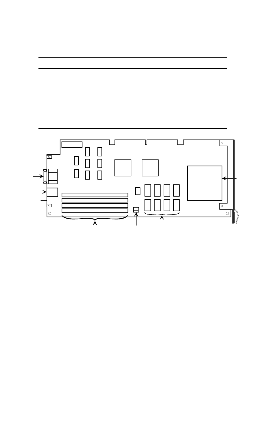
Expanding Your Server
i486 CPU Module Components/Connectors
Figure Legend Component
A CPU socket
B Secondary cache
C Server memory SIMM sockets
D Two serial port connectors
E Keyboard and mouse connectors
F Switch settings
D
E
0
1
2
3
C
J3
J4
J5
J6
F
B
A
DEC00607-2
Figure 3-5. i486 CPU Module Components/Connectors
3-12

Expanding Your Server
Pentium CPU Module Components/Connectors
Figure Legend Component
A Voltage regulator
B CPU socket
C Secondary cache socket
D Server memory SIMM sockets
E Serial port connectors
F Keyboard and mouse connectors
G Switch settings
D
0
1
E
F
2
3
4
5
J9
J8
J7
J6
J5
J4
G
C
A
B
DEC00602-2
Figure 3-6. Pentium CPU Module Components/Connectors
3-13

Expanding Your Server
Upgrading the CPU Module
Installing a higher-performance CPU module increases the capabilities of
your server. It also enables you to upgrade with future CPUs, install additional server memory, and install a larger capacity secondary cache module (Pentium CPU module only). To upgrade your CPU module:
1. Turn off your server. Disconnect any external devices and unplug
the power cord from the wall outlet. Unplug the power cord and
monitor cord from the back of the server.
2. Unlock and remove the left side panel.
3. Remove the screw that secures the CPU module to your server’s
rear panel.
4. Grasping both ends of the CPU module, carefully remove it from
the main logic board.
5. If you plan on installing additional server memory or a secondary
cache module on your existing CPU module, place it on an antistatic surface.
If not, store the CPU module in an anti-static package.
6. Install additional server memory. Refer to “Installing Additional
Server Memory” later in this chapter.
7. Install a secondary cache module (Pentium CPU module only).
Refer to “Installing a Secondary Cache Module” later in this chapter.
8. Prior to installing an upgraded or new CPU module, refer to Appendix A, “Technical Specifications,” to see if any configuration
switches need to be set.
3-14
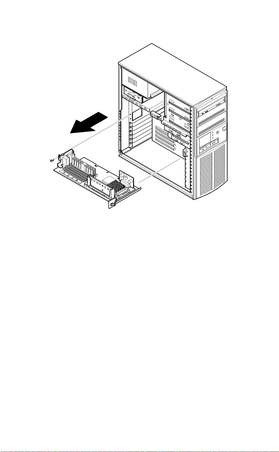
Expanding Your Server
DEC00591-3
Figure 3-7. Removing the CPU Module (Pentium CPU Module Shown)
3-15
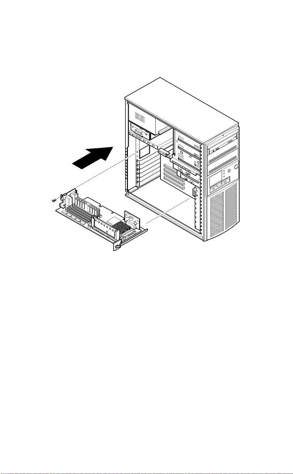
Expanding Your Server
9. Install the CPU module.
Make sure the metal bracket at the right-side of the CPU module is
firmly seated against the plastic fan housing.
DEC00591-4
Figure 3-8. Replacing the CPU Module (Pentium CPU Module Shown)
10. Replace the screw to secure the CPU module to your server’s rear
panel.
11. Replace and lock the left side panel.
3-16

Expanding Your Server
12. Reconnect the power cord and monitor cord to the back of the
server. Reconnect any external devices and plug the power cord
into the wall outlet.
13. Reboot and run the SCU.
From the main menu select Configure Computer and then
View and Edit Details.
Select Save and Exit to configure your server for the CPU mod-
ule.
Upgrading the CPU
Your CPU module is equipped with a ZIF socket (Socket 7 type) capable
of supporting higher performance Pentium processors. Contact your Digital sales representative for CPU availability and ordering information for
your computer.
To install a higher performance CPU:
1. Remove the CPU module.
2. Place the CPU module on an anti-static surface.
3-17

Expanding Your Server
3. Lift up on the release lever to release the CPU.
Remove the CPU, noting its pin 1 orientation (A, Figure 3-9).
A
DEC00606-2
Figure 3-9. Releasing the CPU (Pentium CPU Module Shown)
3-18
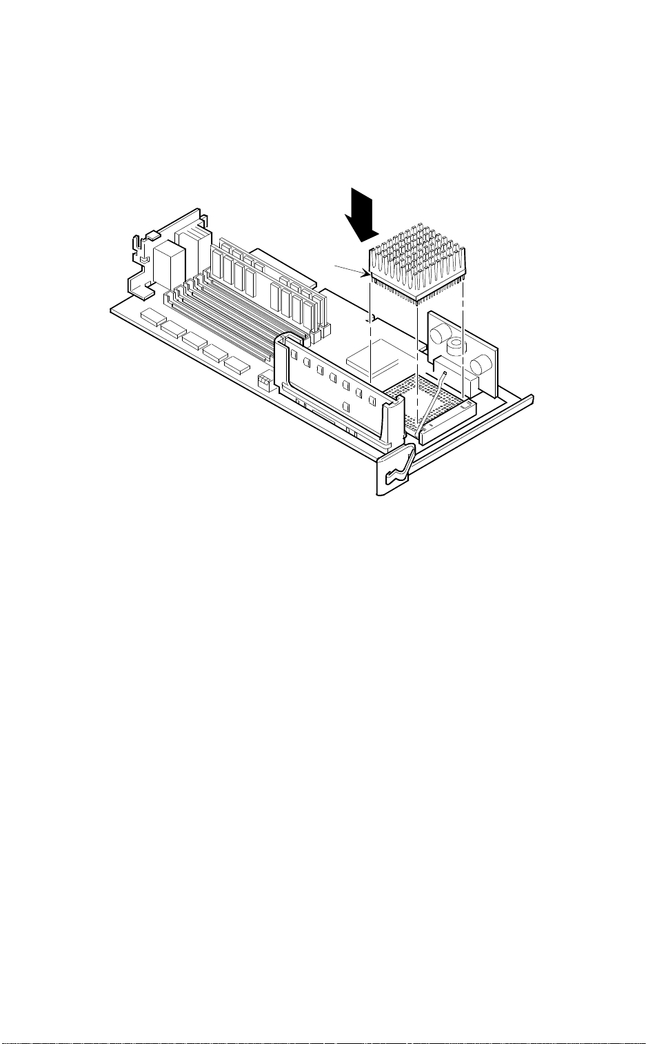
Expanding Your Server
4. Install the new CPU.
Make sure pin 1 on the CPU is aligned with pin 1 on the ZIF
socket. Pin 1 is located at the notched end of the CPU (A, Figure
3-10).
A
DEC00606-2
Figure 3-10. Installing a New CPU (Pentium CPU Module Shown)
5. Return the release lever to its original position.
6. Refer to Appendix A, “Technical Specifications,” to see if any configuration switches need to be set.
7. Install and secure the CPU module to the main logic board.
3-19

Expanding Your Server
Installing a Secondary Cache Module (Pentium CPU Module Only)
Your server’s Pentium CPU module comes with a 256 KB write-back standard or burst secondary cache module. Standard cache refers to asynchronous cache; “burst” cache refers to synchronous (higher performance)
cache. You can upgrade to a 512 KB secondary cache module by replacing the existing 256 KB cache module. To upgrade to a 512 KB cache,
perform the following:
1. Turn off your server. Disconnect any external devices and unplug
the power cord from the wall outlet. Unplug the power cord and
monitor cord from the back of the server.
2. Unlock and remove the left side panel.
3. Remove the CPU module and place it on an antistatic surface.
4. Holding the 256 KB secondary cache module only by the top edge,
carefully lift it away from the CPU module and place it in an antistatic package.
5. Holding the 512 KB secondary cache module only by the top
edge, carefully insert it into the socket on the CPU module. Make
sure it fully seats into the socket.
6. Install the CPU module making sure it is firmly seated into the
socket.
7. Replace and lock the left side panel.
8. Reconnect the power cord and monitor cord to the back of the
server. Reconnect any external devices and plug the power cord
into the wall outlet.
9. Reboot and run the SCU.
From the main menu select Configure Computer then select
View and Edit Details to enable the external cache option.
Select Save and Exit to configure your server for the secondary
cache.
3-20

Expanding Your Server
DEC00611
Figure 3-11. Installing a Secondary Cache Module
3-21

Expanding Your Server
Installing Additional Server Memory
Adding more memory allows your server to run larger, more complicated
software and run it quicker.
The amount of memory your server supports depends on the type of CPU
module you have installed. If you have the i486 CPU module installed,
your server will support up to 128 MB using 32 MB single in-line memory
modules (SIMMs) in SIMM sockets 0 through 3 (J3 through J6). If you
have the Pentium CPU module installed, your server will support up to 192
MB using 32 MB SIMMs in SIMM sockets 0 through 5 (J4 through J9).
Your server is shipped with at least 16 MB of memory. You can add 4 MB,
8 MB, 16 MB, or 32 MB SIMMs. When installing SIMMs:
• SIMMs must be installed in pairs. For example, a 32 MB SIMM in
socket 0 and a 32 MB SIMM in socket 1. You cannot mix SIMM
sizes within sockets.
• SIMMs must be the same type and speed.
• SIMMs must have an access time of 70 ns or less.
Refer to the section, “Installing a SIMM or Memory Module,” for detailed instructions on installing SIMMs.
Memory Configurations (i486 CPU Module)
SIMM 0 SIMM 1 SIMM 2 SIMM 3 Total
8 MB 8 MB 16 MB
8 MB 8 MB 4 MB 4 MB 24 MB
8 MB 8 MB 8 MB 8 MB 32 MB
16 MB 16 MB 32 MB
16 MB 16 MB 4 MB 4 MB 40 MB
16 MB 16 MB 8 MB 8 MB 48 MB
16 MB 16 MB 16 MB 16 MB 64 MB
32 MB 32 MB 64 MB
32 MB 32 MB 4 MB 4 MB 72 MB
32 MB 32 MB 8 MB 8 MB 80 MB
32 MB 32 MB 16 MB 16 MB 96 MB
32 MB 32 MB 32 MB 32 MB 128 MB
3-22

Expanding Your Server
0
1
2
3
J3
J4
J5
J6
Figure 3-12. SIMM Socket Locations (i486 CPU Module)
DEC00607-4
3-23

Expanding Your Server
Memory Configurations (Pentium CPU Module)
SIMM 0 SIMM 1 SIMM 2 SIMM 3 SIMM 4 SIMM 5 Total
8 MB 8 MB 16 MB
8 MB 8 MB 4 MB 4 MB 24 MB
8 MB 8 MB 4 MB 4 MB 4 MB 4 MB 32 MB
8 MB 8 MB 8 MB 8 MB 32 MB
16 MB 16 MB 32 MB
8 MB 8 MB 8 MB 8 MB 4 MB 4 MB 40 MB
16 MB 16 MB 4 MB 4 MB 40 MB
8 MB 8 MB 8 MB 8 MB 8 MB 8 MB 48 MB
8 MB 8 MB 16 MB 16 MB 48 MB
16 MB 16 MB 4 MB 4 MB 4 MB 4 MB 48 MB
16 MB 16 MB 8 MB 8 MB 4 MB 4 MB 56 MB
16 MB 16 MB 16 MB 16 MB 64 MB
32 MB 32 MB 64 MB
32 MB 32 MB 4 MB 4 MB 72 MB
16 MB 16 MB 16 MB 16 MB 4 MB 4 MB 72 MB
8 MB 8 MB 16 MB 16 MB 16 MB 16 MB 80 MB
8 MB 8 MB 32 MB 32 MB 80 MB
32 MB 32 MB 8 MB 8 MB 4 MB 4 MB 88 MB
32 MB 32 MB 8 MB 8 MB 8 MB 8 MB 96 MB
16 MB 16 MB 16 MB 16 MB 16 MB 16 MB 96 MB
32 MB 32 MB 16 MB 16 MB 96 MB
32 MB 32 MB 16 MB 16 MB 8 MB 8 MB 112 MB
32 MB 32 MB 32 MB 32 MB 128 MB
32 MB 32 MB 16 MB 16MB 16 MB 16 MB 128 MB
32 MB 32 MB 32 MB 32 MB 4 MB 4 MB 136 MB
32 MB 32 MB 32 MB 32 MB 8 MB 8 MB 144 MB
32 MB 32 MB 32 MB 32 MB 16 MB 16 MB 160 MB
32 MB 32 MB 32 MB 32 MB 32 MB 32 MB 192 MB
3-24

Expanding Your Server
0
1
2
3
4
5
0
1
2
3
4
5
J9
J8
J7
J6
J5
J4
J9
J8
J7
J6
J5
J4
Figure 3-13. SIMM Socket Locations (Pentium CPU Module)
DEC00602-4
3-25

Expanding Your Server
Installing a SIMM
To install a SIMM, perform the following:
1. Turn off your server. Disconnect any external devices and unplug
the power cord from the wall outlet. Unplug the power cord and
monitor cord from the back of the server.
2. Unlock and remove the left side panel.
3. Remove the CPU module and place it on an antistatic surface.
4. Install a SIMM into an appropriate socket on the CPU module at a
45 ° angle (A, Figure 3-14).
Be sure that the notch is oriented as shown. Rock the SIMM gently
until it is seated evenly into the bottom of the socket. Tip the SIMM
upright until the retaining clips at the ends of the socket both engage. (B and C, Figure 3-14).
CAUTION: Use care when installing SIMMs. The retain-
ing clips on the sockets can break if the SIMM is not seated
correctly in the socket.
5. Install the CPU module making sure it is firmly seated into the
socket.
6. Replace and lock the left side panel.
3-26

Expanding Your Server
-
A
A
B
B
C
DEC00089
Figure 3-14. Installing a SIMM
7. Reconnect the power cord and monitor cord to the back of the
server. Reconnect any external devices and plug the power cord
into the wall outlet.
8. Reboot and run the SCU.
From the SCU main menu, select Configure Computer then
select Save and Exit to configure your server for the additional
memory.
3-27

Expanding Your Server
Replacing the Server Battery
The server battery runs the server clock and retains any setup information
when it is turned off. If your server ever fails to retain the correct date,
time, or configuration settings when it turned on, you need to replace the
server’s battery.
To replace the battery, perform the following steps:
1. Record your server’s configuration settings using the SCU.
2. Turn off your server. Disconnect any external devices and unplug
the power cord from the wall outlet. Unplug the power cord and
monitor cord from the back of the server.
3. Unlock and remove the left side panel.
4. Remove the battery.
5. Install the new battery.
CAUTION: Make sure pin 1 on the battery is correctly
aligned with the pin 1 location on the socket (A, Figure 3-
15). The pin 1 location on the battery is designated by a
white dot in the lower left corner of the battery. Incorrect
installation may cause faulty server operation.
6. Replace and lock the left side panel.
7. Reconnect the power cord and monitor cord to the back of the
server. Reconnect any external devices and plug the power cord
into the wall outlet.
8. Reboot and run the SCU and configure your server using the recorded configuration settings from step 1.
3-28
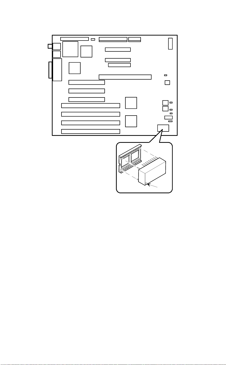
Expanding Your Server
Figure 3-15. Installing the Server Battery
A
DEC00592-3
3-29

Expanding Your Server
Installing Expansion Boards
Your Prioris LX server contains seven expansion board slots for installing
up to six EISA or PCI expansion boards. Four of the slots support extended industry-standard 32-bit EISA expansion boards. The remaining
three PCI local bus expansion slots support 32-bit PCI local bus expansion boards. This enables your server to deliver improved performance by
using a higher speed data path.
Expansion Slots
Expansion Slot
Description
Designation
EISA slots 2, 3, and 4 Supports extended industry-standard 32-bit
EISA expansion boards
EISA slot 1 Supports extended industry-standard 32-bit
EISA expansion boards
Designated as a shared slot with PCI slot 3
PCI slots 1 and 2 Supports bus mastering 32-bit PCI expansion
boards
PCI slot 3 Supports bus mastering 32-bit PCI expansion
boards
Designated as a shared slot with EISA slot 1
(1)
Only one expansion board can reside in EISA slot 1 or PCI slot 3 at any one time. These slots have
to share the expansion slot opening at the rear panel.
(1)
(1)
3-30

PCI SLOT 1
PCI SLOT 2
PCI SLOT 3
EISA SLOT 1
EISA SLOT 2
EISA SLOT 3
EISA SLOT 4
Expanding Your Server
DEC00592-4
Figure 3-16. Prioris LX Expansion Board Slots
3-31

Expanding Your Server
Use the following procedures to install any EISA, ISA or PCI local bus expansion board.
NOTE: Read and fully understand the documentation pro-
vided with the optional expansion board prior to installing it.
Also, you must run the SCU to configure your server before
installing any ISA expansion board.
1. Turn off your server. Disconnect any external devices and unplug
the power cord from the wall outlet. Unplug the power cord and
monitor cord from the back of the server.
2. Unlock and remove the left side panel.
3. Unscrew and remove the metal filler plate.
4. Insert the new expansion board into the socket in the main logic
board. Push the board firmly into the socket.
If necessary, use an appropriate card guide slot in the plastic fan
assembly at the front of the chassis.
5. Replace the screw to secure the expansion board.
6. Replace and lock the left side panel.
7. Reconnect the power cord and monitor cord to the back of the
server.
8. Reconnect any external devices and plug the power cord into the
wall outlet.
9. Run the SCU to configure any EISA or PCI expansion boards that
you installed.
3-32

Expanding Your Server
Figure 3-17. Installing an Expansion Board
DEC00171
3-33

Expanding Your Server
Installing Mass Storage Devices
Your server has three drive bay areas. Mass storage devices such as hard
disk drives, floppy diskette drives, CD-ROM drives and tape backup systems are installed in these drive bay areas. The three drive bay areas are:
• Upper drive bay area—This area has room for three 5¼-inch halfheight devices. Each drive bay is equipped with a removable panel
to accommodate devices requiring front panel access.
− The top drive bay contains a 5¼-inch SCSI CD-ROM drive
(standard on all Prioris LX servers).
− The bottom two bays of this area can be used to mount two
half-height devices or one full-height device. The drive rails
are removable to accommodate a full-height device.
• Lower drive bay area—This area has a drive bay assembly that
holds a 3½-inch diskette drive (standard on all Prioris LX servers)
and one hidden 3½-inch half-height device that needs no front
panel access. This hidden bay is typically used for mounting the
server's primary 1-inch high or 1.6-inch high hard disk drive.
• Rear drive bay area—This area has a drive bay assembly that
holds a 3½-inch half-height device. This hidden bay is typically
used for mounting an additional 1-inch high hard disk drive.
See Figure 3-2 to help you locate these bay areas on your Prioris LX server.
3-34

Expanding Your Server
SCSI Configuration Guidelines
Your Prioris LX Server includes an onboard Adaptec AIC-7850 SCSI-2
controller. The AIC-7850 controller connects directly to the PCI local bus
and supports up to seven industry-standard fast, narrow (8-bit), 50-pin
SCSI-2 devices. Your server has been supplied with a standard 50-pin
SCSI ribbon cable installed at the factory.
Additional SCSI devices can be added to your server by using an EISA- or
PCI-based SCSI controller installed in an available expansion slot in conjunction with an external SCSI expansion box.
Your server configuration, SCSI controller, and all SCSI devices must
work together for optimum performance. Use the following guidelines to
configure your server and all SCSI devices.
• The last physical SCSI devices on each end of the SCSI bus must
be terminated. If your SCSI device came with terminators installed,
you must remove or disable the terminator from the device before
you complete the installation.
• Your server is supplied with a fast, narrow (50-pin) connector cable
assembly. This cable terminates at CD-ROM drive leaving four
connectors for internal drives.
Refer to your SCSI device’s manufacturer documentation for the terminator location.
NOTE: This cable does not support wide (68-pin) SCSI
devices. A separate wide adapter must be added to the
server to support wide SCSI devices.
3-35

Expanding Your Server
• Each SCSI device (including the SCSI host adapter) must be configured with a unique ID number. SCSI host adapters usually default to ID 7. The SCSI CD-ROM drive defaults to ID 6. Use the
remaining IDs 0 through 5 to configure hard disk drives and other
SCSI devices. Hard disk drives should be configured to start with
SCSI ID 0 and the lower ID numbers.
• SCSI device drivers are required to operate your SCSI devices.
Your SCSI device drivers are located on the supplied CD-ROM
disk. You can copy these SCSI device drivers onto diskettes using
the ServerWORKS Quick Launch program on the CD-ROM disk.
• Use the SCSI
Select
configuration utility to check or change SCSI
device settings.
• If your server boots from a disk drive other than SCSI, make sure
all SCSI device drivers are installed on that disk drive. SCSI devices can be used with an IDE drive only if the IDE drive is configured as drive C.
3-36

Expanding Your Server
Expansion Brackets
You can install half-height devices in any of the three positions in the upper drive bay area. To install a 3½-inch device in the upper drive bay, you
must first install expansion brackets onto the device. Expansion brackets
will either be supplied with the device or can be purchased from Digital.
Contact your local Digital representative for additional information.
DEC00723
Figure 3-18. Installing Expansion Brackets on 3 1/2-inch Device
NOTE: The design of the expansion brackets might vary.
3-37

Expanding Your Server
Installing Devices in the Upper Drive Bay Area
To install a device in the upper drive bay area perform the following steps:
1. Turn off your server. Disconnect any external devices and unplug the
power cord from the wall outlet. Unplug the power cord and monitor
cord from the back of the server.
2. Unlock and remove both side panels.
3. Using a screwdriver from either side, remove the plastic filler panel by
gently prying it out from inside the server.
3-38

Expanding Your Server
DEC00594-2
Figure 3-19. Removing Plastic Filler Panel from the Second Drive Bay
3-39

Expanding Your Server
4. Insert the new device into the drive bay from the front.
5. If necessary, replace the plastic filler panel.
6. Connect the power and data cables to the device.
Refer to “Connecting Devices,” later in this chapter.
3-40
DEC00594-3
Figure 3-20. Inserting a Device into the Second Drive Bay

Expanding Your Server
Installing a Device in the Rear Drive Bay
NOTE: Only 3½-inch, one inch high devices can be in-
stalled into this drive bay area.
To install a device in the rear drive bay area perform the following steps:
1. Turn off your server. Disconnect any external devices and unplug the
power cord from the wall outlet. Unplug the power cord and monitor
cord from the back of the server.
2. Unlock and remove the left side panel.
3. While squeezing the two metal tabs together, remove the drive bay
assembly from the server (A, Figure 3-21).
3-41

Expanding Your Server
A
DEC00595-2
Figure 3-21. Removing the Rear Drive Bay Assembly
3-42

Expanding Your Server
4. Install a 3½-inch device onto the assembly.
DEC005 96
Figure 3-22. Attaching a 3½-Inch Device to the Rear Drive Bay Assembly
3-43
 Loading...