

Page 1
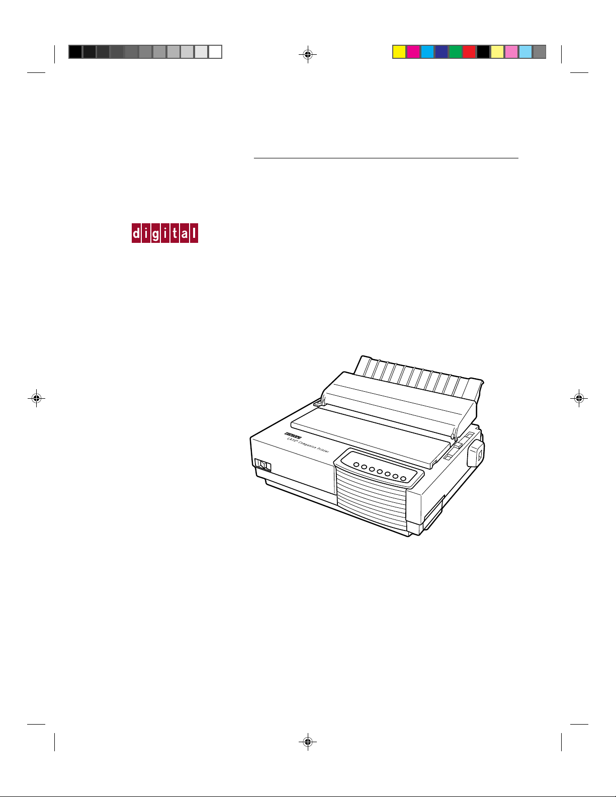
LA30
TM
User Guide
N
/LA30
W
Companion Printer
*1 Cover (1)-UG 28/05/96, 13:581
Order Number: EK-LA30E-UG-001
Page 2

*1 Cover (1)-UG 28/05/96, 13:582
Page 3
LA30N/LA30W Companion Printer
User Guide
Digital Equipment Corporation
Maynard, Massachusetts
#00_0 Title Page (2) 23/05/96, 14:091
Page 4

#00_0 Title Page (2) 23/05/96, 14:092
Page 5

Table of Contents
Preface .................................................................................................... vii
About This Guide............................................................................................................... vii
Printer Models and Options ............................................................................................... vii
Organization....................................................................................................................... viii
The LA30N and LA30W Model Specifications ....................................................... viii
Notes, Cautions and Warnings........................................................................................... ix
1. Introduction ........................................................................................ 1-1
Features .............................................................................................................................. 1-1
Options ............................................................................................................................... 1-2
2. Paper Handling ................................................................................... 2-1
Getting to Know the Printer’s Major Parts and the Control Panel ................................... 2-1
Parts of the Printer..................................................................................................... 2-2
Operations of the Control Panel................................................................................ 2-4
Selecting Paper .................................................................................................................. 2-7
Overview of Paper Operations .......................................................................................... 2-8
Adjusting for Paper Thickness .......................................................................................... 2-10
Using Single Sheets ........................................................................................................... 2-11
Loading a Single Sheet of Paper ............................................................................... 2-11
Ejecting Single Sheets............................................................................................... 2-13
Using Continuous Forms ................................................................................................... 2-14
Positioning the Paper Stack....................................................................................... 2-15
Loading Continuous Forms (Push Tractor and Rear Feed)...................................... 2-16
Loading Continuous Forms (Pull Tractor and Bottom Feed)................................... 2-19
Unloading Continuous Forms (Push-Feed Mode) .................................................... 2-24
Tearing Off Continuous Forms ................................................................................. 2-24
Feeding and Positioning Paper .......................................................................................... 2-26
Print Area Definition ................................................................................................. 2-26
Line Feed/Form Feed ................................................................................................ 2-28
T op-of-F orm Adjustment........................................................................................... 2-28
Switching Paper Types....................................................................................................... 2-29
Switching from Continuous Forms to Single Sheets (Push-Feed Mode)................. 2-30
Switching from Single Sheets to Continuous Forms (Push-Feed Mode)................. 2-30
Switching between Push-Feed and Pull-Feed........................................................... 2-31
Tips on Paper Handling ..................................................................................................... 2-32
General Tips .............................................................................................................. 2-32
Multipart Forms......................................................................................................... 2-32
Envelopes .................................................................................................................. 2-32
Labels ........................................................................................................................ 2-32
#00_2 TOC (2) 24/05/96, 10:573
iii
Page 6

3. Printing................................................................................................ 3-1
Selecting Print Features ..................................................................................................... 3-1
Using Commercial Software ..................................................................................... 3-2
Using the Control Panel ............................................................................................ 3-2
Selecting Macro 1 or Macro 2 .......................................................................... 3-3
Switching Macros and Selecting Features on the Control Panel ..................... 3-4
Selecting a Resident Font ................................................................................. 3-7
Changing the Protocol ...................................................................................... 3-8
Starting or Stopping Printing ............................................................................................. 3-9
Starting Printing ........................................................................................................ 3-9
Stopping and Viewing Printing ................................................................................. 3-9
Resuming Printing..................................................................................................... 3-9
Resuming from a Paper-Out...................................................................................... 3-9
Removing Printed Pages.................................................................................................... 3-10
Removing Single Sheets ........................................................................................... 3-10
Removing Continuous Forms ................................................................................... 3-10
4. Using Set-Up Mode ............................................................................ 4-1
What is Set-Up Mode for?................................................................................................. 4-1
How Set-Up Works ............................................................................................................ 4-2
Entering the Set-Up Mode ................................................................................................. 4-2
Overview of the Set-Up Mode........................................................................................... 4-5
Set-Up Mode Functions ............................................................................................ 4-5
Points to Remember .................................................................................................. 4-11
Printing the Printer Configuration ..................................................................................... 4-11
Deciding Which Options to Change.................................................................................. 4-13
Changing Macro 1 and Macro 2 Options .......................................................................... 4-14
Macro 1 and Macro 2 Options List.................................................................................... 4-15
Changing Install Options ................................................................................................... 4-25
Install Options List ............................................................................................................ 4-25
Adjusting Top-of-Form Origin .......................................................................................... 4-29
Changing Menu Access Options........................................................................................ 4-30
Exiting and Saving............................................................................................................. 4-30
Recalling Factory Settings................................................................................................. 4-31
Using the Diagnostic Functions......................................................................................... 4-31
Printing Test............................................................................................................... 4-31
Hex Dump Mode ....................................................................................................... 4-32
Set-Up Mode Quick Reference.......................................................................................... 4-34
iv
#00_2 TOC (2) 24/05/96, 10:574
Page 7

5. Maintenance........................................................................................ 5-1
Cleaning ............................................................................................................................. 5-1
Cleaning and Vacuuming the Printer ........................................................................ 5-1
Cleaning the Platen and Paper Bail Rollers .............................................................. 5-2
Cleaning the Print Head ............................................................................................ 5-3
Replacing the Ribbon Cartridge ........................................................................................ 5-3
Replacing the Print Head ................................................................................................... 5-5
6. Trouble-Shooting ................................................................................ 6-1
Solving Problems ............................................................................................................... 6-1
Print Quality Problems and Solutions....................................................................... 6-1
Paper Handling Problems and Solutions................................................................... 6-4
Operating Problems and Solutions............................................................................ 6-5
Printer Failures .......................................................................................................... 6-6
Diagnostic Functions ......................................................................................................... 6-6
Checking Vertical Alignment............................................................................................. 6-7
A. Supplies and Options........................................................................A-1
Supplies.............................................................................................................................. A-1
Options ............................................................................................................................... A-1
Documentation................................................................................................................... A-1
Installing Options............................................................................................................... A-2
Installing the Color Kit.............................................................................................. A-2
B. Printer and Paper Specifications .....................................................B-1
Physical Specifications ...................................................................................................... B-1
Functional Specifications................................................................................................... B-2
Performance Specifications ............................................................................................... B-4
Paper Specifications........................................................................................................... B-5
Print Area................................................................................................................... B-5
Paper Thickness......................................................................................................... B-7
C. Command Sets...................................................................................C-1
DEC PPL2 Quick Reference Guide................................................................................... C-2
IBM Proprinter X24E and XL24E Quick Reference Guide ............................................. C-22
Epson ESC/P2 Quick Reference Guide............................................................................. C-26
D. Interface Information ......................................................................... D-1
Parallel Interface ................................................................................................................ D-1
Serial Interface ................................................................................................................... D-4
Serial Options ............................................................................................................ D-5
Cable Wiring.............................................................................................................. D-5
Buffer Control ........................................................................................................... D-5
#00_2 TOC (2) 24/05/96, 10:575
v
Page 8

E. Character Sets.................................................................................... E-1
DEC PPL2 Protocol ........................................................................................................... E-1
Common to IBM Proprinter X24E and XL24E Protocol and Epson ESC/P2 Protocol ... E-18
Default Sets ............................................................................................................... E-18
IBM Proprinter X24E and XL24E Protocol...................................................................... E-24
IBM Set 1/2 ............................................................................................................... E-24
Epson ESC/P2 Protocol ..................................................................................................... E-25
National Character Sets............................................................................................. E-25
F. Resident Fonts................................................................................. F-1
Glossary............................................................................................... GL-1
Index..................................................................................................... IN-1
vi
#00_2 TOC (2) 24/05/96, 10:576
Page 9

About this Guide
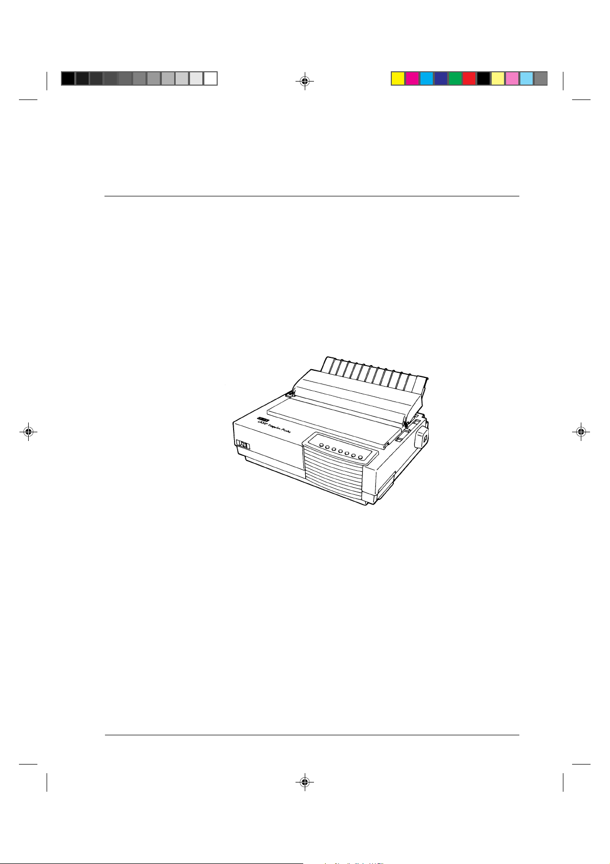
Thank you for buying a Digital LA30 Companion Printer. You can expect years of reliable
service with very little maintenance. The information provided in this guide applies both to
the Digital LA30N Companion Printer (80-column printer) and to the Digital LA30W
Companion printer (136-column printer). However, illustrations are of LA30N Companion
Printer. This guide explains how you can use your printer to full advantage. It is written for
both new and experienced printer users.
This guide consists of two parts: Setting Up Your Printer and User Guide. The former
describes how to install and set up your printer. This part is easily identifiable, as each page
has a gray border. The latter, this part, describes how to use your printer and printer options,
how to keep the printer in good working condition, and what to do should something go
wrong. Detailed procedures are provided for first-time users. Experienced users can skip
some of the details, using the table of contents and chapter introductions to locate specific
information.
This part has several appendixes, a glossary, and an index. Appendix A lists supplies and
options available from your dealer or authorized representative of Digital Equipment
Corporation.
Preface
Printer Models and Options
Model LA30N is an 80-column printer and model LA30W is a 136-column printer. Both
models have a dual interface made up of Bitronics parallel and DEC-423 serial. The power
supply of the printer is either for 100-120 VAC input or for 220-240 VAC input. You must
specify the print line and the power rating when purchasing the printer. Other options
include a color print feature which you can add by yourself after purchasing the printer. The
configuration is:
LA30N/LA30W
Basic specifications
Print line at 10 cpi*: 80 columns for LA30N
Interfaces: Bitronics parallel and DEC-423 serial
Alternative specification
Power supply: 100–120 VAC or 220–240 VAC
User add-on options
Color Kit
* cpi: characters per inch
#00_3 Preface 23/05/96, 13:557
136 columns for LA30W
vii
Page 10
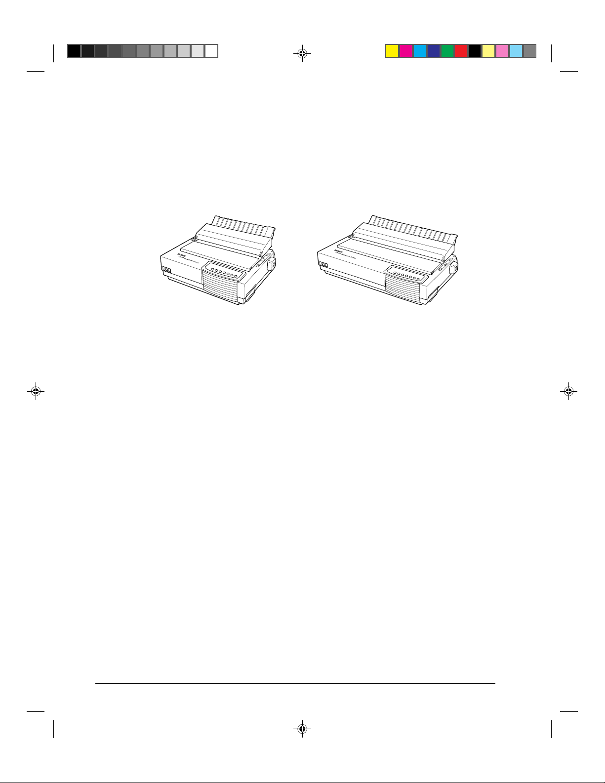
The LA30N and LA30W Model Specifications
The main difference between the LA30N and the LA30W is the “print span”.
The LA30N is an 80-column printer and the LA30W a 136-column printer. As shown in the
following figure, the physical specifications are thus different (size, weight, ...).
Digital LA30N Companion Printer Digital LA30W Companion Printer
Some minor differences concern mechanical internal parts that do not impact the general
uses of the printer (top cover hinges, bail rollers mechanism, ...). The only visible difference
concerns the accurate location of the notch scale of the paper thickness lever.
Specification differences are clearly identified further in this User Guide.
Organization
The user guide is organized as follows:
1 - Introduction
This chapter introduces the printer and identifies key features and options that enhance the
printer’s capabilities.
2 - Paper Handling
This chapter explains how to load your printer and use paper with it.
3 - Printing
This chapter covers basic printing operations and provides detailed descriptions of everyday
operations from the printer’s control panel, including print feature selection.
viii
#00_3 Preface 23/05/96, 13:558
Page 11
4 - Using Set-Up Mode
This chapter describes how to change the printer’s optional settings, such as print features,
hardware options, and top-of-form. Most settings only affect print features such as the type
style and page format. Note that certain settings directly affect hardware and software
compatibility. Refer to this chapter as indicated in the part Setting Up Your Printer or as
required.
5 - Maintenance
This chapter explains basic maintenance procedures for this printer.
6 - Trouble-Shooting
This chapter describes problem-solving techniques. Before you contact your dealer for help,
check the list of problems and solutions provided in this chapter.
At the end of this guide, you will find several appendices, a glossary, and an index.
Appendix A gives order numbers for printer supplies and options, explaining how to install
them. Other appendices provide additional technical information about the printer.
Notes, Cautions and Warnings
The text contains three different types of annotation which should always be read.
Note: This NOTE annotation provides you with additional information, or indicates
where you can find it.
Caution: This CAUTION annotation should catch your attention, advising you of a
particular situation/problem which may occur/be avoided as a result of a certain
sequence of operations. It may also contain a reminder to execute a particular
operation.
Warning: This WARNING annotation indicates a specific procedure which must be strictly
observed. Failure to comply with the instructions given may result in injury to the
operator and/or damage to the printer.
#00_3 Preface 23/05/96, 13:559
ix
Page 12

#00_3 Preface 23/05/96, 13:5510
Page 13
Introduction
1
Introduction
Congratulations on purchasing a Digital LA30 Companion Printer. This printer is a
compact, versatile printer that offers maximum compatibility with today’s software packages
and personal computers. The 24-wire print head provides crisp, clear printing for business,
office, and home environments. This printer is also easy to install and use.
Features
Key printer features and options are listed in the next two sections.
• Software compatibility. This printer, which operates with the DEC PPL2 protocol, the
IBM Proprinter X24E (LA30N) or IBM Proprinter XL24E (LA30W) protocol and the
Epson ESC/P2 protocol (for Epson LQ870 or LQ1170 printers or equivalent).
• Various character sets. For the DEC PPL2 protocol, 31 character sets (twenty-five 94-
character sets and six 96-character sets) are available. For IBM Proprinter X24E and
XL24E protocol, set 1, set 2, and 30 default sets (code pages and specific character sets)
are available. For Epson ESC/P2 protocol, 15 national character sets and 30 default sets
(code pages and specific character sets) are available.
#01 Chapter 1 23/05/96, 14:121
Digital LA30 Companion Printer
1-1
Page 14

Introduction
• Multiple fonts. The printer has eighteen resident fonts: Ten bit-map fonts — Draft,
High-speed (HS) Draft, High-impact (Hi) Draft, Courier 10, Pica 10, Prestige Elite 12,
Compressed 17, Boldface PS, OCR A, and OCR B; six outline fonts — Timeless and
Nimbus Sans, each in upright, italic, and bold; three outline fonts — Courier in upright,
italic, and bold (available for the Epson ESC/P2 protocol only); and nine Barcode fonts
— Code 3 of 9, Industrial 2 of 5, Interleaved 2 of 5, Matrix 2 of 5, EAN 8, EAN 13,
UPC-A, Codabar, and Postnet.
• High-speed printing. At 10 cpi, print speed ranges from 100 cps for letter quality to
333 cps for high-speed draft quality.
• 64K bytes of input buffer. 64K bytes are available for storing input data and
downloading custom fonts. A minimum download buffer capacity is available separately.
• Simple switching of paper types. The ability to “park” continuous forms makes it easy
to switch between continuous forms and single sheets.
• Bottom feeding capability. The tractor unit is removable and can be converted to push-
feed or pull-feed. Installing the tractor unit on the platen allows the paper to be fed
through the slot at the bottom of the printer.
• Automatic tear-off advancing. With factory settings of the Set-Up mode, continuous
forms’ perforations are automatically advanced up to the tear bar at the end of each job
so that forms can be torn off. The tear-off feed can be also activated by pressing the
Pause button.
• Auto viewing. Paper (continuous forms or single sheets) is automatically advanced at
the end of each printing so that the last printed line can be read.
• Maintenance-free. The printer only requires periodic cleaning and changing of the
ribbon cartridge.
• Windows printer driver. Printer drivers for Windows 3.x and Windows 95 are
delivered with your printer. The printer driver is a control program to be installed on
your computer for controlling document printing on your printer (for example,
controlling the page size, the paper orientation, and so on). It receives print data from
your application software, converts the data into commands that the printer can execute,
and sends the commands to the printer.
Options
Printer add-on options are listed below. For details, see Appendix A “Supplies and
Options”.
• Color kit. You can turn your monochrome printer into a color printer. Seven-color
printing using a color ribbon is possible if supported by your software.
1-2
#01 Chapter 1 23/05/96, 14:122
Page 15

Paper Handling
This chapter explains how your printer uses paper. Topics covered are:
• Getting to know the printer’s major parts and the control panel
• Selecting paper
• Overview of paper operations
• Adjusting for paper thickness
• Using single sheets
• Using continuous forms (push-tractor feed and pull-tractor feed)
• Feeding and positioning paper
• Switching paper types
Paper Handling
2
Tips for paper handling are given at the end of this chapter. Check that section if you are
using multipart forms, envelopes, or labels.
Getting to Know the Printer’s Major Parts and the Control Panel
This section describes the major parts and controls of the printer and operations of the
control panel. Take a moment to become familiar with the printer.
#02 Chapter 2 23/05/96, 14:151
2-1
Page 16
Paper Handling
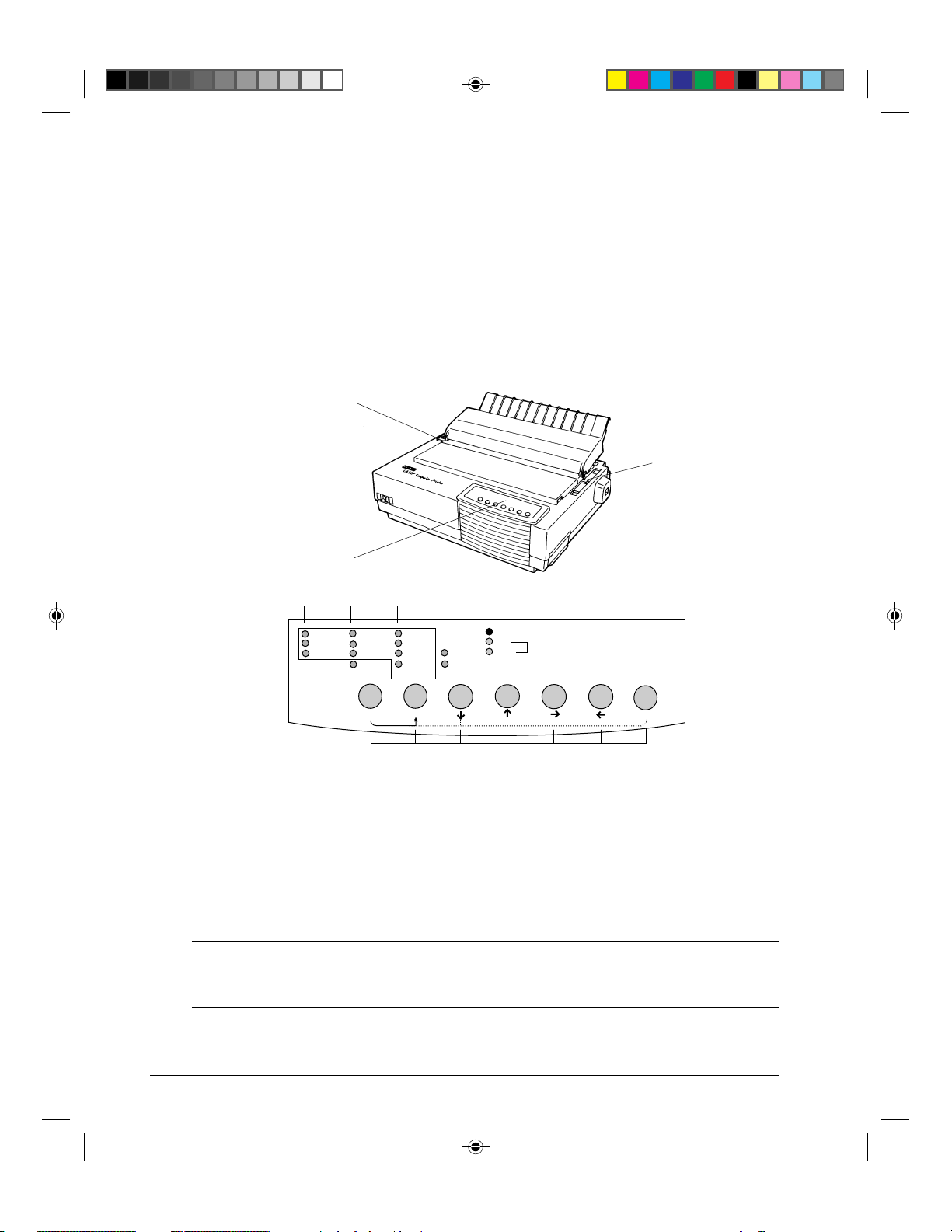
Parts of the Printer
i
!8
o
u
!0
!1
q
w
e
r
t
y
!2
!7
2-2
#02 Chapter 2 23/05/96, 14:162
!6
!3
!4
!5
Front and Rear Views
Page 17

Paper Handling
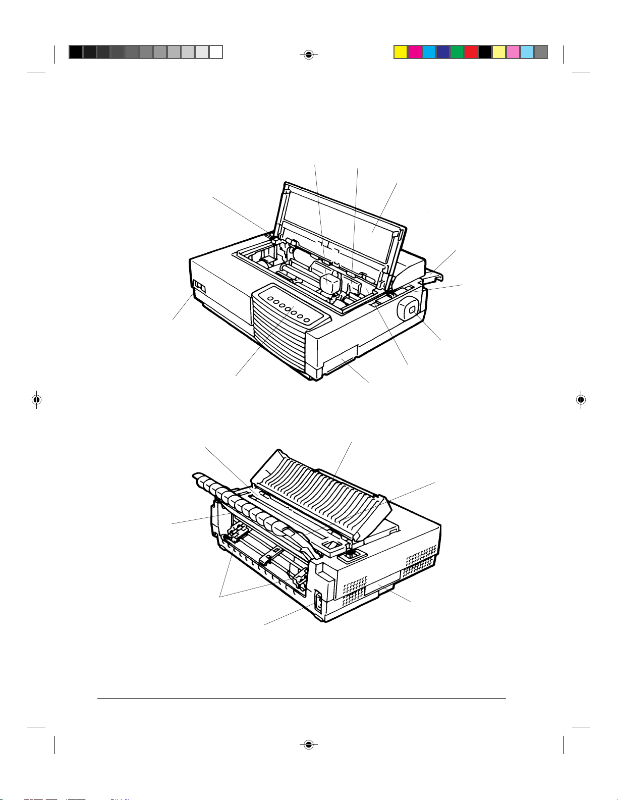
The figures on the previous page show front and rear views of the printer. The following
parts are indicated:
Front View
1. Front cover (to protect the print head)
2. Cut sheet stand (to hold printing and printed pages)
3. Paper thickness lever (to adjust the print head gap)
4. Platen knob (to manually advance the paper)
5. Platen (to support the paper)
6. Interface connector (to connect the printer to the host system)
7. Control panel (to load and feed paper, select print features, or change the
printer’s optional settings)
8. Power switch (to switch the printer on/off)
9. Paper select lever (to switch the paper source)
10. Print head (to apply ink to the page)
11. Print guide (to indicate the print line)
Rear View
12. Acoustic cover (to reduce sound noise)
13. Paper guide (to insert single sheets and envelopes)
14. Rating label (to indicate the printer power specifications)
15. Power connector (to connect the printer to the power supply)
16. Forms tractors (to hold and feed continuous forms)
17. Back cover (to protect forms tractors)
18. Top cover (to protect the platen and serve as the tear bar)
#02 Chapter 2 23/05/96, 14:163
2-3
Page 18
Paper Handling
Operations of the Control Panel
This section summarizes status indications and operations of the control panel in Normal
mode. For details on Set-Up mode, see Chapter 4 “Using Set-Up Mode”.
Normal mode operation includes everyday operations, such as paper handling, font
selection, macro selection, and protocol selection. The first table lists basic states
represented by the Ready and Fault indicators. The second table lists Normal mode
operations and required user response. Operations are listed by functions.
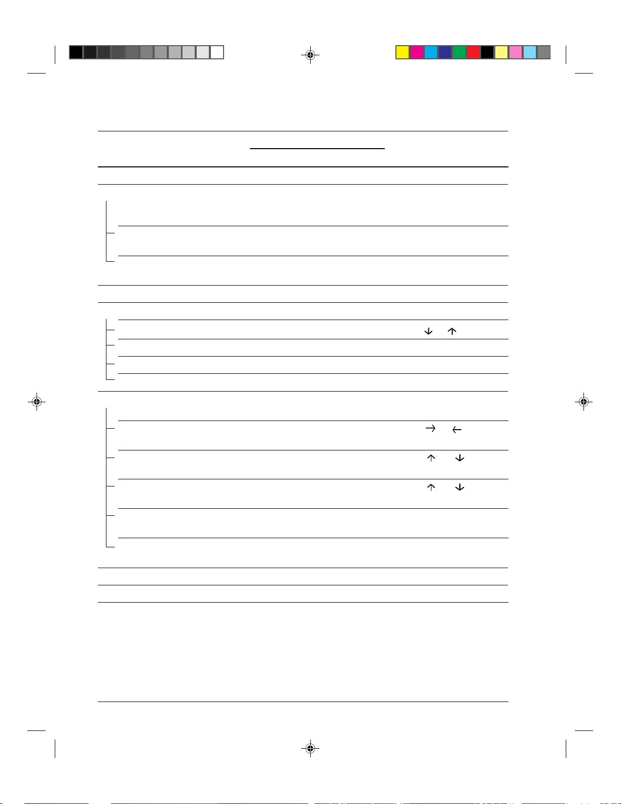
Basic States of the Printer
Indicator Status Printer Status
Ready
On The printer is ready for printing
or
The printer is receiving or printing data.
Blinking The printer is not ready and holds printing data.
Off The printer is not ready and it does not hold printing data.
Fault On The printer is out of paper.
Blinking slowly The printer has software errors (paper jam, interface
error, carriage error, paper unloading error, etc.).
Blinking fast The printer detected diagnostic errors at power-up.
2-4
#02 Chapter 2 23/05/96, 14:164
Page 19
Paper Handling
Control Panel Operations
— : This operation has no connection with this condition.
N/A : The condition does not apply because this operation is executed before powering on.
*1
Operation Required Conditions
Ready Printing
Load continuous forms paper — Not printing On Press FF/Load.
Load single sheet paper — Not printing On Press FF/Load if single sheet
Feed paper a page — Not printing Off Press FF/Load.
Feed paper a line — Not printing Off Press LF.
*2
Required Action
Fault
load is switched from AUTO
to MANUAL in Set-Up mode.
Advance perforation to tear bar — Not printing Off
Press
Pause
if the TEAR
option is switched from AUTO
to MANUAL in Set-Up mode,
or
press FF/Load.
Advance paper for viewing — Not printing Off
Press
Pause
if the TEAR
option is switched from AUTO
to MANUAL in Set-Up mode.
Return paper to previous position — Not printing Off
Press
Pause
if the TEAR
option is switched from AUTO
to MANUAL in Set-Up mode,
or
press FF/Load.
Eject single-sheet paper — Not printing Off Press FF/Load or Park or turn
the printer off and on again.
Unload continuous-forms — Not printing Off Press Park.
*3
paper
Pause printing On Printing Off Press Pause.
Resume printing Blinking Not printing Off Press Pause.
Resume printing after a fault Off Not printing On Clear error and press Pause.
Resume printing after paper-out Off Not printing On Load paper.
Place printer in Ready state Off Not printing Off Press Pause.
Place printer in pause state On — Off Press Pause.
Enter Normal mode N/A N/A N/A Turn power on without
Printing test N/A N/A N/A Turn power on while pressing
#02 Chapter 2 23/05/96, 14:165
pressing any buttons
FF/Load.
2-5
Page 20
Paper Handling
*1
Operation Required Conditions
Ready Printing
*2
Fault
Required Action
Select a resident font — Not printing Off Press Font.
Enter Macro selection mode — Not printing Off Press Macro. (M1 and M2
will turn blinking
alternately for 3 seconds.)
Select Macro 1 —
*4
Off Press M1 within 3 seconds
after pressing Macro.
Select Macro 2 —
*4
Off Press M2 within 3 seconds
after pressing Macro.
Switch the protocol — Not printing *4Off Press Protocol.
Enter Top-of-Form Adjustment mode
— Not printing Off
Press
Set-Up/Quit
and
Top
Move paper by 1/60 inch Off — Off Press or button.
Use the adjustment temporarily Off — Off Press Set-Up/Quit.
Use the adjustment permanently
Off — Off Press Exit/Save.
Clear the adjustment Off — Off Press Top.
Enter Set-Up mode N/A N/A N/A Turn power on while
pressing Set-Up/Quit.
Move cursor to select Off Not printing Off Press or button.
a Set-Up Function or Value
Move cursor to select Off Not printing Off Press or button.
a Set-Up Option
Select a Set-Up Function Off Not printing Off Press or button.
or Value
Select a Set-Up Value and Off Not printing Off Press Exit/Save.
move cursor to SAVE&EXIT
Quit Set-Up mode without
Off Not printing Off Press Set-Up/Quit.
saving values
Clear software-detected errors — — Blinking Press Pause.
Initialize the printer — — —
Turn power off and on again.
.
*1 In Normal mode operation, all buttons except Pause are inactive in the Busy state in which the printer is receiving
or printing data.
*2 Not printing includes the following situations: the printer is ready and awaiting data, or the Pause button is
pressed and the printer is awaiting data, or the Pause button is pressed during printing.
*3 This operation is available in the rear-feeding push-tractor mode.
*4 Switching is not done if the printer is holding printing data.
2-6
#02 Chapter 2 23/05/96, 14:166
Page 21

Printer Acoustical Feed-Backs
Except for paper handling and when the factory setting for beep is not changed, the printer
beeps in the following ways when you press a control panel button, as follows.
• A short beep indicates that the printer accepts your pressing or specification.
• A longer beep indicates that your specification is invalid.
• In a certain mode, a middle long beep indicates that the specified mode becomes active
and a short beep indicates the end of the mode.
• When the Fault indicator lights, the printer also makes a longer beep.
Selecting Paper
The printer can handle either single sheets or continuous forms. Single sheets, also called
cut sheets, include envelopes and noncontinuous, multipart forms. Continuous forms
include labels and multipart forms fed into the printer using the forms tractors.
For best results, use paper that meets the specifications listed in the following table. (See
Appendix B “Printer and Paper Specifications” for detailed specifications.) If you are
unsure of the suitability of a particular type of paper, try testing the paper or consult your
dealer.
Paper Handling
Paper Specifications
Paper Size
LA30N LA30W
Continuous Width 102 to 267 mm (4 to 10.5 in) 102 to 420 mm (4 to 16.5 in)
forms Length 102 mm (4 in) or greater 102 mm (4 in) or greater
Cut sheets Width 102 to 267 mm (4 to 10.5 in) 102 to 420 mm (4 to 16.5 in)
Length 76 to 364 mm (3 to 14.3 in) 76 to 420 mm (3 to 16.5 in)
Paper Thickness and Number of Copies
Description
Thickness 0.35 mm (0.014 in) maximum total thickness.
Copies 1 to 5 copies, including the original.
For carbon-interleaved paper, the carbon counts as a copy.
#02 Chapter 2 23/05/96, 14:167
2-7
Page 22
Paper Handling
Overview of Paper Operations
The following levers and buttons are used in paper handling:
• Paper select lever q at the top left corner of the printer
• Paper thickness lever w at the top right corner of the printer
• All buttons y on the control panel e (Primary and alternative functions are labelled
respectively above and under each button.)
The following figure shows the location of each lever, indicators, and buttons:
q
w
e
Draft
HSDraft
HiDraft
r
Courier 10 Bold PS
Prestige 12
Comp. 17
Ready
Pause
Set-Up/Quit Top
Time PS
Nimb. PS
Soft Ctrl.
Font
t
Fault
DEC
EP2
PPX24
M1
M2
Protocol Park LF FF/Load
Macro
M1
M2
Exit/Save
y
Paper select lever q Font indicators r
Paper thickness lever w Macro indicators t
Control panel e Buttons y
Printer Levers and Buttons
The following table summarizes the use of levers and buttons in paper handling. More
detailed information is provided later in this chapter.
Caution: To load or feed paper, the printer must be:
• In the Ready state but not receiving or printing data
• In the Pause state
2-8
#02 Chapter 2 23/05/96, 14:168
Page 23
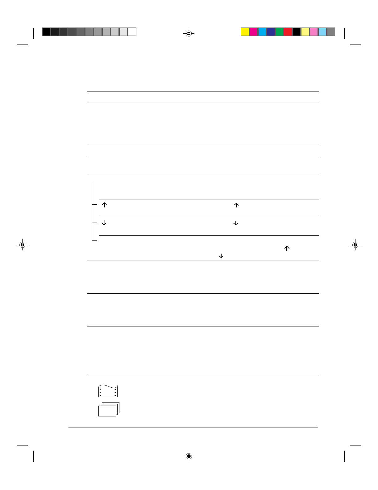
Levers and Buttons Used for Paper Handling
Lever/Button Purpose Action
Paper Handling
FF/Load
Form feed Press FF/Load to execute a form feed.
Continuous forms are fed forward by one
page. Single sheets are ejected.
Load paper Press FF/Load to feed paper to the top of
form position.
LF Line feed Press LF to feed paper forward by one line.
Park Unload forms Press Park to retract continuous forms to
the “park position.”
Set-Up/Quit + Top Press Set-Up/Quit and Top at the same time
Press the button to feed paper forward
Exit/Save Save TOF value Press Exit/Save to permanently store the
Enter Top-of-Form
(TOF) Adjustment
mode
Increase TOF value by
1/60 inch
Decrease TOF value by
1/60 inch
to enter TOF Adjustment mode where the
paper loading position can be adjusted.
by 1/60 inch in TOF Adjustment mode.
Press the button to feed paper backward
by 1/60 inch in TOF Adjustment mode.
TOF position adjusted by the button and
the button in TOF Adjustment mode.
Pause Press Pause to advance the forms
Advance forms to the
tear bar when forms
are at Top-of-Form
(TOF) position
perforation to the tear bar. Tear off the
forms, then press Pause again to return the
forms to the previous position.
Paper select lever * Select paper path Move the paper select lever forward for
Paper thickness lever Select the number corresponding to the
* The following graphics are engraved on the casing.
#02 Chapter 2 23/05/96, 14:169
Adjust for paper
thickness or number of
copies
Continuous forms
Single sheets
single sheets.
Move the paper select lever backward for
continuous forms.
number of copies (including the original).
Vary the setting upward or downward
(including A to D) to optimize printing.
Select D when replacing ribbon or clearing
a paper jam.
2-9
Page 24

Paper Handling
Adjusting for Paper Thickness
The printer can handle paper with different thicknesses, including multipart forms with up to
five parts (original plus four copies). For details on paper thickness specifications, see
Appendix B “Printer and Paper Specifications.”
The paper thickness lever, located at the top right corner of the printer, allows you to adjust
for different paper thicknesses. Be sure to adjust the paper thickness lever whenever you
change the number of copies being printed.
The paper thickness lever q has nine settings: 1 to 5 and A to D. Use the following table
to determine the appropriate setting for your paper; then, move the paper thickness lever to
the appropriate position.
2-10
#02 Chapter 2 23/05/96, 14:1610
q
Adjusting the Paper Thickness Lever
Page 25
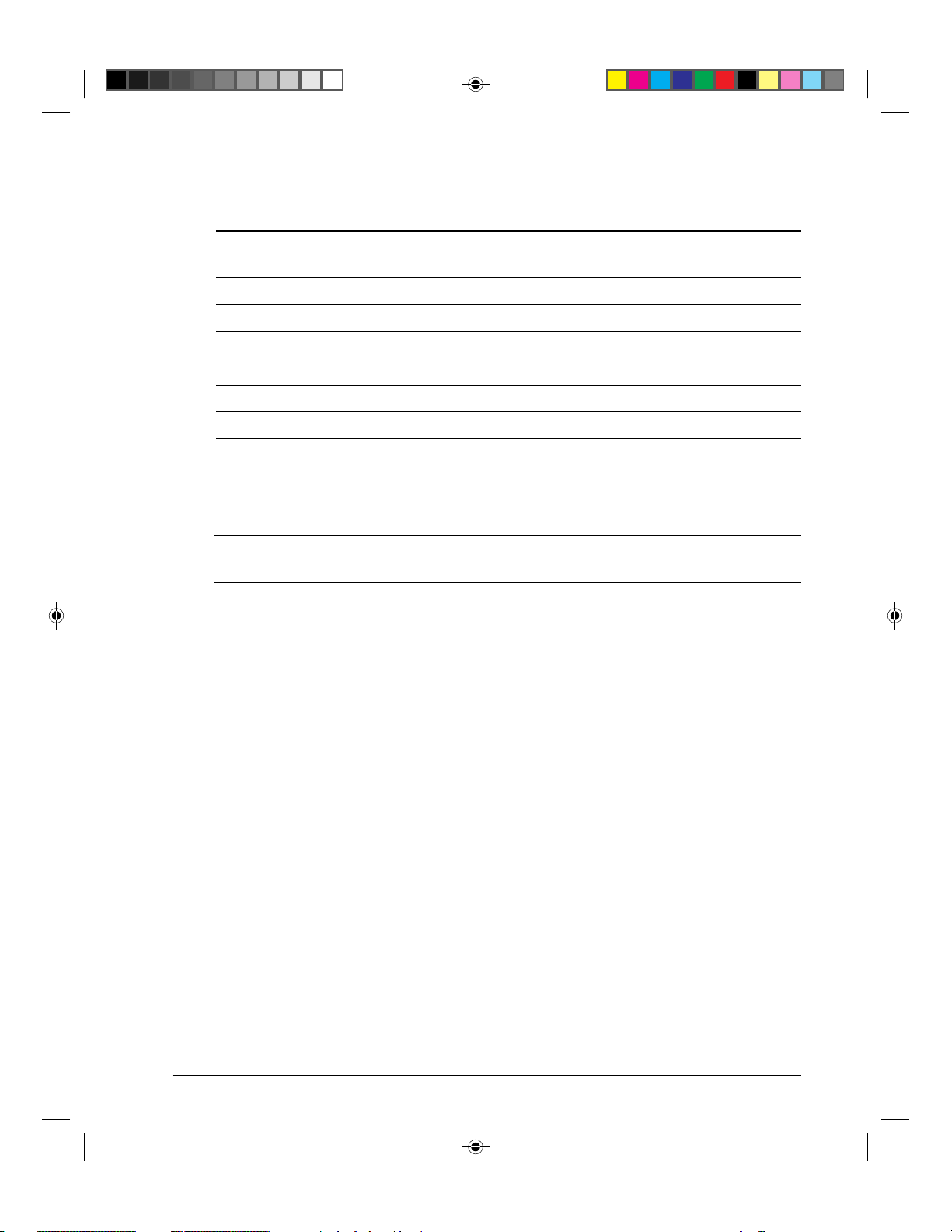
Paper Thickness Lever Positions
Paper Handling
Number of Copies Position
(Including the Original)
*1
*2
1 copy 1
2 copies 2
3 copies 3
4 copies 4
5 copies 5
Ribbon replacement D
*1 For carbon-interleaved paper, the carbon counts as one copy.
*2 Vary the position upward or downward (including A to D) to optimize printing. Select D when replacing a
ribbon or clearing a paper jam. For labels and envelopes, use the trial-and-error approach to determine a
satisfactory position.
Caution: If printing is messy, the ribbon misfeeds, or the paper jams, move the lever one
position higher.
Using Single Sheets
This section describes how to load paper in the cut sheet stand. The cut sheet stand allows
paper to be loaded manually, one sheet at a time.
Loading a Single Sheet of Paper
To load a sheet of paper into the cut sheet stand:
1. Make sure that the printer is turned on. Check that rear-fed continuous forms are
retracted to the park position. (For details, see the section “Unloading Continuous
Forms” later in this chapter.)
2. If necessary, reset the paper thickness lever. (See the section “Adjusting for Paper
Thickness” earlier in this chapter.)
3. Move the paper select lever forward. (This lever is at the top left part of the printer.)
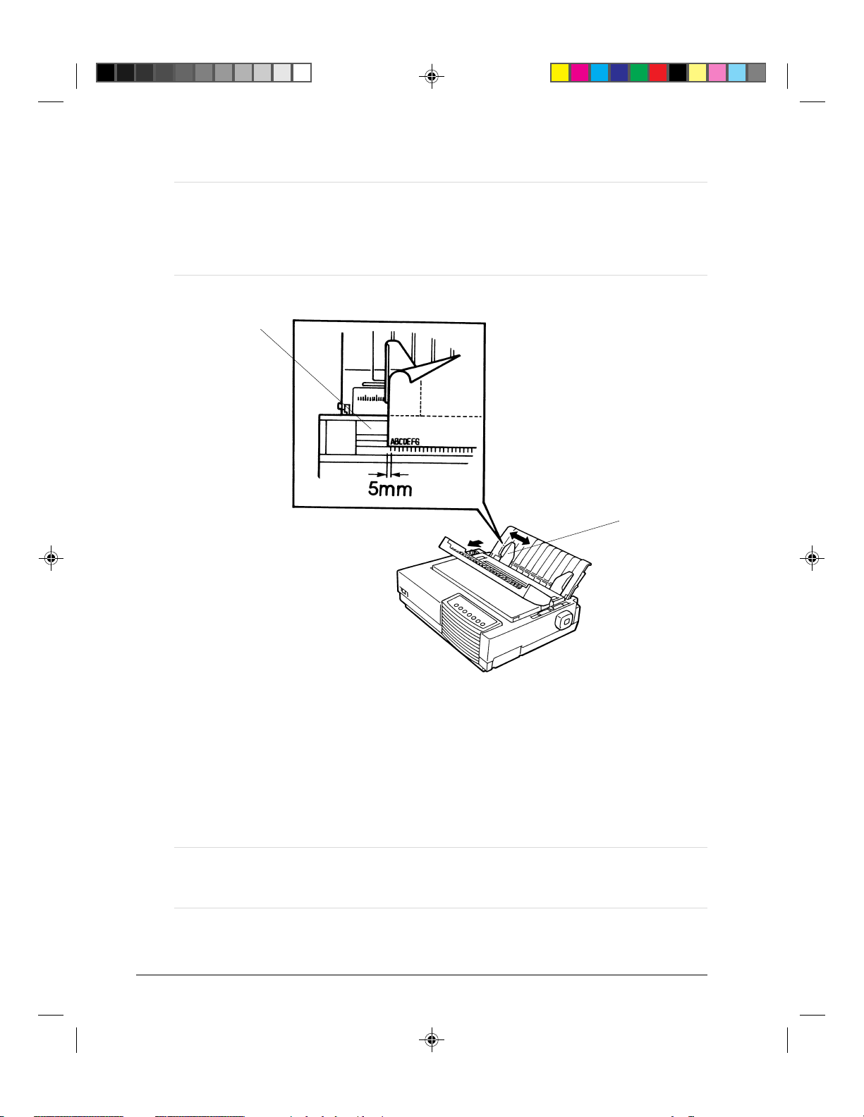
4. Raise the cut sheet stand. Position the left paper guide in accordance with the Note
below. Note that the movable range of the paper guide is limited.
#02 Chapter 2 23/05/96, 14:1611
2-11
Page 26
Paper Handling
Note: Below the left paper guide q, the cut sheet stand has a scale graduated in units
of 0.1 inch. When the left paper guide is positioned all the way to the right, the
left margin is 5 mm (0.2 inch). To help align paper, also use the inch-based ruler
on the top cover w of the printer. The gradations on the ruler are for 10
columns per inch.
w
q
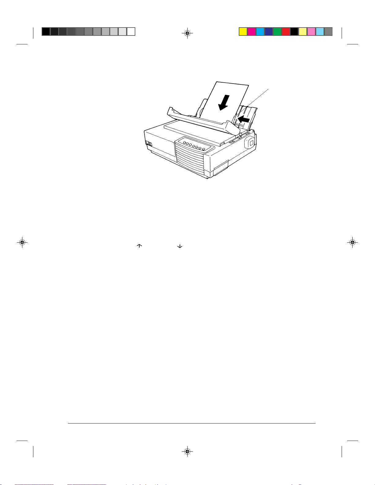
5. Adjust the right paper guide e to the width of paper. Insert the paper into the cut sheet
stand. Make sure that the bottom edge of the paper engages snugly with the platen. The
paper will automatically advance to the top-of-form position if the Single Sheet Load
option of the Set-Up mode is set to Automatic.
Note: The factory setting for the Single Sheet Load option is automatic loading, two
seconds after paper detection. If you set this option to manual, you will have to
press FF/Load to feed the paper.
2-12
#02 Chapter 2 23/05/96, 14:1612
Setting Paper Select Lever and Left Paper Guide
Page 27
Paper Handling
e
Loading a Sheet of Paper
6. If you want to slightly adjust the Top-of-Form position, the first line on which printing
can start, adjust the Top-of-Form position of the paper using control panel buttons. Press
the Set-Up/Quit and the Top buttons at the same time. The M1 and M2 indicators flash
alternately with the DEC and PPX24 indicators, indicating Top-of-Form Adjustment
mode. Press the button or the button. The paper will move forward or backward
in 1/60-inch increments. Press the Set-Up/Quit button after adjusting the position. Note
that this adjustment is temporarily saved. It will not be active at next power-up of the
printer. For permanent adjustment, see the section “Feeding and Positioning Paper” later
in this chapter.
7. Place the printer in the Ready state. Print a sample page and check the page margins.
Make the following adjustments, as necessary:
• Horizontal alignment. Readjust the paper guides if required.
• Top-of-form setting. Use the printer Set-Up mode (see Chapter 4 “Using Set-Up
Mode”) or the TOF Adjustment mode (see the section “Feeding and Positioning
Paper” later in this chapter).
• Margin settings. Use your software or the printer Set-Up mode (see Chapter 4
“Using Set-Up Mode”).
Ejecting Single Sheets
If you print using software, each sheet is ejected automatically upon the completion of the
page printing. To manually eject sheets of paper:
• Press the FF/Load button to execute a forward form feed.
• Turn the platen knob.
#02 Chapter 2 23/05/96, 14:1613
2-13
Page 28
Paper Handling
Using Continuous Forms
Continuous forms paper, fanfolded at the horizontal perforations, is ideal for printing rough
drafts and long files. The paper is fed into the printer using the forms tractor unit. The
forms tractor unit, which is removable, can be used in two different ways. If the forms
tractor unit is mounted at the rear of the printer, it pushes paper from the rear to the platen.
This is called push-tractor feeding. If the forms tractor unit is mounted at the top of the
printer, it pulls paper from the bottom or rear of the printer to the platen. This is called pulltractor feeding.
Caution: When using continuous forms with the cut sheet stand in up position, always
spread the cut sheet stand paper guides to their extreme position before feeding
the paper. This will prevent the paper from jamming against the acoustic cover.
2-14
#02 Chapter 2 23/05/96, 14:1614
Page 29
Paper Handling
Positioning the Paper Stack
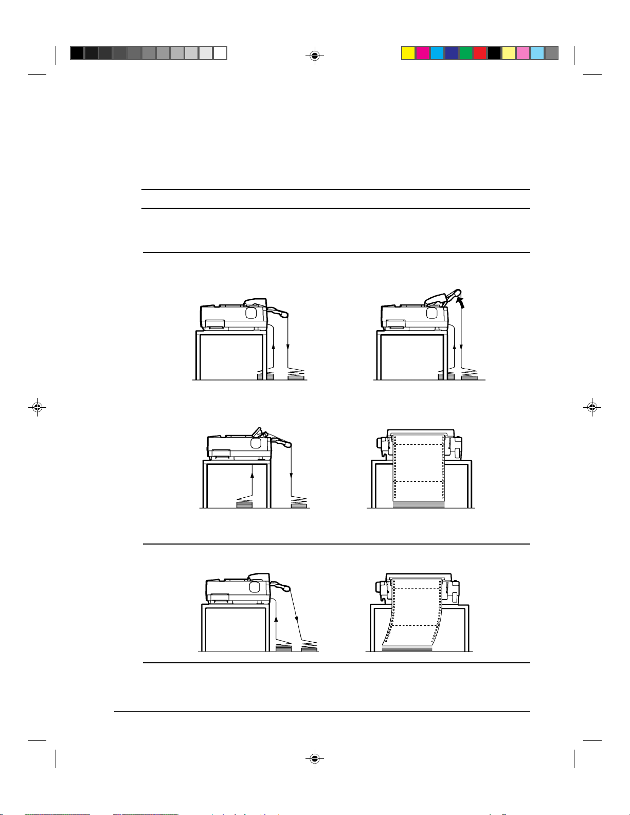
Place the stack of continuous forms paper directly below the rear of the printer q for push,
rear feed or below the bottom slot of the printer w for pull, bottom feed.
Caution:
When using paper-stapled multipart forms in push feed, raise the cut sheet stand e.
After the paper is installed in the printer, the paper path should look like this:
Good placement
q
Push-feed, from rear slot Push-feed, from rear slot
with paper-stapled multipart forms
w
e
Pull-feed, from bottom slot
Bad placement
#02 Chapter 2 23/05/96, 14:1615
Placement of Continuous Forms
2-15
Page 30
Paper Handling
Loading Continuous Forms (Push Tractor and Rear Feed)
This section explains how to use continuous forms when the tractor unit is installed at the
rear of the printer. The tractor unit pushes continuous forms. This condition applies when
you first use the printer.
To load continuous forms paper:
1. Make sure that the printer is turned on. Remove any single-sheet paper from the printer.
2. If necessary, readjust the paper thickness lever for continuous forms. (See the section
“Adjusting for Paper Thickness” earlier in this chapter.)
3. Move the paper select lever q to the rear of the printer.
e
r
w
q
Preparing to Load Continuous Forms Paper
4. To access the forms tractors w, lock the cut sheet stand e and the back cover r
together and raise them in the up position.
2-16
#02 Chapter 2 23/05/96, 14:1616
Page 31

Paper Handling
5. For both forms tractors w, release the tractor locking levers t by pulling them up.
Open the tractor paper holders y.
y
u
t
12 mm
Positioning the Tractor Using the Tractor Guide
6. Position the right forms tractor (as seen from the rear of the printer) in accordance with
the Note below. Push the right locking lever down to secure the tractor. Center the
middle forms support.
Note: The tractor guide u can be found below the right forms tractor, as seen from the
back. This tractor guide is a short inch-based ruler graduated in 10 columns per
inch. Use this ruler to help position the tractor. When the paper edge is
positioned to the leftmost line, the left margin is 12 mm (0.5 inch) including the
perforation area.
7. Once the right forms tractor is positioned, lock it by pushing down its locking lever.
#02 Chapter 2 23/05/96, 14:1717
2-17
Page 32

Paper Handling
8. Fit the paper feed holes onto the left and right tractor pins. Adjust the left forms tractor
(as seen from the rear of the printer) to accommodate the width of the form. Close the
paper holders y.
y
Adjusting Paper Tension
9. Pull the left tractor (as seen from the rear) to extend the paper flat. Do not stretch the
paper taut. Push the left locking lever down to secure the tractor in place. Unlock the
back cover from the cut sheet stand to close it.
10.When using paper-stapled multipart forms, leave the cut sheet stand e raised in the up
position. For other continuous forms paper, lower the cut sheet stand to the down
position.
e
Lowering the Cut Sheet Stand
11.Press the FF/Load button to advance the paper to the top-of-form position from which
printing can start. The printer is automatically placed in the Ready state.
2-18
#02 Chapter 2 23/05/96, 14:1718
Page 33

Paper Handling
12.Print a sample page and check the page margins. Make the following adjustments, as
necessary:
– Horizontal alignment. Move the forms tractors as required.
– Top-of-form setting. Use the printer Set-Up mode (see Chapter 4 “Using Set-Up
Mode”) or the Top-of-Form Adjustment mode (see the section “Feeding and
Positioning Paper” later in this chapter).
– Margin settings. Use your software or the printer Set-Up mode (see Chapter 4
“Using Set-Up Mode”).
Loading Continuous Forms (Pull Tractor and Bottom Feed)
Caution: When manipulating the tractor unit, always be careful not to pull on plastic
parts (below the forms tractors) in order to avoid printing problems (such as
printing on the platen at the end of the paper in push-feed).
Better manipulate the metallic parts of the tractor unit.
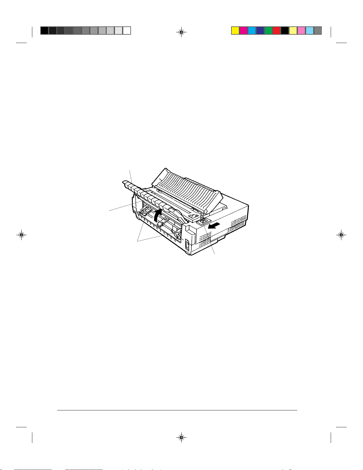
This subsection explains how to use continuous forms when the forms tractor unit is
installed at the top of the printer. The forms tractor unit pulls continuous forms. This is
called pull-tractor feed. To use pull-tractor feed, you must remove the forms tractor unit
from the rear of the printer and install it on the top of the printer.
For pull-tractor feed, this printer is equipped with a paper path slot at the bottom of the
printer to allow for continuous forms feed from under the printer. You must use a desk or
rack that has an appropriate paper path slot. For the appropriate paper path, see the section
“Positioning the Paper Stack” earlier in this section.
Warning: Turn the printer off before reinstalling the forms tractor unit.
To reinstall the forms tractor unit for pull-tractor feed:
1. Set the cut sheet stand and the back cover together to the up position to access the forms
tractor unit.
#02 Chapter 2 23/05/96, 14:1719
2-19
Page 34

Paper Handling
2. Pull up both ends of the tractor unit to detach the catches q of the tractor unit from the
support studs w. Then pull the tractor unit.
q
w
3. Set the cut sheet stand and the back cover to the down position.
2-20
#02 Chapter 2 23/05/96, 14:1720
Removing the Tractor Unit
Page 35

Paper Handling
4. Open the acoustic cover and the top cover e to access the top of the printer.
5. Position the catches q of the tractor unit on the support studs r near the platen shaft.
A. Push the forms tractor unit toward the front of the printer.
B. Snap down the tractor unit into place so that the catches click on the rear studs.
B
K
q
A
K
r
e
6. Turn the platen knob to make sure that the tractor gear fully engages the platen shaft
gear. Lean the top cover and the acoustic cover against the tractor unit.
The following are the procedures to take when you want to feed continuous forms paper
from under the printer (bottom feed).
To load continuous forms paper:
1. Make sure that the bottom slot of the printer is adjusted with the slot of the desk or
printer rack.
2. Set the paper thickness lever to position D (widest gap).
3. Move the paper select lever to the rear (continuous forms).
#02 Chapter 2 23/05/96, 14:1721
Installing the Tractor Unit for Pull-tractor Feed
2-21
Page 36

Paper Handling
4. Open the front cover q, with taking care of not totally removing it.
5. Place the continuous forms paper below the table and pass the paper through the slot of
the table then through the bottom slot of the printer up to the platen.
q
Passing Continuous Forms Paper From Under the Printer
6. Close the front cover q and open the top cover.
7. Open the two holders of the left and right tractors. (Each tractor has a larger main holder
w and a smaller subholder e.)
w
e
Opening the Two Holders
8. Set the continuous forms on the tractors and position the tractors to stretch the forms taut
in the same way as described for push-tractor feed.
2-22
#02 Chapter 2 23/05/96, 14:1822
Page 37

Paper Handling
9. Turn the platen knob r to adjust the print start position and turn the printer on. The
horizontal embossed rib under the red cursor on the print head carriage corresponds to
the base line of the characters to be printed.
r
Setting Continuous Forms Paper on the Tractors
10.Lean the top cover against the tractor unit.
11.Adjust the paper thickness lever to the appropriate position.
12.Press the Pause button to place the printer in the Ready state. Print a sample page and
check the first line and the page margins. Make the following adjustments, as necessary:
– Horizontal alignment. Move the forms tractors as required.
– Margin settings. Use your software or the printer Set-Up mode (see Chapter 4
“Using Set-Up Mode”).
Caution: In the pull-feed mode, reverse feeding is allowed up to 1/3 inch and the print
accuracy is lower than the accuracy available with the push-feed mode. Use the
pull-feed mode when printing labels and so on that are affected by curling.
#02 Chapter 2 23/05/96, 14:1823
2-23
Page 38

Paper Handling
Unloading Continuous Forms (Push-Feed Mode)
To unload continuous forms:
1. Make sure that the paper select lever is set to the rear position.
2. Press the Park button. The continuous forms paper is retracted to the park position. If
the paper cannot be retracted in one operation, continue to press the Park button until the
paper is parked.
Note: The printer can retract continuous forms paper a maximum of 50.8 cm (20
inches) per operation.
3. To remove the paper, raise the tractor paper holders and lift out the paper.
Note: To unload continuous forms fed by the pull-tractor, set the paper thickness lever
to D, then remove the paper manually.
Recovering from an Unexpected Unloading Operation
If you have accidentally pressed the Park button, you can cancel this operation in two ways,
only if this unexpected operation was unsuccessful (paper not actually parked and Fault
indicator blinking).
• Press the Pause button.
The printer switches to the Ready state and the paper moves according to the setting of
the TEAR Set-Up option.
• Press the FF/Load button.
The paper moves back to the place it was positioned before you pressed the Park button.
Tearing Off Continuous Forms
Caution: Continuous forms paper that is fed by the pull-tractor cannot be torn off in the
following way.
Automatic-Tear-Off Advancing
Your printer has a special “tear bar” that allows you to tear off printed pages without wasting
paper. The tear bar is located on the top cover.
Your printer is factory-set for automatic tear-off. When a printing job ends (including a
form feed command), the bottom perforation of the last printed page is automatically
positioned in front of the tear bar. You can change the positioning delay from one to five
seconds, using the Set-Up mode. The printer is placed in the Pause state (Ready indicator
off).
2-24
#02 Chapter 2 23/05/96, 14:1824
Page 39

Paper Handling
Note: If the printing job does not include a form feed command, the paper is only
automatically fed so that you can see the last printed line. Press on the FF/Load
button to position the next paper perforation in front of the tear bar.
The paper is automatically retracted when the printer receives the next data. For tearing off
the paper, see the next subsection “Manual Tear-Off Advancing”.
Manual T ear-Off Advancing
If you have set the TEAR option of the INSTALL function to MANUAL, tear off the paper in
the following way when a printing job ends (including a form feed command).
1. Press the Pause button to position the paper perforation in front of the tear bar.
Note: If the printing job does not include a form feed command, after pressing the
Pause button the paper is only automatically fed so that you can see the last
printed line. Press on the FF/Load button to position the next paper perforation
in front of the tear bar.
Caution: If the paper perforation is not positioned in front of the tear bar, the length of
your paper may not be specified correctly in your software or the Set-Up mode.
Check that the paper length is specified correctly. For information on specifying
page length using the Set-Up mode, see Chapter 4 “Using Set-Up Mode”.
2. Tear the paper off at the perforation.
Tearing Off Continuous Forms
3. Press the Pause button again to retract the forms back to the top-of-form position.
2-25
#02 Chapter 2 23/05/96, 14:1825
Page 40

Paper Handling
Feeding and Positioning Paper
Print Area Definition
• TOF (Top-of-Form):
This value defines the distance between the edge of the paper and the place where you
allow the printing to begin (position of line number 1). You can adjust this distance
according to the condition of your paper (for example, pre-printed forms). When you
load the paper, the printer feeds the paper to this position, waiting for printing
commands.
• L (Form Length):
Set the corresponding Set-Up option (FORM LENGH) according to the actual physical
page length (distance between two perforations for continuous forms). This will allow
the printer to know exactly where the print head is and to position it at the same position
when a form feed occurs.
• Top line q:
This is the line where the printing actually starts. To define a top margin, select the
number of this line within Set-Up mode (TOP MRGN option). Example: In the
following picture, TOP MRGN option is set to 3.
• Bottom line w:
This is the line where the printing actually stops. To define a bottom margin, select the
number of this line within Set-Up mode (BOTTOM MRG option). Example: In the
following picture, BOTTOM MRG option is set to 50.
• Left column e:
This is the column where the printing actually starts. To define a left margin, select the
number of this column within Set-Up mode (LEFT MARGN option). Example: In the
following picture, LEFT MARGN option is set to 4.
• Print area r:
Print area defined by the corresponding Set-Up options: Form Length, Top-of-Form,
Top Margin, and Bottom Margin.
• Paper perforation t:
The perforation defines the physical page length.
2-26
#02 Chapter 2 23/05/96, 14:1826
Page 41

Paper Handling
e
r
1
2
3
4
5
6
7
8
... ...
48
49
50
51
52
12345
ABCDEFGHIJ ···
ABCDEFGHIJ ···
ABCDEFGHIJ ···
...
6
TOF
q
L
w
t
TOF
1
2
3
4
5
6
...
Print Area Definition
2-27
#02 Chapter 2 23/05/96, 14:1827
Page 42

Paper Handling
Line Feed/Form Feed
Use the line feed/form feed function to move paper forward. This function is valid
whenever the printer is not receiving or printing data and has no fault. Pressing the LF
button advances the paper one line. Pressing the FF/Load button feeds one sheet of paper.
Except using the Park button for unloading paper or using the Top-of-Form Adjustment
mode for fine-adjusting the Top-of-Form position, you are not allowed to execute “reverse”
feed from the control panel. To feed paper backward, manually rotate the platen knob.
Remember that the Top-of-Form will slip from the original setting.
T op-of-Form Adjustment
Note: To know the Top-of-Form definition, see the previous section “Print Area
Definition”.
The Top-of-Form adjustment is available for single sheets or continuous forms fed by the
push-tractor. The adjustment is reflected to the Top-of-Form setting of Macro 1 or Macro 2
currently selected from the control panel.
Note: This adjustment is not available for continuous forms fed by the pull-tractor.
You can adjust the Top-of-Form value within the range from 0 to 99/60 inches.
Note: The horizontal embossed rib under the red cursor on the print head carriage
corresponds to the base line of the characters to be printed.
1. Position the paper at the current Top-of-Form position:
– For continuous forms, park the paper, then press the FF/Load button.
– For a single sheet, simply insert the sheet in the cut sheet stand.
Paper is automatically fed to the Top-of-Form position, if the Set-Up option
S-SHEET LD (Single Sheet Load) is set to AUTO. Otherwise, press the FF/Load
button.
2. Enter the Top-of-Form mode by pressing the Set-Up/Quit and Top buttons at the same
time. The printer beeps and the M1 and M2 indicators flash alternately with the DEC and
PPX24 indicators, indicating the Top-of-Form mode.
2-28
#02 Chapter 2 23/05/96, 14:1828
Page 43

Paper Handling
3. Adjust the Top-of-Form value:
– To increase the Top-of-Form value of a 1/60 inch, press the button.
The paper moves forward.
– To decrease the Top-of-Form value of a 1/60 inch, press the button.
The paper moves backward.
– To reset the Top-of-Form value to 0, press the Top button.
The paper moves to the edge of the page (position 0).
Note: If you reach the limit of the permitted range, the printer beeps and the paper
stops moving.
4. Save the Top-of-Form value:
– To permanently save the value, press the Exit/Save button.
The printer returns to Normal mode.
– To temporarily save the value, press the Set-Up/Quit button.
The printer returns to Normal mode. (The new value is lost at next power-off.)
Note: The use of the and buttons for micro-feeding is available for some cases of
software errors (Fault indicator blinking).
Switching Paper Types
If you have more than one type of job, it is often necessary to switch between continuous
forms and single sheets. This section explains how to switch between paper types. It is not
necessary to remove the continuous forms paper from the printer.
Caution: This function is not available for continuous forms paper that is fed by the pull-
tractor.
#02 Chapter 2 23/05/96, 14:1829
2-29
Page 44

Paper Handling
Switching from Continuous Forms to Single Sheets (Push-Feed Mode)
To switch from continuous forms to single sheets:
1. Tear off your printed pages.
2. Retract the forms paper to the park position by pressing the Park button. The Fault
indicator turns on.
Caution: Retracting many pages by using the Park button without tearing off will cause
paper jams. To avoid damage to your printed pages, be sure to tear off the
printed pages before retracting the continuous forms paper.
3. Move the paper select lever forward to the single sheet position.
4. Raise the cut sheet stand to the up position. (For details, see the section “Using Single
Sheets” earlier in this chapter.) Put a sheet of paper on the cut sheet stand with its
bottom edge aligned with the platen. The paper automatically advance to the top-ofform position if the option S-SHEET LD (Single Sheet Load) is set to AUTO.
Otherwise, press the FF/Load button to advance the single sheet paper to the top-of-form
position .
You are now ready to print using single sheets.
Switching from Single Sheets to Continuous Forms (Push-Feed Mode)
To switch from single sheets to continuous forms:
1. If a sheet of paper is loaded, remove the paper by turning the platen knob or pressing the
FF/Load button.
2. Move the paper select lever to the rear to the continuous forms position.
3. Press the FF/Load button. The continuous forms paper advances from the park position
to the top-of-form position.
You are now ready to print using continuous forms paper.
2-30
#02 Chapter 2 23/05/96, 14:1830
Page 45

Paper Handling
Switching between Push-Feed and Pull-Feed
Caution: When manipulating the tractor unit, always be careful not to pull on plastic
parts (below the forms tractors) in order to avoid printing problems (such as
printing on the platen at the end of the paper in push-feed).
Better manipulate the metallic parts of the tractor unit.
To allow the printer to properly detect the switching operation, follow the next procedure:
1. Unload the paper.
2. Turn the printer off.
3. Install the tractor unit for the other feed mode.
4. Turn the printer on.
5. Load the paper.
To Reinstall the Tractor Unit for Push-Tractor Feed:
1. Open the acoustic cover and the top cover.
2. Pull up both ends of the tractor unit to detach the catches of the tractor unit from the
support studs. Then pull the tractor unit.
3. Set the cut sheet stand and the back cover to the up position.
4. Keep the tractor unit horizontally (see the horizontal plane in the figure) so that the top
catches q of the tractor unit are in front of the inner support studs w of the printer.
5. Push the tractor unit toward the front of the printer until the top catches snap into the
inner studs. Then snap down the tractor unit into place.
q
Installing the Tractor Unit for Push-tractor Feed
w
6. Close the top cover and the acoustic cover.
#02 Chapter 2 23/05/96, 14:1831
2-31
Page 46

Paper Handling
Tips on Paper Handling
General Tips
• Use high-quality paper. Do not use paper that is wrinkled or curled at the edges.
• Do not use paper with staples or metal parts.
• Do not use paper with unpredictable variations in thickness, such as paper with partial
multilayers, paper with embossed printing, and labels with the backing sheet exposed.
• Store paper in a clean, dry environment.
Multipart Forms
• Avoid using carbon-interleaved single sheets if possible. Printing tends to become
misaligned on the bottom sheet.
• Set the paper thickness lever to best accommodate the multipart form thickness.
• To ensure smoother feeding of paper-stapled, multipart forms, raise the cut sheet stand to
support the forms.
Envelopes
When printing envelopes, use the cut sheet stand. Note the following:
• Set the paper thickness lever to best accommodate the envelope thickness.
• When loading envelopes, make sure that the envelope flaps face forward. Otherwise, the
envelopes may jam in the printer.
Labels
• Be careful to check operating conditions when using labels. Labels are sensitive to
temperature and humidity.
• Only use labels mounted on continuous forms backing sheets. Do not print labels
mounted on single sheet backing. Labels mounted on single sheet backing tend to slip
and printing becomes crooked.
• Do not leave labels loaded in the printer. If labels curl around the platen, jamming may
occur when printing is resumed.
• Set the paper thickness lever to best accommodate the label thickness.
• Test-print labels before running a job. If jams occur, set the paper thickness lever to a
wider position. If jamming problems continue, try a different type of label.
• We recommend you to use the pull-tractor feed mode for printing labels. If using the
push-tractor feed mode:
– Use the NO TEAR value of the TEAR option in the Set-Up mode.
– Do not unload labels using the Park button. Jamming may occur during backward
feeding.
– Do not use the printer tear-off feature when printing labels. If the labels are retracted,
the backing may peel off and the labels may jam in the printer.
2-32
#02 Chapter 2 23/05/96, 14:1832
Page 47

Printing
3
Printing
This chapter describes the following everyday printing operations:
• Selecting print features
• Starting, stopping, or resuming printing and viewing last printed lines
• Removing printed pages
The Font button, the Macro, M1, and M2 buttons, the Protocol button, and the Pause button
are used for these operations which are described in detail in this section. For a summary of
the operation of these buttons, see the section “Getting to Know the Printer’s Major Parts
and the Control Panel” in Chapter 2 “Paper Handling”.
Instructions for loading and handling paper are also given in Chapter 2 “Paper Handling”.
Selecting Print Features
The print features you select determine how your printer interprets commands from the
computer and how your printed pages will look. For example, print features include the
following:
• Protocol
• Font
• Pitch (characters per horizontal inch)
• Line spacing (lines per vertical inch)
• Page length and margins
To select print features, you can use either commercial software or the printer control panel.
The method you use depends on the capabilities of your software. If your software has most
of the features you require, you may rarely – if ever – have to use the control panel. In fact,
your software often overrides the printer settings.
If your software has limited values, you can use the printer control panel to select print
features. Sometimes, the control panel enables you to select features not available through
your software. For example, you can change the top-of-form position or select a character
set for printing your document.
#03 Chapter 3 23/05/96, 14:281
3-1
Page 48

Printing
Using Commercial Software
Many commercial software packages offer a wide variety of print features, including some
features that are not supported by this printer. For example, software often provides a wider
range of font sizes than the printer can accommodate. Software also allows you to specify
multiple fonts on a single page and multicolor printing. To determine which features your
software supports and how to select them, refer to your software documentation.
Using the Control Panel
This printer can directly select some print features from the control panel. These features,
listed on the control panel, are two predetermined sets (macros) of print features, nine
resident fonts, and three protocols. Use the Macro, Font, and Protocol buttons as follows:
• Macro to select one of the two sets of print features, Macro 1 (M1) and Macro 2 (M2)
• Font to select one of nine resident fonts (You can access three other f onts in Set-Up
mode)
• Protocol to select one of the three protocols
Draft
HSDraft
HiDraft
Courier 10 Bold PS
Prestige 12
Comp. 17
Ready
Pause
Set-up/Quit Top
Time PS
Nimb. PS
Soft Ctrl.
Font
M1
M2
Macro
Fault
DEC
PPX24
Protocol Park LF FF/Load
M1
EP2
M2
Exit/Save
Printer Control Panel
The Macro button specifies Macro 1 or Macro 2, either of which allows you to specify
different sets of values in advance. Some of the print features include protocol, font,
character pitch, and line spacing. The following table lists the default values of options in
Macro 1 and Macro 2. This chapter does not explain how to assign values to options in the
macro. If you haven’t already assigned values to Macro 1 and Macro 2, see Chapter 4
“Using Set-Up Mode” now.
3-2
#03 Chapter 3 23/05/96, 14:282
Page 49

Printing
The Font button specifies one of the nine resident fonts defined by font names and pitches
on the control panel. The selectable resident fonts are Draft, High-speed (HS) Draft, and
High-impact (Hi) Draft, Courier 10, Prestige 12, Compressed 17, Boldface PS, Timeless PS,
Nimbus Sans PS. Even if you select a font (excepting Soft Control), the printer will monitor
font commands from the computer, but continue to use the font specified by the control
panel until another selection is made or the printer is turned off. If you select Soft Crtl, (Soft
Control) the printer will use the font specified by commands from the computer.
The Protocol button allows you either to choose one of the three resident protocols or to
allow the printer to automatically switch to one of the three protocols, according to Set-Up
settings. The resident protocols are DEC PPL2, IBM Proprinter X24E, and Epson ESC/P2
protocols.
When you first turn the printer on, the M1 indicator is lit with the DEC and PPX24 indicators
flashing alternately, the Soft Ctrl. indicator is lit, and the Ready indicator is lit (the Fault
indicator will be lit if no paper is loaded). That is, all of the print features assigned to Macro
1 are enabled; fonts used depend on font commands from the computer but the Draft font is
used if no font command is received (because the FONT option is set to DRAFT in Set-Up
mode for Macro 1); and the printer assigns the DEC PPL2 protocol to the serial interface
port, and the Epson protocol to the parallel interface port. However, you can easily switch
to other settings before printing as described below:
Selecting Macro 1 or Macro 2
When you first turn the printer on, Macro 1 is selected. To change to Macro 2 or back to
Macro 1, proceed as follows:
1. Press the Macro button q to place the printer in the macro changeable state. The M1 and
M2 indicators blink alternately.
2. Within three seconds, press the M1 or M2 button w. The lighted indicator (M1 or M2)
shows the macro selected. This selection is permanently retained in the printer.
Draft
HSDraft
HiDraft
Courier 10 Bold PS
Prestige 12
Comp. 17
Ready
Pause
Set-up/Quit Top
Time PS
Nimb. PS
Soft Ctrl.
Font
M1
M2
Macro
q
Control Panel
Fault
DEC
PPX24
Protocol Park LF FF/Load
M1
EP2
M2
Exit/Save
w
#03 Chapter 3 23/05/96, 14:283
3-3
Page 50

Printing
3. To change to a resident font, see the next section. Otherwise, press the Pause button to
return the printer to the Ready state. You are ready to print using the selected macro.
Note: The active Macro at power-off remains active at next power-up.
Switching Macros and Selecting Features on the Control Panel
When you switch from a macro to another, each modification you made using the control
panel for the Top-of-Form option or the Protocol option is lost, and the values of these
options stored in the new macro become active.
This behavior does not apply to the Font selection. If you have changed a font using the
control panel before changing the macro, this font will still remain active, overriding the
font set in the new macro.
For example, assume that Macro 1 is set to Draft and Macro 2 to Courier. You switch the
Font selection of Macro 1 from Draft to Prestige using the Font button. When you switch
the Macro selection from Macro 1 to Macro 2, Prestige will remain active, overriding the
Courier set in Macro 2.
The following tables list default values of options for print features. The former is for
options in Macro 1 and Macro 2 and the latter is for options independent of Macro selection.
Macro 1 and Macro 2 Settings
Print Feature Factory Settings
Macro 1 Macro 2
Protocol Port dependent Port dependent
Protocol serial DEC DEC
Protocol parallel EPSON IBM
Font Draft Draft
Horizontal pitch 10 cpi 10 cpi
Vertical pitch 6 lpi 6 lpi
Form length 11 inches (A) 11 inches (A)
Left margin 1 column 1 column
Top of Form
Top margin 1 line 1 line
Bottom margin 66 lines 66 lines
Line mode LF = LF, CR = CR LF = LF, CR = CR
Paper source
Print direction Soft control Soft control
*1
*2
0/60 inch 0/60 inch
Tractor Tractor
3-4
#03 Chapter 3 23/05/96, 14:284
Page 51

Printing
Print Feature Factory Settings
Macro 1 Macro 2
DEC mode
DEC printer ID PPL2 PPL2
Auto wrap Wrap Wrap
EOT disconnect No disconnect on EOT No disconnect on EOT
Initial report No No
Auto answerback No No
Answerback on ENQ No No
DEC G0 character set US ASCII US ASCII
DEC user preference character set DEC Supplemental DEC Supplemental
IBM&Epson mode
Default Character set CP 437 CP 437
IBM mode
IBM set 1 or 2 IBM set 1 IBM set 1
IBM double height No No
IBM AGM No No
Epson mode
Epson national character set USA USA
*1 When you change the Macro selection and that the new Top-of-Form value is different
from the former, paper is automatically fed to the next page, using the new Top-of-Form
value.
*2 When you change the Macro selection and that the paper source selection is different, the
printer automatically parks the continuous forms (in Push-Feed mode only) or ejects the
cut sheet. The Fault indicator blinks, indicating you should change the position of the
paper select lever.
Note: You cannot attempt to change the Macro selection when the printer is printing,
even if you switch to the Pause state.
3-5
#03 Chapter 3 23/05/96, 14:285
Page 52

Printing
Installation Settings
Print Feature Factory Settings
Language English
Tear Auto, 1 second
Single sheet loading Auto, 2 second
Error beep One
Buffer 64K bytes
Interface type Automatic sense
Auto interface switch time 2 seconds
Baud rate 9600 bps
Bits and parity 8 bits and none
Buffer control XON/XOFF
Disconnected on fault No
Adjustments Settings
Print Feature Factory Settings
Fanfold adjust (continuous forms) 0/60 inch
Manual adjust (single sheets) 0/60 inch
Reserved 1 0/60 inch
Reserved 2 0/60 inch
Menu Access Settings
Print Feature Factory Settings
Menu access All functions allowed
3-6
#03 Chapter 3 23/05/96, 14:286
Page 53

Printing
Selecting a Resident Font
You can use the control panel to select a resident font other than the font specified in the
selected macro or by commands from the computer.
To select a resident font:
1. Switch the printer to the Pause state if you are currently printing.
2. Repeatedly press the Font button q. The lighted indicator w shows the font selected.
w
Draft
HSDraft
HiDraft
Courier 10 Bold PS
Prestige 12
Comp. 17
Ready
Pause
Set-up/Quit Top
Time PS
Nimb. PS
Soft Ctrl.
Font
M1
M2
Macro
Fault
DEC
PPX24
Protocol Park LF FF/Load
M1
EP2
M2
Exit/Save
q
Control Panel
Draft: Draft font at any pitch (last active pitch or software pitch)
HSDraft: High-speed draft font at any pitch (last active pitch or software pitch)
HiDraft *: High-impact draft font at any pitch (last active pitch or software pitch)
Courier 10: Courier font at 10 cpi
Prestige 12: Prestige Elite font at 12 cpi
Compress 17: Compressed font at 17 cpi
Bold PS: Boldface font proportionally spaced
Time PS: Timeless font proportionally spaced
Nimb. PS: Nimbus Sans font proportionally spaced
Soft Ctrl: Font selected by commands from the computer
* The HiDraft font optimizes print quality for multipart forms.
3. Press the Pause button to return the printer to printing, if necessary.
#03 Chapter 3 23/05/96, 14:287
3-7
Page 54

Printing
Changing the Protocol
When you first turn the printer on, the active protocol depends on what port will be used for
printing.
For Macro 1: If you use the serial port, the active protocol will be the DEC protocol.
If you use the parallel port, the active protocol will be the Epson protocol.
For Macro 2: If you use the serial port, the active protocol will be the DEC protocol.
If you use the parallel port, the active protocol will be the IBM protocol.
This printer has three protocols and allows you to set the protocol mode in one of the
following three ways: the printer engages one of the three protocols, automatically
determines the active protocol, or assigns different protocols for parallel and serial
interfaces.
To change the protocol:
1. Make sure the printer is in the Ready state (no data to be printed).
2. Repeatedly press the Protocol button q. The DEC and PPX24 indicators turn on and off.
The combination of lighted indicators shows the protocol mode selected, according to
the next table.
Draft
HSDraft
HiDraft
Courier 10 Bold PS
Prestige 12
Comp. 17
Ready
Pause
Set-up/Quit Top
Time PS
Nimb. PS
Soft Ctrl.
Font
M1
M2
Macro
Fault
DEC
PPX24
Protocol Park LF FF/Load
M1
EP2
M2
Exit/Save
q
Control Panel
Indicator Status Active Protocol
DEC lit DEC PPL2 protocol
PPX24 lit – IBM Proprinter X24E protocol (LA30N)
– IBM Proprinter XL24E protocol (LA30W)
Both lit (EP2) Epson ESC/P2 protocol
Flashing alternately According to Set-Up settings, the printer waits for data to switch
to a proper protocol.
3-8
#03 Chapter 3 23/05/96, 14:288
Page 55

Starting or Stopping Printing
Starting Printing
Before you start to print, make sure that paper is loaded. Also, verify that the paper
thickness lever is set to the appropriate position (1 to D).
To start printing, make sure that the Ready indicator is lit (the printer is ready). If not so,
press the Pause button to place the printer in the Ready state. Then start your software.
Stopping and Viewing Printing
To stop printing, press the Pause button to place the printer in the Pause state. The printer
stops after printing the current and next lines. You can also use your software to stop
printing, but there will be a slight delay before printing stops. After the printer enters the
Pause state, it still receives data until the print buffer becomes full of new data. The data in
the print buffer will be lost if you turn the printer off.
When the printer stops printing, the paper is advanced to the viewing position so that you
can view the last printed lines. This function is valid for single sheets and continuous forms
in push-tractor feed mode but not valid for continuous forms in pull-tractor feed mode.
Resuming Printing
To resume printing, press the Pause button again. If the paper is advanced for viewing, it is
backed to the previous position before printing. To cancel printing, use the cancel
commands provided by your software or computer. To clear the print buffer, turn the printer
off. Any data sent to the print buffer before you canceled printing will be lost.
Printing
Resuming from a Paper-Out
The printer can “sense” when paper runs out. The printer stops printing and lights the Fault
indicator. To resume printing when paper runs out, follow the procedures described below
after supplying paper:
1. Install paper on the forms tractor unit or on the cut sheet stand as described in Chapter 2
“Paper Handling”.
2. To load the first sheet of paper, press the FF/Load button for continuous forms. Single
sheets are automatically loaded unless you change the factory setting. The Fault
indicator will turn off and the printer resumes printing.
Caution: For continuous forms paper, the page where printing stopped and the page
where printing resumes may be incorrectly printed. In this case, wait for the
entire job to finish printing. Then reprint the incorrect pages.
#03 Chapter 3 23/05/96, 14:289
3-9
Page 56

Printing
Removing Printed Pages
This section describes the best methods for removing single sheets or continuous forms
paper after printing.
Removing Single Sheets
When you print using software, the printer automatically ejects each sheet of paper when the
end of the printed page is reached. To eject sheets manually:
• Press the FF/Load button to execute a form feed.
Removing Continuous Forms
To avoid wasting paper when removing printed continuous forms paper, the printer has the
tear-off function.
Depending on the TEAR option value of the Set-Up, the printer automatically feeds the
paper so that the perforation faces the tear bar. Tear the paper off. The paper will
automatically return to the Top-of-Form position when the printer receives data to print.
If you have set the TEAR option to MANUAL, you have to press the Pause button to move
the paper to the tear bar, and then to return the paper to the Top-of-Form position.
Note: See the section “Tearing Off Continuous Forms” in Chapter 2 “Paper Handling”.
3-10
#03 Chapter 3 23/05/96, 14:2810
Page 57

Using Set-Up Mode
Using Set-Up Mode
Your Digital LA30 Companion Printer has two operation modes:
– The Normal mode is used for everyday operations, like paper handling and printing as
explained in Chapter 2 “Paper Handling” and Chapter 3 “Printing”.
– The Set-Up mode is used to change the printer settings that affect the everyday
operations.
Note: For Experienced Users: Once you are familiar with the Set-Up mode, you may
want to use the flowchart at the end of this chapter for quick reference. The
flowchart lists all printer Set-Up functions, options, and values.
4
What is Set-Up Mode for?
The Set-Up mode allows you:
– To define two user environments Macro 1 and Macro 2 which prepare two sets of printer
operating environments for your application software. Printer operating environments
include the protocol, font, horizontal and vertical pitches, page length and margins, line
mode, and printing direction. They also include protocol dependent options like the
character set.
– To check your settings by printing a list of all the printer’s currently selected values.
– To define general installation parameters related to the integration in your environment
(menu language, tear-off control, auto-load control, interface, and so on).
– To fit Top-of-Form adjustments for paper feed control.
– To help diagnose your printer for trouble-shooting by printing test and hexadecimal
dump.
– To recall all the factory settings (including both user environments, installation
parameters, and adjustment parameters).
– To define what kind of settings modifications are allowed to avoid accidentally changing
of Set-Up values.
#04 Chapter 4 24/05/96, 10:291
4-1
Page 58

Using Set-Up Mode
How Set-Up Works
The Set-Up mode consists of Set-Up functions which correspond to printer settings
described in the previous page. Each function generally has many options which correspond
to print features to be changed. Each option includes many parameters values to be selected.
All the Set-Up functions, options and values are printed in a logical sequence on the paper
when you enter the Set-Up mode, including the usage of buttons. You can perform all SetUp operations by using buttons on the control panel in the following order:
– Navigating through the option menu structure.
– Selecting a new value for an option.
– Saving your new printer configuration (permanently or temporarily).
For information on using the printing test and hex dump functions, see the section “Using
the Diagnostic Functions” later in this chapter.
Entering the Set-Up Mode
Before entering the Set-Up mode, set continuous forms paper on the tractors as described in
the section “Using Continuous Forms” in Chapter 2. Several sheets of paper may be
required to make all of your Set-Up mode selections. Of course, you can use single sheets.
Note: We recommend the use of the push-tractor mode in order to avoid any paper jam.
To enter the Set-Up mode:
1. Make sure that continuous forms paper set on the tractors is loaded and that the paper
select lever is set backward.
2. Turn the printer off.
4-2
#04 Chapter 4 24/05/96, 10:292
Page 59

Using Set-Up Mode
3. Turn the printer back on while pressing the Set-Up/Quit button until the printer beeps.
4. Remove the acoustic cover in order to see the printed text.
Set-Up/Quit
OFF ON
Entering the Set-Up Mode
4-3
#04 Chapter 4 24/05/96, 10:303
Page 60

Using Set-Up Mode
5. When the printer enters the Set-Up mode, it prints the following information. During the
Set-Up mode, the M1 and M2 indicators flash alternately.
q
r
w
e
Initial Printout in the Set-Up Mode
The initial printout contains a header, help menu q, and <FUNCTIONS> menu w. The
header tells you that the printer is in the Set-Up mode. The help menu provides a quick
summary of how to use buttons in the Set-Up mode.
The <FUNCTIONS> menu w lists all of the functions available in the Set-Up mode.
Generally speaking, the red cursor e on the plastic print guide r indicates the function or
value to be selected. When entering the Set-Up mode, the red cursor is initially positioned
under MACRO 1.
4-4
#04 Chapter 4 24/05/96, 10:304
Page 61

Using Set-Up Mode
Overview of the Set-Up Mode
When you enter the Set-Up mode, the following <FUNCTIONS> menu is printed:
<FUNCTIONS>
MACRO 1 MACRO 2 PRINT INSTALL ADJUST TESTS RCALL-FACT MENU-ACCESS SAVE&EXIT
The following table summarizes the purpose of each function.
Set-Up Mode Functions
Function Purpose
MACRO 1 and MACRO 2 Assigns print features to MACRO 1 and MACRO 2.
PRINT Prints the Printer Configuration.
INSTALL Changes the Set-Up menu language, computer interface, and
paper feed control options.
ADJUST Changes the top-of-form fine adjustment options.
TESTS Runs the printing test and hex dumps.
RCALL-FACT Resets factory settings in MACRO 1, MACRO 2, INSTALL,
and ADJUST.
MENU-ACCES Restricts access to Set-Up functions from the control panel.
SAVE&EXIT Exits the Set-Up mode and saves any changes made in the
Set-Up mode.
To select a function from the <FUNCTIONS> menu:
1. Repeatedly press the button or the button to position the red cursor on the plastic
print guide under the function you require.
2. Press the button or the button to select the function. If the function has options and
values, the printer prints the first option and its values. The MACRO 1, MACRO 2,
INSTALL, ADJUST, TESTS, and MENU-ACCES functions contain options that have
selectable values. The other functions have neither options nor values.
#04 Chapter 4 24/05/96, 10:305
4-5
Page 62

Using Set-Up Mode
The first four Macro 1 options and their values are shown below. Options are shaded and
skipped when they are not objects of selection because of the preceding option setting.
<PROTOCOL>
DEC PPL2 IBM PPX24 EPSON-ESCP AUTO PORT DEPND
<PRTCL SERL>
DEC PPL2__ IBM PPX24 EPSON-ESCP
<PRTCL PARL>
DEC PPL2 IBM PPX24 EPSON-ESCP
<FONT>
DRAFT HIDRAFT HI-IMPACT COURIER PICA PRESTIGE COMPRESSED BOLDFACE TIMELESS
NIMBUS-SAN OCR A OCR-B
3. Pressing and holding down the or button prints options and their current values
letting you skip selection of values so that you can reach the desired option quickly.
<FUNCTIONS>
MACRO 1 MACRO 2 PRINT INSTALL ADJUST TESTS RCALL-FACT MENU-ACCESS SAVE&EXIT
<PROTOCOL> PORT DEPND
<PRTCL SERL> DEC PPL2
<PRTCL PARL> EPSON-ESCP
<FONT> DRAFT
<HORZ PITCH> 10 CPI
<VERT PITCH> 6 LPI
<VERT PITCH>
2 LPI 3 LPI 4 LPI 6 LPI 8 LPI 12 LPI 1 LPCM 2 LPCM 4 LPCM
The current option and its values are reprinted when the or button is released.
Options with Pre-determined Values
For some options, you can choose among a limited set of pre-determined values.
To select such a value:
1. Repeatedly press the button or the button to position the red cursor on the plastic
print guide under the value you require.
2. Press the button to select the value. The printer prints the next option and its values.
You can press the button to select the value. Then, the printer prints the previous
option and its values.
4-6
#04 Chapter 4 24/05/96, 10:306
Page 63

Using Set-Up Mode
3. After selecting the desired values, press the Exit/Save button to reprint the
<FUNCTIONS> menu where the red cursor is positioned beneath SAVE&EXIT.
For each option, the bolded value is the current default value (the value currently saved
in the printer’s permanent memory). In the previous example, the default values are
PORT DEPND (Port Dependent) for protocol selection and DRAFT (Draft) for font
selection.
Example: Changing the Vertical Pitch
To become familiar with the Set-Up mode, try the following example. This example shows
how to change the vertical pitch in Macro 2 from 6 lines per inch to 8 lines per inch.
1. Enter the Set-Up mode.
Turn the printer off and back on while pressing the Set-Up/Quit button until the printer
beeps.
2. Select the Macro 2 function.
Wait for the printer to stop printing and press the button once to position the red
cursor on the plastic guide of the print head under MACRO 2. Press the button or
the button to select the Macro 2 function and print the <PROTOCOL> option and its
values.
3. Print the menu of the vertical pitch option.
Since you do not want to change other than the vertical pitch, press the button to
select the current protocol. Bolded PORT DEPND is underlined and the next option
<PRTCL SERL> is printed. (Bolded value indicates the current setting and underlined
value is the new setting.) Repeatedly press the button in the same way, until the
<VERT PITCH> option and its values are printed.
4. Change the vertical pitch from 6 to 8 lines per inch.
Press the button once to position the red cursor beneath 8 LPI. Press the button
to select 8 LPI. 8 LPI is underlined and the next option <HORZ PITCH> and its
values are printed.
5. Exit the Macro 2 function.
Since you do not want to make any other changes in MACRO 2, press the Exit/Save
button. The <FUNCTIONS> menu is then reprinted and the red cursor is positioned
beneath SAVE&EXIT.
6. Exit the Set-Up mode, saving or not saving the new vertical pitch.
Press the button or the button to save 8 lines per inch as the new power-on defaults
in Macro 2 and exit Macro 2. The printer then exits the Set-Up mode and returns ready.
These settings remain in effect until the next time they are changed.
Press the Set-Up/Quit button if you do not intend saving these settings in Macro 2.
#04 Chapter 4 24/05/96, 10:307
4-7
Page 64

Using Set-Up Mode
Options with Undetermined Values
For some options, you can choose among a continuous range of many values. These options
are identified as follows:
– <XXX-No of INCH>, which means the unit of the range is the Inch.
– <XXX-No of COLM>, which means the unit of the range is the Column.
– <XXX-No of LINE>, which means the unit of the range is the Line.
When you select such an option, only the current value is printed. The numeric range of
such an option is from 1 to 256, from 0 to 255, or from 0 to 99.
To select such a value:
1. Press the button or the button (the printer beeps) as many times as you decrease
from or increase to the current value. If you change the value by a wide margin, you can
keep the button pressed continuously; the printer beeps at intervals of 0.2 second. The
number of beeps corresponds to the number of times you press the button.
2. When you stop pressing, the new value is printed at the right of the current value.
3. If this new value is not satisfying, repeat step 1 until the next new value is satisfying.
Range Management for a Wide Range of Values
The permitted range of these values may be limited considering physical range.
If you intend to change a value which would be out of the permitted physical range, the
actual current value will be the highest possible value considering other Set-Up dependent
values and may not match the value displayed.
See the Options tables further to know the permitted range.
Example: Changing the Left Margin
This example shows how to change the left margin in Macro 2 from column 1 to column 20.
1. Enter the Set-Up mode.
Turn the printer off and back on while pressing the Set-Up/Quit button until the printer
beeps.
2. Select the Macro 2 function.
Wait for the printer to stop printing and press the button once to position the red
cursor on the plastic guide of the print head under MACRO 2. Press the button or
the button to select the Macro 2 function and print the <PROTOCOL> option and its
values.
4-8
#04 Chapter 4 24/05/96, 10:308
Page 65

Using Set-Up Mode
3. Print the menu of the left margin option.
Since you do not want to change other than the left margin, press the button to select
the current protocol. Bolded PORT DEPND is underlined and the next option <PRTCL
SERL> is printed. (Bolded value indicates the current setting and underlined value is the
new setting.) Repeatedly press the button in the same way, until the <LEFT MARGN>
option and its value are printed.
4. Change the left margin from column 1 to column 20.
Press and hold the button until the printer beeps nineteen times. When the button is
released, the new value is printed next to the current value. If the new value is not
20 COL, repeat this operation. If it is 20 COL, press the button to select 20 COL.
20 COL is underlined and the next option <TOP OF FRM> and its value are printed.
5. Exit the Macro 2 function.
Since you do not want to make any other changes in MACRO 2, press the Exit/Save
button. The <FUNCTIONS> menu is then reprinted and the red cursor is positioned
beneath SAVE&EXIT.
6. Exit the Set-Up mode, saving or not saving the new left margin.
Press the button or the button to save 20 columns as the new power-on defaults in
Macro 2 and exit Macro 2. The printer then exits the Set-Up mode and returns ready.
These settings remain in effect until the next time they are changed.
Press the Set-Up/Quit button if you do not intend saving these settings in Macro 2.
Options with Both Pre-determined and Undetermined Values
Some options include both types of values. Undetermined values appear at the end of the
list of pre-determined values, identified by the unit of the corresponding range.
For example, when you select the <FORM LENGH> option (Form Length), the following
menu is printed as follows:
<FORM LENGH>
3 INCHES 3.5 INCHES 4 INCHES 5.5 INCHES 6 INCHES 7 INCHES 8 INCHES 8.5 INCHES 11 INCHES
11 2/3INCH 12 INCHES 14 INCHES 15 INCHES No of LINE
1. Select the No of LINE value.
A new option menu with undetermined values is printed.
2. Change the value according to the previous procedure.
The chart on the next page summarizes how to select options such as protocol and font and
how to use the functions that do not have options.
4-9
#04 Chapter 4 24/05/96, 10:309
Page 66

Using Set-Up Mode
Enter Set-Up mode:
Turn power on with Set-Up/Quit pressed
Printer prints <FUNCTIONS> menu
Select function: Press or
to position the cursor,
then press or
One of the following functions is selected
PRINT (list of defaults) and
RECALL FACTORY DEFAULTS
MACRO1, MACRO2,
INSTALL, ADJUST,
and MENU ACCESS
Reprint <FUNCTIONS> menu
Select values: Press or
to position cursor,
then press or
Press Exit/Save
Press Set-Up/Quit
*1
Printer exits Set-Up mode
without saving changes
: Functions having options and/or values
*1 Changes are valid, but will be lost at next power-off.
*2 Changes will remain valid at next power-on.
(PRINT TEST and HEXDUMP)
TESTS
SAVE&EXIT
Press
or
*2
Printer saves changes and
exits Set-Up mode
Summary of the Set-Up Mode
Select values: Press or
to position cursor,
then press or
4-10
#04 Chapter 4 24/05/96, 10:3010
Page 67

Using Set-Up Mode
Points to Remember
• We recommend that you use continuous forms paper for printing in the Set-Up mode
because it will not end within a single page. To load paper, use the FF/Load button. To
adjust the line position of the paper in the Set-Up mode, use the platen knob.
• Whenever you enter the Set-Up mode, short help menus are printed at the top of the
page. Help menus are also printed when you select the TESTS function. Use help
menus for quick reference while in the Set-Up mode.
• When printing the options and values for each function, you can move either forward or
backward in the option list. To move forward (print the next option), press the button.
To move backward (print the previous option), press the button. You can skip
printing the value list for the undesired options by pressing and holding down these
buttons.
• While in the <FUNCTIONS> menu or when selecting a function that contains options
and selectable values, press the Exit/Save button to reprint the <FUNCTIONS> menu. In
this case, the red cursor is positioned beneath SAVE&EXIT.
• A bolded (overprinted) value indicates that it is the current setting. An underlined value
indicates a selected setting.
• While in the Set-Up mode, you can use the PRINT function to print out a list of the
currently selected values (see the next section for details).
• To exit the Set-Up mode and permanently save your changes, select the SAVE&EXIT
function. For details, see the section “Exiting and Saving” later in this chapter
• To exit the Set-Up mode and temporarily use your changes, press the Set-Up/Quit button.
Your previous power-on settings are active when you turn the printer on again.
Printing the Printer Configuration
The PRINT function prints a list of all the printer’s currently selected values. This function
is useful for checking the printer settings when you first enter the Set-Up mode or just
before you exit. To print a list of values, load continuous forms paper, enter the Set-Up
mode, and then select the PRINT function. The printer starts to print a list of the currently
selected values. The preselected factory settings are shown on the opposite page.
When the printer finishes printing the list of values, it reprints the <FUNCTIONS> menu.
Caution: To remove the printout, turn the platen knob until the paper can be torn off at the
perforation. In the Set-Up mode, you cannot use the printer tear-off feature
(Pause button).
Select another function or exit the Set-Up mode, saving any changes you made. For details
about other functions, see the other sections in this chapter. To exit the Set-Up mode and
save your changes, make sure that the red cursor is positioned beneath SAVE&EXIT, then
press the button or the button.
#04 Chapter 4 24/05/96, 10:3011
4-11
Page 68

Using Set-Up Mode
4-12
#04 Chapter 4 24/05/96, 10:3012
Printout of Factory Settings Using the PRINT Function
Page 69

Using Set-Up Mode
Deciding Which Options to Change
The previous page shows a printout of the printer’s factory settings. In this printout, options
are listed by functional group:
• MACRO 1 and MACRO 2 functions
• INSTALL function
• ADJUST function
• MENU-ACCES function
Most selectable values only alter print features, such as the type style and page format.
However, some values must be selected correctly for the printer to work properly with
your hardware and software. For each function, the following table lists options whose
values must be selected correctly for your system and printer.
Required Options
Function Option Value
MACRO 1
MACRO 2
PROTOCOL The protocol selected on the printer must be the same
as the protocol selected in your software. If you
selected a protocol when you set up the printer, you
do not need to change the PROTOCOL option unless
you want to change to a different protocol.
For MACRO 1, the factory setting is PORT DEPND
(Port Dependent). This means that the active protocol
depends on what port is actually used by the printer.
The protocol for the serial port (PRTCL SERL) is
factory set to DEC PPL2 and the protocol for the
parallel port (PRTCL PARL) is factory set to
EPSON-ESCP.
For MACRO 2, the factory setting is also PORT
DEPND. The protocol for the serial port (PRTCL
SERL) is also set to DEC PPL2, but the protocol for
the parallel port (PRTCL PARL) is factory set to IBM
PPX24.
See the section “Changing Macro 1 and Macro 2
Options” later in this chapter.
ADJUST You can separately adjust the origin of the Top-of-
FNFOLD ADJ
MANUAL ADJ
Form for both continuous forms and single sheets.
See the section “Adjusting Top-of-Form Origin” later
in this chapter.
#04 Chapter 4 24/05/96, 10:3013
4-13
Page 70

Using Set-Up Mode
Function Option Value
INSTALL If you have a serial interface, the serial interface
BAUD RATE
BIT&PARITY
BUFFER CTL
DISC FAULT
options selected on the printer must be the same as
the settings you selected using your software or your
computer operating system. If the settings are not the
same, the printer will not print or will print garbage.
See the section “Changing Install Options” later in
this chapter.
TESTS None See the section “Using Diagnostic Functions” later in
this chapter.
MENU-ACCES None You can inhibit the Set-Up functions from being
accessed from the control panel.
Changing Macro 1 and Macro 2 Options
The MACRO 1 and MACRO 2 functions allow you to use two sets of different print options
according to your application software. You can easily switch between MACRO 1 and
MACRO 2 in Normal mode as described in Chapter 3 “Printing.”
With the factory setting, MACRO 1 is invoked when you first turn the printer on. The
Macro selection changed is permanently retained in the printer.
Select the same protocol on the printer as is selected in your software. If the protocols are
not the same, the printer will not work correctly with your software. If you plan to use two
different protocols on a regular basis, assign the most frequently used protocol to MACRO 1.
Assign the second protocol to MACRO 2. All of the other settings available for MACRO 1
and MACRO 2 are optional. Some of the options and values will vary with the protocol.
To determine which features your software supports, refer to your software documentation.
The following table describes the MACRO 1 and MACRO 2 options and values. Both
functions offer the same options and values. The options in the table are listed in the order
in which they are printed. Not all options are defined for all protocols and some values vary
with the protocol.
For the procedure for changing the MACRO 1 and MACRO 2 options, see the previous
sections in this chapter.
4-14
#04 Chapter 4 24/05/96, 10:3014
Page 71

Using Set-Up Mode
Macro 1 and Macro 2 Options List
Protocol .............................................................................................................................. 4-16
Serial ....................................................................................................................... 4-16
Parallel .................................................................................................................... 4-17
Font .................................................................................................................................... 4-17
Horizontal Pitch ................................................................................................................. 4-17
Vertical Pitch...................................................................................................................... 4-17
Form Length....................................................................................................................... 4-18
Left Margin ........................................................................................................................ 4-18
Form Width (LA30W) ....................................................................................................... 4-18
T op-of-F orm....................................................................................................................... 4-18
Top Margin......................................................................................................................... 4-18
Bottom Margin................................................................................................................... 4-18
Line Mode .......................................................................................................................... 4-18
Paper Source ...................................................................................................................... 4-19
Print Direction.................................................................................................................... 4-19
DEC Defaults ..................................................................................................................... 4-20
DEC Printer ID .......................................................................................................... 4-20
Auto Wrap ................................................................................................................. 4-20
End of Transmission Disconnect............................................................................... 4-20
Initialization Report................................................................................................... 4-20
Automatic ANSWERBACK ..................................................................................... 4-20
ANSWERBACK on ENQ......................................................................................... 4-20
DEC G0 Character Set .............................................................................................. 4-21
User Preference ......................................................................................................... 4-22
IBM & Epson Defaults ...................................................................................................... 4-23
Default Character Set ................................................................................................ 4-23
IBM Defaults ..................................................................................................................... 4-24
IBM Set 1/2 ............................................................................................................... 4-24
IBM Double Height................................................................................................... 4-24
IBM AGM ................................................................................................................. 4-24
Epson Defaults ................................................................................................................... 4-24
Epson Character Set .................................................................................................. 4-24
#04 Chapter 4 24/05/96, 10:3015
4-15
Page 72

Using Set-Up Mode
MACRO 1 and MACRO 2 Options and Values
• Overprinted values are the factory settings.
• Some settings are overridden by commands from the computer.
• Options that differ with protocols are described at the end of the table.
MACRO 1 and
MACRO 2 Options Values Description
<PROTOCOL> Select the same protocol as is selected in your
software. See step 6 “Connecting the Printer to Your
Host System” in the Setting Up Your Printer for
information on selecting a protocol.
DEC PPL2 DEC PPL2 printers
IBM PPX24 – IBM Proprinter X24E printers (LA30N)
– IBM Proprinter XL24E printers (LA30W)
EPSON ESCP Epson printers using the ESC/P2 protocol
AUTO Printer automatically senses the active protocol. This
is useful when you use various applications in a DOS
or network environment and so you cannot determine
the protocol. The efficiency of this function relies on
the recognition of control sequences that are protocol
specific. If such control sequences are not detected in
the data string received, the printer may fail to
determine the proper protocol, providing an
unexpected result.
PORT DEPND Printer selects a protocol according to the active
interface (parallel or serial). See the next options.
<PRTCL SERL> Select a protocol for the serial interface. This is
(Protocol Serial)
4-16
#04 Chapter 4 24/05/96, 10:3016
invalid and skipped when PORT DEPND is not
selected for the <PROTOCOL> option.
DEC PPL2 DEC PPL2 printers (factory setting for Macro 1 and
Macro 2)
IBM PPX24 – IBM Proprinter X24E printers (LA30N)
– IBM Proprinter XL24E printers (LA30W)
EPSON ESCP Epson printers using the ESC/P2 protocol
Page 73

Using Set-Up Mode
MACRO 1 and
MACRO 2 Options Values Description
<PRTCL PARL> Select a protocol for the parallel interface. This is
(Protocol Parallel)
invalid and skipped when PORT DEPND is not
selected for the <PROTOCOL> option.
DEC PPL2 DEC PPL2 printers
IBM PPX24 – IBM Proprinter X24E printers (LA30N)
– IBM Proprinter XL24E printers (LA30W)
(Either is selected as factory setting for Macro 1.)
EPSON ESCP Epson printers using the ESC/P2 protocol (factory
setting for Macro 2)
<FONT> Select a font to be active when power is turned on.
For fixed-spaced fonts, be sure to change the
horizontal pitch as well.
DRAFT Draft font (lower resolution than letter quality, 3 times
letter quality speed)
HSDRAFT High-speed draft font (lower resolution than draft
quality, 3.3 times letter quality speed)
HI-IMPACT High-impact draft font (lower resolution than letter
quality, 1.5 times letter quality speed with high
capability of copying)
PICA Pica 10 font
COURIER Courier 10 font
PRESTIGE Prestige 12 font
COMPRESSED Compressed 17 font
BOLDFACE Boldface PS font
TIMELESS Timeless PS font
NIMBUS-SAN Nimbus-Sans PS font
OCR A OCR A 10 font
OCR B OCR B 10 font
<HORZ PITCH> ## CPI 10, 12, 13.2, 15, 16.5, 17, 18, or 20
(Horizontal Pitch)
<VERT PITCH> ## LPI 2, 3, 4, 6, 8, or 12
(Vertical Pitch)
#04 Chapter 4 24/05/96, 10:3017
(characters per horizontal inch)
(lines per vertical inch)
## LPCM 1, 2, or 4
(lines per centimeter)
4-17
Page 74

Using Set-Up Mode
MACRO 1 and
MACRO 2 Options Values Description
<FORM LENGH> Specify the length of the page in inches or by the
(Form Length)
<LEFT MARGN> Specify the left margin by the number of the left
(Left Margin)
<FORM WIDTH> For LA30W only. Specify the physical right margin.
<TOP OF FRM> Specify the top of form in 1/60 inches. See “Print
(Top-of-Form)
number of lines per page.
## INCHES 3, 3.5, 4, 5.5, 6, 7, 8, 8.5, 11 (Letter size), 11 2/3 (A4
size), 12, 14, or 15
No of LINE 1 to 256 (66)
Number of lines per page
column (see “Print Area Definition” in Chapter 2
“Paper Handling”).
No of COLM 1 to 256
Number of the left column
8 IN 8-inch page width
13.2 IN 13.2-inch page width
13.6 IN 13.6-inch page width
Area Definition” in Chapter 2 “Paper Handling”.
## /60 IN 0 to 99
Number of 1/60 inches
4-18
<TOP MRGN> Specify the number of the top line. See “Print Area
(Top Margin)
Definition” in Chapter 2 “Paper Handling”.
## LINES 1 to 256
Number of the top line
<BOTTOM MRG> Specify the number of the bottom line. See “Print
(Bottom Margin)
Area Definition” in Chapter 2 “Paper Handling”.
## LINES 1 to 256 (66)
Number of the bottom line
<LINE MODE> Specify the effect of LF (Line Feed) and CR (Carriage
Return) codes.
LF=LFCR=CR
LF=LF+CR
CR=LF+CR
LFCR=LF+CR
CR=CR: No line feed is added to a carriage return.
To be continued
#04 Chapter 4 24/05/96, 10:3018
Page 75

Using Set-Up Mode
MACRO 1 and
MACRO 2 Options Values Description
Continued CR=LF+CR: A line feed is added to each carriage
return.
LF=LF: No carriage return is added to a line feed.
LF=LF+CR: A carriage return is added to each line
feed.
<PAPER SRC> Specify the paper input source. This setting is valid
(Paper Source)
immediately after powering on. After that, the paper
source follows the setting of the paper select lever.
TRACTOR Continuous forms selected
MANUAL Single sheets selected
RSVD 1 Reserved
RSVD 2 Reserved
RSVD 1/2 Reserved
<PRINT DIR> UNIDIR Unidirectional printing. Unidirectional printing is
(Print Direction)
#04 Chapter 4 24/05/96, 10:3019
used for the printing that needs the precise vertical
alignment. Unidirectional printing is slower than
bidirectional printing.
BIDIR Bidirectional printing. The printer prints in either
direction while seeking the next print direction for a
shorter print time. The unidirectional command is
ignored.
SOFT CNTRL The print direction follows a command from the
(Software Control)
computer. If no command is sent, print direction is
bidirectional.
4-19
Page 76

Using Set-Up Mode
MACRO 1 and
MACRO 2 Options Values Description
=DEC DEFLTS========= The following are the Set-Up options for DEC PPL2
(DEC Defaults)
<DEC PRT ID> Specify the printer ID to be given in response to DA
(DEC Printer ID)
<AUTO WRAP> TRUNCATE Characters are received but not stored in the print
protocol only.
commands from the computer.
PPL2
LA50 ID
LA120 ID
LA210 ID
buffer.
WRAP End-of-line wrap. Causes a Carriage Return plus a
Line Feed.
4-20
<EOT DISCON> Specify whether the DSR signal is controlled by the
(End of Transmis-
sion Disconnect)
NO DISCON EOT character is ignored.
EOT character. (DEC-423 serial interface only)
DISCONNECT DTR signal turns low for five seconds when the EOT
character is detected.
<INIT REPRT> Specify whether the status is sent to the computer
(Initialization
Report)
when the printer is turned on. (DEC-423 serial
interface only)
NO Status is not sent.
YES Status is sent.
<AUTO ANSBK> Specify whether the ANSWERBACK message is sent
(Automatic
ANSWERBACK)
NO ANSWERBACK message is not sent.
to the computer when printer is turned on.
YES ANSWERBACK message is sent.
<ANSWER ENQ> Specify whether the ANSWERBACK message is sent
(ANSWERBACK
on ENQ)
NO ANSWERBACK message is not sent.
to the computer when printer receives an ENQ code.
YES ANSWERBACK message is sent.
#04 Chapter 4 24/05/96, 10:3020
Page 77

Using Set-Up Mode
MACRO 1 and
MACRO 2 Options Values Description
<DEC G0 CST> Select a character set (language) for the G0.
(DEC G0 Character Set)
US ASCII American English
BRITISH British English
D-FINNISH DEC Finnish
FRENCH French
D-FRENCH-C DEC French-Canada
GERMAN German
I-ITALIAN ISO Italian
J-ROMAN JIS Roman
D-NORW/DAN DEC Norwegian/Danish
I-SPANISH ISO Spanish
D-SWEDISH DEC Swedish
NORW/DAN Norwegian/Danish
D-DUTCH DEC Dutch
D-SWISS DEC Swiss
D-PORTGU DEC Portuguese
LEGAL Legal
D-SUPPL DEC Supplemental
D-GRAPHICS DEC Special Graphics
D-TECH DEC Technical
D-7 HEBREW DEC 7-bit Hebrew
D-HEBREW-S DEC Hebrew Supplement
D-GREEK-S DEC Greek Supplement
D-7 TURKI DEC 7-bit Turkish
D-TURKI-S DEC Turkish Supplement
J-KATAKANA JIS Katakana
#04 Chapter 4 24/05/96, 10:3021
4-21
Page 78

Using Set-Up Mode
MACRO 1 and
MACRO 2 Options Values Description
<USER PREF> Select a character set (language) for the DEC User
(User Preference)
Preference supplement.
D-SUPPL DEC Supplemental
D-GRAPHICS DEC Special Graphics
D-TECH DEC Technical
D-7 HEBREW DEC 7-bit Hebrew
D-HEBREW-S DEC Hebrew Supplement
D-GREEK-S DEC Greek Supplement
D-7 TURKI DEC 7-bit Turkish
D-TURKI-S DEC Turkish Supplement
J-KATAKANA JIS Katakana
I-LATIN 1 ISO Latin 1
I-LATIN 2 ISO Latin 2
I-LATIN 5 ISO Latin 5
I-LATIN HB ISO Latin Hebrew
I-LATIN GK ISO Latin Greek
I-CYRILLIC ISO Cyrillic
4-22
#04 Chapter 4 24/05/96, 10:3122
Page 79

Using Set-Up Mode
MACRO 1 and
MACRO 2 Options Values Description
=IBM&EPSON ========= The following are the Set-Up options common to
IBM Proprinter X24E and XL24E protocol and Epson
ESC/P2 protocol.
<DEFLT SET> Select a basic code page.
(Default Character CP 210 CodePage 210
Set) CP 220 CodePage 220
CP 437 CodePage 437
CP 850 CodePage 850
CP 851 CodePage 851
CP 852 CodePage 852
CP 857 CodePage 857
CP 860 CodePage 860
CP 862 CodePage 862
CP 863 CodePage 863
CP 865 CodePage 865
CP 866 CodePage 866
CP DHN CodePage DHN
TURKEY Turkish
ECMA 94 ECMA 94
ISO LATIN1 ISO Latin 1
ISO LATIN2 ISO Latin 2
HUNGARY Hungarian
SLOVENY Slovenian
POLAND Polish
MAZOWIA Mazowian
KAMENIC Kamenicky
CYRILLIC Cyrillic
ELOT927 ELOT 927
ELOT928 ELOT 928
LTN POLISH Latin Polish
LITHUANY 1 Lithuanian 1
LITHUANY 2 Lithuanian 2
MIK
MACEDONIAN Macedonian
#04 Chapter 4 24/05/96, 10:3123
4-23
Page 80

Using Set-Up Mode
MACRO 1 and
MACRO 2 Options Values Description
=IBM DEFLTS========= The following are the Set-Up options for the IBM
(IBM Defaults)
<I-SET 1/2> Specify a character set of the IBM Proprinter X24E or
(IBM Set 1/2)
<I-DBL HIGT> Specify whether the character height is doubled. If
(IBM Double
Height)
<IBM AGM> Specify whether the Alternate Graphics Mode (AGM)
=EPSON DFLT========= The following are the Set-Up options for the Epson
(Epson Defaults)
<E-CHR SET> Select a national character set.
(Epson Character
Set)
Proprinter X24E or XL24E protocol only.
XL24E.
IBM SET 1 IBM character set 1
IBM SET 2 IBM character set 2
specified, change the vertical pitch also.
NO Standard character height
YES Double character height
is used, that is, the printer is compatible with the IBM
Graphics printers.
NO The base of line spacing is 1/72 inch or 1/216 inch.
YES The base of line spacing is 1/60 inch or 1/180 inch.
ESC/P2 protocol only.
USA American English
FRANCE French
GERMANY German
UK British English
DENMARK1 Danish 1
SWEDEN Swedish
ITALY Italian
SPAIN 1 Spanish 1
JAPAN Japanese
NORWAY Norwegian
DENMARK2 Danish 2
SPAIN 2 Spanish 2
LATIN AM Latin American
KOREA Korea
LEGAL Legal
4-24
#04 Chapter 4 24/05/96, 10:3124
Page 81

Using Set-Up Mode
Changing Install Options
The INSTALL function defines the printer’s installation conditions. You can select a
language from five that are used to print menu functions and options during the Set-Up
operation . You can adjust the start timing of auto loading or auto tear-off feeding. You can
also change the operation of the error beep or allocation of the input buffer. If you are using
the DEC-423 serial interface, you must set the serial interface options properly for the
printer to function correctly with your system hardware.
The following table describes the INSTALL options and values . Options are listed in the
order in which they are printed. For the procedure for changing the INSTALL options, see
the early sections of this chapter.
Install Options List
Language............................................................................................................................ 4-26
Tear..................................................................................................................................... 4-26
Single Sheet Load .............................................................................................................. 4-26
Error Beep .......................................................................................................................... 4-26
Buffer ................................................................................................................................. 4-27
Interface Type .................................................................................................................... 4-27
Auto Switch ....................................................................................................................... 4-27
Baud Rate........................................................................................................................... 4-28
Bit & Parity ........................................................................................................................ 4-28
Buffer Control.................................................................................................................... 4-28
Disconnect on Fault ........................................................................................................... 4-28
#04 Chapter 4 24/05/96, 10:3125
4-25
Page 82

Using Set-Up Mode
INSTALL Options and Values
• Overprinted values are the factory settings.
INSTALL
Options Values Description
<LANGUAGE> Specify a language to be used to print the Set-Up
ENGLISH English
DEUTSCH German
ESPANOL Spanish
FRANCAIS French
ITALIANO Italian
<TEAR> Specify the (auto) start timing of tear off feeding.
AUTO 1 SEC 1 second after data stops from the computer.
AUTO 2 SEC 2 seconds after data stops from the computer.
AUTO 3 SEC 3 seconds after data stops from the computer.
AUTO 4 SEC 4 seconds after data stops from the computer.
AUTO 5 SEC 5 seconds after data stops from the computer.
MANUAL Feed the paper for tear-off when the Pause button is
NO TEAR Tear off feeding is inhibited under any conditions.
menu functions and options.
pressed.
Specify this setting for labels that tend to peel off
during backward feeding.
<S-SHEET LD> Specify the (auto) start timing of single sheet loading.
(Single Sheet
Load)
<ERROR BEEP> Enable or disable the printer status buzzer when a
4-26
#04 Chapter 4 24/05/96, 10:3126
AUTO 1 SEC 1 second after a single sheet is set on the platen.
AUTO 2 SEC 2 seconds after a single sheet is set on the platen.
AUTO 3 SEC 3 seconds after a single sheet is set on the platen.
AUTO 4 SEC 4 seconds after a single sheet is set on the platen.
AUTO 5 SEC 5 seconds after a single sheet is set on the platen.
MANUAL Load a single sheet when the FF/Load button is
pressed.
fault condition occurs.
ONE One beep for a period of about 500 ms
CONTINUOUS Buzzer on until the fault condition is cleared.
OFF Buzzer off under any condition.
Page 83

INSTALL
Options Values Description
Using Set-Up Mode
<BUFFER>
Assign buffer memory as the input buffer.
2 KBYTE 2K bytes
8 KBYTE 8K bytes
16 KBYTE 16K bytes
32 KBYTE 32K bytes
64 KBYTE 64K bytes
Note:
The larger the input buffer selected, the smaller
the download buffer reduced. Even with 64K
bytes of input buffer, a minimal download buffer
is provided. If you need a larger capacity for
downloading fonts, reduce the input buffer.
<I/F TYPE> Select the type of interface to the computer.
(Interface Type)
PARALLEL Centronics parallel interface
SERIAL DEC-423 serial interface
AUTO Both interfaces are ready for communication. The
printer communicates with the interface from which it
first receives data. The interface is active until the
input buffer becomes empty.
<AUTO SW> Specify the timing of regarding the selected protocol
(Auto Switch)
or interface as being inactive when AUTO is specified
in the <PROTOCOL> or <I/F TYPE> option.
2 SEC 2 seconds elapsed after data stops from the computer.
4 SEC 4 seconds elapsed after data stops from the computer.
6 SEC 6 seconds elapsed after data stops from the computer.
8 SEC 8 seconds elapsed after data stops from the computer.
10 SEC 10 seconds elapsed after data stops from the computer.
12 SEC 12 seconds elapsed after data stops from the computer.
14 SEC 14 seconds elapsed after data stops from the computer.
16 SEC 16 seconds elapsed after data stops from the computer.
18 SEC 18 seconds elapsed after data stops from the computer.
20 SEC 20 seconds elapsed after data stops from the computer.
#04 Chapter 4 24/05/96, 10:3127
4-27
Page 84

Using Set-Up Mode
INSTALL
Options Values Description
<BAUD RATE> Setting of data transmission speed for DEC-423. The
<BIT&PARITY> Setting of data format for DEC-423.
baud rate is in bps (bits per second). Select the same
baud rate as that used by your computer or modem.
600 BPS
1200 BPS
2400 BPS
4800 BPS
9600 BPS
19200 BPS
Number of data bits Parity bit
7 EVEN 7 Even
7 ODD 7 Odd
7 SPACE 7 Space *
7 MARK 7 Mark *
8 EVEN 8 Even
8 ODD 8 Odd
8 NONE 8 None
* The mark is logical 1. The space is logical 0.
<BUFFER CTL>
(Buffer Control)
<DISC FAULT> Specify the disconnect control of the interface when a
(Disconnect on
Fault)
4-28
#04 Chapter 4 24/05/96, 10:3128
Setting of data transmission buffer control for DEC-423.
DTR The Data Terminal Ready signal is used.
XON/XOF The DC1 and DC3 codes are used.
fault condition occurs.
NO DTR is kept as it was.
DROP DTR DTR is turned low and fixed.
PULSE DTR DTR is turned low for five seconds and returned to
the original state.
Page 85

Using Set-Up Mode
Adjusting T op-of-Form Origin
Print positions often change gradually when you use the printer over long periods of time. The
ADJUST function allows you to adjust these positions by fine-tuning the Top-of-Form origin.
The following table describes the ADJUST options and values. Options are listed in the
order they are printed.
ADJUST Options and Values
• Overprinted values are the factory settings.
ADJUST
Options Values Description
<FNFOLD ADJ> Adjust the Top-of-Form origin for
(Fanfold Adjustment)
###/60 IN -10 to 10 (0)
<MNUAL ADJ> Adjust the Top-of-Form origin for
(Manual Adjustment)
###/60 IN -10 to 10 (0)
continuous forms in increments of 1/60
inch (0.42 mm) from the physical top of
the page.
Number of 1/60 inches
single sheets in increments of 1/60 inch
(0.42 mm) from the physical top of the
page.
Number of 1/60 inches
<RESVD 1> Reserved
<RESVD 2> Reserved
#04 Chapter 4 24/05/96, 10:3129
4-29
Page 86

Using Set-Up Mode
Changing Menu Access Options
You can restrict the access to the Set-Up functions to avoid accidentally changing the Set-Up
options.
MENU ACCESS Option and Values
• Overprinted values are the factory settings.
MENU ACCESS
Option Values Description
<MENU-ACCES> Specify the type of access to the Set-Up functions
from the control panel or from the <FUNCTIONS>
menu.
ALL FUNC All functions are accessible.
MACRO ONLY Only MACRO 1 and MACRO 2 functions are
accessible from the <FUNCTIONS> menu.
NO ACCESS Set-Up mode is inaccessible.
NO PANEL Font, Macro, and Protocol buttons are disabled even in
Normal mode. Set-Up mode is also inaccessible.
Note:
You can return to the All Functions Accessible
mode by turning the printer on while pressing the
Park, LF and FF/Load buttons at the same time.
The printer enters the Set-Up mode with this
operation.
Exiting and Saving
This section describes how to exit the set up mode while saving any changes you have made.
To exit the Set-Up mode with the settings saved, select the SAVE&EXIT function and press
the button or the button.
Any settings changed while in the Set-Up mode are saved as the new power-on defaults for
the printer. The new defaults remain active until you change them again.
Caution: To temporarily use your changes, press the Set-Up/Quit button. These changes
are lost at the next power-off.
4-30
#04 Chapter 4 24/05/96, 10:3130
Page 87

Using Set-Up Mode
Recalling Factory Settings
Factory settings are those settings preselected at the factory. To recall (reset) the factory
settings, select the RCALL-FACT function and press the button or the button.
Options under the MACRO, INSTALL, and ADJUST functions are all initialized to the
factory settings.
Using the Diagnostic Functions
The TESTS function allows you to diagnose the printer with the following two functions:
• PRINT-T (printing test)
• HEX-DUMP (hex dump)
These functions are used for checking print quality and diagnosing printer problems. Hex
dump also provides useful information for programmers. There are two other options in the
TESTS function, but they are for service personnel only.
Printing Test
The printing test function prints test pages independently of your computer to check printing
operations and quality. It does not check the interface between the computer and the printer.
The printing test prints all of the characters available in the ASCII character set. For color
printers having a color ribbon, printing occurs in four colors.
To start the printing test, make sure that continuous forms paper is loaded into the printer.
Enter the Set-Up mode and follow these steps:
1. Start the printing test (select the PRINT-T option).
Check that the red cursor stands under PRINT-T, and then press the button or
the button. The printer selects (underlines) PRINT-T and starts printing. A short
help menu is printed at the top of the page. Note that the printer is not ready for the
computer during printing test.
2. Exit the printing test.
Exit the printing test in either of the following ways after printing a dozen of lines:
• To exit the printing test and return to the <TESTS> menu, press the button or
the button.
• To exit the printing test and return to the <FUNCTIONS> menu, press the Exit/Save
button.
• To exit the printing test and return to the Normal mode (ready), press the Set-Up/Quit
button. The printer temporarily saves any changes made while in the Set-Up mode
and returns to the Ready state.
3. Examine the test page.
A sample test page is shown in step 5 “Testing the Printer” of Setting Up Your Printer.
#04 Chapter 4 24/05/96, 10:3131
4-31
Page 88

Using Set-Up Mode
Hex Dump Mode
The Hex Dump mode prints data and commands in hexadecimal characters and abbreviated
control codes. The ASCII characters are used for printing. No characters are printed for
hexadecimal codes 80 to FF. The Hex Dump mode is useful for checking whether your
computer is sending the correct commands to the printer and whether the printer is executing
the commands correctly. It is also useful for debugging software programs.
To start the Hex Dump mode, make sure that continuous forms paper is loaded into the
printer. Enter the Set-Up mode and follow these steps:
1. Start the Hex Dump mode (select the HEX-DUMP option).
Repeatedly press the button to position the red cursor under HEX-DUMP, and then
press the button or the button. The printer selects (underlines) HEX-DUMP, goes
ready and prints a header at the top of the page.
Note: You cannot switch back to Set-Up mode from Hex Dump mode. Do not change
any value before entering Hex Dump mode, because your changes will be lost.
2. Print the hex dump.
To start hex dump printing, send your file or program to the printer. The printer goes
online and prints the hex dump.
Press the Pause button to pause and resume printing in Hex Dump mode. To resume hex
dump printing, press the Pause button again.
To print another hex dump, send another file to the printer.
3. Exit the Hex Dump mode
Turn the printer off to exit the Hex Dump mode.
Caution: If you changed any settings in Set-Up mode before starting Hex Dump mode,
these changes are lost.
4-32
#04 Chapter 4 24/05/96, 10:3132
Page 89

Sample Hex Dump
Using Set-Up Mode
#04 Chapter 4 24/05/96, 10:3133
4-33
Page 90

Using Set-Up Mode
Set-Up Mode Quick Reference
The following flowchart shows how the Set-Up mode is organized.
Note: Asterisks (*) indicate factory settings.
SETUP MODE
MACRO1 MACRO2
DEC PPL2
PROTOCOL:
IBM PPX24
EPSON ESCP
AUTO
PORT DEPND*
FORM LENGH:
3 INCHES
3.5 INCHES
4 INCHES
5.5 INCHES
6 INCHES
7 INCHES
8 INCHES
8.5 INCHES
11 INCHES*
11 2/3INCH
12 INCHES
14 INCHES
15 INCHES
1 LINES
•
•
•
256 LINES
DEC PRT ID: PPL2*
LA50 ID
LA120 ID
LA210 ID
DEC DEFLTS DEC DEFLTS DEC DEFLTS DEC DEFLTS DEC DEFLTS DEC DEFLTS
LEFT MARGN: 1 COL*
AUTO WRAP: TRUNCATE
DEC PPL2*
PRTCL SERL:
IBM PPX24
EPSON ESCP
Valid when PORT DEPND is
selected for PROTOCOL.
2 COL
3 COL
4 COL
•
•
•
255 COL
256 COL
WRAP*
FORM WIDTH:
Appears in LA30W only.
DEC PPL2
PRTCL PARL:
IBM PPX24*
EPSON ESCP**
Valid when PORT DEPND is
selected for PROTOCOL.
** Default for Macro 2
8 IN
13.2 IN
13.6 IN*
EOT DISCON:NO DISCON*
DISCONNECT
FONT: DRAFT*
HSDRAFT
HI-IMPACT
PICA
COURIER
PRESTIGE
COMPRESSED
BOLDFACE
TIMELESS
NIMBUS-SAN
OCR A
OCR B
TOP OF FRM: 0 /60 IN*
1 /60 IN
2 /60 IN
•
•
•
99/60 IN
LINE MODE: LF=LFCR=CR*
LF=LF+CR
CR=LF+CR
LFCR=LF+CR
INIT REPRT:NO*
HORZ PITCH:
TOP MRGN: 1 LINES*
PAPER SRC: TRACTOR*
YES
2 LINES
3 LINES
•
•
•
256 LINES
MANUAL
RESVD 1
RESVD 2
AUTO ANSBK:NO*
10 CPI*
12 CPI
13.2 CPI
15 CPI
16.5 CPI
17 CPI
18 CPI
20 CPI
BOTTOM MRG: 1 LINES*
PRINT DIR: UNIDIR
YES
VERT PITCH:
ANSWER ENQ:NO*
2 LPI
3 LPI
4 LPI
6 LPI*
8 LPI
12 LPI
1 LPCM
2 LPCM
4 LPCM
2 LINES
3 LINES
•
•
•
256 LINES
BIDIR
SOFT CNTRL*
YES
q
w
4-34
#04 Chapter 4 24/05/96, 10:3134
Page 91

SETUP MODE
Using Set-Up Mode
FUNCTIONS
OPTIONS&VALUES
Exit/Save
q
PRINT INSTALL ADJUST TESTS
DEUTSCH
ESPANOL
FRANCAIS
ITALIANO
I/F TYPE: PARALLEL
SERIAL
AUTO*
w
DEC G0 CST: US ASCII*
DEC DEFLTS DEC DEFLTS
BRITISH
D-FINNISH
FRENCH
D-FRENCH-C
GERMAN
I-ITALIAN
J-ROMAN
D-NORW/DAN
I-SPANISH
D-SWEDISH
NORW/DAN
D-DUTCH
D-SWISS
D-PORTGU
LEGAL
AUTO SW: 2 SEC*
4 SEC
6 SEC
:
:
18 SEC
20 SEC
D-SUPPL
D-GRAPHICS
D-TECH
D-7 HEBREW
D-HEBREW-S
D-GREEK-S
D-7 TURKI
D-TURKI-S
J-KATAKANA
or
or Select function.
or
Select value, print next option.
Select value, print previous option
PRINT-T
HEX-DUMP
SERIAL-T
PARALLEL-T
FNFOLD ADJ: -10 /60 IN
➤
:
0 /60 IN*
:
10 /60 IN
TEAR:LANGUAGE: ENGLISH*
AUTO 2 SEC
AUTO 3 SEC
AUTO 4 SEC
AUTO 5 SEC
MANUAL
NO TEAR
USER PREF: D-SUPPL*
D-GRAPHICS
D-TECH
D-7 HEBREW
D-HEBREW-S
D-GREEK-S
D-7 TURKI
D-TURKI-S
J-KATAKANA
I-LATIN 1
I-LATIN 2
I-LATIN 5
I-LATIN HB
I-LATIN GK
I-CYRILLIC
Move the cursor on the print head.
Move the cursor on the print head.
RCALL-FACT
MNUAL ADJ: -10 /60 IN
S-SHEET LD:AUTO 1 SEC*
1200 BPS
2400 BPS
4800 BPS
9600 BPS*
19200 BPS
MENU-ACCES SAVE&EXIT
ALL FUNC*
MACRO ONLY
NO ACCESS
NO PANEL
:
0 /60 IN*
:
10 /60 IN
AUTO 2 SEC*
AUTO 3 SEC
AUTO 4 SEC
AUTO 5 SEC
MANUAL
BIT&PARITY:BAUD RATE: 600 BPS
7 EVEN
7 ODD
7 SPACE
7 MARK
8 EVEN
8 ODD
8 NONE*
DEFLT SET: CP 210
IBM&EPSON
RSVD 1 RSVD 2
ERROR BEEP:AUTO 1 SEC
➤
BUFFER CTL:
CP DHN
CP 220
TURKEY
CP 437 *
ECMA 94
CP 850
ISO LATIN1
CP 851
ISO LATIN2
CP 852
HUNGARY
CP 857
SLOVENY
CP 860
POLAND
CP 862
MAZOWIA
CP 863
KAMENIC
CP 865
CYRILLIC
CP 866
ELOT927
ONE*
CONTINUOUS
OFF
DTR
XON/XOFF*
ELOT928
LTN POLISH
LITHUANY 1
LITHUANY 2
MIK
MACEDONIAN
BUFFER: 2 KBYTE
DISC FAULT:
8 KBYTE
16 KBYTE
32 KBYTE
64 KBYTE*
NO*
DROP DTR
PULSE DTR
➤
I-SET 1/2: IBM SET 1 *
IBM SET 2
IBM DEFLTS IBM DEFLTS IBM DEFLTS
I-DBL HIGT: NO *
#04 Chapter 4 24/05/96, 10:3135
YES
IBM AGM: NO *
YES
E-CHR SET: USA *
EPSON DFLT
FRANCE
GERMANY
UK
DENMARK 1
SWEDEN
ITALY
SPAIN 1
JAPAN
NORWAY
DENMARK 2
SPAIN 2
LATIN AM
KOREA
LEGAL
4-35
Page 92

#04 Chapter 4 24/05/96, 10:3136
Page 93

Maintenance
Your printer requires very little care. Occasional cleaning and replacement of the ribbon
cartridge are all that is required.
Lubrication of the printer is not usually necessary. If the print head carriage does not move
smoothly back and forth, clean the printer in the manner described in this chapter. If the
problem continues, contact your dealer to determine whether lubrication may be necessary.
Cleaning
The front and back covers and the acoustic cover of the printer help protect it against dust,
dirt, and other contaminants. However, paper produces small particles that accumulate
inside the printer. This section explains how to clean and vacuum the printer and how to
clean the platen and paper bail rollers.
Maintenance
5
It is easier to clean the printer when the front cover and the cut sheet stand and back cover
are removed.
Cleaning and Vacuuming the Printer
If the print head carriage does not move smoothly back and forth or paper particles have
accumulated in the printer, clean the printer.
Warning: To avoid any possibility of injury, before cleaning the printer, turn off the power to
both the printer and the computer, and unplug the printer.
To clean and vacuum the printer:
1. Remove any paper from the printer. Make sure that the power is off, and then disconnect
the printer power cord.
2. Using a soft vacuum brush, vacuum the exterior of the printer. Be sure to vacuum the air
vents at the front, left sides, and bottom of the printer. Also vacuum the cut sheet stand.
3. Use a soft, damp cloth to wipe the exterior of the printer, including the covers. A mild
detergent may be used.
Warning: Do not use solvents, kerosene, or abrasive cleaning materials that may damage
the printer.
#05 Chapter 5 23/05/96, 14:431
5-1
Page 94

Maintenance
4. Open the front cover of the printer and remove the ribbon cartridge. Using a soft
vacuum brush, gently vacuum the platen, the print head carriage and shaft, and
surrounding areas. You can easily slide the print head to the left or right when the power
is off. Be careful not to press too hard on the flat ribbon cable q that extends from the
print head carriage.
q
Printer Interior
5. Re-install the ribbon cartridge. Close the front cover.
6. Open the top cover. Vacuum the inside of the top cover, the bail rollers, the cut sheet
entry behind the platen, and surrounding areas.
7. Raise the cut sheet stand together with the back cover. Vacuum the forms tractors and
surrounding areas.
Cleaning the Platen and Paper Bail Rollers
Clean the platen and paper bail rollers about once a month or if stains or smudges appear on
the paper. Use alcohol or water.
To clean the platen and the bail rollers:
1. Apply a small amount of alcohol or water to a soft cloth. Avoid spilling alcohol or water
inside the printer.
2. Place the cloth against the platen and manually rotate the platen knob.
3. To dry the platen, place a dry cloth against the platen and manually rotate the platen
knob.
4. Gently wipe the paper bail rollers using the cloth moistened with alcohol or water. Dry
the rollers using a dry cloth.
5-2
#05 Chapter 5 23/05/96, 14:432
Page 95

Cleaning the Print Head
If the paper is smudged or stained by ink, clean the nose of the print head with a dry cloth.
For removing and installing the print head, see the section “Replacing the Print Head” later
in this chapter.
Replacing the Ribbon Cartridge
If printing is too light because of ribbon wear, replace the ribbon cartridge. Appendix A lists
the order number for the ribbon cartridge.
The replacement is almost the same with the installation except that it involves removing the
old ribbon cartridge and unpacking the purchased ribbon cartridge from the carton. The
installation of the ribbon cartridge is detailed in the section “Installing the Ribbon
Cartridge” in step 3 of Setting Up Your Printer. This section describes only the removal of
the old ribbon cartridge.
To remove the ribbon cartridge:
1. Turn off the printer.
2. Open the front cover. For easy removal, slide the print head carriage between the second
and the third bail rollers (from left to right).
Maintenance
Warning: The print head may be hot if you have been printing recently.
3. Move the paper thickness lever located on the top right of the printer to position D.
#05 Chapter 5 23/05/96, 14:433
5-3
Page 96

Maintenance
4. To remove the ribbon cartridge, press the ribbon release levers q located on the sides of
the cartridge and carefully lift the cartridge out of the printer.
q
Removing the Ribbon Cartridge
5. Remove the new ribbon cartridge from its package.
q
5-4
#05 Chapter 5 23/05/96, 14:434
Page 97

Replacing the Print Head
If a specific dot is not printed for all characters, replace the print head.
Warning: The print head may be hot if you have been printing recently.
To remove the print head:
1. Turn off the printer.
2. Open the front cover and remove the ribbon cartridge.
3. Pull the right end of the head lock wire q forward to release it from the hook at the right
of the print head carriage. Then release the wire from the center hook.
4. Lift the print head to remove it from the connector on the carriage.
q
Maintenance
To install the print head:
1. Carefully fit the mounting guide grooves of the print head on the locating studs on the
carriage.
2. Push the print head into the connector and hook the wire into place in the reverse order
of removal.
#05 Chapter 5 23/05/96, 14:435
Removing the Print Head
5-5
Page 98

#05 Chapter 5 23/05/96, 14:436
Page 99

Trouble-Shooting
Trouble-Shooting
Your printer is extremely reliable, but occasional problems may occur. You can solve many
of these problems yourself, using this chapter. If you encounter problems that you cannot
resolve, contact your dealer for assistance.
This chapter is organized as follows:
• Solving problems
• Diagnostic functions
• Returning the printer for maintenance
• Contacting your Digital Service Center
Solving problems
6
The tables in this section describe common printer problems and their solutions. The
following types of problems are considered:
• Print quality problems
• Paper handling problems
• Operating problems
• Printer failure
Print Quality Problems and Solutions
Poor print quality or other printing problems are often caused by incorrect printer set-up or
incorrect software settings. A gradual decrease in print quality usually indicates a worn
ribbon. The following table identifies common print quality problems and suggests
solutions.
#06 Chapter 6 23/05/96, 14:461
6-1
Page 100

Trouble-Shooting
Problem Solution
Printing is too light or too dark. Make sure that the ribbon cartridge is properly
installed and that the ribbon feeds smoothly.
Make sure that the paper thickness lever is set for the
thickness of your paper. See the “Paper Thickness
Lever Settings” table in Chapter 2, page 2-11.
Check ribbon wear. Replace the ribbon if necessary.
Stains or smudges appear on the
page.
Make sure that the paper thickness lever is set for the
thickness of your paper. See the “Paper Thickness
Lever Settings” table in Chapter 2, page 2-11.
Check ribbon wear. Replace the ribbon if necessary.
Check whether the tip of the print head is dirty. Clean
the head with a soft cloth if necessary. For removing
the print head, see the section “Replacing the Print
Head” in Chapter 5, page 5-5.
The page is blank. Make sure that the ribbon cartridge is properly
installed. See the section “Installing the Ribbon
Cartridge” in step 3 Setting Up Your Printer, page 8.
Printing is erratic or the wrong
characters are printed. Many “?”
or unexpected characters are
printed.
Make sure that the interface cable is securely
connected to both the printer and computer.
Make sure that the printer protocol selected in your
software is the same as the protocol selected on the
printer. See step 6 “Connecting the Printer to Your
Host System” of Setting Up Your Printer, page 17.
If you are using an DEC-423 serial interface, make
sure that the serial settings required by your software
or computer are the same as the settings on the
printer. See the section “Changing Install Options” in
Chapter 4, page 4-28.
If the PROTOCOL option is set to AUTO, the printer
may not detect the proper protocol. Force this option
according to your need. See the section “Changing
Macro 1 and Macro 2 Options” in Chapter 4, page
4-16.
Printing is vertically misaligned
(jagged).
6-2
#06 Chapter 6 23/05/96, 14:462
Use the printer's vertical alignment function to check
the vertical print alignment. If necessary, adjust the
print alignment. See the section “Checking Vertical
Alignment” in this chapter, page 6-7.
 Loading...