

Page 1

KA681/KA691/KA692/KA694CPU
SystemMaintenance
Order Number: EK–498AB–MG. B01
Digital Equipment Corporation
Maynard, Massachusetts
Page 2

August, 1994
Digital Equipment Corporation makes no representations that the use of its products in the
manner described in this publication will not infringe on existing or future patent rights, nor do
the descriptions contained in this publication imply the granting of licenses to make, use, or sell
equipment or software in accordance with the description.
Possession, use, or copying of the software described in this publication is authorized only
pursuant to a valid written license from Digital or an authorized sublicensor.
© Digital Equipment Corporation 1994. All Rights Reserved.
The postpaid Reader’s Comments forms at the end of this document request your critical
evaluation to assist in preparing future documentation.
The following are trademarks of Digital Equipment Corporation: CompacTape, CX, DDCMP,
DEC, DECconnect, DECdirect, DECnet, DECscan, DECserver, DECUS, DECwindows, DELNI,
DEMPR, DESQA, DESTA, DSRVB, DSSI, IVAX, KDA, KLESI, MicroVAX, MSCP, OpenVMS,
Q–bus, Q22–bus, RA, RQDX, RRD40, SDI, ThinWire, TK, TMSCP, TQK50, TQK70, TSV05,
TU, ULTRIX, UNIBUS, VAX, VAX 4000, VAX DOCUMENT, VAXcluster, VAXELN, VAXlab,
VAXserver, VAXsimPLUS, VT, and the DIGITAL logo.
All other trademarks and registered trademarks are the property of their respective holders.
S2651
This document was prepared using VAX DOCUMENT Version 2.1.
Page 3

Contents
Preface . . . . . . . . . . . . . . . . . . . . . . . . . . . . . . . . . . . . . . . . . . . . . . . . . . . . . xv
1 System Maintenance Strategy
1.1 Service Delivery Methodology . . . . . . . . . . . . . . . . . . . . . . . . . . . 1–1
1.2 Product Service Tools and Utilities . . . . . . . . . . . . . . . . . . . . . . . 1–2
1.3 Information Services . . . . . . . . . . . . . . . . . . . . . . . . . . . . . . . . . . 1–5
1.4 Field Feedback . . . . . . . . . . . . . . . . . . . . . . . . . . . . . . . . . . . . . . . 1–6
2 CPU System Overview
2.1 CPU Module Features . . . . . . . . . . . . . . . . . . . . . . . . . . . . . . . . . 2–2
2.2 MS690 Memory Modules . . . . . . . . . . . . . . . . . . . . . . . . . . . . . . . 2–6
2.3 (Optional) DSSI Daughter Board . . . . . . . . . . . . . . . . . . . . . . . . . 2–7
2.4 BA440 Enclosure Components . . . . . . . . . . . . . . . . . . . . . . . . . . . 2–9
2.4.1 H3604 Console Module . . . . . . . . . . . . . . . . . . . . . . . . . . . . . . 2–9
2.4.2 System Control Panel (SCP) . . . . . . . . . . . . . . . . . . . . . . . . . 2–16
2.4.3 BA440 Backplane . . . . . . . . . . . . . . . . . . . . . . . . . . . . . . . . . . 2–19
2.4.4 Power Supply . . . . . . . . . . . . . . . . . . . . . . . . . . . . . . . . . . . . . 2–20
2.4.5 System Airflow . . . . . . . . . . . . . . . . . . . . . . . . . . . . . . . . . . . . 2–23
3 System Setup and Configuration
3.1 CPU and Memory Module Order . . . . . . . . . . . . . . . . . . . . . . . . . 3–1
3.1.1 Installing Add-On MS690 Memory Modules . . . . . . . . . . . . . 3–2
3.2 General Module Order for Q–Bus Options . . . . . . . . . . . . . . . . . . 3–4
3.3 Recommended Module Order of Q-Bus Options . . . . . . . . . . . . . . 3–7
3.4 (Optional) DSSI Ports Assignment . . . . . . . . . . . . . . . . . . . . . . . . 3–8
3.5 Mass Storage Options (Internal) . . . . . . . . . . . . . . . . . . . . . . . . . 3–8
3.6 System Expansion . . . . . . . . . . . . . . . . . . . . . . . . . . . . . . . . . . . . 3–10
3.6.1 Mass Storage Expanders . . . . . . . . . . . . . . . . . . . . . . . . . . . . 3–10
3.6.2 Q–Bus Expanders . . . . . . . . . . . . . . . . . . . . . . . . . . . . . . . . . 3–11
3.6.3 Control Power Bus for Expanders . . . . . . . . . . . . . . . . . . . . . 3–12
iii
Page 4

3.6.4 Adding Options to the System Enclosure . . . . . . . . . . . . . . . . 3–13
3.7 DSSI VAXclusters . . . . . . . . . . . . . . . . . . . . . . . . . . . . . . . . . . . . 3–17
3.7.1 DSSI VAXcluster Configuration Rules . . . . . . . . . . . . . . . . . . 3–19
3.8 Firmware Commands and Utilities Used in System
Configuration . . . . . . . . . . . . . . . . . . . . . . . . . . . . . . . . . . . . . . . . 3–24
3.8.1 Examining System Configuration . . . . . . . . . . . . . . . . . . . . . . 3–24
3.8.2 Using the CONFIGURE Command to Determine CSR
Addresses for Q–Bus Modules . . . . . . . . . . . . . . . . . . . . . . . . 3–26
3.8.3 Setting and Examining Parameters for DSSI Devices . . . . . . 3–28
3.8.3.1 DSSI Device Parameters . . . . . . . . . . . . . . . . . . . . . . . . . 3–29
3.8.3.2 How the OpenVMS Operating System Uses the DSSI
Device Parameters . . . . . . . . . . . . . . . . . . . . . . . . . . . . . . 3–30
3.8.3.3 Entering the DUP Driver Utility from Console Mode . . . 3–36
3.8.3.4 Entering the DUP Driver Utility from the OpenVMS
Operating System . . . . . . . . . . . . . . . . . . . . . . . . . . . . . . 3–38
3.8.3.5 Setting Allocation Class . . . . . . . . . . . . . . . . . . . . . . . . . . 3–39
3.8.3.6 Setting Unit Number . . . . . . . . . . . . . . . . . . . . . . . . . . . . 3–39
3.8.3.7 Setting Node Name . . . . . . . . . . . . . . . . . . . . . . . . . . . . . 3–42
3.8.3.8 Setting System ID . . . . . . . . . . . . . . . . . . . . . . . . . . . . . . 3–42
3.8.3.9 Exiting the DUP Driver Utility . . . . . . . . . . . . . . . . . . . . 3–43
3.8.4 Write-Protecting an EF/RF ISE . . . . . . . . . . . . . . . . . . . . . . . 3–46
3.8.4.1 Software Write-Protect for EF/RF-Series ISEs . . . . . . . . . 3–46
3.8.4.2 Hardware Write-Protect for EF/RF ISEs . . . . . . . . . . . . . 3–47
3.8.5 Setting System Parameters: Boot Defaults, Bootflags, Halt
and Restart Action . . . . . . . . . . . . . . . . . . . . . . . . . . . . . . . . . 3–51
3.8.5.1 Setting the Boot Default . . . . . . . . . . . . . . . . . . . . . . . . . 3–51
3.8.5.2 Setting Boot Flags . . . . . . . . . . . . . . . . . . . . . . . . . . . . . . 3–53
3.8.5.3 Setting the Halt Action . . . . . . . . . . . . . . . . . . . . . . . . . . 3–54
4 System Initialization and Acceptance Testing (Normal
Operation)
4.1 Basic Initialization Flow . . . . . . . . . . . . . . . . . . . . . . . . . . . . . . . 4–1
4.2 Power-On Self-Tests (POST) . . . . . . . . . . . . . . . . . . . . . . . . . . . . . 4–4
4.2.1 Power-Up Tests for Kernel . . . . . . . . . . . . . . . . . . . . . . . . . . . 4–4
4.2.2 Power-Up Tests for Q–Bus Options . . . . . . . . . . . . . . . . . . . . 4–7
4.2.3 Power-Up Tests for Mass Storage Devices . . . . . . . . . . . . . . . 4–8
4.3 CPU ROM-Based Diagnostics . . . . . . . . . . . . . . . . . . . . . . . . . . . 4–8
4.3.1 Diagnostic Tests . . . . . . . . . . . . . . . . . . . . . . . . . . . . . . . . . . . 4–9
4.3.2 Scripts . . . . . . . . . . . . . . . . . . . . . . . . . . . . . . . . . . . . . . . . . . 4–13
4.4 Basic Acceptance Test Procedure . . . . . . . . . . . . . . . . . . . . . . . . . 4–15
4.5 Machine State on Power-Up . . . . . . . . . . . . . . . . . . . . . . . . . . . . . 4–20
4.6 Main Memory Layout and State . . . . . . . . . . . . . . . . . . . . . . . . . 4–20
iv
Page 5

4.6.1 Reserved Main Memory . . . . . . . . . . . . . . . . . . . . . . . . . . . . . 4–21
4.6.1.1 PFN Bitmap . . . . . . . . . . . . . . . . . . . . . . . . . . . . . . . . . . . 4–21
4.6.1.2 Scatter/Gather Map . . . . . . . . . . . . . . . . . . . . . . . . . . . . . 4–22
4.6.1.3 Firmware "Scratch Memory" . . . . . . . . . . . . . . . . . . . . . . 4–22
4.6.2 Contents of Main Memory . . . . . . . . . . . . . . . . . . . . . . . . . . . 4–22
4.6.3 Memory Controller Registers . . . . . . . . . . . . . . . . . . . . . . . . . 4–23
4.6.4 On-Chip Cache . . . . . . . . . . . . . . . . . . . . . . . . . . . . . . . . . . . . 4–23
4.6.5 Translation Buffer . . . . . . . . . . . . . . . . . . . . . . . . . . . . . . . . . 4–23
4.6.6 Halt-Protected Space . . . . . . . . . . . . . . . . . . . . . . . . . . . . . . . 4–23
4.7 Operating System Bootstrap . . . . . . . . . . . . . . . . . . . . . . . . . . . . 4–23
4.7.1 Preparing for the Bootstrap . . . . . . . . . . . . . . . . . . . . . . . . . . 4–24
4.7.2 Primary Bootstrap Procedures (VMB) . . . . . . . . . . . . . . . . . . 4–26
4.7.3 Device Dependent Secondary Bootstrap Procedures . . . . . . . . 4–30
4.7.3.1 Disk and Tape Bootstrap Procedure . . . . . . . . . . . . . . . . . 4–30
4.7.3.2 PROM Bootstrap Procedure . . . . . . . . . . . . . . . . . . . . . . . 4–31
4.7.3.3 MOP Ethernet Functions and Network Bootstrap
Procedure . . . . . . . . . . . . . . . . . . . . . . . . . . . . . . . . . . . . . 4–32
4.7.3.4 Network "Listening" . . . . . . . . . . . . . . . . . . . . . . . . . . . . . 4–33
4.8 Operating System Restart . . . . . . . . . . . . . . . . . . . . . . . . . . . . . . 4–39
4.8.1 Locating the RPB . . . . . . . . . . . . . . . . . . . . . . . . . . . . . . . . . . 4–40
5 System Troubleshooting and Diagnostics
5.1 Basic Troubleshooting Flow . . . . . . . . . . . . . . . . . . . . . . . . . . . . . 5–1
5.2 Product Fault Management and Symptom-Directed Diagnosis . . . 5–4
5.2.1 General Exception and Interrupt Handling . . . . . . . . . . . . . . 5–4
5.2.2 OpenVMS Operating System Error Handling . . . . . . . . . . . . 5–5
5.2.3 OpenVMS Error Logging and Event Log Entry Format . . . . . 5–7
5.2.4 OpenVMS Operating System Event Record Translation . . . . 5–15
5.2.5 Interpreting CPU Faults Using ANALYZE/ERROR . . . . . . . . 5–16
5.2.6 Interpreting Memory Faults Using ANALYZE/ERROR . . . . . 5–19
5.2.6.1 Uncorrectable ECC Errors . . . . . . . . . . . . . . . . . . . . . . . . 5–19
5.2.6.2 Correctable ECC Errors . . . . . . . . . . . . . . . . . . . . . . . . . . 5–23
5.2.7 Interpreting System Bus Faults Using ANALYZE/ERROR. . . 5–28
5.2.8 Interpreting DMA
ANALYZE/ERROR . . . . . . . . . . . . . . . . . . . . . . . . . . . . . . . . . 5–30
5.2.9 VAXsimPLUS and System-Initiated Call Logging (SICL)
Support . . . . . . . . . . . . . . . . . . . . . . . . . . . . . . . . . . . . . . . . . 5–32
5.2.9.1 Converting the SICL Service Request MEL File . . . . . . . 5–39
5.2.9.2 VAXsimPLUS Installation Tips . . . . . . . . . . . . . . . . . . . . 5–40
5.2.9.3 VAXsimPLUS Postinstallation Tips . . . . . . . . . . . . . . . . . 5–41
5.2.10 Repair Data for Returning FRUs . . . . . . . . . . . . . . . . . . . . . 5–43
Host Transaction Faults Using
v
Page 6

5.3 Interpreting Power-On Self-Test and ROM-Based Diagnostic
Failures . . . . . . . . . . . . . . . . . . . . . . . . . . . . . . . . . . . . . . . . . . . . 5–43
5.3.1 FE Utility . . . . . . . . . . . . . . . . . . . . . . . . . . . . . . . . . . . . . . . . 5–58
5.3.2 Overriding Halt Protection . . . . . . . . . . . . . . . . . . . . . . . . . . . 5–59
5.3.3 Isolating Memory Failures . . . . . . . . . . . . . . . . . . . . . . . . . . . 5–60
5.4 Testing DSSI Storage Devices . . . . . . . . . . . . . . . . . . . . . . . . . . . 5–62
5.5 Using MOP Ethernet Functions to Isolate Failures . . . . . . . . . . . 5–65
5.6 Interpreting User Environmental Test Package (UETP)
OpenVMS Failures . . . . . . . . . . . . . . . . . . . . . . . . . . . . . . . . . . . . 5–68
5.6.1 Interpreting UETP Output . . . . . . . . . . . . . . . . . . . . . . . . . . 5–69
5.6.1.1 UETP Log Files . . . . . . . . . . . . . . . . . . . . . . . . . . . . . . . . 5–69
5.6.1.2 Possible UETP Errors . . . . . . . . . . . . . . . . . . . . . . . . . . . 5–70
5.7 Using Loopback Tests to Isolate Failures . . . . . . . . . . . . . . . . . . . 5–71
5.7.1 Testing the Console Port . . . . . . . . . . . . . . . . . . . . . . . . . . . . 5–72
5.7.2 Embedded DSSI Loopback Testing . . . . . . . . . . . . . . . . . . . . . 5–73
5.7.3 Embedded Ethernet Loopback Testing . . . . . . . . . . . . . . . . . . 5–75
5.7.4 Q–Bus Option Loopback Testing . . . . . . . . . . . . . . . . . . . . . . 5–76
6 FEPROM Firmware Update
6.1 Preparing the Processor for a FEPROM Update . . . . . . . . . . . . . 6–2
6.2 Updating Firmware via Ethernet . . . . . . . . . . . . . . . . . . . . . . . . . 6–3
6.3 Updating Firmware via Tape . . . . . . . . . . . . . . . . . . . . . . . . . . . . 6–6
6.4 FEPROM Update Error Messages . . . . . . . . . . . . . . . . . . . . . . . . 6–7
A KA681/KA691/KA692/KA694 Firmware Commands
A.1 Console I/O Mode Control Characters . . . . . . . . . . . . . . . . . . . . . A–1
A.1.1 Command Syntax . . . . . . . . . . . . . . . . . . . . . . . . . . . . . . . . . . A–2
A.1.2 Address Specifiers . . . . . . . . . . . . . . . . . . . . . . . . . . . . . . . . . A–3
A.1.3 Symbolic Addresses . . . . . . . . . . . . . . . . . . . . . . . . . . . . . . . . A–3
A.1.4 Console Numeric Expression Radix Specifiers . . . . . . . . . . . . A–8
A.1.5 Console Command Qualifiers . . . . . . . . . . . . . . . . . . . . . . . . . A–9
A.1.6 Console Command Keywords . . . . . . . . . . . . . . . . . . . . . . . . . A–10
A.2 Console Commands . . . . . . . . . . . . . . . . . . . . . . . . . . . . . . . . . . . A–13
A.2.1 BOOT . . . . . . . . . . . . . . . . . . . . . . . . . . . . . . . . . . . . . . . . . . . A–13
A.2.2 CONFIGURE . . . . . . . . . . . . . . . . . . . . . . . . . . . . . . . . . . . . . A–15
A.2.3 CONTINUE . . . . . . . . . . . . . . . . . . . . . . . . . . . . . . . . . . . . . . A–17
A.2.4 DEPOSIT . . . . . . . . . . . . . . . . . . . . . . . . . . . . . . . . . . . . . . . . A–17
A.2.5 EXAMINE . . . . . . . . . . . . . . . . . . . . . . . . . . . . . . . . . . . . . . . A–18
A.2.6 FIND . . . . . . . . . . . . . . . . . . . . . . . . . . . . . . . . . . . . . . . . . . . A–19
A.2.7 HALT . . . . . . . . . . . . . . . . . . . . . . . . . . . . . . . . . . . . . . . . . . . A–20
A.2.8 HELP . . . . . . . . . . . . . . . . . . . . . . . . . . . . . . . . . . . . . . . . . . . A–21
vi
Page 7

A.2.9 INITIALIZE . . . . . . . . . . . . . . . . . . . . . . . . . . . . . . . . . . . . . . A–22
A.2.10 MOVE . . . . . . . . . . . . . . . . . . . . . . . . . . . . . . . . . . . . . . . . . . A–23
A.2.11 NEXT . . . . . . . . . . . . . . . . . . . . . . . . . . . . . . . . . . . . . . . . . . . A–24
A.2.12 REPEAT . . . . . . . . . . . . . . . . . . . . . . . . . . . . . . . . . . . . . . . . . A–26
A.2.13 SEARCH . . . . . . . . . . . . . . . . . . . . . . . . . . . . . . . . . . . . . . . . A–27
A.2.14 SET . . . . . . . . . . . . . . . . . . . . . . . . . . . . . . . . . . . . . . . . . . . . A–29
A.2.15 SHOW . . . . . . . . . . . . . . . . . . . . . . . . . . . . . . . . . . . . . . . . . . A–34
A.2.16 START . . . . . . . . . . . . . . . . . . . . . . . . . . . . . . . . . . . . . . . . . . A–38
A.2.17 TEST . . . . . . . . . . . . . . . . . . . . . . . . . . . . . . . . . . . . . . . . . . . A–38
A.2.18 UNJAM . . . . . . . . . . . . . . . . . . . . . . . . . . . . . . . . . . . . . . . . . A–39
A.2.19 X—Binary Load and Unload . . . . . . . . . . . . . . . . . . . . . . . . . A–39
A.2.20 ! (Comment) . . . . . . . . . . . . . . . . . . . . . . . . . . . . . . . . . . . . . . A–41
B Address Assignments
B.1 KA681/KA691/KA692/KA694 General Local Address Space
Map . . . . . . . . . . . . . . . . . . . . . . . . . . . . . . . . . . . . . . . . . . . . . . . B–1
B.2 KA681/KA691/KA692/KA694 Detailed Local Address Space
Map . . . . . . . . . . . . . . . . . . . . . . . . . . . . . . . . . . . . . . . . . . . . . . . B–2
B.3 External Internal Processor Registers . . . . . . . . . . . . . . . . . . . . . B–8
B.4 Global Q22–bus Address Space Map . . . . . . . . . . . . . . . . . . . . . . B–8
B.5 Processor Registers . . . . . . . . . . . . . . . . . . . . . . . . . . . . . . . . . . . B–9
B.6 IPR Address Space Decoding . . . . . . . . . . . . . . . . . . . . . . . . . . . . B–16
C ROM Partitioning
C.1 Firmware EPROM Layout . . . . . . . . . . . . . . . . . . . . . . . . . . . . . . C–1
C.1.1 System Identification Registers . . . . . . . . . . . . . . . . . . . . . . . C–3
C.1.1.1 PR$_SID (IPR 62) . . . . . . . . . . . . . . . . . . . . . . . . . . . . . C–3
C.1.1.2 SIE (20040004) . . . . . . . . . . . . . . . . . . . . . . . . . . . . . . . C–3
C.1.2 Call-Back Entry Points . . . . . . . . . . . . . . . . . . . . . . . . . . . . . C–5
C.1.2.1 CP$GETCHAR_R4 . . . . . . . . . . . . . . . . . . . . . . . . . . . . . . C–5
C.1.2.2 CP$MSG_OUT_NOLF_R4 . . . . . . . . . . . . . . . . . . . . . . . . C–6
C.1.2.3 CP$READ_WTH_PRMPT_R4 . . . . . . . . . . . . . . . . . . . . . C–7
C.1.3 Boot Information Pointers . . . . . . . . . . . . . . . . . . . . . . . . . . . C–7
vii
Page 8

D Data Structures and Memory Layout
D.1 Halt Dispatch State Machine . . . . . . . . . . . . . . . . . . . . . . . . . . . . D–1
D.2 Restart Parameter Block (RPB) . . . . . . . . . . . . . . . . . . . . . . . . . . D–6
D.3 VMB Argument List . . . . . . . . . . . . . . . . . . . . . . . . . . . . . . . . . . . D–10
E Configurable Machine State
F NVRAM Partitioning
F.1 SSC RAM Layout . . . . . . . . . . . . . . . . . . . . . . . . . . . . . . . . . . . . . F–1
F.1.1 Public Data Structures . . . . . . . . . . . . . . . . . . . . . . . . . . . . . . F–1
F.1.2 Console Program MailBox (CPMBX) . . . . . . . . . . . . . . . . . . . F–2
F.1.3 Firmware Stack . . . . . . . . . . . . . . . . . . . . . . . . . . . . . . . . . . . F–3
F.1.4 Diagnostic State . . . . . . . . . . . . . . . . . . . . . . . . . . . . . . . . . . . F–3
F.1.5 USER Area . . . . . . . . . . . . . . . . . . . . . . . . . . . . . . . . . . . . . . F–4
G MOP Counters
H Programming the KFQSA Adapter
I Error Messages
I.1 Machine Check Register Dump . . . . . . . . . . . . . . . . . . . . . . . . . . I–1
I.2 Halt Code Messages . . . . . . . . . . . . . . . . . . . . . . . . . . . . . . . . . . . I–1
I.3 VMB Error Messages . . . . . . . . . . . . . . . . . . . . . . . . . . . . . . . . . . I–3
I.4 Console Error Messages . . . . . . . . . . . . . . . . . . . . . . . . . . . . . . . . I–4
J Related Documents
Glossary
Index
viii
Page 9

Examples
3–1 SHOW DSSI Display (Embedded DSSI) . . . . . . . . . . . . . . . . . 3–35
3–2 SHOW UQSSP Display (KFQSA-Based DSSI) . . . . . . . . . . . . 3–36
3–3 Accessing the DUP Driver Utility from Console Mode
(Embedded DSSI) . . . . . . . . . . . . . . . . . . . . . . . . . . . . . . . . . . 3–37
3–4 Accessing the DUP Driver Utility from Console Mode
(KFQSA-Based DSSI) . . . . . . . . . . . . . . . . . . . . . . . . . . . . . . . 3–37
3–5 Accessing the DUP Driver Utility from the OpenVMS
Operating System . . . . . . . . . . . . . . . . . . . . . . . . . . . . . . . . . 3–38
3–6 Setting Allocation Class for a Specified Device . . . . . . . . . . . 3–39
3–7 Setting a Unit Number for a Specified Device . . . . . . . . . . . . 3–40
3–8 Changing a Node Name for a Specified Device . . . . . . . . . . . . 3–42
3–9 Changing a System ID for a Specified Device . . . . . . . . . . . . 3–43
3–10 Exiting the DUP Driver Utility for a Specified Device . . . . . . 3–44
3–11 SHOW DSSI Display . . . . . . . . . . . . . . . . . . . . . . . . . . . . . . . 3–45
3–12 SHOW UQSSP Display (KFQSA-Based DSSI) . . . . . . . . . . . . 3–46
3–13 Setting Hardware Write-Protection Through Firmware . . . . . 3–49
3–14 Setting Hardware Write-Protection Through the OpenVMS
Operating System . . . . . . . . . . . . . . . . . . . . . . . . . . . . . . . . . 3–50
4–1 Language Selection Menu . . . . . . . . . . . . . . . . . . . . . . . . . . . 4–3
4–2 Normal Diagnostic Countdown . . . . . . . . . . . . . . . . . . . . . . . . 4–4
4–3 Successful Power-Up to List of Bootable Devices . . . . . . . . . . 4–7
4–4 Test 9E . . . . . . . . . . . . . . . . . . . . . . . . . . . . . . . . . . . . . . . . . . 4–10
5–1 Error Log Entry Indicating CPU Error . . . . . . . . . . . . . . . . . 5–17
5–2 SHOW ERROR Display Using the OpenVMS Operating
System . . . . . . . . . . . . . . . . . . . . . . . . . . . . . . . . . . . . . . . . . . 5–18
5–3 Error Log Entry Indicating Uncorrectable ECC Error . . . . . . 5–21
5–4 SHOW MEMORY Display Under the OpenVMS Operating
System . . . . . . . . . . . . . . . . . . . . . . . . . . . . . . . . . . . . . . . . . . 5–22
5–5 Using ANALYZE/SYSTEM to Check the Physical Address in
Memory for a Replaced Page . . . . . . . . . . . . . . . . . . . . . . . . . 5–23
5–6 Error Log Entry Indicating Correctable ECC Error . . . . . . . . 5–26
5–7 Error Log Entry Indicating Q-Bus Error . . . . . . . . . . . . . . . . 5–29
5–8 Error Log Entry Indicating Polled Error . . . . . . . . . . . . . . . . 5–30
5–9 Device Attention Entry . . . . . . . . . . . . . . . . . . . . . . . . . . . . . 5–32
5–10 SICL Service Request with Appended MEL File . . . . . . . . . . 5–40
5–11 Sample Output with Errors . . . . . . . . . . . . . . . . . . . . . . . . . . 5–44
ix
Page 10

5–12 FE Utility Example . . . . . . . . . . . . . . . . . . . . . . . . . . . . . . . . 5–59
5–13 Running DRVTST . . . . . . . . . . . . . . . . . . . . . . . . . . . . . . . . . 5–64
5–14 Running DRVEXR . . . . . . . . . . . . . . . . . . . . . . . . . . . . . . . . . 5–65
6–1 FEPROM Update via Ethernet . . . . . . . . . . . . . . . . . . . . . . . 6–5
6–2 FEPROM Update via Tape . . . . . . . . . . . . . . . . . . . . . . . . . . . 6–7
Figures
2–1 KA681/KA691/KA692/KA694 CPU Module Component
Side . . . . . . . . . . . . . . . . . . . . . . . . . . . . . . . . . . . . . . . . . . . . 2–3
2–2 KA681/KA691/KA692/KA694 Kernel System Functional
Diagram . . . . . . . . . . . . . . . . . . . . . . . . . . . . . . . . . . . . . . . . . 2–5
2–3 KA681/KA691/KA692/KA694 CPU Module Block
Diagram . . . . . . . . . . . . . . . . . . . . . . . . . . . . . . . . . . . . . . . . . 2–6
2–4 Ratchet Handles for CPU and Memory Modules . . . . . . . . . . 2–7
2–5 (Optional) DSSI Module Component Side . . . . . . . . . . . . . . . 2–8
2–6 H3604 Console Module (Front) . . . . . . . . . . . . . . . . . . . . . . . . 2–10
2–7 H3604 Console Module (Back) . . . . . . . . . . . . . . . . . . . . . . . . 2–13
2–8 System Control Panel . . . . . . . . . . . . . . . . . . . . . . . . . . . . . . 2–16
2–9 BA440 Backplane . . . . . . . . . . . . . . . . . . . . . . . . . . . . . . . . . . 2–19
2–10 H7874 Power Supply . . . . . . . . . . . . . . . . . . . . . . . . . . . . . . . 2–20
2–11 Fans . . . . . . . . . . . . . . . . . . . . . . . . . . . . . . . . . . . . . . . . . . . 2–23
2–12 Fan Speed Control (FSC) Jumper Location . . . . . . . . . . . . . . 2–24
3–1 Memory Module Ratchet Handles . . . . . . . . . . . . . . . . . . . . . 3–4
3–2 Storage Configuration Example . . . . . . . . . . . . . . . . . . . . . . . 3–9
3–3 Sample Power Bus Configuration . . . . . . . . . . . . . . . . . . . . . . 3–12
3–4 VAX 4000 Model 500A/505A/600A/700A/705A Configuration
Worksheet . . . . . . . . . . . . . . . . . . . . . . . . . . . . . . . . . . . . . . . 3–14
3–5 DSSI Cabling for a Generic Two-System DSSI VAXcluster
Configuration . . . . . . . . . . . . . . . . . . . . . . . . . . . . . . . . . . . . . 3–18
3–6 Two-System DSSI VAXcluster . . . . . . . . . . . . . . . . . . . . . . . . 3–22
3–7 Expanded Two-System DSSI VAXcluster . . . . . . . . . . . . . . . . 3–23
3–8 OpenVMS Operating System Requires Unique Unit Numbers
for DSSI Devices . . . . . . . . . . . . . . . . . . . . . . . . . . . . . . . . . . 3–32
3–9 Sample DSSI Buses for an Expanded VAX 4000 Model 500A
System . . . . . . . . . . . . . . . . . . . . . . . . . . . . . . . . . . . . . . . . . . 3–34
3–10 Attaching a MSCP Unit Number Label to the Device Front
Panel . . . . . . . . . . . . . . . . . . . . . . . . . . . . . . . . . . . . . . . . . . . 3–41
x
Page 11

4–1 Console Banner . . . . . . . . . . . . . . . . . . . . . . . . . . . . . . . . . . . 4–5
4–2 Memory Layout After Power-Up Diagnostics . . . . . . . . . . . . . 4–21
4–3 Memory Layout Prior to VMB Entry . . . . . . . . . . . . . . . . . . . 4–26
4–4 Memory Layout at VMB Exit . . . . . . . . . . . . . . . . . . . . . . . . . 4–29
4–5 Boot Block Format . . . . . . . . . . . . . . . . . . . . . . . . . . . . . . . . . 4–31
4–6 Locating the Restart Parameter Block . . . . . . . . . . . . . . . . . 4–40
5–1 Event Log Entry Format . . . . . . . . . . . . . . . . . . . . . . . . . . . . 5–9
5–2 Machine Check Stack Frame Subpacket . . . . . . . . . . . . . . . . 5–10
5–3 Processor Register Subpacket . . . . . . . . . . . . . . . . . . . . . . . . 5–11
5–4 Memory Subpacket for ECC Memory Errors . . . . . . . . . . . . . 5–12
5–5 Memory SBE Reduction Subpacket (Correctable Memory
Errors) . . . . . . . . . . . . . . . . . . . . . . . . . . . . . . . . . . . . . . . . . . 5–12
5–6 CRD Entry Subpacket Header . . . . . . . . . . . . . . . . . . . . . . . . 5–13
5–7 Correctable Read Data (CRD) Entry . . . . . . . . . . . . . . . . . . . 5–14
5–8 Trigger Flow for the VAXsimPLUS Monitor . . . . . . . . . . . . . . 5–35
5–9 Five-Level VAXsimPLUS Monitor Display . . . . . . . . . . . . . . . 5–37
5–10 H3604 Console Module Fuses . . . . . . . . . . . . . . . . . . . . . . . . 5–72
6–1 Firmware Update Utility Layout . . . . . . . . . . . . . . . . . . . . . . 6–2
6–2 W4 Jumper Setting for Updating Firmware . . . . . . . . . . . . . . 6–3
C–1 KA681/KA691/KA692/KA694 FEPROM Layout . . . . . . . . . . . C–2
C–2 SID: System Identification Register . . . . . . . . . . . . . . . . . . . . C–3
C–3 SIE : System Identification Extension (20040004) . . . . . . . . . C–4
C–4 Boot Information Pointers . . . . . . . . . . . . . . . . . . . . . . . . . . . C–8
F–1 KA681/KA691/KA692/KA694 SSC NVRAM Layout . . . . . . . . F–1
F–2 NVR0 (20140400): Console Program MailBoX (CPMBX) . . . . F–2
F–3 NVR1 (20140401) . . . . . . . . . . . . . . . . . . . . . . . . . . . . . . . . . . F–3
F–4 NVR2 (20140402) . . . . . . . . . . . . . . . . . . . . . . . . . . . . . . . . . . F–3
Tables
2–1 KA681/KA691/KA692/KA694 CPU Module Components . . . . 2–4
2–2 (Optional) DSSI Bus Daughter Board Components . . . . . . . . 2–9
2–3 H3604 Console Module Controls and Indicators . . . . . . . . . . . 2–11
2–4 H3604 Console Module (Back) . . . . . . . . . . . . . . . . . . . . . . . . 2–14
2–5 System Control Panel Controls and Indicators . . . . . . . . . . . . 2–17
2–6 H7874 Power Supply Switches, Controls, and Indicators . . . . 2–21
3–1 BA440 Module Order . . . . . . . . . . . . . . . . . . . . . . . . . . . . . . . 3–1
xi
Page 12

3–2 Power Requirements . . . . . . . . . . . . . . . . . . . . . . . . . . . . . . . 3–15
3–3 Boot Devices Supported by the
KA681/KA691/KA692/KA694 . . . . . . . . . . . . . . . . . . . . . . . . . 3–52
3–4 Virtual Memory Bootstrap (VMB) Boot Flags . . . . . . . . . . . . 3–53
3–5 Actions Taken on a Halt . . . . . . . . . . . . . . . . . . . . . . . . . . . . 3–55
4–1 Language Inquiry on Power-Up or Reset . . . . . . . . . . . . . . . . 4–2
4–2 LED Codes . . . . . . . . . . . . . . . . . . . . . . . . . . . . . . . . . . . . . . . 4–6
4–3 Scripts Available to Customer Services . . . . . . . . . . . . . . . . . 4–14
4–4 Signature Field Values . . . . . . . . . . . . . . . . . . . . . . . . . . . . . . 4–17
4–5 Network Maintenance Operations Summary . . . . . . . . . . . . . 4–35
4–6 Supported MOP Messages . . . . . . . . . . . . . . . . . . . . . . . . . . 4–36
4–7 MOP Multicast Addresses and Protocol Specifiers . . . . . . . . . 4–39
5–1 Console Terminal/Console Module Problems . . . . . . . . . . . . . 5–3
5–2 Power Supply Status Indicators . . . . . . . . . . . . . . . . . . . . . . . 5–3
5–3 OpenVMS Operating System Error Handler Entry Types . . . 5–7
5–4 Conditions That Trigger VAXsimPLUS Notification and
Updating . . . . . . . . . . . . . . . . . . . . . . . . . . . . . . . . . . . . . . . . 5–34
5–5 Levels of VAXsimPLUS Monitor Screen Displays . . . . . . . . . . 5–38
5–6 Machine Check Exception During Executive . . . . . . . . . . . . . 5–45
5–7 Exception During Executive with No Parameters . . . . . . . . . 5–46
5–8 Other Exceptions with Parameters, No Machine Check . . . . . 5–46
5–9 KA681/KA691/KA692/KA694 Console Displays As Pointers to
FRUs . . . . . . . . . . . . . . . . . . . . . . . . . . . . . . . . . . . . . . . . . . . 5–48
5–10 H3604 Console Module Fuses . . . . . . . . . . . . . . . . . . . . . . . . 5–71
5–11 Loopback Connectors for Common Devices . . . . . . . . . . . . . . 5–76
A–1 Console Symbolic Addresses . . . . . . . . . . . . . . . . . . . . . . . . . . A–3
A–2 Symbolic Addresses Used in Any Address Space . . . . . . . . . . A–8
A–3 Console Radix Specifiers . . . . . . . . . . . . . . . . . . . . . . . . . . . . A–8
A–4 Console Command Qualifiers . . . . . . . . . . . . . . . . . . . . . . . . . A–9
A–5 Command Keywords by Type . . . . . . . . . . . . . . . . . . . . . . . . . A–11
A–6 Console Command Summary . . . . . . . . . . . . . . . . . . . . . . . . . A–11
B–1 Processor Registers . . . . . . . . . . . . . . . . . . . . . . . . . . . . . . . . B–9
B–2 IPR Address Space Decoding . . . . . . . . . . . . . . . . . . . . . . . . . B–16
C–1 System Identification Register . . . . . . . . . . . . . . . . . . . . . . . . C–3
C–2 System Identification Extension . . . . . . . . . . . . . . . . . . . . . . . C–4
C–3 Call-Back Entry Points . . . . . . . . . . . . . . . . . . . . . . . . . . . . . C–5
D–1 Firmware State Transition Table . . . . . . . . . . . . . . . . . . . . . . D–2
xii
Page 13

D–2 Restart Parameter Block Fields . . . . . . . . . . . . . . . . . . . . . . . D–6
D–3 VMB Argument List . . . . . . . . . . . . . . . . . . . . . . . . . . . . . . . . D–10
F–1 NVR0 (20140400): Console Program MailBoX (CPMBX) . . . . F–2
F–2 NVR1 (20140401) . . . . . . . . . . . . . . . . . . . . . . . . . . . . . . . . . . F–3
F–3 NVR2 (20140402) . . . . . . . . . . . . . . . . . . . . . . . . . . . . . . . . . . F–3
G–1 MOP Counter Block . . . . . . . . . . . . . . . . . . . . . . . . . . . . . . . G–1
H–1 Preferred KFQSA Switch Settings . . . . . . . . . . . . . . . . . . . . . H–1
I–1 HALT Messages . . . . . . . . . . . . . . . . . . . . . . . . . . . . . . . . . . I–2
I–2 VMB Error Messages . . . . . . . . . . . . . . . . . . . . . . . . . . . . . . I–3
I–3 Console Error Messages . . . . . . . . . . . . . . . . . . . . . . . . . . . . I–4
xiii
Page 14

Page 15

This guide describes the procedures and tests used to maintain and
troubleshoot VAX 4000 Model 500A, 505A, 600A, 700A, and 705A systems,
which use the following kernels:
System Kernel
VAX 4000 Model 500A KA681
VAX 4000 Model 505A/600A KA691
VAX 4000 Model 700A KA692
VAX 4000 Model 705A KA694
Intended Audience
This guide is intended for use by Digital Equipment Corporation Service
personnel and qualified self-maintenance customers.
Warnings, Cautions, Notes
Warnings, cautions, and notes appear throughout this guide. They have the
following meanings:
Preface
WARNING Provides information to prevent personal injury.
CAUTION Provides information to prevent damage to equipment or software.
NOTE Provides general information about the current topic.
Conventions
The following convention indicates that the user enters the command at the
system prompt.
>>>SHOW DSSI
xv
Page 16

Page 17

System Maintenance Strategy
Any successful maintenance strategy is predicated on the proper understanding
and use of information services, service tools, service support and escalation
procedures, and field feedback. This chapter lists the various service
tools, information services, and service delivery methods used in system
maintenance.
1.1 Service Delivery Methodology
Before beginning any maintenance operation, you should be familiar with the
following:
• The site agreement
• Your local and area geography support and escalation procedures
• Your Digital Services product delivery plan
Service delivery methods are part of the service support and escalation
procedure. When appropriate, remote services should be part of the initial
system installation. Methods of service delivery include the following:
1
• Local support
• Remote call screening
• Remote diagnosis and system initiated service requests (using DSNLink,
SICL, MDS01, modem, etc.)
The recommended system installation includes:
• Hardware installation and acceptance testing. Acceptance testing
(Chapter 4) includes running ROM-based diagnostics and running
MDM to test Q–bus options.
• Software installation and acceptance testing. For example, using OpenVMS
Factory Installed Software (FIS), and then acceptance testing with UETP.
System Maintenance Strategy 1–1
Page 18

System Maintenance Strategy
1.1 Service Delivery Methodology
• Installation of the Symptom-Directed Diagnosis (SDD) toolkit
(VAXsimPLUS and SPEAR) and remote services tools and equipment
(this includes installing DSNlink, modems, etc., and enabling SICL). When
the installation is complete, the system should be able to dial out using
SICL, and the Digital Service Center should be able to call into the system.
Refer to your remote service delivery strategy.
If your service delivery methodology is not followed, service expenses for any
product could be excessive.
1.2 Product Service Tools and Utilities
This section lists the array of service tools and utilities available for acceptance
testing, diagnosis, and overall serviceability; and it provides recommendations
as for their use.
• OpenVMS Operating System Error Handling/Logging
The OpenVMS operating system provides recovery from errors, fault
handling, and event logging. The Error Report Formatter (ERF)
provides bit-to-text translation of the event logs for interpretation.
RECOMMENDED USE: Analysis of error logs is the primary method
of diagnosis and fault isolation. If the system is up, or the customer
allows the service engineer to bring the system up, this information
should be looked at first. Refer to Section 5.2 for information on
Product Fault Management and Symptom-Directed Diagnosis.
• Symptom-Directed Diagnostic (SDD) Tools (VAXsimPLUS)
SDD tools are used primarily for notification of the existence of errors
that have reached a critical threshold. SDD tools must be installed
during system installation or as soon as product support is provided.
SDD tools are not bundled with the OpenVMS operating system.
RECOMMENDED USE: Used primarily for onsite notification to
the user via mail or to a remote Digital support center via System
Initiated Call Logging (SICL). Refer to Section 5.2.9 for information on
VAXsimPLUS and SICL.
1–2 System Maintenance Strategy
Page 19

• ROM-Based Diagnostics
ROM-based diagnostics have significant advantages:
Load time is virtually nonexistent.
The boot path is more reliable.
Diagnosis is done in a more primitive state.
RECOMMENDED USE: The CPU ROM-based diagnostic facility is the
primary means of offline testing and diagnosis of the CPU, memory,
Ethernet, and DSSI subsystems. The ROM-based diagnostics are
used in the acceptance test procedures (Section 4.4) when installing
a system, adding a memory module, or replacing the following: CPU
module, memory module(s), backplane, DSSI device, or H3604 console
module. Use the ROM-based diagnostic error messages in Table 5–9 to
isolate FRUs.
• Firmware Console Commands
Several commands and utilities are needed in configuring a system and
setting and examining system and device parameters. For example, the
CONFIGURE command is used to determine the proper CSR addresses
for modules; the SHOW MEMORY, SHOW DSSI, and SHOW QBUS
commands are used to examine the configuration and memory error
status; and the SET HOST command is used to access the DUP driver
to configure DSSI parameters.
System Maintenance Strategy
1.2 Product Service Tools and Utilities
RECOMMENDED USE: Use console commands to configure the system
and in setting and examining device parameters. Refer to Section 3.8
for information on firmware commands and utilities. Appendix A
provides information on all available console commands.
• Option LEDs During Power-Up
Many options and modules have LEDs that display pass/fail self-test
results.
RECOMMENDED USE: Monitor option and module LEDs during
power-up to see if they pass their self-tests. Refer to Sections 4.2.2 and
4.2.3 for information on power-up tests for Q–bus and mass storage
devices. For more information on individual options, refer to your
Microsystems Options manual.
System Maintenance Strategy 1–3
Page 20

System Maintenance Strategy
1.2 Product Service Tools and Utilities
• Operating System Exercisers (OpenVMS UETP)
The User Environment Test Package (UETP) is an OpenVMS software
package designed to test whether the OpenVMS operating system is
installed correctly.
RECOMMENDED USE: Use UETP as part of acceptance testing to
ensure that the OpenVMS operating system is correctly installed.
UETP is also used to stress test the user’s environment and
configuration by simulating system operation under heavy loads.
• MicroVAX Diagnostic Monitor (MDM)
The loadable diagnostic MDM requires a minimum of Release 139 to
support VAX 4000 Model 500A/505A/600A/700A/705A systems. Consult
your MicroVAX Diagnostic Monitor User’s Guide for instructions on
running MDM.
RECOMMENDED USE: MDM is used primarily for testing Q–bus
options.
• Loopback Tests
Internal and external loopback tests can be used to isolate a failure
by testing segments of a particular control or data path. The loopback
tests are a subset of the ROM-based diagnostics and MDM diagnostics.
RECOMMENDED USE: Loopback tests can be used to isolate problems
with the console port, DSSI adapters, Ethernet controller, and many
common Q–bus options. Refer to Section 5.7 for instructions on
performing loopback tests.
• Crash Dumps
For fatal errors, the OpenVMS operating system will save the contents
of memory to a crash dump file, e.g., fatal bugchecks.
RECOMMENDED USE: Crash dump file analysis should be
performed by support. Saving a crash dump file for analysis requires
proper system settings. Refer to your OpenVMS operating system
documentation for instructions.
1–4 System Maintenance Strategy
Page 21

1.3 Information Services
Digital Services engineers may access several information resources, including
advanced database applications, online training courses, and remote diagnosis
tools. A brief description of some of these resources follows:
• Technical Information Management Architecture (TIMA)
TIMA is used by Digital Services to deliver technical and reference
information to its service engineers. One of the main benefits of TIMA
is the pooling of worldwide knowledge and expertise. Both service and
customer documentation for VAX 4000 systems are available on TIMA.
• Entry Systems Service Information Kits
Service documentation containing information on enclosures, CPUs,
and options, makes up the Entry Systems Service Information Kit.
The manual you are reading is part of the kit. Refer to your Guide
to Entry Systems Service Information Kits (EK–276A*–MI) for more
information.
• Training
Computer Based Instruction (CBI) and lecture lab courses are available
from the Digital training center:
System Maintenance Strategy
1.3 Information Services
VAX 4000 Model 500 System Installation and Troubleshooting (CBI
course, EY–I089E–EO (applicable for VAX 4000 Model 500A/505A
/600A /700A/705A systems)).
MicroVAX Installation and Troubleshooting (Lecture lab course,
EY–9408E–LO)
• Digital Services Product Delivery Plan (Hardware or Software)
The Product Delivery Plan documents Digital Services delivery
commitments. The plan is the communications vehicle used among the
various groups responsible for ensuring consistency between Digital
Services delivery strategies and engineering product strategies.
• Blitzes
Technical updates are ‘‘blitzed’’ to the field using mail and TIMA.
System Maintenance Strategy 1–5
Page 22

System Maintenance Strategy
1.3 Information Services
• Storage and Retrieval System (STARS)
Stars is a worldwide database for storing and retrieving technical
information. The STARS databases, which contain more than 150,000
entries, are updated daily.
Using STARS, a service specialist can quickly retrieve the most
up-to-date technical information via DSNlink or DSIN.
• VAX Notes
The company notes network has many conferences on the VAX. Review
the list of conferences in TURRIS::EASYNET_CONFERENCES.
• DSNlink
DSNlink software application lets the Digital Services Center
communicate electronically with the customer site. DSNlink serves as
the platform for the delivery of electronic services.
1.4 Field Feedback
Providing the proper feedback to the corporation is essential in closing the loop
on any service call. Consider the following when completing a service call:
• Repair tags should be filled out accurately and with as much symptom
information as possible so that repair centers can fix a problem.
• Call closeout information for Labor Activity Reporting System (LARS) or
Call-Handling and Management Planning (CHAMP) needs to be accurate.
• The site maintenance log, whether hardcopy or electronic, should provide a
chronicle of the performed maintenance.
1–6 System Maintenance Strategy
Page 23

CPU System Overview
This chapter provides an overview of the components that make up
KA681/KA691/KA692/KA694-based systems. These components are listed
below:
• CPU: KA681 (L4005–BA), KA691 (L4005–AA), KA692 (L4006–AA), or
KA694 (L4006–BA)
• MS690 memory modules
• BA440 enclosure components
H3604 console module
System control panel (SCP)
BA440 backplanes
Power supply
Fans
Caution
Static electricity can damage integrated circuits. Always use a
grounded wrist strap (PN 29–11762–00) and grounded work surface
when working with the internal parts of a computer system.
2
CPU System Overview 2–1
Page 24

CPU System Overview
2.1 CPU Module Features
2.1 CPU Module Features
The KA681/KA691/KA692/KA694 CPUs are quad-height VAX processor
modules that use the Q22–bus and DSSI bus. The CPUs are used in the
following systems:
System CPU
VAX 4000 Model 500A KA681
VAX 4000 Model 505A/600A KA691
VAX 4000 Model 700A KA692
VAX 4000 Model 705A KA694
The CPU module is designed for use in high-speed, real-time applications
and for multiuser, multitasking environments. The KA681/KA691/KA692
/KA694 employ multiple levels of cache memory to maximize performance. See
Figure 2–1 for a view of the major chips, LEDs, and connectors. Table 2–1
describes the CPU module components. See Figure 2–2 and Figure 2–3 for
block diagrams of the major functions.
The CPU module and MS690 memory modules combine to form the CPU
/memory subsystem that uses DSSI buses to communicate with mass storage
devices, the Q22–bus to communicate with I/O devices, and the Ethernet to
communicate across the network.
The CPU module and optional DSSI daughter board combine to expand the
DSSI buses’ capability to four ports. See Figure 2–5 for a view of the major
chips and connectors.
The CPU module is configured as an arbiter CPU on the Q22–bus, where it
arbitrates bus mastership and fields any on-board interrupt requests.
2–2 CPU System Overview
Page 25
CPU System Overview
2.1 CPU Module Features
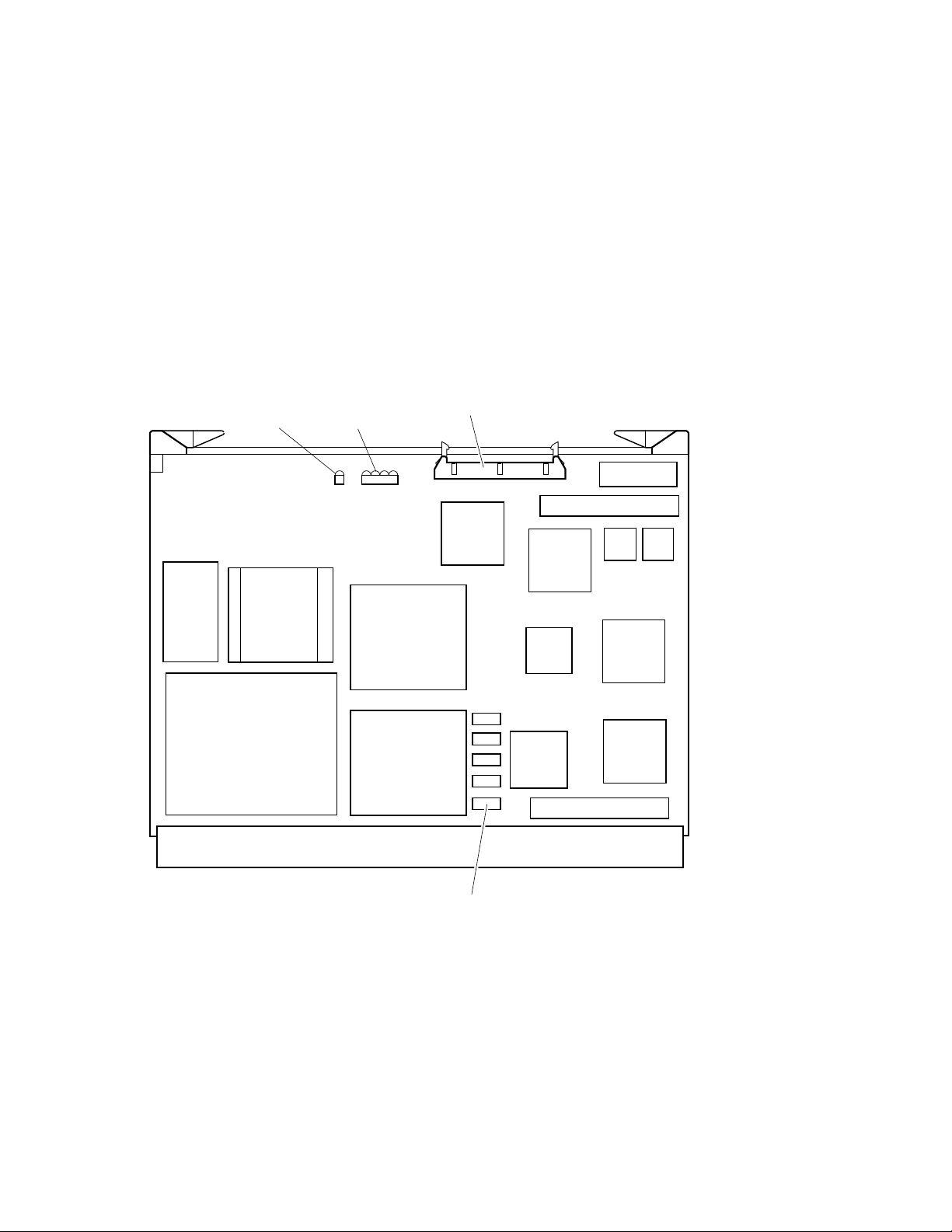
Figure 2–1 KA681/KA691/KA692/KA694 CPU Module Component Side
Console Connector, J2
BCache
(Tag
Store)
Run LED
DC246
NVAX
Diagnostic LEDs
DC243
NCA
DC541
SGEC
E-Net ROM
CDAL 2 Connector
DC542
SHAC
CLK
DC511
Firmware
ROMs
SSC
B-CACHE
(Data Store)
Backplane Connector, J1
DC244
NMC
Obit Rams
DC527
CQBIC
CDAL 1 Connector
DC542
SHAC
MLO-010827
CPU System Overview 2–3
Page 26

CPU System Overview
2.1 CPU Module Features
Table 2–1 KA681/KA691/KA692/KA694 CPU Module Components
Components Function
DC246 (NVAX) Central processor unit. Contains a 64-entry translation buffer
KA694: Central processor unit has 9-ns cycle time.)
Backup cache RAMs KA681: 128-KB backup cache (B-cache).
KA694: 2-MB backup cache (B-cache).)
DC243 (NCA) NDAL to CDAL I/O bus interface chip.
DC244 (NMC) Main memory controller (also provides ECC protection).
DC527 (CQBIC) Q22–bus interface.
DC541 (SGEC) Ethernet interface.
Ethernet Station Address ROM Provides unique hardware address.
DC542 (SHAC) DSSI interface chips (2).
DC511 (SSC) System support chip.
DC509 (CLK) Clock.
Firmware ROMs Two resident firmware chips, each 256 K by 8 bits of FLASH
Obit RAMs The ECC protected ownership-bit RAMs provide coherency
Console connector 100-pin for connection to the H3604 console module (J2).
Backplane connector 270-pin for connection to backplane for Q22–bus, DSSI bus,
Run LED Indicates that the CPU module is receiving power.
Diagnostic LEDs A hexadecimal value displays on the four diagnostic LEDs.
integral floating-point unit, 2-KB virtual instruction stream
cache (VIC), 8-KB physical instruction and data stream
primary cache (P-cache), and backup cache control and error
correction code (ECC).
KA681: Central processor unit has 14-ns cycle time.
KA691: Central processor unit has 12-ns cycle time.
KA692: Central processor unit has 10-ns cycle time.
KA691: 512-KB backup cache (B-cache).
KA692: 2-MB backup cache (B-cache).
programmable EPROMS for a total of 512 KB.
between backup cache and memory.
and memory interconnect (J1).
The values correspond to the decimal value displayed on the
H3604 console module LED.
2–4 CPU System Overview
Page 27
CPU System Overview
2.1 CPU Module Features
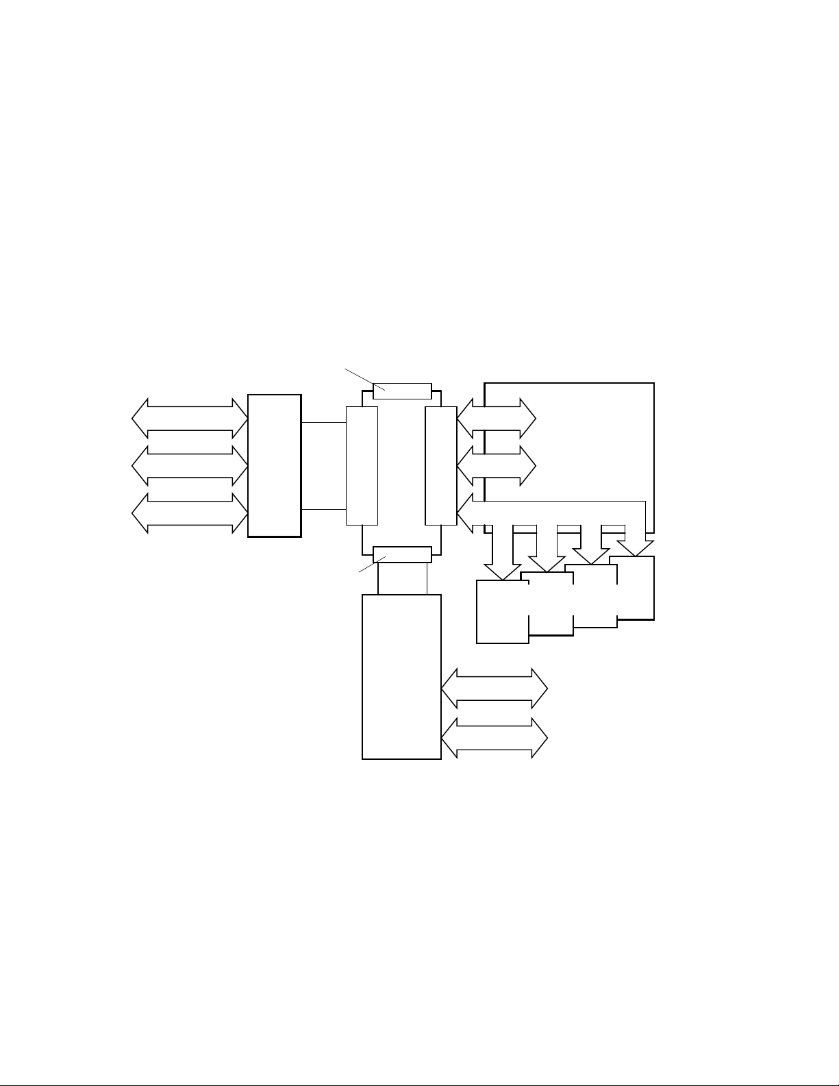
Figure 2–2 KA681/KA691/KA692/KA694 Kernel System Functional Diagram
CDAL 2 Connector
(96-Pin)
Backplane Interconnect
DSSI Bus #1
Ethernet
Serial Line
H3604
Console
Module
CDAL 1 Connector
(96-Pin)
Ribbon
Cable
Console Connector
(100-Pin)
CPU
Module
DSSI
Daughter
Board
Backplane Connector
DSSI Bus #0
(270-Pin)
Q22-bus
NMI Bus (150-Pin)
MS690 Memory Modules
(1 minimum/4 maximum)
DSSI Bus #2
DSSI Bus #3
To Mass Storage
Slots
To Q22-bus Slots
MLO-010206
CPU System Overview 2–5
Page 28
CPU System Overview
2.1 CPU Module Features
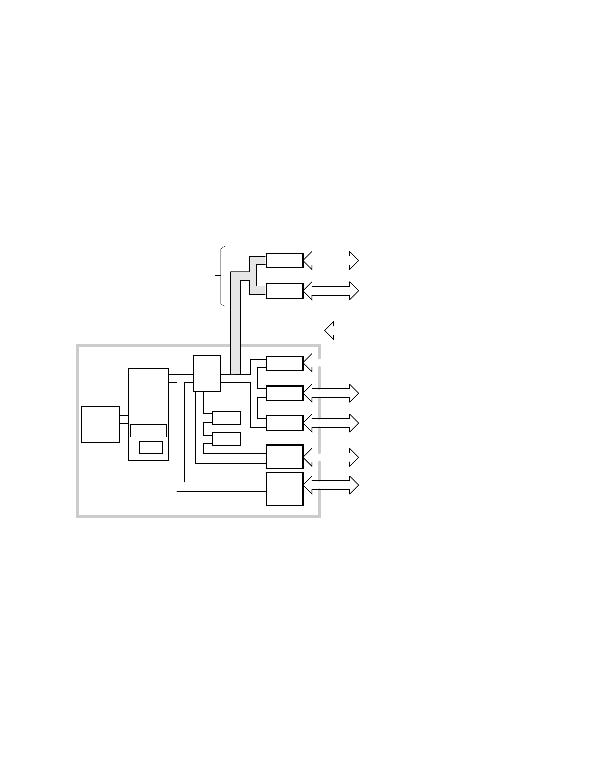
Figure 2–3 KA681/KA691/KA692/KA694 CPU Module Block Diagram
B-cache
Optional
via
KFDDB DSSI
Daughter Board
NVAX
CPU
P-cache
VIC
NDAL
NCA
CDAL 1
SSC
ROM
CDAL 2
SHAC3
SHAC4
To Console Module
SHAC1
SHAC2
SGEC
CQBIC
NMC
DSSI #2
DSSI #3
DSSI #1
DSSI #0
Ethernet
Q22-bus
To Memory
To QBus
Bukkhead
To QBus
Bukkhead
To BA440
Disks
To Console
Module
To BA440
Backplane
MLO-007262
2.2 MS690 Memory Modules
The MS690 memory module is a double-sided, quad-height memory board that
uses a 150-pin, high-density connector to communicate to the CPU module.
MS690 memory modules are ECC protected via the NMC chip on the CPU
module.
The MS690 memories are available in four variations:
• MS690–BA (L4004–BA) 32 MB memory (not used on KA692 or KA694)
• MS690–CA (L4004–CA) 64 MB memory
• MS690–DA (L4004–DA) 128 MB memory
2–6 CPU System Overview
Page 29
CPU System Overview
2.2 MS690 Memory Modules
KA681/KA691/KA692/KA694-based systems allow for any combination of up to
four MS690 memory arrays providing a memory capacity from 32 Mbytes up to
512 Mbytes, with the exception that the MS690-BA may not be used with the
KA692 or KA694.
Figure 2–4 shows a sample memory module, which, like the CPU module,
uses ejector handles designed to ensure proper seating of the modules in the
backplane connectors.
Figure 2–4 Ratchet Handles for CPU and Memory Modules
Ejector
Handles
2.3 (Optional) DSSI Daughter Board
KA681/KA691/KA692/KA694-based systems have a connector for an optional
DSSI bus daughter board. The optional DSSI daughter board contains two
SHAC chips which increase the CPU’s total DSSI bus capability to four ports.
See Figure 2–5 for a view of the major chips and connectors. Table 2–2
describes the DSSI bus daughter board components and their functions.
MLO-004227
CPU System Overview 2–7
Page 30

CPU System Overview
2.3 (Optional) DSSI Daughter Board
Figure 2–5 (Optional) DSSI Module Component Side
Bus 3
DSSI Connector
DSSI 3
Terminator
Sockets
DC542
SHAC
DC542
SHAC
Bus 2
DSSI Connector
DSSI 2
Terminator
Sockets
96-Pin
Mother Board
Connector
2–8 CPU System Overview
MLO-010209
Page 31

Table 2–2 (Optional) DSSI Bus Daughter Board Components
Components Function
DC542 (SHAC) DSSI interface chips (2).
Bus 2 DSSI connector Connect DSSI bus 2 here.
Bus 3 DSSI connector Connect DSSI bus 3 here.
DSSI Bus 2 terminator sockets Reserved for future use.
DSSI Bus 3 terminator sockets Reserved for future use.
96-pin mother board connector Connects to mother board.
2.4 BA440 Enclosure Components
KA681/KA691/KA692/KA694-based systems use the BA440 enclosure. A brief
description of the components that make up the BA440 enclosure follows.
For information on FRU removal and replacement procedures refer to the
BA430/BA440 Enclosure Maintenance manual.
2.4.1 H3604 Console Module
The H3604 console module covers the five slots dedicated to the CPU and
memory modules (one slot for the KA681/KA691/KA692/KA694, and four
available slots for MS690 memory modules). Switches on the console module
allow you to configure the kernel. The console module also provides the
connectors for a serial line console device, an external DSSI bus, and the
Ethernet. See Figures 2–6 and 2–7.
CPU System Overview
2.3 (Optional) DSSI Daughter Board
CPU System Overview 2–9
Page 32

CPU System Overview
2.4 BA440 Enclosure Components
Figure 2–6 H3604 Console Module (Front)
Console Module
Power-Up
Mode Switch
Baud Rate
Select Switch
LED Display
DSSI
Connectors
(External Bus,
Bus 1)
Baud
300___________0
600___________1
1200__________2
2400__________3
4800__________4
9600__________5
19200_________6
38400_________7
X
Bus 0
Y
Console Jack
Break Enable/
Disable Switch
Bus 1
Bus Node
ID Plugs
Ethernet
Connector
Switch
Standard
Ethernet
Connector
ThinWire
Ethernet
Connector
2–10 CPU System Overview
MLO-006350
Page 33

CPU System Overview
2.4 BA440 Enclosure Components
The front of the console module has the components listed in Table 2–3.
Table 2–3 H3604 Console Module Controls and Indicators
Control/Indicator Function
Power-Up Mode Switch This three-position rotary switch determines how
Baud Rate Select switch The Baud Rate Select switch is used to set the
Console serial MMJ connector This console terminal connector provides the RS–
the system responds at power-up.
Language Inquiry Mode (in the top position,
indicated by a profile of a face) causes the system
to display a language selection menu at power-up
if the console terminal has multinational character
set (MCS) support. Also, if a default boot device
has not been selected, this mode causes the system
to issue a list of bootable devices and prompts you
to select a device from the list. Once a device is
selected, the system autoboots from that device
each time you turn it on.
Run Mode (in the middle position, indicated by an
arrow) is the normal operating setting.
Loopback Test Mode (in the bottom position,
indicated by a T in a circle) causes the system
to run loopback tests on the console serial line at
power-up.
system’s baud rate to match that of the console
terminal. The factory setting is position 5 (9600).
423 interface for the console terminal.
LED Display The LED displays the testing sequence during
power-up.
(continued on next page)
CPU System Overview 2–11
Page 34

CPU System Overview
2.4 BA440 Enclosure Components
Table 2–3 (Cont.) H3604 Console Module Controls and Indicators
Control/Indicator Function
Break Enable/Disable switch When the switch is down (position 0), breaks are
Two DSSI bus node ID plugs KA681/KA691/KA692/KA694-based systems have
disabled. When the switch is up (position 1), breaks
are enabled. When breaks are enabled, pressing
Break
on the console terminal halts the processor
and transfers control to the console program. Using
the console command SET CONTROLP, you can
specify the control character,
Break
to initiate a break signal.
The Break Enable/Disable switch also controls
what happens at power-up. When breaks are
disabled (down, position 0), the system attempts
to automatically boot software at power-up. When
breaks are enabled (up, position 1), the system
enters console mode (indicated by the >>>prompt)
at power-up.
Using the console command, SET HALT REBOOT
or SET HALT RESTART_REBOOT, you can set
your system to automatically boot software after
the system is halted due to pressing
two separate Digital Storage Systems Interconnect
(DSSI) buses. Two DSSI bus node ID plugs, one
for the internal DSSI bus, Bus 0, and one for the
external bus, Bus 1, identify the bus nodes of the
DSSI adapters, which are part of the CPU.
Ctrl/P
, rather than
Break
.
Two DSSI connectors for Bus 1 Two in/out DSSI connectors, labeled X and Y, on the
2–12 CPU System Overview
console module allow you to expand the system by
connecting additional mass storage devices to the
second DSSI bus. You can also share mass storage
devices with another system by forming a DSSI
VAXcluster configuration.
(continued on next page)
Page 35

CPU System Overview
2.4 BA440 Enclosure Components
Table 2–3 (Cont.) H3604 Console Module Controls and Indicators
Control/Indicator Function
Ethernet port features The console module has two Ethernet connectors:
a BNC-type connector for ThinWire Ethernet,
and a 15-pin connector for a standard Ethernet
transceiver cable. The Ethernet connector switch
allows you to set the type of connection. To use
the standard transceiver cable connection, set the
switch to the up position. To use the ThinWire cable
connection, set the switch to the down position. A
green indicator light (LED) for each connector
indicates which connection is active.
Figure 2–7 H3604 Console Module (Back)
Battery Backup Unit
W2
W4
J1
J1 = TOY Clock Battery
J5 = H3604 Power
J6
F2
F1F4
J5
F3
J6 = CPU Interface
W2 = Remote Boot Enable
W4 = FEPROM Write Enable
F1 = ThinWire Ethernet Power, 0.5 A
PN = 12-09159-00
F2 = -12V Power, 0.062 A
PN = 90-09122-00
F3 = DSSI Terminator Power, 2.0 A
PN = 12-10929-06
F4 = Standard Ethernet Power, 1.5 A
PN = 12-10929-08
MLO-006351
CPU System Overview 2–13
Page 36

CPU System Overview
2.4 BA440 Enclosure Components
The back of the console module has the components listed in Table 2–4.
Table 2–4 H3604 Console Module (Back)
Component Function
Battery Backup Unit Provides battery backup power to the SSC
TOY Clock Battery connector (J1) Provides the connection between the
H3604 power connector (J5) Four-pin power connector to power harness
CPU Interface connector (J6) 100-pin connector to the CPU module.
ThinWire Ethernet Power Fuse (F1) Protects ThinWire Ethernet.
-12 V Power Fuse (F2) Protects console serial line.
DSSI Terminator Power Fuse (F3) Protects against shorts from the accidental
Standard Ethernet Power Fuse (F4) Protects Standard Ethernet.
Remote Boot Enable jumper (W2) Not used
RAM.
battery backup unit and the SSC RAM.
module.
grounding of the DSSI cable power pin.
FEPROM Write Enable jumper (W4) This jumper must be in the write enable
-9 V DC/DC converter Generates voltage for the Ethernet
2–14 CPU System Overview
position to update FEPROMs on the CPU
module. Refer to Chapter 6 for procedures
on updating ROMs.
transceiver.
(continued on next page)
Page 37

2.4 BA440 Enclosure Components
Table 2–4 (Cont.) H3604 Console Module (Back)
Component Function
CPU System Overview
Ethernet serial transceiver chip
Serial Interface Adapter (SIA)
TOY clock oscillator Time of year oscillator. Privides TOY signal
Performs Ethernet serial transactions.
for the TOY clock in the system support
chip (SSC) on the CPU module.
CPU System Overview 2–15
Page 38

CPU System Overview
2.4 BA440 Enclosure Components
2.4.2 System Control Panel (SCP)
The system control panel (SCP) (Figure 2–8) provides the controls to halt the
processor (external halt type) and enter console mode, as well as to restart the
system and return the processor state to power-up and self tests.
Figure 2–8 System Control Panel
Over Temperature
Warning Indicator
DC OK Indicator
Halt Button
Restart Button
2–16 CPU System Overview
MLO-008652
Page 39

CPU System Overview
2.4 BA440 Enclosure Components
The SCP has the controls and indicators listed in Table 2–5.
Table 2–5 System Control Panel Controls and Indicators
Control/Indicator Function
Over Temperature Warning
indicator
DC OK indicator The green DC OK indicator shows that the power
Halt Button The Halt button is a two-position button. When you
The red Over Temperature Warning indicator
flashes to indicate that the system’s internal
temperature is approaching a level that may cause
system components to overheat. In addition to the
flashing Over Temperature Warning indicator, an
audible alarm also provides warning of a possible
over temperature condition. If the components
continue to heat, the system will automatically shut
down to prevent components from being damaged.
supply voltages are within the correct operating
range.
press the button, the system halts. A red indicator
on the Halt button lights when the button is set
to the in position. Before you can enter console
commands, press the Halt button again to return
it to the out position. When the Halt button is
returned to the out position, the console mode
prompt >>> is displayed on the console terminal
screen. Now you can enter console commands. If
you inadvertently press the Halt button, type ‘‘c
Return
’’ to continue.
Caution
Pressing the Halt button halts
the system regardless of the
setting of the Break Enable
/Disable switch on the console
module.
(continued on next page)
CPU System Overview 2–17
Page 40

CPU System Overview
2.4 BA440 Enclosure Components
Table 2–5 (Cont.) System Control Panel Controls and Indicators
Control/Indicator Function
Restart Button The Restart button has a green indicator. When
you press the Restart button, the system returns to
a power-up condition and self-tests are run. If you
have specified a device as the boot device and if the
Break/Enable Disable switch is set to disable, the
system will reboot system software.
2–18 CPU System Overview
Page 41

2.4.3 BA440 Backplane
KA681/KA691/KA692/KA694-based systems use the BA440 (54–19354–01)
backplane, shown in Figure 2–9.
Figure 2–9 BA440 Backplane
Mass Storage
Connectors
CPU System Overview
2.4 BA440 Enclosure Components
Vterm Module
SCP
Connector
Module
Connectors
1110 9 8 7 6 4 3 2
12
Q-bus
Option
5
CPU
Power
Board
for H3604
Power Supply
Connectors
1
Fan Connector
Memory
MLO-007695
CPU System Overview 2–19
Page 42

CPU System Overview
2.4 BA440 Enclosure Components
2.4.4 Power Supply
The BA440 enclosure uses the H7874 power supply (Figure 2–10). Table 2–6
describes the power supply components.
Figure 2–10 H7874 Power Supply
Power Switch
AC Present Indicator
DC OK Indicator
Fan Failure
Indicator
Over Temperature
Condition Indicator
Power Bus
Connectors
2–20 CPU System Overview
Power Cable
Connector
MLO-004040
Page 43

CPU System Overview
2.4 BA440 Enclosure Components
Table 2–6 H7874 Power Supply Switches, Controls, and Indicators
Control/Indicator Function
AC Present indicator (orange) Lights when the Power switch is set to on (1), and
Power switch The Power switch is used to turn system power on
DC OK indicator (green) When the DC OK indicator is lit, the voltages are
Fan Failure indicator (amber) The Fan Failure indicator lights if either of the
Over Temperature indicator
(amber)
the ac voltage is present at the input of the power
supply.
and off. The off position is indicated by a 0; the on
position is indicated by a 1.
The Power switch also functions as the system
circuit breaker. In the event of a power surge, the
breaker will trip causing the power switch to return
to the off position (0). Turning on the system resets
the circuit breaker. If the circuit breaker trips, wait
one minute before turning the system back on.
within the correct operating range. An unlit DC OK
indicator shows a problem with the power supply.
two cooling fans stops working. The power supply
will automatically shut down the system as a
precautionary measure when a fan failure is
detected.
The Over Temperature indicator lights if the
system has shut down due to an over temperature
condition.
(continued on next page)
CPU System Overview 2–21
Page 44

CPU System Overview
2.4 BA440 Enclosure Components
Table 2–6 (Cont.) H7874 Power Supply Switches, Controls, and Indicators
Control/Indicator Function
Power bus connectors Three power bus connectors allow you to configure
a power bus for systems expanded with a system
expander. The power bus allows you to turn power
on and off for the system through one power supply
designated as the main power supply: this way, one
power switch can control power for an expanded
system.
Note
DSSI VAXcluster systems
should not be configured with
a power bus. Inadvertently
shutting off a host system
and bringing down the cluster
defeats the added reliability of
a DSSI VAXcluster.
MO The main out connector sends the power control
bus signal to the expander. One end of a power bus
cable is connected here; the other end is connected
to the SI (secondary in) connector of the expander
power supply.
SI The secondary in connector receives the power bus
SO The secondary out connector sends the signal down
2–22 CPU System Overview
control signal from the main power supply. In a
power bus with more than one expander, the power
bus signal is passed along using the secondary in
and out connectors.
the power bus for configurations of more than one
expander.
Page 45

2.4.5 System Airflow
Two fans are located under the card cage (Figure 2–11). The power supply
monitors the fans. If either fan stops working, the Fan Failure indicator
on the power supply lights, and the system automatically shuts down as a
precautionary measure.
Figure 2–11 Fans
CPU System Overview
2.4 BA440 Enclosure Components
Captive Screws
MLO-004220
Some system managers request that the fans run at the maximum rate
at all times to take advantage of a potential increase in system reliability.
The system environment must not exceed the limits described in the Site
Preparation manual. Figure 2–12 shows the location of the fan speed control
(FSC) jumper on the bottom of the power supply. Setting the FSC jumper to
disable causes the fans to run at the maximum rate.
CPU System Overview 2–23
Page 46

CPU System Overview
2.4 BA440 Enclosure Components
Figure 2–12 Fan Speed Control (FSC) Jumper Location
FSC
Enabled
(Factory
Setting)
FSC
Disabled
2–24 CPU System Overview
MLO-004204
Page 47

System Setup and Configuration
This chapter describes the guidelines for the configuration of a KA681/KA691
/KA692/KA694-based system. Configuration issues covered in this chapter
include module order, mass storage configurations, system expansion, DSSI
VAXcluster configurations, and firmware commands and utilities used in
system configuration.
3.1 CPU and Memory Module Order
The five right-most BA440 backplane slots are dedicated to CPU and memory
modules. The number and type of option modules installed in slots 6 through
12 depend on your configuration. If you only have two DSSI ports, then slots
6 through 12 are available for Q–bus option modules. If your system has
four CPU DSSI ports, then slots 6 through 10 are available for Q–bus option
modules and slots 11 and 12 are DSSI bus bulkheads. See Table 3–1.
Table 3–1 BA440 Module Order
Slot Module
3
1 through 4 Reserved for up to four MS690 memory modules. MS690
modules are installed from left to right with no gaps: first
memory module in slot 4, second memory module in slot 3,
and so on.
Note
Proper placement of memory modules
is necessary for FRU isolation using
error logs.
(continued on next page)
System Setup and Configuration 3–1
Page 48

System Setup and Configuration
3.1 CPU and Memory Module Order
Table 3–1 (Cont.) BA440 Module Order
Slot Module
5 CPU module: KA681 (L4005–BA), KA691 (L4005-AA),
6 through 12 Q–bus options
OR
6 through 10 Q–bus options
11 and 12 DSSI ports
OR
6 through 9 Q–bus options
10 and 11 DSSI ports when M9404 is installed in slot 12
KA692 (L4006-AA), KA694 (L4006–BA)
A system can have up to four memory modules. Memory modules are available
in 32 MB (MS690–BA), 64 MB (MS690–CA), and 128 MB (MS690–DA), and
can be used in any combination. The firmware logically configures the memory
modules at power-up.
Note
The MS690–BA may not be used with the KA692 or KA694 CPU
modules.
3.1.1 Installing Add-On MS690 Memory Modules
Perform the following steps to install add-on MS690 memory module(s). You do
not set any jumpers or switches on the memory module. The memory address
for the memory module is mapped by the system.
Turn off the system before installing modules. Installing modules while
this system is powered up can damage the modules.
1. Two captive screws hold the console module (H3604) in place. To loosen,
both screws should be turned counterclockwise. The console module is
hinged on the left. Swing the assembly open.
3–2 System Setup and Configuration
Caution
Page 49

System Setup and Configuration
3.1 CPU and Memory Module Order
Note
Two cables connect to the H3604 console module: a ribbon cable which
connects to the CPU module; and a four-pin power harness connects to
a power harness module (also known as the power board H3604) which
plugs into the backplane. The power harness module is located directly
to the right of the CPU module.
2. Install the module(s) starting with the first empty slot, which is located on
the right side of the power harness module. The power harness module is
located between the CPU module (slot 5) and the first memory module (slot
4).
The memory module(s) must be installed in adjacent slots with no empty
slots between. Slots 12 through 6 are Q–bus slots, or slots 10 through 6 are
Q–bus slots and slots 12 and 11 are optional DSSI slots; slot 5 is the CPU
slot; and slots 4 through 1 are the memory module slots.
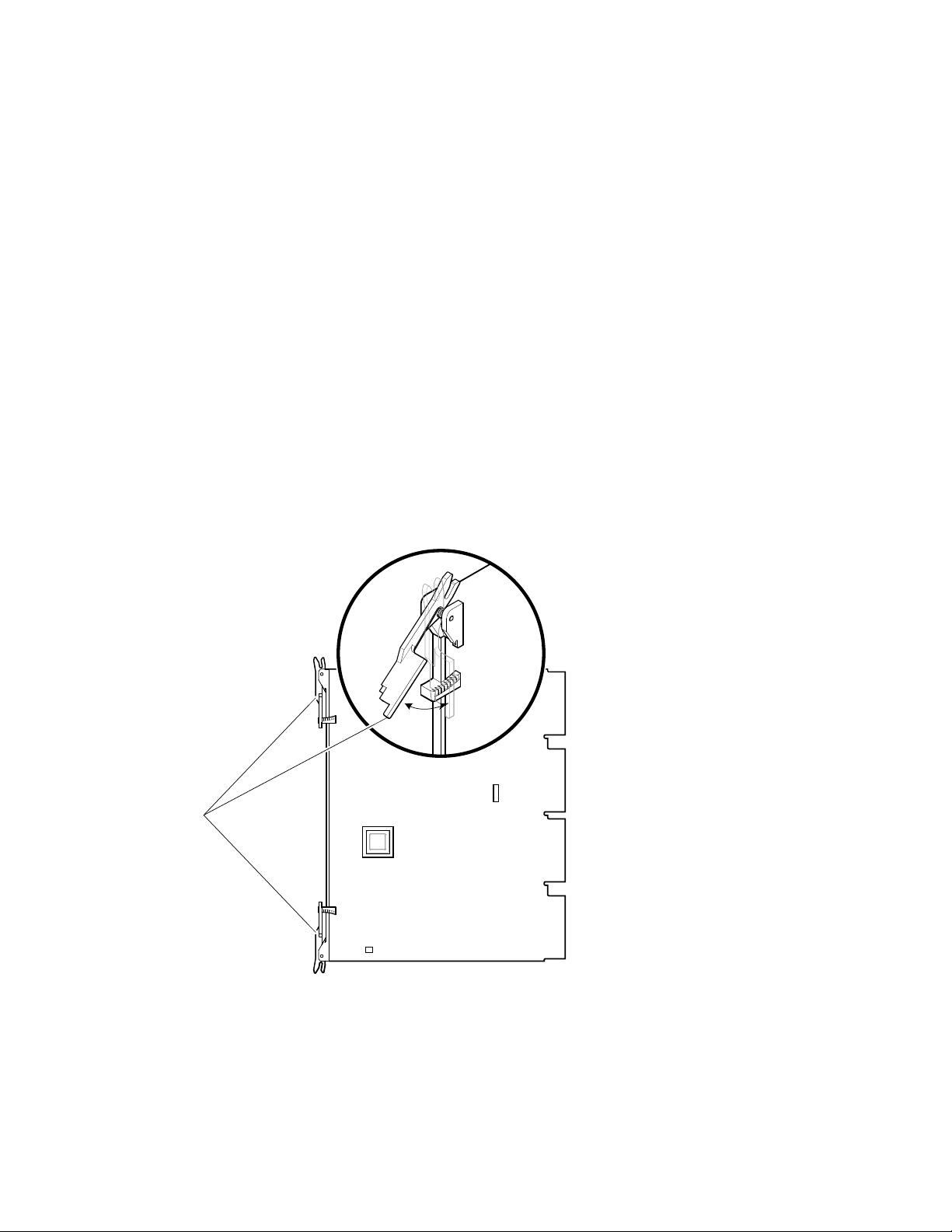
3. Make sure the ratchet handles on the memory module are on the right side
of the module.
Wearing the antistatic wrist strap, install the memory module in the first
available memory slot to the right of the CPU. Ensure that the memory
module is vertically aligned. Push the memory module in until the ratchet
handles engage with the enclosure frame. Push the ratchet handles inward
toward the rear of the cabinet until the memory module is firmly seated
in the backplane. When the memory module is firmly seated, the ratchet
handles will lock the module in place.
Note
The CPU and MS690 memory modules are equipped with ratchet
handles (Figure 3–1) which are shipped in a horizontal position. The
ratchet handles are designed to ensure that the modules are properly
seated in the backplane connectors.
4. Close the H3604 console module and lock the 1/4-turn captive screws.
5. To identify the memory module, place the MS690 option label (supplied
in the option kit) in the proper location on the H3604 panel. Indicate the
revision number and memory option (BA, CA, or DA).
System Setup and Configuration 3–3
Page 50

System Setup and Configuration
3.1 CPU and Memory Module Order
Figure 3–1 Memory Module Ratchet Handles
Ejector
Handles
MLO-008453
6. Refer to Chapter 4 for information on initialization and acceptance testing.
3.2 General Module Order for Q–Bus Options
The order of the supported Q–bus options in the backplane depends on four
factors:
• Relative use of devices in the system
• Expected performance of each device relative to other devices
• The ability of a device to tolerate delays between bus requests and bus
grants (called delay tolerance or interrupt latency)
• The tendency of a device to prevent other devices farther from the CPU
from accessing the bus
3–4 System Setup and Configuration
Page 51

System Setup and Configuration
3.2 General Module Order for Q–Bus Options
The supported options arranged by type are:
Communications
CXA16–AA/AF: 16-line DEC–423 asynchronous controller
CXB16–AA/AF: 16-line RS–422 asynchronous controller
CXY08–AA/AF: 8-line RS–232C asynchronous controller with modem
DEFQA–SA/SF: Q–bus FDDI adapter
DEFQA–DA/DF: Q–bus FDDI adapter
DEQRA–CA: Token Ring Network Controller
DESQA–SA/SF: ThinWire Ethernet adapter
DFA01–AA/AF: 2400/1200 BPS modem
DIV32–SA/SF: Q–bus ISDN basic rate access interface
DPV11–SA/SF: Q–bus synchronous programmable interface
DRV1W–SA/SF: General purpose 16-bit parallel DMA interface
DRV1J–SA/SF: Q–bus parallel interface
DSV11–SA/SF: Q–bus 2-line synchronous
KMV1A–SA/SF: Single-line programmable controller with DMA
General
ADQ32–SA/SF: 32-channel ADC module
ADV11–SA/SF: 16-channel ADC module
AXV11–SA/SF: 16-channel ADC, 2-channel DAC module
DRQ3B–SA/SF: Q–bus parallel I/O interface
DTC05–SA: Digital encoded voice, multifunction
IBQ01–SA/SF: DECscan/BITBUS controller
IEQ11–SA/SF: Dual-bit DMA serial Q–bus controller
KITHA–AA: Mira AS option
KWV11–SA/SF: Programmable real-time clock
LPV11–SA/SF: Line printer controller
MRV11: Q–bus, universal socket, 32-Kbyte EPROM
VS30U–GA/G3/G4: Graphics option
Mass Storage, Tape, Pedestal Expansions
EF51R–AA/AF: 107-Mbyte solid state storage element with data retention
EF52R–AA/AF: 205-Mbyte solid state storage element with data retention
EF53–AA/AF: 267-Mbyte solid state storage element without data retention
HSD05–JA/JF: DSSI to SCSI converter
RF35E–AA: 852-Mbyte half-height DSSI integrated storage element
RF352–AA/AF: Two RF35s for installation in one 5.25-inch storage cavity
RF36E–AA/AF: 1.6-Gbyte half-height DSSI integrated storage element
RF362–AA/AF: Two RF36s for installation in one 5.25-inch storage cavity
RF73E–AA/AF: 2.0-Gbyte full-height DSSI integrated storage element
RF72E–AA/AF: 1.0-Gbyte full-height DSSI integrated storage element
System Setup and Configuration 3–5
Page 52

System Setup and Configuration
3.2 General Module Order for Q–Bus Options
RF71E–AA/AF: 400-Mbyte full-height DSSI integrated storage element
RF31E–AA/AF: 381-Mbyte half-height DSSI integrated storage element
RF31T–AA/AF: 381-Mbyte full-height DSSI integrated storage element
RF74E–AA/AF: 3.75-Gbyte full-height DSSI integrated storage element
TF85E–JA/JF: 2.6-Gbyte DSSI integrated storage element with 5.25-inch
cartridge
TF85–TA: 3.75-Gbyte DSSI tape drive in table top enclosure
TF86E–JA/JF: 6.0-Gbyte DSSI tape driver ISE for BA400-series 5.25-inch
storage cavity
TLZ04–JA/JF/GA: 1.2-Gbyte cassette (DAT) tape drive (requires KZQSA
storage adapter)
TLZ06–GA: 2.0-/4.0-Gbyte tabletop 4mm DAT drive (requires KEQSA SCSI
adapter)
TK70E–AA/AF/TQK70–SA/SF: 5.25-inch cartridge, 296-Mbyte tape drive,
tape controller
TK50E–AA/AF/TQK50–SA/SF: 5.25-inch cartridge, 95-Mbyte tape drive,
tape controller
KLESI–SA: Q–bus to LESI adapter
KFQSA–SE/SG: DSSI Q–bus adapter
KZQSA–SA/SF: Storage adapter for TLZ04 tape drive and RRD42 compact
disc drive
RA81/82: Storage array (separate cabinets only)
RA90/92: Storage array (separate cabinets only)
KDA50–SE/SG: SDI Q–bus adapter
KRQ50–SA/SF: Q–bus controller for RRD40–DC
TU81E–SA/SB: Magnetic tape (requires KLESI controller)
TSV05–SE/SF/SH/SJ: Q–bus TS05 magnetic tape controller
B400X: Expansion box with 10 Q–bus slots and up to 4 ISEs
R400X–B9: Expansion box with up to 7 RF-series ISEs
RRD40: 600-Mbyte CDROM tabletop drive (requires KRQ50 controller)
RRD42: 600-Mbyte tabletop compact disc drive (requires KZQSA storage
adapter)
RSV20–A: WORM optical drive subsystem (requires KLESI controller)
RWZ01: 594-Mbyte Magneto-Optical Disc (requires KZQSA storage
adapter)
ESE20: Electronic storage element (requires KDA50 controller)
3–6 System Setup and Configuration
Page 53

System Setup and Configuration
3.3 Recommended Module Order of Q-Bus Options
3.3 Recommended Module Order of Q-Bus Options
The recommended module order for placement of Q–bus options is provided in
the following list:
MRV11 (Placement not critical)
AAV11
ADV11
AXV11
KWV11
DRV1J
KMV1A
DEQRA
DESQA
DEFQA
DPV11
DIV32
VS3OU
DFA01
CXA16
CXY08
CXB16
LPV11
DRV1W
KRQ50
IEQ11
ADQ32
DRQ3B
DSV11
KLESI
IBQ01
TSV05 (M7530 controller)
KDA50–SE
KFQSA–SE
KZQSA
TQK50
TQK70
M9060–YA
System Setup and Configuration 3–7
Page 54

System Setup and Configuration
3.4 (Optional) DSSI Ports Assignment
3.4 (Optional) DSSI Ports Assignment
The last two slots in the BA440 enclosure will contain DSSI bulkheads if
ordered. Slot 11 is assigned Bus 2 and slot 12 is Bus 3.
3.5 Mass Storage Options (Internal)
The mass storage shelf of a BA440 enclosure provides four storage cavities
for embedded mass storage options. The rightmost storage cavity can contain
a tape drive (TF85/TF86, TK-series, or TLZ04); all four storage cavities can
contain an EF/RF-series ISE.
Combinations of dual-disk, single-disk, or tape ISEs can be used to gain the
full complement of seven DSSI devices on the internal DSSI bus (Bus 0).
VAX 4000 Model 500A/505A/600A/700A/705A systems can support the following
combinations of mass storage options embedded in the system enclosure:
• One tape drive (TF85/TF86, TK-series, or TLZ04) and up to six EF
/RF-series ISEs using the dual-disk RF35.
• No tape drive and up to seven RF-series ISEs using the dual-disk RF35.
Note
The RF35, which has dual-disk capability, can be ordered with a single
disk.
Figure 3–2 shows an example of a mass storage configuration consisting of a
TF85/TF86 tape drive, two RF35s, and two RF73s.
Rules for Numbering Storage Devices
Use the rules below for numbering (bus node ID and MSCP unit numbers)
storage devices:
• For each DSSI bus, do not duplicate bus node ID numbers for your storage
devices/adapter. For Bus 0, you can have only one storage device identified
as bus node 0, one storage device as 1, and so on; for Bus 1, you can have
only one storage device identified as bus node 0, one storage device as 1,
and so on.
• The previous rule also applies to DSSI VAXcluster configurations; all DSSI
bus node numbers for storage devices and DSSI adapters must be unique
in a shared DSSI bus.
3–8 System Setup and Configuration
Page 55

System Setup and Configuration
3.5 Mass Storage Options (Internal)
Figure 3–2 Storage Configuration Example
ISE 3 ISE 2 ISE 1 and 0 Tape Drive
MLO-007696
• By convention, the EF/RF-series ISEs are numbered in increasing order
from right to left beginning with zero.
• DSSI adapters use the highest available bus nodes. The next highest
available bus node (usually five) is reserved for the TF-series tape drive.
• When more than one DSSI bus is being used and the system is using
a nonzero allocation class, you need to assign new MSCP unit numbers
for devices on all but one of the DSSI buses since the unit numbers for
all DSSI devices connected to a system’s associated DSSI buses must be
unique. Refer to Section 3.8.3 for more information on setting parameters
for DSSI devices.
Note
If you change the bus node ID plugs, power down the system, change
the plugs and then power up the system.
System Setup and Configuration 3–9
Page 56

System Setup and Configuration
3.6 System Expansion
3.6 System Expansion
The mass storage and Q–bus capacity of VAX 4000 Model 500A/505A/600A
/700A/705A systems can be increased using the following expanders.
3.6.1 Mass Storage Expanders
• The R400X mass storage expander provides space for up to seven additional
EF/RF-series ISEs or up to six EF/RF-series ISEs and a tape drive (TF85
/TF86 or TLZ04). Using R400X expanders, you can fill both DSSI buses for
a total of 14 DSSI mass storage devices.
Using the dual-disk RF35, the R400X can accommodate up to 13 ISEs.
Note
3–10 System Setup and Configuration
Page 57

• The R215F expander provides space for up to three EF/RF-series ISEs.
This does not include the RF74.
Using the dual-disk RF35, you can increase the number of ISEs—up to
seven ISEs per DSSI bus.
• The SF100 storage array pedestal provides space for a TF857 magazine
tape subsystem and one SFxx storage array building block.
• The SF200 storage array subsystem provides space for up to two TF857
magazine tape subsystems and up to six SFxx storage array building
blocks.
• The SF12 is a desktop DSSI expander providing four 3.5-inch storage slots.
3.6.2 Q–Bus Expanders
• The B400X expander provides 10 additional usable Q–bus slots for a
system total of 17 usable Q–bus slots. The B400X also has space for up
to four additional EF/RF-series ISEs or up to three ISEs and a tape drive
(TF85/TF86, TK70, or TLZ04).
System Setup and Configuration
3.6 System Expansion
Note
Note
Using the dual-disk RF35, the B400X can accommodate up to seven
ISEs.
• The B213F expander also provides 10 additional usable Q–bus slots and
provides space for up to three EF/RF-series ISEs or up to three ISEs and a
TK-series tape drive.
Note
Installing a B213F or R215F on a VAX 4000 system requires the
H4010–AA expander cable kit.
System Setup and Configuration 3–11
Page 58

System Setup and Configuration
3.6 System Expansion
3.6.3 Control Power Bus for Expanders
The three power bus connectors on the H7874 power supply allow you to
configure a power bus for systems expanded with R400X and B400X expanders.
The power bus allows you to turn power on and off for one or more expanders
through the power supply designated as the main power supply (Figure 3–3).
Note
DSSI VAXcluster systems should not be configured with a power bus.
Inadvertently bringing down the cluster defeats the added reliability of
a DSSI VAXcluster.
Figure 3–3 Sample Power Bus Configuration
System Expander 1 Expander 2
3–12 System Setup and Configuration
MLO-004041
Page 59

System Setup and Configuration
3.6.4 Adding Options to the System Enclosure
To determine what options you can add to the system enclosure, you must
list the options currently installed and their power requirements on the VAX
4000 Model 500A/505A/600A/700A/705A Configuration Worksheet, provided in
Figure 3–4.
The worksheet in Figure 3–4 is for the BA440 enclosure. All backplane slots
and mass storage devices are powered by the H7874 power supply.
Use the worksheets as follows:
1. In the Module column, list all options and mass storage devices currently
installed in your system. The CPU module has already been entered.
Use the label on the cover panel of each slot to identify the module installed
in that slot.
2. List each embedded storage device.
3. List the options and mass storage devices you wish to add to your system.
4. If the system includes a TK50 or TK70 tape drive, list the TQK70 controller
last.
5. Fill in the power requirements for each module and each mass storage
device. The power requirements for the more common options are listed in
Table 3–2.
3.6 System Expansion
6. Add each column and make sure the totals do not exceed the specified
limit.
System Setup and Configuration 3–13
Page 60

System Setup and Configuration
3.6 System Expansion
Figure 3–4 VAX 4000 Model 500A/505A/600A/700A/705A Configuration
Worksheet
MEM 1
MEM 2
MEM 3
MEM 4
2
2
2
L4002-nA
L4005-nA
L4006-nA
CPU
CPU
CPU
Q-bus 1
Q-bus 2
Q-bus 3
Q-bus 4
Q-bus 5
Q-bus 6
Q-bus 7
Mass Storage:
Tape
1
2
3
4
Total these columns:
Must not exceed:
ModuleSlot
+5 Vdc
3
4.8
4
9.084
5
8.6
60.0 A
Current (Amps)
+12 Vdc
1.6 3.2 0.0
1.6
1.6
22.0 A 584.0 W
15.0 A 3.0 A 31
1
-12 Vdc+3.3 Vdc
Power
(Watts)
53.8
64.62
62.2
Bus Load
AC DC
4.0 1.0
4.0 1.0
4.0 1.0
20
Total output power from +3.3 Vdc and +5 Vdc must not exceed 330 watts.
1.
2. Power requirements in this line include CPU module, H3604 console module,
and backplane terminator combined.
3. KA690(L4002-AA), KA680(L4002-BA), or KA675(L4002-CA)
4. KA681 (L4005-BA) or KA691 (L4005-AA)
5. KA692 (L4006-AA)
6. KA694 (L4006-BA)
3–14 System Setup and Configuration
MLO-005361
Page 61

System Setup and Configuration
3.6 System Expansion
Table 3–2 Power Requirements
Current (Amps)
Option Module +5 V +12 V Watts AC DC
AAV11–SA A1009–PA 2.10 0.00 10.50 2.5 0.5
ADQ32–SA A030 4.45 0.00 22.25 2.5 0.5
ADV11–SA A1008–PA 2.00 0.00 10.00 2.3 0.5
AXV11–SA A026–PA 2.00 0.00 10.00 1.2 0.3
CXA16–AA M3118–YA 1.60 0.20 10.40 3.0 0.5
CXB16–AA M3118–YB 2.00 0.00 10.00 3.3 0.5
CXY08–AA M3119–YA 1.64 0.395 12.94 3.0 0.5
DEFQA–DA M7534–AD 5.60 0.1 31.0 4.9 1.5
DESQA–SA M3127–PA 2.40 0.22 14.64 3.3 0.5
DEQRA–CA M7533–AB 4.0 1.0 21.20 2.2 0.5
DFA01–AA M3121–PA 1.97 0.04 10.30 3.0 1.0
DIV32–SA M7571–PA 5.5 0.00 35.4 3.5 1.0
DPV11–SA M8020–PA 1.20 0.30 9.60 1.0 1.0
DRQ3B–SA M7658–PA 4.50 0.00 22.50 2.0 0.5
DRV1J–SA M8049–PA 1.80 0.00 9.00 2.0 1.0
DRV1W–SA M7651–PA 1.80 0.00 9.00 2.0 1.0
DSV11–SA M3108 5.43 0.69 35.43 3.9 1.0
DTC05–SA M3136 4.0 0.0 15.80 3.6 0.75
EF51R – 0.0 2.3 27.6 N/A N/A
EF52R – 0.0 2.2 26.2 N/A N/A
EF53 – 3.7 0.1 18.4 N/A N/A
1
H3604
IBQ01–SA M3125–PA 5.00 0.30 28.60 4.6 1.0
IEQ11–SA M8634–PA 3.50 0.00 17.50 2.0 1.0
KDA50–SE M7164 6.93 0.00 34.65 3.0 0.5
—– M7165 6.57 0.03 33.21 – –
– 1.70 0.50 14.50 – –
Max
Power
Max
Bus Loads
1
Also include –12 Vdc @ 0.25 A, 3 W.
(continued on next page)
System Setup and Configuration 3–15
Page 62

System Setup and Configuration
3.6 System Expansion
Table 3–2 (Cont.) Power Requirements
Current (Amps)
Option Module +5 V +12 V Watts AC DC
KFQSA–SA M7769 5.50 0.00 27.50 4.4 0.5
KLESI–SA M7740–PA 4.00 0.00 20.00 0.5 1.0
KRQ50–SA M7552 2.70 0.00 13.50 2.7 1.0
KWV11–SA M4002–PA 2.20 0.013 11.156 1.0 0.3
KXJ11–SF M7616 6.0 0.4 46.8 2.0 1.0
KZQSA–SA M5976 5.4 0.0 27.0 4.4 0.5
LPV11–SA M8086–PA 2.80 0.00 14.00 1.8 0.5
M9404–PA M9404 – 0.00 0.0 – –
M9405–PA M9405 – 0.00 0.0 – –
MRV11–D M8578 1.60
MS690–BA L4004–BA 5.03 0.00 26.5 – –
MS690–CA L4004–CA 4.2 0.00 21.0 – –
MS690–DA L4004–DA 6.4 0.00 32.0 – –
RF312–xx – 0.86(x2) 2.89(x2) 33.2 N/A N/A
RF31E–AA/AF – 1.2 2.21 32.52 N/A N/A
RF31F–AA/AF – 1.2 2.21 32.52 N/A N/A
RF31T–AA/AF – 1.71 0.85 13.7 N/A N/A
RF352–AA/AF – 1.69 5.10 33.0 N/A N/A
RF35E–AA/AF – 0.71 2.29 31.1 N/A N/A
RF362–AA – 0.86(x2) 2.89(x2) 16.6(x2) N/A N/A
RF36E–AA – 0.86 2.89 16.6 N/A N/A
RF71E–AA/AF – 1.25 1.64 25.93 N/A N/A
RF72E–AA/AF – 1.20 1.75 27.00 N/A N/A
RF73E–AA/AF – 1.20 1.75 27.00 N/A N/A
RF74E–AA – 1.0 2.5 35.0 N/A N/A
TF85E–JA/JF – 1.50 2.40 36.30 N/A N/A
Max
2
0.00 8.00 3.0 0.5
Power
Max
Bus Loads
2
Value is for the unpopulated module only.
3–16 System Setup and Configuration
(continued on next page)
Page 63

System Setup and Configuration
3.6 System Expansion
Table 3–2 (Cont.) Power Requirements
Current (Amps)
Option Module +5 V +12 V Watts AC DC
TK50E–AA – 1.50 2.40 36.30 N/A N/A
TK70E–AA/AF – 1.50 2.40 36.30 N/A N/A
TLZ04–JA/JF – 1.5 2.4 36.3 N/A N/A
TLZ06–GA/GF – 1.2 1.75 12.0 N/A N/A
TQK50–SA/SF M7546 2.9 0.00 14.5 2.8 0.5
TQK70–SA/SF M7559 3.50 0.00 17.50 4.3 0.5
TSV05–SA M7530 6.50 0.00 32.50 1.5 1.0
VCB02–A M7615 4.60 0.10 24.2 3.5 1.0
VCB02–B M7168
M7169
VCB02–C (2) M7168
M7169
8.85 0.47 49.89 3.5 1.0
12.0 0.47 65.64 3.5 1.0
Max
Power
Max
Bus Loads
3.7 DSSI VAXclusters
A DSSI VAXcluster configuration is one in which up to three systems can
access the same DSSI devices. Some failures of any system can be tolerated,
in which case the remaining system(s) continues to access all available DSSI
devices and assure continued processing. See Figure 3–5.
If one of the CPU modules fails, all satellite nodes booted through that CPU
module lose connections to the system disk. However, the DSSI VAXcluster
enables each satellite node to know that the system disk is still available
through a different path—that of the functioning CPU module. A connection
through that CPU is then established, and the satellite nodes are able to
continue operation. The entire cluster will run slower, since one CPU is now
serving the satellite nodes of both systems. Processing can continue, however,
until Digital Services can repair the problem.
System Setup and Configuration 3–17
Page 64

System Setup and Configuration
3.7 DSSI VAXclusters
Figure 3–5 DSSI Cabling for a Generic Two-System DSSI VAXcluster
Configuration
SYS0 SYS1
RFxx RFxx RFxx
Boot
Node #1
RFxx RFxx RFxx
DSSI
Boot
Node #2
Ethernet
Satellite
Node
LAT
Satellite
Node
Satellite
Node
LAT
MLO-003295
3–18 System Setup and Configuration
Page 65

A DSSI VAXcluster system cannot recover from the following conditions:
• System disk failure, which can be caused by such factors as a power supply
failure in the enclosure containing the disk.
• DSSI cabling failure, which must be repaired to continue operation.
3.7.1 DSSI VAXcluster Configuration Rules
• An Ethernet (NI)/FDDI is required on all CPU nodes.
• A DECnet license is required (at least one full function license).
• At least one common (primary) DSSI bus is required to connect with a
system disk containing system critical files.
• VAXcluster and OpenVMS license is required.
• A maximum of eight nodes per DSSI bus:
a. Each adapter or ISE (disk/tape) counts as one node.
b. A DSSI bus is a collection of all DSSI cable/path segments (inside and
outside of cabinets) between two end terminators.
c. Each node must have a unique bus node ID number (0–7).
System Setup and Configuration
3.7 DSSI VAXclusters
• A maximum of three CPUs/adapters per DSSI bus is supported.
• The DSSI bus MUST be terminated at both ends.
• The DSSI bus MUST have a common ground between all elements (CPU,
disks). The ground offset is a function of the total DSSI bus length
(terminator to terminator).
Use a voltmeter to make sure the ground offset voltage between any two
enclosures does not exceed one of the limits listed below.
Allowable Ground Offset Voltage
Total Bus Length DC AC (rms)
Up to 20 meters (65 feet)
(Office environment)
20 to 25 meters (65 to 82 feet)
(Computer room)
200 millivolts 70 millivolts
40 millivolts 14 millivolts
Total bus length includes all DSSI cable lengths, internal and external.
Refer to the DSSI VAXcluster Installation and Troubleshooting manual for
instructions on calculating internal cable lengths.
System Setup and Configuration 3–19
Page 66

System Setup and Configuration
3.7 DSSI VAXclusters
To measure the ground offset voltage, connect the voltmeter leads to bare
(unpainted) metal on each enclosure.
The ground offset voltage may vary over time if equipment is added
to the system or plugged into the power outlets. Therefore, this
measurement does not guarantee that the voltage will remain within
acceptable limits.
• Maximum single cable length is 15 m (50 ft) between connectors.
• Disconnecting the DSSI cables is NOT allowed while bus is operational.
• Number of DSSI buses per CPU:
CPU DSSI Buses
KA630 2 KFQSAs on Q–bus
KA640 1 Embedded DSSI Adapter (EDA), 2 KFQSA on Q–bus
KA650/KA655 2 KFQSAs on Q–bus
KA660 1 Embedded DSSI Adapter (EDA), 2 KFQSA on Q–bus
KA670 2 Embedded DSSI Adapters (EDAs), 2 KFQSA on Q–bus
KA675 2 Embedded DSSI Adapters (EDAs), 2 KFQSA on Q–bus
KA680 2 Embedded DSSI Adapters (EDAs), 2 KFQSA on Q–bus
KA690 2 Embedded DSSI Adapters (EDAs), 2 KFQSA on Q–bus
KA681 2 or 41Embedded DSSI Adapters (EDAs), 2 KFQSA on Q–bus
KA691 2 or 41Embedded DSSI Adapters (EDAs), 2 KFQSA on Q–bus
KA692 2 or 41Embedded DSSI Adapters (EDAs), 2 KFQSA on Q–bus
KA694 2 or 41Embedded DSSI Adapters (EDAs), 2 KFQSA on Q–bus
6xxx 6 KFMSAs per system
9000 6 KFMSAs per XMI
12 KFMSAs per system
Note
1
2 embedded DSSI adapters on the CPU module plus 2 DSSI adapters on the optional DSSI
daughter card (KFDDB).
• The minimum OpenVMS revision for DSSI VAXcluster of more than two
nodes with:
a. VAX 4000 Model 400 is OpenVMS 5.5–2
3–20 System Setup and Configuration
Page 67

System Setup and Configuration
3.7 DSSI VAXclusters
b. VAX 4000 Model 500 is OpenVMS 5.5
c. VAX 4000 Model 500A is OpenVMS 5.5–2H4
d. VAX 4000 Model 505A is OpenVMS 5.5–2H4
e. VAX 4000 Model 600 is OpenVMS 5.5–2
f. VAX 4000 Model 600A is OpenVMS 5.5–2H4
g. VAX 4000 Model 700A is OpenVMS 5.5–2H4
h. VAX 4000 Model 705A is OpenVMS 5.5–2H4
• OpenVMS 6.0 does not support any VAX 4000 platforms.
• These rules apply to Digital supplied hardware. Third party devices may
not conform to DSSI electrical specification requirements. Therefore,
bus length, ground offset, basic noise margining, and warm swap
characteristics are at risk when using third party devices.
• Like adapters should be connected together whenever possible.
• Like CPUs should be connected together whenever possible.
For more information on DSSI VAXcluster configurations, refer to the DSSI
VAXcluster Installation and Troubleshooting manual. Figure 3–6 and
Figure 3–7 show two popular DSSI VAXcluster configurations using a VAX
4000 system.
System Setup and Configuration 3–21
Page 68

System Setup and Configuration
3.7 DSSI VAXclusters
Figure 3–6 Two-System DSSI VAXcluster
System A Ststem B
1 0 2 1 0 5
23
DSSI Cables
DSSI
Adapter 1
DSSI
Adapter 0
SHAC
Bus Node 6
7
7
Shared DSSI Buses and Devices
DSSI Terminator Locations
System A System B
KAnn KAnn
SHAC
Bus Node 6
2
0 1 2 3
SHAC
Bus Node 7
1 0 5
6
6
DSSI
Adapter 0
DSSI
Adapter1
SHAC
Bus Node 7
DSSI Bus Nodes for Storage Devices in System B
DSSI Bus Nodes for Storage Devices in System A
3–22 System Setup and Configuration
MLO-008312
Page 69

System Setup and Configuration
Figure 3–7 Expanded Two-System DSSI VAXcluster
3.7 DSSI VAXclusters
System A
2 1 0 3 2 1 0
DSSI Terminator Locations
SHAC
Bus Node 6
System A System B
DSSI
Adapter 1
DSSI
Adapter 0
KAnn
System B
1 2 3
0
Expander
5 4 3
DSSI
4 5
Adapter 0
6 5 4
SHAC
Bus Node 7
KAnn
DSSI
Adapter1
SHAC
Bus Node 6
DSSI Bus Nodes for Storage Devices in Expander
DSSI Bus Nodes for Storage Devices in System A and B
1 2 3
0
System A
4 5
System B
SHAC
Bus Node 7
MLO-008663
System Setup and Configuration 3–23
Page 70

System Setup and Configuration
3.8 Firmware Commands and Utilities Used in System Configuration
3.8 Firmware Commands and Utilities Used in System
Configuration
Several commands and utilities are needed to configure a system. This
section covers commands for examining and setting system parameters,
DSSI parameters, and module addresses. For a complete listing of firmware
commands, refer to Appendix A.
3.8.1 Examining System Configuration
Several variations of the SHOW command provide a display of options and key
configuration information.
• SHOW DEVICE — Lists devices (mass storage, Ethernet, and Q–bus) in
the system. (The SHOW DEVICE command combines the information
displayed using the SHOW command with DSSI, UQSSP, SCSI, and
Ethernet.)
• SHOW DSSI — Lists all DSSI devices and their associated DSSI
parameters for embedded DSSI adapters.
• SHOW DSSI_ID — Lists the DSSI node ID for each adapter.
• SHOW ETHERNET — Lists the hardware Ethernet address for each
Ethernet adapter.
• SHOW QBUS — Lists all Q–bus devices and their I/O addresses in hex,
the address as it would appear in the Q–Bus I/O space in octal, as well as
the word data read in hex.
• SHOW SAVED_STATE — Lists the non-volatile console parameter values
stored in FEPROM.
• SHOW SCSI — Lists all SCSI devices in the system.
• SHOW SCSI_ID — Lists the SCSI node ID for each adapter.
• SHOW UQSSP — Lists all DSSI devices for KFQSA-based DSSI adapters.
• SHOW MEMORY — Lists main memory configuration for each memory
board.
3–24 System Setup and Configuration
Page 71

System Setup and Configuration
3.8 Firmware Commands and Utilities Used in System Configuration
Sample displays of some of the above commands are provided below.
>>>SHOW DEVICE
DSSI Bus 0 Node 0 (CLYDE)
-DIA0 (RF73)
DSSI Bus 0 Node 1 (BONNIE)
-DIA1 (RF73)
DSSI Bus 0 Node 5 (TFDR1)
-MIA5 (TF85/TF86)
DSSI Bus 0 Node 6 (*)
DSSI Bus 1 Node 7 (*)
UQSSP Disk Controller 0 (772150)
-DUA20 (RF31)
UQSSP Disk Controller 1 (760334)
-DUB21 (RF31)
UQSSP Disk Controller 2 (760340)
-DUC22 (RF31)
UQSSP Disk Controller 3 (760322)
-DUD23 (RF31)
UQSSP Tape Controller 0 (774500)
-MUA0 (TK70)
SCSI Adaptor 0 (761400), SCSI ID 7
-MKA0 (DEC TLZ04 1991(c)DEC)
Ethernet Adapter
-EZA0 (08-00-2B-06-10-42)
>>>SHOW DSSI
DSSI Bus 0 Node 0 (CLYDE)
-DIA0 (RF73)
DSSI Bus 0 Node 1 (BONNIE)
-DIA1 (RF73)
DSSI Bus 0 Node 5 (TFDR1)
-MIA5 (TF85/TF86)
DSSI Bus 0 Node 6 (*)
DSSI Bus 1 Node 7 (*)
>>>
>>>SHOW ETHERNET
Ethernet Adapter
-EZA0 (08-00-2B-0B-29-14)
>>>SHOW UQSSP
UQSSP Disk Controller 0 (772150)
-DUA20 (RF31)
UQSSP Disk Controller 1 (760334)
-DUB21 (RF31)
UQSSP Disk Controller 2 (760340)
-DUC22 (RF31)
UQSSP Disk Controller 3 (760322)
-DUD23 (RF31)
UQSSP Tape Controller 0 (774500)
-MUA0 (TK70)
System Setup and Configuration 3–25
Page 72

System Setup and Configuration
3.8 Firmware Commands and Utilities Used in System Configuration
>>SHOW QBUS
Scan of Q-bus I/O Space
-20001920 (774440) = FF08 DELQA/DESQA
-20001922 (774442) = FF00
-20001924 (774444) = FF2B
-20001926 (774446) = FF08
-20001928 (774450) = FFD7
-2000192A (774452) = FF41
-2000192C (774454) = 0000
-2000192E (774456) = 1030
-20001F40 (777500) = 0020 IPCR
Scan of Q-bus Memory Space
>>>SHOW SCSI
SCSI Adapter 0 (761300), SCSI ID 7
-MKA500 (DEC TLZ04 1991 (c) DEC)
>>>SHOW MEMORY
Memory 0: 00000000 to 01FFFFFF, 32 Mbytes, 0 bad pages
Total of 32 Mbytes, 0 bad pages, 112 reserved pages
3.8.2 Using the CONFIGURE Command to Determine CSR Addresses
for Q–Bus Modules
Each Q–bus module in a system must use a unique device address and
interrupt vector. The device address is also known as the control and status
register (CSR) address. Most modules have switches or jumpers for setting
the CSR address values. The value of a floating address depends on what
other modules are housed in the system. The CONFIGURE command is
used to determine what the proper CSR addresses should be for the given
configuration. You can then configure the Q–bus modules according to this
information.
These recommended values simplify the use of the MDM diagnostic
package and are compatible with OpenVMS device drivers. You can
select nonstandard addresses, but they require a special setup for
use with OpenVMS drivers and MDM. See the MicroVAX Diagnostic
Monitor User’s Guide for information about the CONNECT and
IGNORE commands, which are used to set up MDM for testing
nonstandard configurations.
3–26 System Setup and Configuration
Note
Page 73

System Setup and Configuration
3.8 Firmware Commands and Utilities Used in System Configuration
Determine CSR address values for a module as follows:
1. Use the SHOW QBUS firmware command to get a listing of the Q–bus
modules currently in the system.
2. Determine the correct values for the module using the CONFIGURE
firmware command. The CONFIG utility eliminates the need to boot the
OpenVMS operating system to determine CSRs and interrupt vectors.
Enter the CONFIGURE command, then HELP for the list of supported
devices. Enter the device and number of devices for all existing modules in
the system, as well as for those devices you are adding.
>>>CONFIGURE
Enter device configuration, HELP, or EXIT
Device, Number? help
Devices:
Devices:
LPV11 KXJ11 DLV11J DZQ11 DZV11 DFA01
RLV12 TSV05 RXV21 DRV11W DRV11B DPV11
DMV11 DELQA DEQNA DESQA RQDX3 KDA50
RRD50 RQC25 KFQSA-DISK TQK50 TQK70 TU81E
RV20 KFQSA-TAPE KMV11 IEQ11 DHQ11 DHV11
CXA16 CXB16 CXY08 VCB01 QVSS LNV11
LNV21 QPSS DSV11 ADV11C AAV11C AXV11C
KWV11C ADV11D AAV11D VCB02 QDSS DRV11J
DRQ3B VSV21 IBQ01 IDV11A IDV11B IDV11C
IDV11D IAV11A IAV11B MIRA ADQ32 DTC04
DESNA IGQ11 DIV32 KIV32 DTCN5 DTC05
KWV32 KZQSA M7577 LNV24 M7576 DEQRA
Device,Number?
Numbers:
1 to 255, default is 1
Device,Number? cxa16,1
Device,Number? desqa,1
Device,Number? tqk70
Device,Number? qza
Device,Number? kfqsa-disk
Device,Number? exit
Address/Vector Assignments
-774440/120 DESQA
-772150/154 KFQSA-DISK
-774500/260 TQK70
-760440/300 CXA16
-761300/310 KZQSA
System Setup and Configuration 3–27
Page 74

System Setup and Configuration
3.8 Firmware Commands and Utilities Used in System Configuration
Note
Of the devices listed in the CONFIG display, not all are supported
on the VAX 4000 Model 500A systems. See Section 3.2 for supported
options.
The LPV11–SA has two sets of CSR address and interrupt vectors. To
determine the correct values for an LPV11–SA, enter LPV11,2 at the
DEVICE
modules.
3. See the Microsystems Options manual for switch and CSR and interrupt
vector jumper settings for supported options.
The CSR address for KFQSA storage adapter is programmed using
firmware commands. Refer to the Appendix H for using the SET/HOST
/UQSSP/MAINT command to access the Diagnostic Utility Program
(DUP) driver utility to configure the CSRs for the KFQSA module.
prompt for one LPV11–SA or enter LPV11,4 for two LPV11–SA
Note
3.8.3 Setting and Examining Parameters for DSSI Devices
Two types of DSSI storage adapters are available for VAX 4000 systems: an
embedded DSSI adapter, which is part of the CPU, and the KFQSA adapter.
The KA681/KA691/KA692/KA694 CPU has two embedded DSSI adapters: Bus
0 and Bus 1. The optional KFDDB DSSI daughter card provides two additional
embedded DSSI adapters, Bus 2 and Bus 3.
Each adapter provides a separate DSSI bus that can support up to eight nodes,
where the adapter and each DSSI storage devices count as one node, hence
each DSSI adapter can support up to seven DSSI storage devices (six DSSI
storage devices for a two-system DSSI VAXcluster; five DSSI storage devices
for a three-system DSSI VAXcluster configuration). The adapters make a
connection between the CPU and the requested device on their respective
DSSI bus. Each DSSI device has its own controller and server that contain the
intelligence and logic necessary to control data transfers over the DSSI bus.
3–28 System Setup and Configuration
Page 75

3.8 Firmware Commands and Utilities Used in System Configuration
3.8.3.1 DSSI Device Parameters
Six principal parameters are associated with each DSSI device:
• Bus Node ID
• ALLCLASS
• UNITNUM
• FORCEUNI
• NODENAME
• SYSTEMID
Each of these parameters, with the exception of the bus node ID, are
programmed and examined using the console-based Diagnostic and
Utility Program (DUP) driver utility. The bus node ID is determined by
either the bus node ID plug or by programming the ID number using
the SET DSSI_ID console command.
System Setup and Configuration
Note
A brief description of each parameter follows:
The bus node ID parameter is provided by the bus node ID plug on the device’s
front panel or by overriding the plug by using the SET DSSI_ID command at
the console level. Each DSSI bus can support up to eight nodes, 0–7. Each
DSSI adapter and each device count as a node. Hence, in a single-system
configuration, a DSSI bus can support up to seven devices, bus nodes 0–6
(with node 7 reserved for the adapter); in a two-system DSSI VAXcluster
configuration, up to six devices, 0–5 (with nodes 6 and 7 reserved for the
adapters); in a three-system DSSI VAXcluster configuration, up to five devices,
0–4 (with nodes 5, 6, and 7 reserved for the adapters).
The ALLCLASS parameter determines the device allocation class. The
allocation class is a numeric value from 0 to 255 that is used by the OpenVMS
operating system to derive a path-independent name for multiple access paths
to the same device. The ALLCLASS firmware parameter corresponds to the
OpenVMS SYSGEN parameter ALLOCLASS.
DSSI devices are shipped from the factory with a default allocation class
of zero. Each device to be served to a cluster must have a nonzero
allocation class that matches the allocation class of the system. Refer
to the OpenVMS VAXcluster manual for rules on specifying allocation class
values.
System Setup and Configuration 3–29
Page 76

System Setup and Configuration
3.8 Firmware Commands and Utilities Used in System Configuration
The UNITNUM parameter determines the unit number of the device. By
default, the device unit number is supplied by the bus node ID plug on the
device’s front panel. Systems with multiple DSSI buses, as described
later in this section, require that the default values be replaced
with unique unit numbers. To set unit numbers and override the default
values, you use the console-based DUP driver utility to supply values to
the UNITNUM parameter and to set a value of zero to device parameter
FORCEUNI.
The FORCEUNI parameter controls the use of UNITNUM to override
the default device unit number supplied by the bus node ID plug. When
FORCEUNI is set to a value of 0, the operating system uses the value assigned
to the UNITNUM parameter; when FORCEUNI is set to a value of 1, the
operating system uses the value supplied by the bus node ID plug.
The NODENAME parameter allows each device to have an alphanumeric node
name of up to eight characters. DSSI devices are shipped from the factory with
a unique identifier, such as R7CZZC, R7ALUC, and so on. You can provide
your own node name.
The SYSTEMID parameter provides a number that uniquely identifies the
device to the operating system. This parameter is modified when replacing a
device using warmswapping procedures.
3.8.3.2 How the OpenVMS Operating System Uses the DSSI Device Parameters
This section describes how the operating system uses the parameters to form
unique identifiers for each device. Configurations that require you to assign
new unit numbers for devices are also described.
With an allocation class of zero, the operating system can use the default
parameter values to provide each device with a unique device name. The
operating system uses the node name along with the device logical name in the
following manner:
NODENAME$DIAu
where:
NODENAME is a unique node name and u is the unit number.
With a nonzero allocation class, the operating system relies on unit number
values to create a unique device name. The operating system uses the
allocation class along with the device logical name in the following manner:
3–30 System Setup and Configuration
Page 77

System Setup and Configuration
3.8 Firmware Commands and Utilities Used in System Configuration
$ALLCLASS$DIAu
where:
ALLCLASS is the allocation class for the system and devices, and u is a unique
unit number.
Using mass storage expanders, you can fill multiple DSSI buses: buses 0 and
1 supplied by the CPU module, and a third and fourth DSSI bus using two
KFQSA adapters. Each bus can have up to seven DSSI devices (bus nodes 0–
6). When more than one bus is being used, and your system is using a nonzero
allocation class, you need to assign new unit numbers for devices on all but
one of the DSSI buses, since the unit numbers for all DSSI storage devices
connected to a system’s associated DSSI buses must be unique.
Figure 3–8 illustrates the need to program unit numbers for a system using
more than one DSSI bus and a nonzero allocation class. In the case of the
nonzero allocation class, the operating system sees three of the ISEs as
having duplicate device names, which is an error, as all unit numbers must be
unique.
System Setup and Configuration 3–31
Page 78

System Setup and Configuration
3.8 Firmware Commands and Utilities Used in System Configuration
Figure 3–8 OpenVMS Operating System Requires Unique Unit Numbers for
DSSI Devices
Allocation Class=0
R7BUCC$DIA0 $1$DIA0
R7CZZC$DIA1 $1$DIA1
R7ALUC$DIA2
R7EB3C$DIA3
TFDR1$MIA5 $1$MIA5
R7IDFC$DIA0
R7IBZC$DIA1
R7IKJC$DIA2
R7ID3C$DIA3
R7XA4C$DIA4
R7QIYC$DIA5
R7DA4C$DIA6
Nonzero allocation class examples with an asterisk indicate duplicate device names.
*
For one of the DSSI busses, the unit numbers need to be reprogrammed to avoid this error.
Nonzero Allocation Class
(Example: ALLCLASS=1)
*
$1$DIA2
$1$DIA3
$1$DIA0
$1$DIA1
$1$DIA2
$1$DIA3
$1$DIA4
$1$DIA5
$1$DIA6
Duplicate 0
Duplicate 1
*
*
Duplicate 2
Duplicate 3
*
MLO-007176
3–32 System Setup and Configuration
Page 79

System Setup and Configuration
3.8 Firmware Commands and Utilities Used in System Configuration
Note
Digital recommends configuring systems to have unique unit numbers
even for standalone systems using an allocation class of zero. This
practice will avoid problems with duplicate device names if the system
is later configured in a cluster.
The following instructions describe how to change DSSI parameters, using the
DUP driver utility. In the example procedures, the allocation class will be set
to 1, the devices for Bus 0 (in the VAX 4000) will be assigned new unit numbers
(to avoid the problem of duplicate unit numbers), and the system disk will be
assigned a new node name. To examine DSSI parameters from the OpenVMS
operating system, refer to Section 3.8.3.4.
Figure 3–9 shows sample DSSI buses and bus node IDs for an expanded VAX
4000 Model 500A system.
System Setup and Configuration 3–33
Page 80

System Setup and Configuration
3.8 Firmware Commands and Utilities Used in System Configuration
Figure 3–9 Sample DSSI Buses for an Expanded VAX 4000 Model 500A
System
System Expander
2 1 0 5
3 2 1 0
6 5 4
7
7
DSSI CableBus 0
Bus 1
Dssi Terminator Locations
MLO-008628
1. Enter the console mode.
The procedure for programming parameters for DSSI devices from console
mode requires that you issue commands to those devices at the console
prompt (>>>). You may enter these commands in either uppercase or
lowercase letters. Unless otherwise instructed, enter each command, then
press Return.
Enter console mode as follows:
a. Set the Break Enable/Disable switch on the system console module to
the enable position (up, position 1).
b. Set the Power switch for each unit (each system in a DSSI VAXcluster
configuration, and any expanders for expanded systems) to on (1).
Wait for the system to display the console prompt (
2. To display the DSSI devices on embedded DSSI buses, enter SHOW DSSI
at the console prompt. To display the DSSI devices on KFQSA-based DSSI
buses, enter SHOW UQSSP.
3–34 System Setup and Configuration
>>>
).
Page 81

System Setup and Configuration
3.8 Firmware Commands and Utilities Used in System Configuration
The firmware displays two lines of information for each device. For
embedded DSSI, the firmware displays the following:
• The first line contains the bus number, node number, and node name.
• The second line contains the device name and unit number followed by
the device type in parentheses.
For embedded DSSI, the device name consists of the letters DIAu or DIBu
(MIAu or MIBu for the TF85/TF86 tape drive)—devices on bus 0 are listed
as DIA, devices on bus 1 are listed as DIB—and u is a unique unit number.
The embedded DSSI adapter for each bus is identified by an asterisk (*).
The embedded DSSI display for Example 3–1 shows a system with four
DSSI devices (unit numbers 0–3) and an R400X expander with seven DSSI
devices (unit numbers 0–6).
Example 3–1 SHOW DSSI Display (Embedded DSSI)
>>>SHOW DSSI
DSSI Bus 0 Node 0 (R7ALUC)
-DIA0 (RF31)
DSSI Bus 0 Node 1 (R7EB3C)
-DIA1 (RF31)
DSSI Bus 0 Node 2 (R7EB22)
-DIA2 (RF31)
DSSI Bus 0 Node 5 (TFDR1)
-MIA5 (TF85/TF86)
DSSI Bus 0 Node 6 (*)
DSSI Bus 1 Node 0 (SNEEZY)
-DIB0 (RF31)
DSSI Bus 1 Node 1 (DOPEY)
-DIB1 (RF31)
DSSI Bus 1 Node 7 (*)
DSSI Bus 2 Node 0 (SLEEPY)
-DIC0 (RF31)
DSSI Bus 2 Node 1 (GRUMPY)
-DIC1 (RF31)
DSSI Bus 2 Node 7 (*)
DSSI Bus 3 Node 0 (BASHFUL)
-DID0 (RF31)
DSSI Bus 3 Node 1 (DOC)
-DID1 (RF31)
DSSI Bus 3 Node 7 (*)
>>>
System Setup and Configuration 3–35
Page 82

System Setup and Configuration
3.8 Firmware Commands and Utilities Used in System Configuration
For KFQSA-based DSSI, the firmware displays the following:
• The first line contains the UQSSP disk controller number and device node
name.
• The second line contains the device name and unit number followed by the
device type in parentheses.
For KFQSA-based DSSI, the device name consists of the letters DUcu,
where c is the controller letter, and u is a unique unit number.
Example 3–2 shows a sample KFQSA-based DSSI bus.
Example 3–2 SHOW UQSSP Display (KFQSA-Based DSSI)
>>>SHOW UQSSP
UQSSP Disk Controller 0 (772150)
-DUA0 (RF31)
UQSSP Disk Controller 1 (760334)
-DUB1 (RF31)
UQSSP Disk Controller 2 (760340)
-DUC2 (RF31)
UQSSP Disk Controller 3 (760322)
-DUD3 (RF31)
UQSSP Tape Controller 0 (774500)
-MUA0 (TK70)
For the examples in this section, each device will be assigned an allocation
class of 1, and the system disk will be given a new node name. Also, devices
DIA0, DIA1, and DIA2; and DUA0, DUB1, DUC2, and DUD3 will be assigned
new unit numbers.
Note
The DUP server examples throughout this section are for RF-series
ISEs. The displays for the TF85/TF86 tape drive differ slightly from
the RF-series displays.
3.8.3.3 Entering the DUP Driver Utility from Console Mode
To examine and change DSSI parameters, you must first activate the DUP
driver utility by setting host to the specific device for which you want to modify
or examine parameters.
3–36 System Setup and Configuration
Page 83

System Setup and Configuration
3.8 Firmware Commands and Utilities Used in System Configuration
Use the following command for embedded DSSI:
SET HOST/DUP/DSSI/BUS:<bus_number> <node_number> PARAMS
where:
<bus_number> is the DSSI bus number (0 or 1), and <node_number> is the
bus node ID (0–6) for the device on the bus.
Use the following command for KFQSA-based DSSI:
SET HOST/DUP/UQSSP/DISK <controller_number> PARAMS
where:
<controller_number> is the controller number (provided by the SHOW UQSSP
display) for the device on the bus.
In Example 3–3,
DUP server for the ISE at node 0 of embedded DSSI bus 1. In Example 3–4,
SET HOST/DUP/UQSSP/DISK 0 PARAMS
ISE at controller 0 of a KFQSA-based DSSI bus.
Example 3–3 Accessing the DUP Driver Utility from Console Mode
>>>SET HOST/DUP/DSSI/BUS:1 0 PARAMS
Starting DUP server...
Copyright (c) 1991 Digital Equipment Corporation
PARAMS>
Example 3–4 Accessing the DUP Driver Utility from Console Mode (KFQSA-
>>>SET HOST/DUP/UQSSP/DISK 0 PARAMS
Starting DUP server...
Copyright (c) 1991 Digital Equipment Corporation
PARAMS>
SET HOST/DUP/DSSI/BUS:1 0 PARAMS
is entered to start the DUP server for the
(Embedded DSSI)
Based DSSI)
is entered to start the
System Setup and Configuration 3–37
Page 84

System Setup and Configuration
3.8 Firmware Commands and Utilities Used in System Configuration
3.8.3.4 Entering the DUP Driver Utility from the OpenVMS Operating System
To examine and change DSSI parameters, you must first access the DUP driver
utility by setting host to the specific device for which you want to modify or
examine parameters.
To access the DUP driver from the OpenVMS operating system:
a. Connect to the Diagnostic and Utility Program (DUP) and load its driver
using the OpenVMS System Generation Utility (SYSGEN) as shown below:
$ MCR SYSGEN
SYSGEN> CONNECT/NOADAPTER FYA0
SYSGEN> EXIT
$
b. Access the DUP driver by setting host to the specific device you want to
write protect. Use the following command:
SET HOST/DUP/SERVER=MSCP$DUP/TASK=PARAMS <node_name>
where:
<node_name> is the device node name (the node name, in parentheses, is
listed using the OpenVMS DCL command SHOW DEVICE DI).
In Example 3–5,
entered to start the DUP server for the ISE with a nodename of R35F3C.
Example 3–5 Accessing the DUP Driver Utility from the OpenVMS Operating
$ MCR SYSGEN
SYSGEN> CONNECT/NOADAPTER FYA0
SYSGEN> EXIT
$ SET HOST/DUP/SERVER=MSCP$DUP/TASK=PARAMS R35F3C
Starting DUP server...
Copyright (c) 1992 Digital Equipment Corporation
PARAMS>
SET HOST/DUP/SERVER-MSCP$DUP/TASK=PARAMS R35F3C
System
is
3–38 System Setup and Configuration
Page 85

3.8 Firmware Commands and Utilities Used in System Configuration
3.8.3.5 Setting Allocation Class
After entering the DUP driver utility for a specified device, you can examine
and set the allocation class for the device as follows:
The ALLCLASS parameter should only be set through console mode.
Setting the ALLCLASS parameter from the OpenVMS operating
system is not recommended.
System Setup and Configuration
Note
1. At the
of the ISE to which you are currently connected.
2. Enter
3. Enter
Example 3–6 shows the steps for examining and changing the allocation class
for a specified device. In the example, the allocation class is changed from an
allocation class of 0 to an allocation class of 1.
Example 3–6 Setting Allocation Class for a Specified Device
PARAMS>SHOW ALLCLASS
Parameter Current Default Type Radix
--------- ---------------- ---------------- -------- ----ALLCLASS 0 0 Byte Dec B
PARAMS>SET ALLCLASS 1
PARAMS>SHOW ALLCLASS
Parameter Current Default Type Radix
--------- ---------------- ---------------- -------- ----ALLCLASS 1 0 Byte Dec B
3.8.3.6 Setting Unit Number
After entering the DUP driver utility for a specified device, you can examine
and set the unit number for the device as follows:
PARAMS>
SET ALLCLASS 1
SHOW ALLCLASS
prompt, enter
(or enter the allocation class you desire).
to verify the new allocation class.
SHOW ALLCLASS
to check the allocation class
1. At the
the ISE to which you are currently connected.
2. Enter
PARAMS>
prompt, enter
SET UNITNUM 10
SHOW UNITNUM
(or enter the unit number you desire).
to check the unit number of
System Setup and Configuration 3–39
Page 86

System Setup and Configuration
3.8 Firmware Commands and Utilities Used in System Configuration
3. Enter
by the bus node ID plug.
4. Enter
5. Enter
parameter is 0.
Example 3–7 shows the steps for changing the unit number of a specified
device from unit number 0 to unit number 10.
6. Label the device with its unit number, using the unit number labels
shipped with your system. Figure 3–10 shows where to affix a unit number
label on the device front panel.
Example 3–7 Setting a Unit Number for a Specified Device
PARAMS>SHOW UNITNUM
Parameter Current Default Type Radix
--------- ---------------- ---------------- -------- -----
UNITNUM 0 0 Word Dec U
PARAMS>SET UNITNUM 10
PARAMS>SET FORCEUNI 0
PARAMS>SHOW UNITNUM
Parameter Current Default Type Radix
--------- ---------------- ---------------- -------- -----
UNITNUM 10 0 Word Dec U
PARAMS>SHOW FORCEUNI
Parameter Current Default Type Radix
--------- ---------------- ---------------- -------- -----
FORCEUNI 0 1 Boolean 0/1 U
SET FORCEUNI 0
SHOW UNITNUM
to verify the new unit number.
SHOW FORCEUNI
to override the default unit number value supplied
to verify that the current value for the
FORCEUNI
3–40 System Setup and Configuration
Page 87

System Setup and Configuration
3.8 Firmware Commands and Utilities Used in System Configuration
Figure 3–10 Attaching a MSCP Unit Number Label to the Device Front Panel
Attach Unit
Number Label
RF30/70-Series ISE
10
0
TF85
Protected
Write
Tape in Use
Use
Cleaning
Tape
To Load
Wait
Open this
Handle
Insert Tape
Close this
Handle
Operate
Light
Handle
Unload
TF85
RF35 ISE
11 10
1 0
Attach Unit
Number Labels
Attach Unit
Number Label
15
To Unload
Light
Press Button
Wait
Open this
Handle
Remove Tape
5
MLO-007178
System Setup and Configuration 3–41
Page 88

System Setup and Configuration
3.8 Firmware Commands and Utilities Used in System Configuration
3.8.3.7 Setting Node Name
After entering the DUP driver utility for a specified device, you can examine
and set the node name for the device as follows:
1. At the
ISE to which you are currently connected.
2. Enter
of up to eight characters).
3. Enter
Example 3–8 shows the steps for changing the node name of a specified device
from the factory-supplied name to SYSDSK.
Example 3–8 Changing a Node Name for a Specified Device
PARAMS>SHOW NODENAME
Parameter Current Default Type Radix
--------- ---------------- ---------------- -------- -----
NODENAME R7CZZC RF31 String Ascii B
PARAMS>SET NODENAME SYSDSK
PARAMS>SHOW NODENAME
Parameter Current Default Type Radix
--------- ---------------- ---------------- -------- -----
NODENAME SYSDSK RF31 String Ascii B
3.8.3.8 Setting System ID
PARAMS>
SET NODENAME SYSDSK
SHOW NODENAME
prompt, enter
to verify the new node name.
SHOW NODENAME
(or enter the desired alphanumeric node name
Note
to check the node name of the
This parameter is modified only when warm swapping a device. All
parameters for the replacement device should be programmed to match
those of the original device. Refer to the DSSI Warm Swapping Guide
for BA400-Series Enclosures and KFQSA Adapters.
After entering the DUP driver utility for a specified device, you can examine
and set the system ID for the device as follows:
1. At the
device to which you are currently connected.
3–42 System Setup and Configuration
PARAMS>
prompt, enter
SHOW SYSTEMID
to check the system ID of the
Page 89

System Setup and Configuration
3.8 Firmware Commands and Utilities Used in System Configuration
2. Enter
3. Enter
Example 3–9 shows the steps for changing the system ID of a specified device
from the factory-supplied system ID to 1402193310841 (the system ID for the
replacement device is programmed to match that of the original).
Example 3–9 Changing a System ID for a Specified Device
PARAMS>SHOW SYSTEMID
Parameter Current Default Type Radix
--------- ---------------- ---------------- -------- ----SYSTEMID 0402193310841 0000000000000 Quadword Hex B
PARAMS>SET SYSTEMID 1402193310841
PARAMS>SHOW SYSTEMID
Parameter Current Default Type Radix
--------- ---------------- ---------------- -------- ----SYSTEMID 1402193310841 0000000000000 Quadword Hex B
3.8.3.9 Exiting the DUP Driver Utility
After you have completed setting and examining DSSI device parameters, enter
the WRITE command at the
you have changed using the SET command. The changes are recorded to
nonvolatile memory.
SET SYSTEMID System ID
system ID).
SHOW SYSTEMID
to verify the new system ID.
(enter the desired serial number-based
PARAMS>
prompt to save the device parameters
If you have changed the allocation class or node name of a device, the DUP
driver utility will ask you to initialize the controller. Answer Yes (Y) to allow
the changes to be recorded and to exit the DUP driver utility.
If you have not changed the allocation class or node name, enter the EXIT
command at the
device. Example 3–10 shows the procedure for saving parameter changes. In
the example, the controller is initialized.
PARAMS>
prompt to exit the DUP driver utility for the specified
System Setup and Configuration 3–43
Page 90

System Setup and Configuration
3.8 Firmware Commands and Utilities Used in System Configuration
Example 3–10 Exiting the DUP Driver Utility for a Specified Device
PARAMS>WRITE
Changes require controller initialization, ok? [Y/(N)] Y
Stopping DUP server...
>>>
Note
You must repeat the procedures in this section for each device for which
you want to change parameters.
Example 3–11 shows the DSSI buses for the embedded DSSI adapters after the
unit numbers for the disk devices on bus 0 have been changed from 0, 1, and 2
to 10, 11, and 12 (by adding 10 to the bus node ID number, the unit number’s
least significant digit will still correspond to the number on the bus node ID
plug). Note that the bus 0 device names are now DIA10, DIA11, and DIA12.
3–44 System Setup and Configuration
Page 91

System Setup and Configuration
3.8 Firmware Commands and Utilities Used in System Configuration
Example 3–11 SHOW DSSI Display
>>>SHOW DSSI
DSSI Bus 0 Node 0 (SYSDSK)
-DIA10 (RF31)
DSSI Bus 0 Node 1 (R7EB3C)
-DIA11 (RF31)
DSSI Bus 0 Node 2 (R7EB22)
-DIA12 (RF31)
DSSI Bus 0 Node 5 (TFDR1)
-MIA5 (TF85/TF86)
DSSI Bus 0 Node 6 (*)
DSSI Bus 1 Node 0 (SNEEZY)
-DIB0 (RF31)
DSSI Bus 1 Node 1 (DOPEY)
-DIB1 (RF31)
DSSI Bus 1 Node 2 (SLEEPY)
-DIB2 (RF31)
DSSI Bus 1 Node 3 (GRUMPY)
-DIB3 (RF31)
DSSI Bus 1 Node 4 (BASHFUL)
-DIB4 (RF31)
DSSI Bus 1 Node 5 (HAPPY)
-DIB5 (RF31)
DSSI Bus 1 Node 6 (DOC)
-DIB6 (RF31)
DSSI Bus 1 Node 7 (*)
>>>
Example 3–12 shows the sample KFQSA-based DSSI bus after the unit
numbers have been changed from 0, 1, 2, and 3 to 20, 21, 22, and 23. Note
that the device names are now DUA20, DUB21, DUC22, and DUD23.
System Setup and Configuration 3–45
Page 92

System Setup and Configuration
3.8 Firmware Commands and Utilities Used in System Configuration
Example 3–12 SHOW UQSSP Display (KFQSA-Based DSSI)
>>>SHOW UQSSP
UQSSP Disk Controller 0 (772150)
-DUA20 (RF31)
UQSSP Disk Controller 1 (760334)
-DUB21 (RF31)
UQSSP Disk Controller 2 (760340)
-DUC22 (RF31)
UQSSP Disk Controller 3 (760322)
-DUD23 (RF31)
UQSSP Tape Controller 0 (774500)
-MUA0 (TK70)
3.8.4 Write-Protecting an EF/RF ISE
You may want to write-protect an ISE containing sensitive data you do not
want changed or accidentally erased.
The system disk (the ISE containing system software) and ISEs containing
work areas for users should be write-enabled, the normal operating setting.
For the EF/RF ISE, which has no Write-Protect button, you set write-protection
through OpenVMS commands or through firmware commands in console mode.
3.8.4.1 Software Write-Protect for EF/RF-Series ISEs
Since the EF/RF does not have a Write-Protect button, the software writeprotect is the primary method for write-protecting an EF/RF.
The software write-protect is available through the OpenVMS operating system
using the MOUNT utility with the /NOWRITE qualifier.
To software write-protect an ISE, enter the following DCL command from the
OpenVMS operating system.
MOUNT <device_name> <volume_label>/SYSTEM/NOWRITE
where:
<device_name> is the device name, as shown using the OpenVMS DCL
command SHOW DEVICE DI, and <volume_label> is the volume label for
the device. For example,
$ MOUNT $1$DIA1 OMEGA/SYSTEM/NOWRITE
will software write-protect device $1$DIA1.
Dismounting, and then remounting the device (without using the /NOWRITE
qualifier), will write-enable the device.
3–46 System Setup and Configuration
Page 93

3.8 Firmware Commands and Utilities Used in System Configuration
Use the OpenVMS DCL command SHOW DEVICE DI to check the protection
status of the drive. A write-protected drive will show a device status
of ‘‘Mounted wrtlck’’. Refer to your OpenVMS documentation for more
information on using the MOUNT Utility.
Caution
When you dismount then mount the device again, it will no longer be
write-protected.
3.8.4.2 Hardware Write-Protect for EF/RF ISEs
The hardware write-protect provides a more permanent write-protection than
the software write-protect in that, once you hardware write-protect an EF
/RF, it remains write-protected, regardless of the availability of the operating
system or if the system is powered-down. In addition, a hardware write-protect
cannot be removed using the MOUNT command. The hardware write-protect
simply provides the same degree of write-protection available to EF/RF-series
ISEs that have a Write-Protect button.
You should consider hardware write-protecting an EF/RF in the following
situations:
System Setup and Configuration
• If you want to write-protect an EF/RF ISE when the OpenVMS operating
system is not available, such as before running the MicroVAX Diagnostic
Monitor (MDM).
• If you want to ensure that an EF/RF remains write-protected, since the
hardware write-protect cannot be removed using the OpenVMS command
MOUNT and will remain in effect even if the operating system is brought
down.
You can hardware write-protect an EF/RF from the OpenVMS operating system
or through firmware commands entered at the console prompt (>>>). Use the
following instructions:
1. Access the Diagnostic and Utility Program (DUP) driver for the device you
want to write-protect.
• To access the DUP driver from console mode:
a. Enter console mode by pressing the Halt Button or powering up
the system with the Break Enable/Disable switch set to enable (up,
position 1).
System Setup and Configuration 3–47
Page 94

System Setup and Configuration
3.8 Firmware Commands and Utilities Used in System Configuration
Caution
Halting your system without following the shutdown procedure
described in your system software manuals may result in loss of data.
b. Access the DUP driver by setting host to the specific device you
want to write protect.
Use the following command for embedded DSSI:
SET HOST/DUP/DSSI/BUS:<bus_number> <node_number> PARAMS
where:
<bus_number> is the DSSI bus number (0 or 1), and <node_
number> is the bus node ID (0–6) for the device on the bus (bus
number and node number are listed in the SHOW DSSI display).
Use the following command for KFQSA-based DSSI:
SET HOST/DUP/UQSSP/DISK <controller_number> PARAMS
where:
<controller_number> is the controller number (listed in the SHOW
UQSSP display) for the device on the bus.
• To access the DUP driver from the OpenVMS operating system:
a. Connect to the Diagnostic and Utility Program (DUP) and load its
driver using the OpenVMS System Generation Utility (SYSGEN)
as shown below:
$ MCR SYSGEN
SYSGEN> CONNECT/NOADAPTER FYA0
SYSGEN> EXIT
$
b. Access the DUP driver by setting host to the specific device you
want to write protect. Use the following command:
SET HOST/DUP/SERVER=MSCP$DUP/TASK=PARAMS <node_name>
where:
<node_name> is the device node name (the node name, in
parentheses, is listed in the SHOW DEVICE DI display).
2. At the
which you are currently connected.
3–48 System Setup and Configuration
PARAMS>
prompt, enter
SET WRT_PROT 1
to write-protect the ISE to
Page 95

System Setup and Configuration
3.8 Firmware Commands and Utilities Used in System Configuration
Note
To verify that you have set host to the intended drive, you can enter the
command LOCATE at the PARAMS> prompt. The LOCATE command
causes the drive’s Fault indicator to blink momentarily.
3. Enter
4. After you have completed setting and examining the WRT_PROT device
5. Enter the EXIT command at the
Example 3–13 provides an example of setting a hardware write-protect through
firmware; Example 3–14 provides an example of setting a hardware writeprotect through the OpenVMS operating system.
Example 3–13 Setting Hardware Write-Protection Through Firmware
>>>SET HOST/DUP/DSSI/BUS:0 1 PARAMS
Starting DUP server...
Copyright (c) 1992 Digital Equipment Corporation
PARAMS>SET WRT_PROT 1
PARAMS>WRITE
PARAMS>SHOW WRT_PROT
Parameter Current Default Type Radix
--------- ---------------- ---------------- -------- ----WRT_PROT 1 0 Boolean 0/1
PARAMS>EXIT
Exiting...
Stopping DUP server...
>>>
SHOW WRT_PROT
parameter, enter the WRITE command at the
device parameter. The change is recorded to nonvolatile memory.
utility for the specified device.
to verify that the WRT_PROT parameter is set to 1.
PARAMS>
PARAMS>
prompt to exit the DUP driver
prompt to save the
System Setup and Configuration 3–49
Page 96

System Setup and Configuration
3.8 Firmware Commands and Utilities Used in System Configuration
Example 3–14 Setting Hardware Write-Protection Through the OpenVMS
Operating System
$ MCR SYSGEN
SYSGEN> CONNECT/NOADAPTER FYA0
SYSGEN> EXIT
$ SET HOST/DUP/SERVER=MSCP$DUP/TASK=PARAMS R35F3C
Starting DUP server...
Copyright (c) 1992 Digital Equipment Corporation
PARAMS>SET WRT_PROT 1
PARAMS>WRITE
PARAMS>SHOW WRT_PROT
Parameter Current Default Type Radix
--------- ---------------- ---------------- -------- -----
WRT_PROT 1 0 Boolean 0/1
PARAMS>EXIT
Exiting...
Stopping DUP server...
$
To remove the hardware write-protection, repeat the above procedure, only set
the WRT_PROT value to 0.
You can verify that the device is write-protected while running the OpenVMS
operating system—when you issue the OpenVMS DCL command SHOW
DEVICE DI, a write-protected drive will show a device status of ‘‘Mounted
wrtlck’’. If you issue the OpenVMS command SHOW DEVICE/FULL, a writeprotected drive will be listed as ‘‘software write-locked’’.
You cannot remove hardware write-protection using the OpenVMS
MOUNT utility.
3–50 System Setup and Configuration
Note
Page 97

System Setup and Configuration
3.8 Firmware Commands and Utilities Used in System Configuration
3.8.5 Setting System Parameters: Boot Defaults, Bootflags, Halt and
Restart Action
Several firmware commands are used to set and examine system parameters.
3.8.5.1 Setting the Boot Default
To direct the system to boot automatically from a specific device or to change
the setting of the default boot device, put the system into console mode and at
the >>> prompt, enter ‘‘SET BOOT device-name’’. For example,
>>>
SET BOOT EZA0
sets the system default boot device to be the Ethernet controller.
Once you have selected a boot device, the system autoboots from that device
each time you turn it on (provided the Break Enable/Disable switch is set to
disable or that a halt action of REBOOT or RESTART_REBOOT has been
defined).
Using ‘‘SET BOOT device-name,device-name,device-name’’, you can also specify
a string of default boot devices (up to 32 characters, with devices separated by
commas and no spaces) for which the system will check for bootable software.
The system checks the devices in the order specified and boots from the first
one that contains bootable software. For example,
>>>
SET BOOT DUA0,DIA0,MIA5,EZA0
directs the system to use DUA0, DIA0, MIA5, and EZA0 as the default boot
devices. When the system autoboots, or if the BOOT command is used without
specifying a device, the system will boot from the first default boot device that
contains bootable software.
Note
If included in a string of boot devices, the Ethernet device, EZA0,
should only be placed as the last device of the string. The system will
continuously attempt to boot from EZA0.
Refer to Appendix A for examples.
System Setup and Configuration 3–51
Page 98

System Setup and Configuration
3.8 Firmware Commands and Utilities Used in System Configuration
Supported Boot Devices
Table 3–3 lists the boot devices supported by the CPU. The table correlates
the boot device names expected in a BOOT command with the corresponding
supported devices. The device name used for the bootstrap operation is one of
three:
• EZA0, if no default boot device has been specified
• The default boot device specified at initial power-up or through SET BOOT
• Name explicitly specified in a BOOT command line
Boot device names consist of a device code of at least two letters (A through
Z) in length, followed by a single-character controller letter (A through Z), and
ending in a device unit number (0 through 16,383).
Table 3–3 Boot Devices Supported by the KA681/KA691/KA692/KA694
Boot Name Controller Type Device Type(s)
Disk
[node$]DImu On-board DSSI RFxx
DUcu KFQSA DSSI RFxx
KDA50 MSCP RAxx
RDX3 MSCP RDxx
Compact Disc
[node$]DKAu KZQSA SCSI RRD4x
DUcu KRQ50 MSCP RRD40
Tape
[node$]MImu On-board DSSI TF85/TF86
MUcu TQK50 MSCP TK50
TQK70 MSCP TK70
KLESI TU81E
MKAu KZQSA SCSI TLZ04
3–52 System Setup and Configuration
(continued on next page)
Page 99

System Setup and Configuration
3.8 Firmware Commands and Utilities Used in System Configuration
Table 3–3 (Cont.) Boot Devices Supported by the KA681/KA691/KA692/KA694
Boot Name Controller Type Device Type(s)
Network
EZA0 On-board Ethernet –
XQcu DESQA –
PROM
PRAu MRV11 –
PRB0 Customer EPROM
space
Note
For diskless and tapeless systems that boot software over the
network, select only the Ethernet adapter. All other boot devices
are inappropriate.
–
3.8.5.2 Setting Boot Flags
The Virtual Memory Boot (VMB) action is qualified by the value passed to
it in R5. R5 contains boot flags that specify conditions of the bootstrap. The
firmware passes to VMB either the R5 value specified in the BOOT command
or the default boot flag value specified with a SET BFLG command. The VMB
boot flags are listed in Table 3–4.
Refer to Appendix A for examples.
Table 3–4 Virtual Memory Bootstrap (VMB) Boot Flags
Bit Name Description
0 RPB$V_CONV Conversational boot. At various points in the system boot
1 RPB$V_DEBUG Debug. If this flag is set, the OpenVMS operating system
procedure, the bootstrap code solicits parameters and
other input from the console terminal.
maps the code for the XDELTA debugger into the system
page tables of the running system.
(continued on next page)
System Setup and Configuration 3–53
Page 100

System Setup and Configuration
3.8 Firmware Commands and Utilities Used in System Configuration
Table 3–4 (Cont.) Virtual Memory Bootstrap (VMB) Boot Flags
Bit Name Description
2 RPB$V_INIBPT Initial breakpoint. If RPB$V_DEBUG is set, the
3 RPB$V_BBLOCK Secondary bootstrap from bootblock. When set, VMB
4 RPB$V_DIAG Diagnostic bootstrap. When set, the load image requested
5 RPB$V_BOOBPT Bootstrap breakpoint. When set, a breakpoint instruction
6 RPB$V_HEADER Image header. When set, VMB transfers control to the
8 RPB$V_SOLICT File name solicit. When set, VMB prompts the operator
9 RPB$V_HALT Halt before transfer. When set, VMB halts before
31:28 RPB$V_TOPSYS This field can be any value from 0 through F. This
OpenVMS operating system executes a BPT instruction
in module INIT immediately after enabling mapping.
reads logical block number 0 of the boot device and
tests it for conformance with the bootblock format. If
in conformance, the block is executed to continue the
bootstrap. No attempt is made to perform a Files–11
bootstrap.
is [SYS0.SYSMAINT]DIAGBOOT.EXE.
is executed in VMB and control is transferred to XDELTA
before booting.
address specified by the file’s image header. When not
set, VMB transfers control to the first location of the load
image.
for the name of the application image file. A maximum
39 character file specification is allocated at RPB$T_
FILE. Only 16 characters are utilized in both tape boot
and network MOP V3 booting.
transferring control to the application image.
flag changes the top-level directory name for system
disks with multiple operating systems. For example, if
TOPSYS is 1, the top-level directory name is [SYS1...].
This does not apply to network bootstraps.
3.8.5.3 Setting the Halt Action
The user-defined halt action feature allows users to determine what action
should be taken on error halts and at power-up. The halt action is defined
using the SET HALT command and overrides the setting of the Break Enable
/Disable switch.
Table 3–5 summarizes the action taken on all halt conditions (excluding
external halts). The user-defined halt is used when the O/S Mailbox halt action
field is 0 and on power-up if breaks are enabled. Refer to Appendix A for an
example of the SET HALT command.
3–54 System Setup and Configuration
 Loading...