

Page 1

Preface
Thank you for purchasing Digital's color display panel, the 'FP-775S' (hereafter referred to as
"the FP").
The FP is an STN type color liquid crystal display monitor for IBM-PC compatible personal
computers.
Please read this manual completely to insure the correct use and complete understanding of the
FP's functions.
The FP's analog RGB interface is designed to comply with VESA standards. Please be aware,
however, that this unit may not be able to be connected with all currently available RGB interfaces.
Thus, before using an RGB interface in an application with the FP, be sure to confirm that the
interface works as expected. For further information, please refer to this chapter's "PC Connection
Notes" section.
<Note>
1) It is forbidden to copy the contents of this manual, in whole or in part, except for the
user's personal use, without the express permission of the Digital Electronics Corporation
of Japan.
2) The information provided in this manual is subject to change without notice.
3) This manual has been written with care and attention to detail; however, should you find
any errors or omissions, please contact the Digital Electronics Corporation and inform
them of your findings.
4) Please be aware that the Digital Electronics Corporation is not responsible for any damages resulting from the use of our products, regardless of article 3 above.
All Company/Manufacturer names used in this manual are the registered trademarks of their
respective companies.
© Copyright 1998 Digital Electronics Corporation
FP-775S User's Manual i
Page 2
Safety Symbols
This section describes the safety precautions necessary for the correct use of the FP.
Please keep this manual close at hand and refer to it when necessary.
■!Safety Symbol Types
The following symbols are used throughout this manual to ensure the safe use of the
FP. Please be sure to follow all instructions given since they explain important
safety points.
This mark warns of a situation that could cause either serious or
!!
!
!!
Warning
!!
!
!!
Caution
fatal injury if the instruction is ignored and/or the unit is used
incorrectly.
This mark warns of a situation that could cause either personal injury
or property damage if the instruction is ignored and/or the unit is
used incorrectly .
ii FP-775S User's Manual
Page 3

!!
!
!!
Warning
Safety Instructions
For the safe use of this unit, be sure to follow these guidelines:
" Because of the danger of electrical shock, be sure to unplug (disconnect) the power
cable from the FP before plugging the cable's other end into the power supply.
" Do not use power in excess of the unit's specified voltage range since it may cause a
fire, an electrical shock, or damage the unit.
" Because the FP contains high voltage parts, an electric shock can occur when disassem-
bling the unit. Therefore, be sure to always unplug the unit before disassembling it.
" Do not modify the FP in any way, since it may cause either a fire or an electrical
shock.
" When changing the backlight, be sure to turn off the unit's power first, to prevent an
electric shock.
" Do not use touch panel keys to perform life-threatening or vitally important safety
functions. Use separate hardware switches to provide machine emergency stop or
other safety functions.
" If substantial amounts of metallic dust, water or liquids enter the FP's case, turn off
the FP's power immediately, unplug the power cord, and contact your local FP
distributor.
" When installing the FP, be sure to follow the instructions given in “Chapter 3.
Installation and Wiring," to insure it is performed correctly.
" Do not use the FP in an environment with flammable gas since it may cause an
explosion.
" The FP is not intended for applications requiring extremely-high reliability and safety ,
such as aircraft equipment, aerospace equipment, central communication equipment,
nuclear control equipment or life-supporting medical equipment.
" When the FP is used for equipment that must provide high reliability and safety in its
functions and accuracy , the entire system that uses the FP must have its safety features
designed to include redundancy and error-prevention.
Examples of such usage are: transportation (trains, automobiles, ships, etc.), disaster/
crime-prevention devices, numerous safety devices, and medical equipment not related
to life support.
FP-775S User's Manual iii
Page 4

!!
!
!!
Caution
Safety Instructions
For the correct use of this unit, please follow these guidelines:
■ Do not press the screen's touch surface too strongly with either your finger or a hard
object, since the touch surface may be damaged.
■ Do not press on the touch panel's face with sharp objects, such as a mechanical pencil
or a screwdriver, since it can damage the panel surface.
■ When the surface of the display screen becomes dirty or smudged, clean the display
with a cloth soaked in a neutral detergent. Do not use paint thinner or organic solvent.
■ Avoid using or storing the FP in direct sunlight, excessively dusty or dirty environments,
or where chemicals or their vapors are present in the air .
■ Please avoid using the FP in areas where sudden, large changes in temperature may
occur . These changes can cause condensation to form inside the unit, possibly causing
an accident.
■ Avoid restricting the FP's natural ventilation, or storing and using the FP in an
environment that will raise the FP's internal temperature above its designated limits.
■ Do not use or store the FP in areas where chemical vapors are present or where chemicals
may come into contact the unit.
Notes on the FP's Liquid Crystal Display (LCD)
■ Depending on the type of information being displayed on the FP's screen, or the current
contrast setting, subtle variations in brightness may appear. This phenomenon is a
common attribute of LCD's and is not a defect.
■ There are minute grid-points on the LCD surface. These points are not defects.
■ Occasionally crosstalk (shadows appearing on extended display lines) will appear on
the display . This phenomenon is a common attribute of LCD's and is not a defect.
■ The displayed color will look different when viewed from an angle outside the speci-
fied view angle. This phenomenon is a common attribute of LCD's and is not a defect.
■ Displaying a single screen image for long periods of time can cause an afterimage to remain
on the screen. T o correct this, turn the unit OFF for a short period (5 to 10 minutes), then ON
again. This phenomenon is a common attribute of the LCDs, and not a defect. T o prevent
the creation of an afterimage, you can change the screen display periodically to prevent the
displaying of a single image for a long period of time.
When the FP's Liquid Crystal Display (LCD) is Damaged
" If the FP's display is damaged or cracked, be sure to avoid any contact with the
display's internal liquid.
" If any part of the user's clothing or body comes in contact with the damaged/
cracked FP display's internal liquid, be sure to wash that area immediately with
detergent and water. If this liquid enter's the user's eye, be sure to flush with
water immediately and see a doctor .
" Do not inhale any of the damaged/cracked FP display's fumes.
" Dispose of the damaged/cracked FP display in accordance with your local
area's toxic material disposal regulations.
iv FP-775S User's Manual
Page 5

UL Application Notes
The FP-775S is a (c)UL 1950 recognized product. (UL File No.190533).
Please pay special attention to the following instructions when applying for
UL approval for machinery which includes one of these FP units built in.
Machinery with an FP unit mounted in it requires UL inspection for the
combination of the FP and the machinery.
The FP-775S conforms as a component to the following standards:
UL 1950, Third Edition, dated April 30, 1998 (Standard for Safety of
Information T echnology Equipment, including Electrical Business Equipment)
CSA-C22.2 No. 950-M95 (Standard for Safety of Information T echnology Equipment, including Electrical Business Equipment)
FP-775S (UL Registration Model No.: 0880048)
If the FP is installed so as to cool itself naturally, be sure to install the
unit in a vertical position. Also, be sure that the FP is installed so that it
is at least 100mm away from any adjacent structures or devices. If these
requirements are not met, the heat generated by the PL’s internal components may cause the unit to fail to meet UL standard requirements.
CE Marking Notes
The FP-775S is a CE marked, EC compliant product.
<Complies with the following EC Directives>
EMC Directives 89/336/EEC, 92/31/EEC, 93/68/EEC
Low Voltage Directives 73/23/EEC, 93/68/EEC
<Complies with the following Standards>
Safety
DIN EN 60950 (VDE 0805): 1997-11
EN 60950:1992,A1:1993,A2:1993,A3:1995,A4:1997
IEC 950:1991,A1:1992,A2:1993,A3:1995,A4:1996
EMI (EN50081-2)
EN55022:1994(Class A), EN61000-3-2:1995, EN61000-3-3:1995
EMS (EN50082-2)
EN61000-4-2 :1995, EN61000-4-4:1995, EN61000-4-5:1995,
EN61000-4-11:1995, ENV50204:1995, ENV50140:1993,
ENV50141:1993
FP-775S User's Manual v
Page 6

What is IP65f?
This unit's protection rating of IP65f is actually a composite code, consisting
of the internationally recognized British "Ingress Protection" standard (BS
EN 60529:1992) - "IP65", and the standard developed by the Japanese
Electronics Manufacturer's Association (JEM) - "f". This code is used in this
manual to identify a given product's degree of structural resistance to a variety
of environmental elements and thus, prevent problems or accidents related
to the inappropriate use of a product.
The individual meaning of each character of this code is explained below.
This code indicates the degree of ingress protection provided from the front
face of the PL, and assumes that the PL is securely mounted into a metal
panel.
IP 6 5 f
(1) (2) (3) (4)
(1) Designates the type of protection provided.
Note:
(2) Indicates the degree of protection provided to the human body by the
unit, and the degree of protection provided by the unit's front face from
particles/dust intrusion into the interior of the unit.
Here, "6" indicates that the unit is completely protected from dust intrusion.
(3) Indicates the degree of protection provided by the unit's front face from
water intrusion into the interior of the unit.
Here, "5" indicates that the unit is protected from water intrusion from a
direct water jet.
(4) Indicates the degree of protection provided by the unit's front face from
oil particle intrusion into the interior of the unit.
Here, "f" indicates that the unit is completely protected from oil intrusion via
either oil particles or oil splashes from any direction (to the front panel).
For information about the FP's protective structure, refer to page 2-3.
vi FP-775S User's Manual
Page 7

Table of Contents
Preface ....................................................................................................................................... i
Safety Symbols ..................................................................................................................................ii
Warning: Safety Instructions..........................................................................................................iii
Caution: Safety Instructions ........................................................................................................... iv
UL Application/CE Marking Notes................................................................................................. v
What is IP65f? .................................................................................................................................. vi
Table of Contents ............................................................................................................................vii
PC Connection Notes .......................................................................................................................ix
FP-775S Features .............................................................................................................................. x
Package Contents ............................................................................................................................. xi
Symbol Information........................................................................................................................ xii
Chapter 1—Introduction
1-1 Connecting the FP to a PC.....................................................................................................1-1
1-2 Optional Equipment ................................................................................................................1-3
Chapter 2—Specifications
2-1 General Specifications............................................................................................................2-1
1 Electrical Specifications .......................................................................................................2-1
2 Environment Specifications ..................................................................................................2-1
3 Structural Specifications .......................................................................................................2-2
2-2 Functional Specifications .......................................................................................................2-2
2-3 Interface Specifications ..........................................................................................................2-3
1 Analog RGB Interface ..........................................................................................................2-3
2 Serial Interface ......................................................................................................................2-4
3 Keyboard Interface................................................................................................................2-5
4 Mouse Interface ....................................................................................................................2-5
5 PC Interface............................................................................................................................2-5
2-4 Option Cable Pin Diagrams...................................................................................................2-6
2-5 Names and Descriptions of FP Parts ...................................................................................2-8
2-6 Flat Panel (FP) Dimensions ..................................................................................................2-9
1 FP-775S External Dimensions..............................................................................................2-9
2 Installation Brackets ...........................................................................................................2-10
3 FP Installation Hole Dimensions ........................................................................................ 2-10
FP-775S User's Manual vii
Page 8

Chapter 3—Installation and Wiring
3-1 Installation..............................................................................................................................3-1
1 Installation Procedures.......................................................................................................... 3-1
3-2 Wiring ...................................................................................................................................3-4
1 Power Cable Connection Precautions...................................................................................3-4
2 FP Power Cable Connection Procedures .............................................................................. 3-6
3 FP Power Supply Connection Procedures ............................................................................ 3-7
4 FP Grounding Cautions.........................................................................................................3-7
5 FP Input/Output Signal Line Cautions .................................................................................3-7
3-3 Setup of Operation Mode and Positioning of Display .......................................................3-8
1 Operation Mode Setup and Adjustment ............................................................................... 3-8
2 Touch Panel Display Adjustment .......................................................................................3-10
3 Contrast Adjustment ........................................................................................................... 3-11
4 Color/Hue Adjustment ........................................................................................................ 3-11
Chapter 4—Touch Panel Commands
4-1 Serial Command List..............................................................................................................4-1
4-2 Touch Panel Data Input..........................................................................................................4-3
4-3 Boot-up Initialization/Reset...................................................................................................4-7
Chapter 5—Troubleshooting
5-1 Troubleshooting.......................................................................................................................5-1
1 Possible Device Problems.....................................................................................................5-1
2 No Display ............................................................................................................................ 5-2
3 Touch Panel Does Not Respond ........................................................................................... 5-4
Chapter 6—Maintenance
6-1 Cleaning the FP's Display ......................................................................................................6-1
6-2 Periodic Check-Up..................................................................................................................6-2
6-3 Backlight Replacement..........................................................................................................6-3
Index
viii FP-775S User's Manual
Page 9
PC Connection Notes
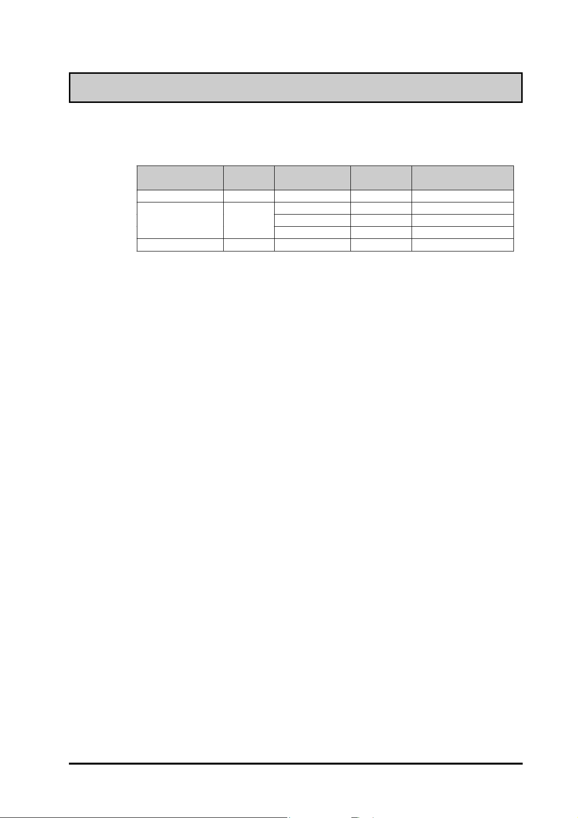
The FP's analog RGB interface offers normal display performance within the
following ranges:
VESA standard
display mode
VGA 640 x 480 31.5 kHz 60 Hz 25.175 MHz ± 0.4 %
XGA
US Text 720 x 400 31.5 kHz 70 Hz 28.300 MHz ± 0.4 %
Size
1024x 768 48.4 kHz 60 Hz 65.000 MHz ± 0.4 %
Horizontal
frequency
56.5 kHz 70 Hz 75.000 MHz ± 0.4 %
60.0 kHz 75 Hz 78.750 MHz ± 0.4 %
Vertical
frequency
Dot clock
frequency
Both the VGA and US Text mode displays can only use the "Centering" option.
Since some commercially-available video interface equipment also accomodates
tracking ranges in excess of those shown above, they may not offer normal display
performance when used with the PC. Before using a video interface, be sure to
check its specifications.
Also, even if the same type personal computer is used to transfer data to the PC,
the above mentioned problems can also occur when the PC's video board is
replaced.
The touch panel's PS/2 mouse connector can be used with equipment conforming
to PS/2 mouse standards, however specified performance cannot be guaranteed
with every PC and mouse combination.
Also, certain restrictions may apply to the touch panel's PS/2 mouse connector
depending on the OS being used.
If an extended mouse/keyboard cable is connected through the FP, the FP may not
operate normally , depending on the combination of the host and mouse/keyboard
or its cable length. In such a case, connect the mouse/keyboard cable directly to
the host.
While the FP('s OS) is starting up, please do not touch the screen's touch panel.
FP-775S User's Manual ix
Page 10

FP-775S Features
• Large-sized, high-quality color LCD
The monitor uses a 15 inch STN type color LCD, and its wide range of display
colors allow a wide variety of screen designs.
• FP's large-sized display is compatible with XGA mode
The FP is compatible with XGA mode, allowing a large variety of information to
be displayed.
• PC data can be displayed on the FP
Since the FP is connected to the host through an analog RGB interface, it can be
easily connected to a personal computer and used as a display.
Reference
• Panel-mount design allows the FP to be built into other equipment
The slim and compact body is designed specifically to be built into machine cabinets
and panels. Since the FP can be easily used with other equipment, it can be used as
a monitor for your PC-based FA or PA system. Also, the FP front panel's moisture
resistant gasket provides a dust and drip-resistant seal between the FP's front face
and the installation panel. Thus, the FP can be used even in harsh industrial
environments.
For the available display modes, see this chapter's “PC Connection
Notes”)
• Touch panel can be operated while PC data is monitored (Standard feature)
The FP's touch panel is standard equipment and is suitable for monitoring systems
that require touch operations. Also, the FP provides two types of interfaces between
the touch panel and the host: an RS-232C interface and PS/2 output via the mouse
port. These interfaces can be selected according to your system configuration needs.
x FP-775S User's Manual
Page 11
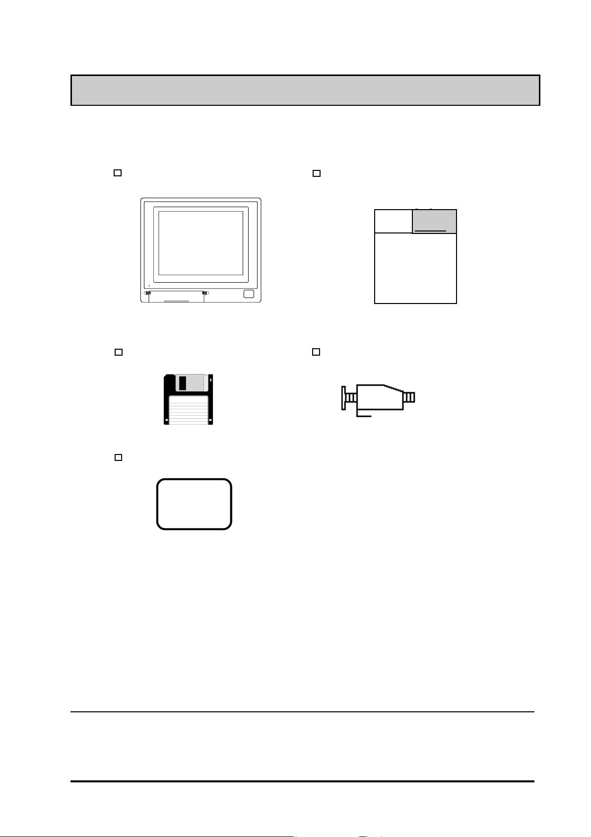
Package Contents
The FP's packing box contains the items listed below . Please check to be sure each is included
and is not damaged.
FP unit (FP775-S42)
3.5 inch floppy disk (1)
Moisture-resistant gasket (1)
Flat Panel Display FP-775S User's Manuals
(English and Japanese)
Digital
*1
Mounting brackets (12)
Pro-face
Pro-face
Flat Panel Display
FP775S
User’s Manual
These items have all been carefully packed with special attention to product quality .
However, should you find any item(s) damaged or missing, please contact your local
distributor immediately for prompt service.
*1 For description and usage of the application programs stored in the floppy disk, see
that disk's English “README” file.
FP-775S User's Manual xi
Page 12
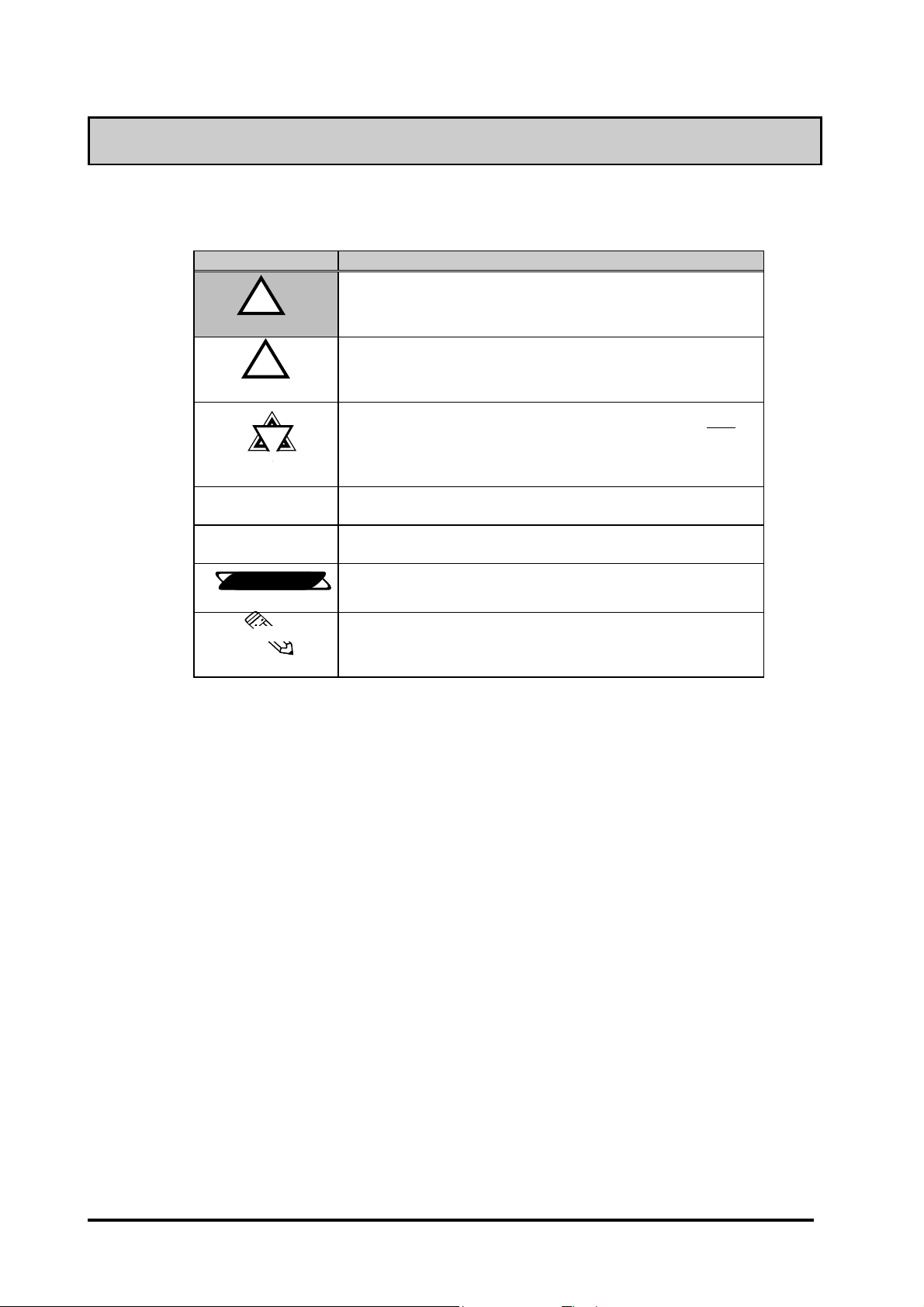
Symbol Information
The list below describes the symbols used in this manual.
Symbol Meaning
!!
!
!!
Warning
!!
!
!!
Caution
!!
!
!!
Important
*1
1) , 2)
Reference
Note:
Used to indicate situations where severe bodily injury, death or major
machine damage can occur.
Used to indicate situations where slight bodily injury or machine
damage can occur.
Used to indicate important information or procedures that must be
followed for correct and risk-free software/device operation.
Footnote marker used to provide useful or important supplemental
information.
Indicates steps in a procedure. Be sure to perform these steps in the
order given.
Used to refer to useful or important supplemental information.
Used to provide useful or important supplemental information.
xii FP-775S User's Manual
Page 13
Chapter 1
Introduction
1. Connecting the FP to a PC
2. Optional Equipment
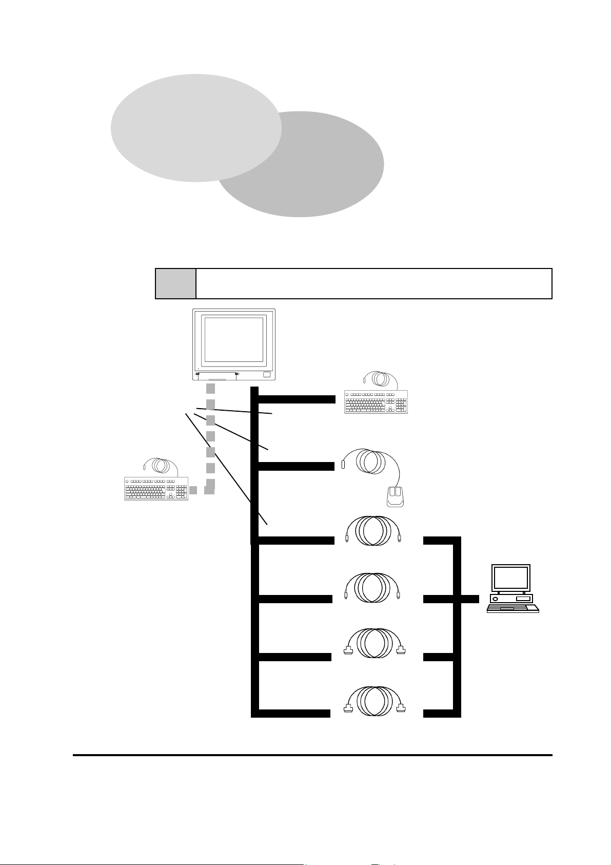
The following diagram illustrates the connection options available between the FP
and a PC.
1-1 Connecting the FP to a PC
FP Unit
(FP775-S42)
Reference No.s
*1
,
PS/2 compatible keyboard
(Commercially available type)
-
(
)
*
+
PS/2 compatible keyboard
(Commercially available type)
Microsoft Mouse
(Commercially available type)
Mouse/Keyboard cable
(Keyboard output) FP-CK01
Mouse/Keyboard cable
(Mouse output) FP-CK01
SIO cable (RS-232C)
FP61V-IS00-O
#
$
%
IBM PC
compatible
personal
computer
1* For a description of each reference no. used (', etc.) refer to the next page.
FP-775S User's Manual
'
RGB cable
(Analog RGB input) FP-CV00, FP-CV01
&
1-1
Page 14
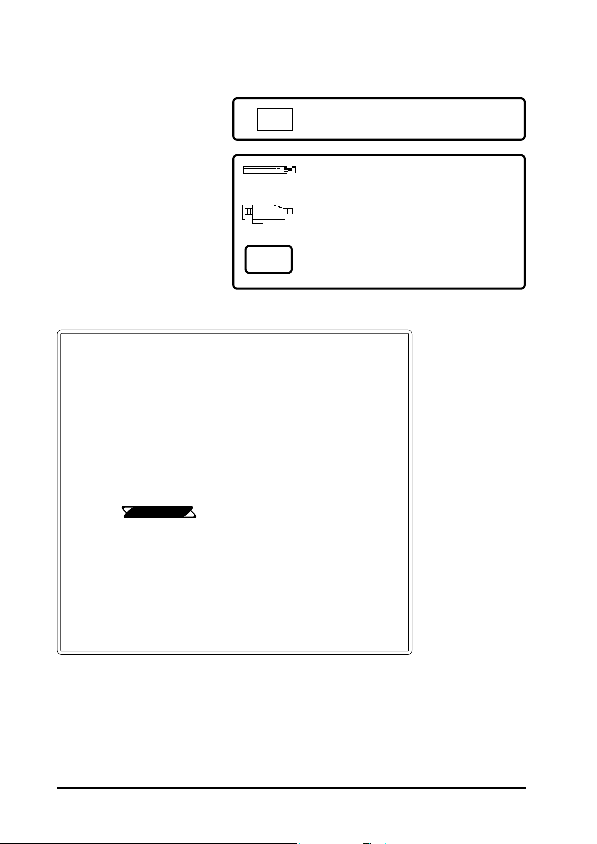
Optional Parts
(Sold separately)
Introduction
Display Protection Sheets (5 sheets/set)
FP77-COVER-5P
Maintenance Parts
These parts are included in
either the FP or its package as
standard equipment, and are
also optionally available for FP
maintenance.
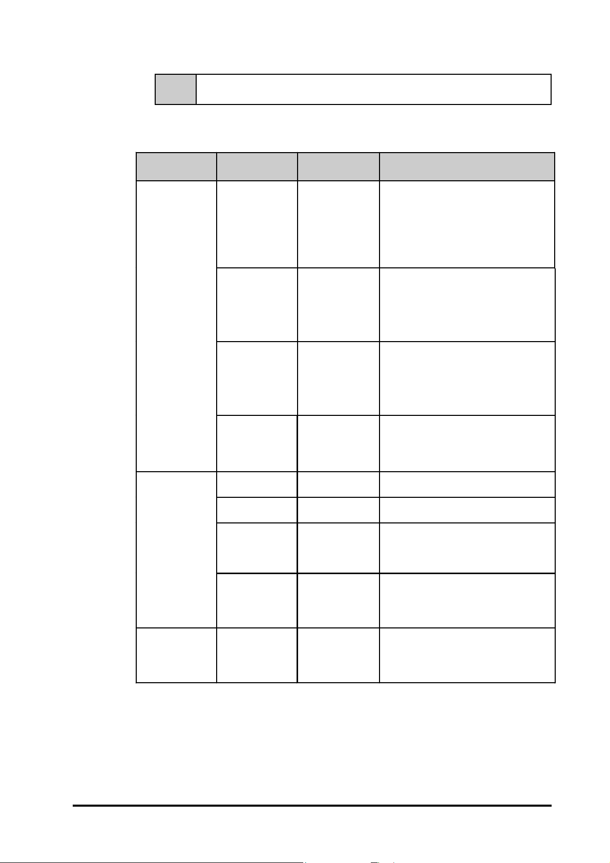
Page 1–1 Reference Number Description
FP Interface (inside front maintenance cover)
, KEYBOARD/Keyboard
FP Interface (rear face connectors)
- KEYBOARD/Keyboard
( MOUSE/Mouse
) KEYBOARD/PC
* MOUSE/PC
+ RS-232C connector
' Analog RGB I/F connector
Reference
Backlight (2 lights/set)
FP775S-BL00-MS
Mounting Brackets (4 brackets/set)
GP070-AT00-MS
Moisture-Resistant Gasket
FP77-WP00-MS
2-5 Names and Descriptions of FP Parts
Personal computer interface
# Keyboard interface
$ Mouse interface
% Serial interface
& Analog RGB interface
1-2 FP-775S User's Manual
Page 15
Introduction
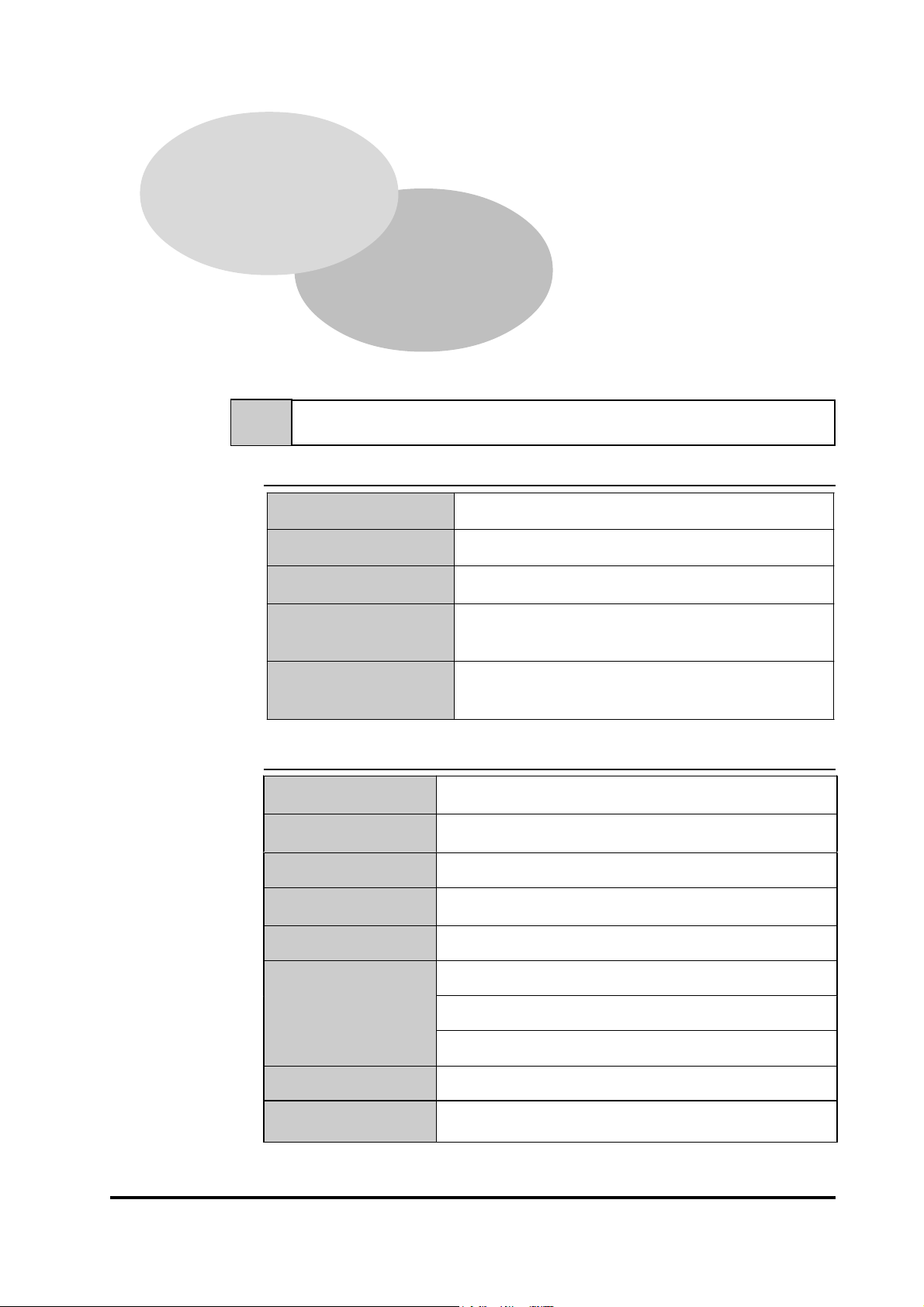
1-2 Optional Equipment
All items listed below are products of the Digital Electronics Corporation.
Item Name Model No. Description
Serial interface cable used for
transmission of touch panel data
between the FP and various hosts (PCs),
Interface
Cable
Types
SIO cable FP61V-IS00-O
RGB cable
RGB cable
FP-CV00
FP-CV01
and for the transmission of commands to
the FP. (5 m)
Compatible with PC/AT (D-sub 9-pin
female connector) computers
Analog RGB interface cable used to
output image signals from various host
(PCs) to the FP. (2.5 m)
Compatible with analog RGB interface (Dsub 15-pin male connector).
Analog RGB interface cable used to
output image signals from various host
(PCs) to the FP. (5 m)
Compatible with analog RGB interface (Dsub 15-pin male connector).
Maintenance
Parts
Optional
Parts
Mouse/Keyboard
cable
Backlight FP775S-BL00-MS
Mounting
brackets
Display Stand FP77-DS00
Moisture resistant
gasket
Display protection
sheets
FP-CK01
GP070-AT00-MS
FP77-WP00-MS
FP77-COVER-5P
Used to connect a mouse or keyboard
between the host and the FP. (2.5 m)
Compatible with PS-2 (mini DIN 4-pin/6pin male connectors) devices
Replacement Backlight Set
(2 lights/set - upper and lower lights)
Used to secure the FP to its installation
panel. (4 brackets/set)
Used to support the FP-775S. Provides a
nearly vertical viewing face and is
intended for maintenance or development
purposes only.
Used to prevent moisture from entering
the FP’s chassis. Same gasket as
originally included with the FP.
Disposable sheets that protect the display
from dust and dirt. The touch panel can be
used when one of these sheets is
attached. (5 sheets/set)
1-3FP-775S User's Manual
Page 16

MEMO
Introduction
1-4 FP-775S User's Manual
Page 17
Chapter 2
Specifications
1. General Specifications 4. Option Cable Pin Diagrams
2. Functional Specifications 5. Names and Descriptions of FP Parts
3. Interface Specifications 6. Flat Panel (FP) Dimensions
2-1 General Specifications
2-1-1 Electrical Specifications
Input Voltage AC 85 V to 265 V 50/60 Hz
Power Consumption Less than 65 VA
Allowable Power
Failure
Maximum Voltage
Isolation Resistance
AC 1500 V 20 mA 1 minute
(between the live wire and grounding
DC 500 V greater than 10 MΩΩΩΩ
(between the live wire and grounding
Within 20 ms
terminals)
terminals)
2-1-2 Environment Specifications
Operating
Temperature
Storage
Temperature
Ambient Humidity 30% RH to 85% RH (non-condensing)
Vibration
Resistance
Atmosphere Must be free of corrosive gas
Noise Immunity
(via noise simulator)
0 to 40 degrees Celsius
- 10 to 60 degrees Celsius
2 Gs at 10 to 25 Hz
(X, Y, Z directions: 30 minutes each)
Noise voltage : 1500 Vp-p
Pulse length : 50 ns/500 ns/ 1 µµµµs
Arise time (rise/fall): 1 ns
FP-775S User's Manual
Grounding
Rating
(with front panel closed)
*1 (See the next page's note)
*1
*2
Less than 100ΩΩΩΩ or your country’s applicable standard
Equivalent to IP65f (JEM1030)
2-1
Page 18

Specifications
(From previous page)
*1 For details, please contact your local FP distributor.
*2
The front face of the GP unit, installed in a solid panel, has been tested using conditions equivalent to the standard shown in the specification . Even though the GP unit’s
level of resistance is equivalent to the standard, oils that should have no effect on the
GP can possibly harm the unit. This can occur in areas where either vaporized oils are
present, or where low viscosity cutting oils are allowed to adhere to the unit for long
periods of time. If the GP’s front face protection sheet becomes peeled off, these
conditions can lead to the ingress of oil into the GP and separate protection measures
are suggested. Also, if non-approved oils are present, it may cause deformation or
corrosion of the front panel’s plastic cover. Therefore, prior to installing the GP be
sure to confirm the type of conditions that will be present in the GP’s operating environment.
If the installation gasket is used for a long period of time, or if the unit and its gasket
are removed from the panel, the original level of the protection cannot be guaranteed.
To maintain the original protection level, you need to replace the installation gasket
regularly.
2-1-3 Structural Specifications
External Dimensions
(mm)
Weight 7.5 kg or less (Unit only)
Cooling System Natural air circulation
(Unit only, including rear projections)
405 W x 350 H x 75 D
2-2 Functional Specifications
Display Media STN color LCD
No. of Display Colors 4096
Contrast Adjustment
Dot Pitch (mm) 0.297 W x 0.297 H
Touch Panel
Resolution
Possible via adjustment knob, located inside
of front face maintenance cover
1024 x 1024 (Max.)
2-2
Display Area (mm) 307 W x 231 H
Display Mode
(selected with a
switch)
Interfaces
Backlight
Analog RGB input, RS-232C input,
PS/2 input and output ( both mouse and
(under continuous 24 hour operation, lifetime
640 x 480 (VGA)
720 x 400 (US Text)
1024 x 768 (XGA)
keyboard)
CFL
= 17,000 hours)
FP-775S User's Manual
Page 19

Specifications
!!
!
!!
Important
2-3 Interface Specifications
Please use Digital's optional cable. If any other cable is used, due to
possible noise interference, Digiltal cannot guarantee the FP will
perform as specified.
2-3-1 Analog RGB Interface
Input signal type Analog RGB
Input signal
characteristics
Adjustment
features
Image signal : analog RGB
Synchronous signal : TTL level, negative true or positive true
Scanning type : non-interlaced
Flicker adjustment (DOT CLOCK)
Contrast adjustment
Horizontal display positioning
Vertical display p o sitioning
!!
!
!!
Important
VESA standard
display mode
VGA
XGA 48.4 kHz 60 Hz 65.000MHz ± 1 %
US Text
Size
640 × 480
1024
× 768
720 × 400
Horizontal
frequency
31.5 kHz 60 Hz 25.175MHz ± 1 %
56.5 kHz 70 Hz 75.000MHz ± 1 %
60.0 kHz 75 Hz 78.750MHz ± 1 %
31.5 kHz 70 Hz 28.300MHz ± 1 %
Vertical
frequency
Dot clock
frequency
The VGA and US Text modes can only use the centering display .
Pin Assignments and Signal Names for Analog RGB Connector
Pin
No.
1 Analog R R signal input
2
3 Analog B B signal input
4 Reserved NC (reserved for input)
5 Digital Ground Digital signal GND
6
7 Return G G signal GND
8 Return B B signal GND
9 Reserved NC (reserved for input)
10 Digital Ground Digital signal GND
11
12 Reserved NC (reserved for input)
13 H. SYNC
14 V. SYNC
15 Reserved NC (reserved for input)
Signal
Name
Analog G G signal input
Return R R signal GND
Reserved NC (reserved for input)
Condition Pin Location
Horizontal synchronous
signal input
Vertical synchronous
signal input
15
11
5
1
Connector : Mini Dsub 15 pin male
Connector set screw : Inch type (4-40)
Cable : Digital Electronic Corporation RGB cable
FP-775S User's Manual
(FP-CV00, FP-CV01)
2-3
Page 20

Specifications
2-3-2 Serial Interface
Baud rate : 9600 bps
Serial Interface
Pin Assignments and Signal Names for Serial Interface Connector
Data length : 8 bits
Parity : None
Stop bit : 1
Pin
No.
Signal
Name
1 CD Carrier Detect (FP –> Host)
2
3 SD Send Data (FP <– Host)
4 DTR Data Terminal Ready (FP <– Host)
5 GND Ground
6
7 RS Request to Send (FP <– Host)
8 CS Clear to Send (FP –> Host)
9 NC No connection
RD Receive Data (FP –> Host)
DSR Data Set Ready (FP –> Host)
Condition Pin Location
6
9
1
5
Connector : Dsub 9 pin female
Connector set screw :Inch type (4-40)
Cable : Digital Electronic Corporation SI0 cable (FP61V-IS00-O)
Signal Names
Signal names used for the FP's serial interface are designed to match the pin
order used on most PC serial interfaces, so that a straight cable can be used to
connect the two. Therefore, connect each pin's signal to the same signal name
on the PC connector .
For example, pin #2 'RD' should be connected to the PC's 'RD' pin (terminal).
Refer to section "2-4 Option Cable Pin Diagrams" for information about each
signal's direction.
2-4
FP-775S User's Manual
Page 21

Specifications
2-3-3 Keyboard Interface (KEYBOARD - Keyboard)
Mini DIN 6-pin (Female)
6
4
2
<Manufactured by Hoshi Electronics,Inc.:
TCS7568-43-201 or equivalent>
Possible keyboards:
1
FKB1424-001 (compact type) manufactured by Fujitsu,Inc.
FKB4874-101 manufactured by Fujitsu,Inc.
5
3
2-3-4 Mouse Interface (MOUSE - Mouse)
Mini DIN 6-pin (Female)
6
5
(Common to front and rear)
Pin
No.
1
2
3
Signal name
KEY DATA
NC
GND
4 +5V
5
6
Pin
No.
1
2
KEY CLK
NC
Signal name
MOUSE DATA
NC
3
4
3
4 +5V
5
2
<Manufactured by Hoshi Electronics,Inc.:
TCS7568-43-201 or equivalent>
1
6
Suggested Mouse: Microsoft (Corp.)'s Microsoft mouse (PS/2 type)
2-3-5 PC Interface (MOUSE-PC/KEYBOARD-PC)
Mini DIN 4-pin (Female)
Pin
4
2
3
No.
1
2
3
1
4 DATA
GND
MOUSE CLK
NC
Signal name
GND
+ 5V
CLK
<Connector Maker: JST , MD-S6100 or equivalent>
FP-775S User's Manual
2-5
Page 22

Specifications
2-4 Option Cable Pin Diagrams
RGB Interface Cable Pin (Optional cable: VGA specification) Assignments
FP Connector
1 Analog R Input
2 Analog G Input
3 Analog B Input
4 Reserved –
5 Digital ground –
6 Return R –
7 Return G –
8 Return B –
9 Reserved –
10 Digital ground –
11 Reserved –
12 Reserved –
13 H.SYNC Input
14 V.SYNC Input
15 Reserved –
FG FG –
1 RED IN
2 GRN IN
3 BLU IN
4 NC
5 GND
6 RED GND
7 GRN GND
8 BLU GND
9 NC
10 GND
11 NC
12 NC
13 HSYN
14 VSYN
15 NC
FG FG
RGB cable
RED VIDEO 1
GRN VIDEO 2
BLU VIDEO 3
GROUND 5
GROUND RED 6
GROUND GRN 7
GROUND BLU 8
GROUND 10
MONITOR
SENSE(COLOR)
MONITOR
SENSE(MONO)
HSYN 13
VSYN 14
NC 4
NC 9
11
12
NC 15
FG FG
PC Connector
Output RED VIDEO 1
Output GRN VIDEO 2
Output BLU VIDEO 3
– NC 4
– GROUND 5
–
–
–
– NC 9
– GROUND 10
–
–
Output HSYN 13
Output VSYN 14
– NC 15
GROUND RED
GROUND GRN
GROUND BLU
MONITOR
SENSE(COLOR)
MONITOR
SENSE (MONO)
11
12
6
7
8
• Signal names for the FP's RGB interface are designed to match the same pin order
as the RGB interface on standard PCs. Since this cable (FP-CV00, FP-CV01)
is designed to use the same pin numbers for the FP and the PC, it can be connected
in either direction.
• Since the PC connector's pitch is designated in “inch” units, the interface cable and
the FP connector's pitch are also designated in “inch” units (4-40).
2-6
FP-775S User's Manual
Page 23

Specifications
Pin Connections for the SIO Interface Cable (Optional cable: PC/A T specification)
FP Connector
1 CD Output
2 RD Output
3 SD Input
4 DTR Input
5 GND -6 DSR Output
7 RS Input
8 CS Output
9 NC --
FG FG --
1 CD
2 RD
3 SD
4 DTR
5 GND
6 DSR
7 RS
8 CS
9 NC
FG FG
SIO cable
CD 1
RD 2
SD 3
DTR 4
GND 5
DSR 6
RS 7
CS 8
NC
RI 9
FG 9
FG
PC Connector
Input CD 1
Input RD 2
Output SD 3
Output DTR 4
-- GND 5
Input DSR 6
Output RS 7
Input CS 8
Input RI 9
Signal names for the FP's SIO interface are designed to match the same pin order as
the SIO interface on standard PCs. As a result, the FP61V-IS00-O can be connected
in either direction.
Since the PC connector's pitch is designated in “inch” units, the interface cable and the
FP connector's pitch are also designated in “inch” (4-40) units.
Mouse/Keyboard Cable Pin Numbers
Mouse/Keyboard cable
PC Connector
FP Connector
1GND 2 +5V 3CLK In/Out
4 DATA In/Out
1GND
2+5V
3CLK
4DATA
(WHITE)
DATA 1
NC 2
GND 3
+5V 4
CLK 5
NC 6
(BLACK)
In/Out DATA 1
-NC2
-GND3
-+5V4
In/Out CLK 5
-NC6
The signal names of the FP unit interface and the mouse/keyboard cable (FPCK01) conform to those of the personal computer interface. T o prevent accidents
and connector damage, please be aware that the ends of this connector are
different. Connect the 4 pin (white) connector to the FP, and the 6 pin (black)
connector to the PC.
FP-775S User's Manual
2-7
Page 24

2-5 Names and Descriptions of FP Parts
Front View
A: STN type color LCD
The FP units’ output display . Data from
the host are displayed.
B: T ouch panel
Used to switch screens and write data into
the host.
C: Power input terminal block
Used to connect the power supply cable.
D: Setting switches (DIP switches)
K
Rear View
A,B
Used to set the FP's operation mode.
E: Analog RGB I/F connector
Analog RGB interface connector
F: RS-232C connector
RS-232C (serial) interface connector used
to send touch panel data between the FP and
host, and to send commands to the FP .
Specifications
C
FE D
Bottom View
CF
JIHG
G: MOUSE/Mouse connector
Accepts standard mouse input.
H: MOUSE/PC connector
Used to output mouse data from the FP
(to a PC). Cable from here connects to any
PS/2 compatible mouse input connector .
I: KEYBOARD/Keyboard connector
Used to connect the PS/2 compatible
keyboard.
J: KEYBOARD/PC connector
E
D
Used for FP keyboard data output.
Connects to the PS/2 compatible
keyboard input connector.
K: Front maintenance cover
Protects the FP's RESET switch, keyboard
connector and contrast adjustment knob.
2-8
!!
!
!!
Important
Be sure that all cables are connected correctly and that the FP is
turned OFF before any cables are disconnected, since either of these
can cause the FP to malfunction.
FP-775S User's Manual
Page 25

Specifications
2-6 Flat Panel (FP) Dimensions
2-6-1 FP-775S External Dimensions
Unit:mm
Note:
350
For detailed dimension information, please contact your local FP distributor.
Top View
8
Front View
405
202.5
8
Side View
75
8
236
195
Rear View
4
8
13.2
45
FP-775S User's Manual
2-9
Page 26

2-6-2 Installation Brackets
Specifications
Unit: mm
∅10
Front View
Top View Rear View
27
19.5
M5
16
8
Side View
5
4.6
2-6-3 FP Installation Hole Dimensions
Unit: mm
+0.5
0
335
390
Panel
+0.5
0
11
1.6
less than 4-R2
3
2-10
!!
!
!!
Important
If the FP's mounting panel is not sufficiently thick or strong,
the specified level of moisture-resistance may not be possible.
FP-775S User's Manual
Page 27

Installation and Wiring
Chapter 3
Installation and Wiring
1. Installation
2. Wiring
3. Setup of Operation Mode and Positioning of Display
3-1 Installation
3-1-1 Installation Procedures
!!
!
!!
Important
Note:
• Before installing the FP, be sure the moisture-resistant gasket is
securely attached.
Rear
Face
■■
■ Create an Installation Hole
■■
Using these FP installation dimensions as a guide, create (cut) the correct sized
installation opening. The FP's seal, installation brackets and screws are all required
when installing the FP . 2-6-3 FP Installation Hole Dimensions
Installation
Hole
• It is important that the plate/panel surface is flat, clean, and without any
jagged edges. If the panel is thin and may warp, attach a reinforcing plate to
the panel.
• The Plate/Panel thickness should be between 1.6 and 10.0mm.
Reference
Installation Plate/Panel
Gasket
!!
!
!!
Important
FP-775S User's Manual
• If the plate/panel used is too thin or weak, a satisfactory moisture-
1.6 to 10mm
FP
resistant seal may not be created.
3-1
Page 28

Note:
Installation and Wiring
• For easier maintenance and operation, and improved ventilation, be
sure the FP is installed at least 100 mm away from any adjacent
structures or objects.
100mm
100mm
100mm
100mm 100mm
100mm
100mm
• The FP uses natural ventilation through its outer shell for cooling.
When installing the unit horizontally or sideways (portrait style),
use a fan or air conditioning unit to prevent overheating.
Horizontal Installation
(Landscape type)
Side
V iew
Front
View
• Check that heat from surrounding equipment will not cause the FP to overheat.
• The FP should not be used in areas where the ambient temperature will exceed
40 degrees centigrade.
• Be sure this unit is located as far away as possible from electromagnetic circuits, non-fuse type breakers, and other equipment that can cause arcing.
• When installing the FP in a panel with an angled face, the face should not
o
incline either backwards or forwards more than 30
.
less than 30
Insert the FP into the installation hole from the front of the panel.
o
Panel
Side
view
3-2
FP-775S User's Manual
Page 29

Installation and Wiring
■■
■ Secure the FP in place using the mounting brackets.
■■
Insert the mounting bracket hooks into the slots provided on the top, bottom
and sides of the FP (three slots on the top and bottom and three slots in the
right and left sides, respectively).
1)
Top View
Bottom
View
2)
Mounting Bracket
Hook
Bracket slot
Panel
Front
Rear
Bracket
slot
3)After inserting the hook into the slot, move the bracket backward. Then, use
a screwdriver to tighten the screw and secure the FP in place.
4) Tighten the mounting bracket's screw with a screwdriver. To ensure the FP's
front panel is sufficiently moisture-resistant, tighten the screw with no more
than 0.5 to 0.6 N•m of torque.
!!
!
!!
Important
Excessive torque may cause damage to the unit.
FP-775S User's Manual
Panel
FP
3-3
Page 30

Installation and Wiring
3-2 Wiring
This section describes wiring installation precautions and the FP's power cable
wiring procedures.
3-2-1 Power Cable Connection Precautions
!!
!
!!
Warning
!!
!
!!
Important
Note:
• When connecting the power cable, be sure that power
is not supplied to the FP due to the danger of electric
shock.
• If a voltage exceeding the FP's specified power range
is applied, both the FP and the power supply units
will be damaged.
• Since the FP has no power switch, be sure to set up a
separate circuit breaker.
• When the frame ground (FG) terminal is not connected, the FP is
easily affected by noise interference. Be sure to ground the unit.
• Use thick wire (2 mm
ends are twisted before attaching the ring terminals.
• Use ring terminals with the following dimensions:
less than 6.0 mm
2
max.) for the FP's power cord. Be sure that the cord wire
3.2 mm
• To prevent the power terminals from being short-circuited due to a loose screw,
use ring terminals with insulating sleeves.
Rear of FP
Power Input Terminal Block
LNFG
LNFG
LN FG
*1 L = Live line for AC power input
N = Neutral line for AC power input
FG = Ground terminal - to be connected to the FP housing
Recommended ring terminal: V2-MS3 or equivalent (Manufactured by JST Co.)
Power Cord Ring Terminals
*1
3-4
FP-775S User's Manual
Page 31

Installation and Wiring
3-2-2 FP Power Cable Connection Procedure
1) Check to make sure the FP's power cord is disconnected from the main
power supply.
2) Remove the terminal block's transparent cover.
3) Remove the screws from the 3 middle terminals, align the ring terminals
and re-attach the screws. (Check that each wire is securely connected)
4) Replace the terminal block's transparent plastic cover.
Note:
Use no more than 0.5~0.6N•m of torque to tighten the screws.
FP-775S User's Manual
3-5
Page 32

3-2-3 FP Power Supply Connection Procedures
Please pay special attention to the following points when connecting the
power cord to the FP-775S's Power Input Terminal Block.
Fig. 1 - Connecting a Voltage Transformer
constant
voltage
transformer
Twisted
Lines
FP
If the voltage supplied exceeds the FP's
designated range, connect a voltage transformer.
Reference
tions", for the allowable voltage range.
Fig. 2 - Connecting an Insulating Transformer
Installation and Wiring
Chapter 2, "Specifica-
Twisted
insulating
transformer
Lines
FP
Note:
Fig.s 3 & 4 - Separating Signal LInes
main
power
main
power
FP
power
power
input/output
FP
power
FP
input/output
unit
FP
Between the line and ground, select a power
supply that is low in noise. If there is an
excessive amount of noise, connect an
insulating (noise reducing) transformer.
Use V oltage and Noise Reducing transformers with capacities in excess of 100VA.
When supplying power to the FP, separate
the power input/output and operation signal
lines as shown in figure 3.
To increase the FP's noise resistance, twist
the power cord's wire ends before connecting them to the FP.
The power cord must not be bundled or kept
close to the main circuit lines (high voltage,
high current), or input/output signal lines.
3-6
power
input/output
main circuit
Input/ Output Unit
Input/ Output Unit
Operation
Unit
FP-775S User's Manual
Page 33

Installation and Wiring
Fig. 5 - Connecting a Surge Absorber
FP
Connect a surge absorber, as shown in the diagram,
to deal with power surges.
To prevent noise, make the power cord as short as
surge
absorber
Note:
possible.
Be sure the surge absorber (E1) is grounded separately
from the FP (E2).
Select a surge absorber that has a maximum circuit
voltage greater than the power supply's peak voltage.
3-2-4 FP Grounding Cautions
Exclusive Grounding (BEST)
Nearby
FP
equipment
*1
Connect the FP's FG terminal to an exclusive ground.
Common Grounding (OK)
*1
If exclusive grounding is not possible, use
a common grounding point.
FP
Nearby
equipment
Make the connection point as close to the
FP as possible, and make the wire as short
as possible. When using a long grounding
wire, use a thicker wire placed in a duct.
If the FP does not function properly when
grounded this way , disconnect the ground
wire from the FP's FG terminal.
Common grounding (BAD)
FP
other
equipment
3-2-5 FP Input/Output Signal Line Cautions
Input and output signal lines must be separated from power cables.
*1 Use a grounding resistance of less than 100Ω and a 2mm
country's applicable standard. For details, contact your local FP distributor .
FP-775S User's Manual
If this is not possible, use a shielded cable and connect the shield to the
FP chassis.
2
or greater thickness wire, or your
3-7
Page 34

Installation and Wiring
3-3
Setup of Operation Mode and Positioning of Display
3-3-1 Operation Mode Setup and Adjustment
The setup switches (dip-switches) are located in the rear of the FP.
FP-775S (rear view)
DIP-switch (SW-1)
Prior to shipment, the FP's DIP switches (collectively called SW1) have been
set as shown above. These 8 DIP switches control the items listed below:
No. Function OFF ON
1 Touch Panel Output Method
2 Backlight Setting 1
3 Backlight Setting 2
Backlight Setting 3
4
5 Calibration Normal mode Calibration mode
6 Click Sound Click sound OFF Click sound ON
7 Reserved Set this switch to OFF
8 Reserved Set this switch to OFF
RS-232C output PS/2 mouse compatible
output
See table on next page
• SW1-1
Designates the touch panel data output method.
OFF: SIO (RS-232C) output
When the FP is connected to the host (PC), emulation software
(e.g TT-WIN) is required to perform touch operation.
ON: PS/2 mouse compatible output
Touch panel data is converted to PS/2 mouse-compatible format,
and output through the mouse output port.
When the FP is connected to the Host's PS/2 mouse port, you can
perform touch operation without using special emulation software
or a special driver.
3-8
!!
!
!!
Important
• The use of PS/2 mouse compatible output may be limited, depending
on the OS being used.
Reference
4-2 Touch Panel Data Input
FP-775S User's Manual
Page 35

Installation and Wiring
• SW1-2, SW1-3, and SW1-4
These switches are used in various combinations to control the backlight
brightness used at start-up, automatic dimming, and automatic switch-off of the
backlight after 2.5 and 5 minute intervals of no SIO communication or touch
panel operation.
Once SIO communication or touch operation is performed, the backlight is
returned to its initial condition.
SW1-2 SW1-3 SW1-4
!!
!
!!
Important
After 2.5
minutes without
Brightness at
start-up
OFF OFF OFF Low brightness
ON OFF OFF High brightness
OFF ON OFF Low brightness OFF
ON ON OFF High brightness OFF
OFF OFF ON Disabled
ON OFF ON High brightness Low brightness
OFF ON ON Disabled
ON ON ON High brightness Low brightness OFF
SIO
communication
or touch
operation
After 5 minutes
without SIO
communication
or touch
operation
• When the FP receives a display-related SIO command from the host,
the backlight’s automatic brightness reduction/power-off functions
are canceled.
• T o perform simultaneous keyboard and touch panel operation, do
not enable the backlight’s automatic dimming/switch-off functions,
since during keyboard operation these functions cannot be reactivated.
• SW1-5
This switch is used to enable recalibration of the PS/2 mouse compatible
output mode (when the SW 1-1 is ON). This feature allows the User to correct
any displacement that way have developed between the screen's displayed
position and the actual touch position.
Use the following steps to recalibrate the screen:
1) Set the SW1-5 switch to ON to start the recalibration mode. (The FP's
buzzer sounds, and touch panel data output is halted)
2) Press the upper right corner of the display. (A)
3) Press the lower left corner of the display.(B)
In calibration mode, removing your finger
Note:
from the screen will enable that position and
cause a short beep to sound.
When the input is incorrect (due to the
procedures being performed out of order,
etc.) a warning beep will sound and the unit
will wait for the correct input.
(B)
(A)
4) Set the SW1-5 switch to OFF to quit the recalibration mode. (The FP
stores the calibration data, sounds the buzzer, and re-starts touch panel
data output)
The buzzer will sound continuously while the calibration data is
!!
!
!!
Important
being saved. While the buzzer is sounding, do not reset the unit or
turn it OFF.
FP-775S User's Manual
3-9
Page 36

Installation and Wiring
• SW1-6
This switch is used to set the FP touch panel's click sound.
When set to ON, every time the touch panel is touched in the PS/2 mouse
compatible output mode (when SW 1-1 is ON), a click will sound.
• SW1-7
This switch is reserved for future system expansion.
Set this switch to OFF.
• SW1-8
This switch is reserved for future system expansion.
Set this switch to OFF.
3-3-2 Touch Panel Display Adjustment
Press both the RESET switch located in the front maintenance panel and the
upper left corner of the FP display to start display adjustment mode.
In display adjustment mode, specified areas on the touch panel are used as setting
switches (see the figure below). These switches can be used to adjust the dot
clock phase/frequency and display position. (The following figure is a schematic
view only for explanation. An actual screen will show host output data)
UP
Press this
position to reset
the FP.
LEFT
DOT CLOCK
_
DOWN
DOT CLOCK +
PHASE
RIGHT
DOT CLOCK + Adjusts the dot frequency up to compensate for flicker.
DOT CLOCK
_
Adjusts dot frequency down to compensate for flicker.
UP/DOWN UP Adjusts the display's position up.
3-10
DOWN Adjusts the display's position down.
RIGHT/LEFT RIGHT Adjusts the display's position to the right.
LEFT Adjusts the display's position to the left.
PHASE Adjusts the dot clock phase.
FP-775S User's Manual
Page 37

Installation and Wiring
To perform display adjustments, use the following procedures:
1) Press the RESET switch located in the front maintenance panel while touching
the upper left corner of the FP display to start the display adjustment mode.
2) Use the setting switches to change the value of the selected item.
3) Press the upper left corner of the FP display again to exit the display
adjustment mode.
!!
!
!!
Important
When adjustment data is being saved, the FP's buzzer will sound. Be
sure to wait until the buzzer is silent before turning the FP OFF.
3-3-3 Contrast Adjustment
The FP's contrast can be adjusted via the volume adjustment slide, located inside
the Front Maintenance Cover. Simply move this slide until the desired level of
contrast is achieved.
Contrast Volume
Adjustment Slide
3-3-4 Color/Hue Adjustment
When the FP's color is incorrect or requires special adjustment, the color/hue level
can be adjusted via the Color/Hue Adjustment Opening. Use a small, thin screwdriver
to turn the knob located inside this hole, until the desired color is achieved.
!!
!
!!
Important
Note:
FP-775S User's Manual
Be sure to use a small ceramic or plastic type screwdriver to prevent
static electricity from harming any of the FP's components, or causing
a malfunction.
Color/Hue flicker may be caused by the use of half-tone colors. To prevent this, try
to always use only the FP's standard colors.
Color/Hue
Adjustment Opening
3-11
Page 38

MEMO
Installation and Wiring
3-12
FP-775S User's Manual
Page 39

Chapter 4
Touch Panel Commands
1. Serial Command List 3. Boot-up Initialization/Reset
2. Touch Panel Data Input
4-1 Serial Command List
This section describes the serial commands available with the FP (command
transmission from the host (PC) to the touch panel (FP)).
<Serial Command List>
Code Function
65h
66h
67h
69h
6Ah
71h
72h
73h
74h
75h
76h
Turns on the backlight at high brightness.
Turns on the backlight at low brightness.
Turns off the backlight. (Automatic reset)
Turns on the click sound.
Turns off the click sound.
Turns on the buzzer.
Turns off the buzzer.
Turns on calibration mode.
Turns off calibration mode.
Turns on touch panel data output.
Turns off touch panel data output.
• All codes other than those shown here are reserved. These
!!
!
!!
Important
Note:
Backlight ON (High brightness) 65h
Turns on the backlight at high brightness.
Backlight ON (Low brightness) 66h
Turns on the backlight at low brightness.
FP-775S User's Manual 4-1
commands should never be issued when using the FP.
• All data and command codes are expressed in hexadecimal
numbers. (Example: 65h = 65HEX)
Page 40

Touch Panel Commands
Backlight OFF (Automatic reset) 67h
Turns off the backlight. When either SIO communication or touch
operation is performed, the backlight is turned on.
• The backlight condition after reset depends on the DIP switch
Note:
Click sound ON 69h
Every time you touch the display panel a click will sound.
Click sound OFF 6A h
Turns off the click sound.
Buzzer ON 71h
Turns on the buzzer output
Buzzer OFF 72h
Turns off the buzzer output.
settings (SW1-2, SW1-3, and SW1-4).
Note:
• Priority is given to buzzer output over the click sound. Thus, when
both the buzzer output and click sound are set to ON, the buzzer
output is activated.
Buzzer Click Status
ON ON Buzzer ON
ON OFF Buzzer ON
OFF ON Click sound ON
OFF OFF Buzzer and click sound OFF
Calibration mode ON 73h
Starts touch panel calibration mode. (Same function as when SW1-5 is
ON.)
Calibration mode OFF 74h
Ends touch panel calibration mode. (Same function as when SW1-5 is
OFF.)
Touch data ON 75h
Enables touch panel data output.
Touch data OFF 76h
Disables touch panel data output.
4-2 FP-775S User's Manual
Page 41

Touch Panel Commands
4-2 Touch Panel Data Input
T wo connection methods are available for sending touch panel data from the FP
to the host: an RS-232C connection and a PS/2 mouse compatible connection.
This section includes instructions for creating both.
RS-232C connection (When SW1-1 is OFF)
When the touch panel is used during the RS-232C (SIO) connection mode,
coordinate output data sent from the FP to the host is not exactly equal to the
coordinates used on the display device. Therefore, an I/F program is necessary
to convert the coordinates on the touch panel into those used on the display
device. It is also necessary to calibrate individual differences, depending on the
touch panel used.
The mouse emulation software listed below can automatically convert the
coordinates with simple initial settings.
*1
SW1-1
setting
OFF
(RS-232C
output)
OS I/F program Calibration Application
Windows® 95
WindowsNTTM4.0 TT-WIN/NT*1
Windows® 3.1 TT-WIN*1
Other OS Prepared by user
PL-ME000*1
Included in I/F
program
Included in I/F
program
Included in I/F
program
i.e. FIX-DMACS
Depending on
the specifications of
the program
i.e. FIX-32
i.e. FIX-32
*1
*1
A separate conversion program is required for a different user-prepared OS. To
create a conversion program for a different OS, please observe the following
instructions:
(1) Resolution
The FP has “1024” resolution in both the X and Y axes. The origin point (0,0) is
in the upper right corner.
(0,0)
The display device however provides “1024 x
768” resolution with the origin point located in
its upper left corner. Therefore, the FP's touch
panel data must be converted to the actual
display coordinates.
(1023,1023)
*1 The following software programs are sold separately:
PL-ME000: Mouse simulation software for Windows 95, manufactured by the Digital
Electronics Corporation
TT-WIN: PC/AT-compatible mouse simulation software for Windows 3.1,
manufactured by GUNZE LIMITED
TT-WIN/NT: PC/AT-compatible mouse simulation software for Windows NT,
manufactured by GUNZE LIMITED
FIX-DMACS: Personal computer instrumentation package software, manufactured by
INTELLUTION
FIX-32: Personal computer instrumentation package software, manufactured by
INTELLUTION
4-3FP-775S User's Manual
Page 42

Touch Panel Commands
(2) Data Format
All data is in 8-bit ASCII format, and is structured in the following 11 byte
strings.
Header: 1 byte (T = touched; R = released)
X coordinate: 4 bytes (0000 ~ 1023)
Separator: 1 byte (,)
Y coordinate: 4 bytes (0000 ~ 1023)
Termination code: 1 byte (CR = 0Dh)
X coordinate Y coordinate
31h ('0') ~ 39h ('9')
four digits
31h ('0') ~ 39h ('9')
four digits
54h ('T') : T ouched
52h ('R') : Released
<Example>If the coordinate (X=23, Y=500) is touched.
2Ch (',') : fixed 0Dh ('\n') : fixed
T0023, 0500CR touched
T0023, 0500CR continuous output at the same location
T0024, 0500CR moving the finger without releasing touch
T0024, 0499CR
continuous data output unless finger is released
T0022, 0501CR
T0023, 0500CR
R0023, 0500CR when released, only 1 unit of data is sent
(3) Sampling Rate
A maximum of 87 points per second.
• The PL's touch panel provides a resolution of “1024” (10
!!
!
!!
Important
bit). However, the resolution of the actual output data is
only 20 to 990 (approx.). Therefore, the coordinates of the
horizontal axis pixels cannot be detected.
(4) Cable Connection
Connect the RS-232C connector provided at the rear of the FP to the host’s
serial interface through the optional SIO cable.
Reference
Chapter 1 Introduction
4-4 FP-775S User's Manual
Page 43

Touch Panel Commands
Connecting a PS/2 mouse (When SW1-1 switch is ON)
When the FP's PS/2 mouse connection mode is selected and the User's OS
supports the PS/2 mouse, touch panel data is converted to PS/2 mouse data, and
output through the MOUSE/PC connector. In this case, the I/F program that
converts the coordinates output from the FP to the host (PC) into the display device
coordinates is not necessary .
(1) Setting up the mouse according to the current OS
Turn the FP and host (PC)'s power on, and set up your OS's mouse and driver
settings so that the PS/2 mouse can be used.
Note:
• For information about the mouse's setup procedure, refer to your
OS maker's Operation manual.
(2) Connecting the data cable
Connect the optional mouse/keyboard cable to the MOUSE/PC connector
provided at the rear of the FP and to the host (PC)'s mouse connector port.
Reference
Chapter 1 Introduction
(3) Connecting the mouse
The FP's touch panel can be used together with a mouse. Connect the
mouse to the MOUSE/Mouse connector at the rear of the FP.
• After connecting the mouse, re-start the FP's OS.
Note:
• When Windows 95 or Windows NT is used, set the “Control panel
- Mouse - Operation” feature to
the pointer trace.
the slowest pointer speed and hide
• Do not connect this cable when the power to the FP
!!
!
!!
Important
and the host (PC) are both ON.
• When a mouse is connected to the FP , it may not operate
normally, depending on the combination of host (PC)
and mouse used, as well as the cable length.
• The mouse connection can be used for all equipment
conforming to the PS/2 mouse standards. However,
Digital cannot guarantee the FP will operate normally
for all types of host and mouse combinations. This unit
was developed using the Microsoft Mouse®. Microsoft's
other mouse products, the "IntelliMouse" and the "3
Button" mouse may not be used with this unit.
4-5FP-775S User's Manual
Page 44

Touch Panel Commands
Conditions and restrictions : Connecting a PS/2 mouse
The following conditions and restrictions apply when a PS/2 type mouse is
used with the FP-775S. Due to the effect of the combination of the type of PC,
mouse and OS used, the FP-775S's touch panel may not operate correctly .
(1) Please be sure that the mouse driver used is the "Microsoft PS/2 Port Mouse".
In the Windows 95/NT "Control Panel" settings area, double-click on the Mouse
icon to bring up the Mouse settings. First, click on the "Motion" tab, then drag
the "Pointer Speed" setting bar to the far left for the fastest movement. Next,
be sure the "Pointer Trail" "Show Pointer T rail" checkbox is not checked.
(2) The "double-click" feature should be used only for maintenance or when
developing applications, due to mouse operability problems that may occur.
(3) The following PC's may have some coordinate positioning errors.
• When the FP-775S is connected to a PC running the Windows NT OS, if the
video controller used is the S3 TRIO64 V iRGE, the touch position may be
slightly skewed.
This phenomenon has been confirmed on the IBM-PC350 and the Fujitsu
FMV-620T6C7 personal computers.
• When using a laptop-type PC, or PC that utilizes both mouse and nonmouse pointing devices, or a PC that accepts "Hot Swappable" type devices,
the touch position may be slightly skewed.
This phenomenon has been confirmed on the T oshiba Dynabook 440CDT ,
and the SONY VAIO laptop PCs.
(4) This unit is not compatible with OS/2 PCs and devices.
Since OS/2 PCs and devices use the function is not compatible, it cannot
use in this unit.
When using the FP-775S in your system, be sure to test the unit carefully with all the
connected devices.
4-6 FP-775S User's Manual
Page 45

Touch Panel Commands
4-3 Boot-up Initialization/Reset
When the power is turned ON, the touch panel is initialized as follows.
• Clears its internal buffer .
• Initializes the serial communication mode.
Baud rate 9600bps
Data length
Parity None
Stop bit 1 bit
• Initializes the system default values.
Function Default setting
Backlight ON
Backlight condition Depending on the SW1-2,3,4 settings
Click sound Depending on the SW1-6 setting
Buzzer OFF
Calibration mode OFF
Touch panel data output
8 bits
ON
4-7FP-775S User's Manual
Page 46

MEMO
Touch Panel Commands
4-8 FP-775S User's Manual
Page 47

Chapter 5
Troubleshooting
1. Troubleshooting
5-1 Troubleshooting
5-1-1 Possible Device Problems
T wo possible types of trouble are as follows.
• No display
- No display appears after the unit is switched on.
- The screen disappears during RUN mode.
- The screen display is not normal.
• Touch Panel Does Not Respond
The touch panel does not respond when pressed, or its response time is abnormally
slow .
Troubleshooting procedures for these problems are described in the flowcharts on the
following pages.
Warning
• Because of the danger of an electric shock, be sure the
power cable is not connected when wiring the unit.
• When changing the backlight, since there is a danger
of an electric shock or burn, be sure to turn the FP
off and wear gloves.
This section assumes that the FP is the cause of a problem,
not the host (PC). When the host is the problem, please
refer to that device's manual.
FP-770T User's Manual
5-1
Page 48

Troubleshooting
5-1-2 No Display
When the screen does not display when powering up, or if the screen turns OFF
by itself, use the flowchart below to find an appropriate solution.
No Screen Display
NO
NO
Is the FP turned ON?
YES
Is the FP's RGB cable
correctly connected?
YES
Is the FP's backlight
(CFL) working correctly?
(turned ON?)
YES
Even though the display isn't
perfect, does an image
appear?
NO
YES
Turn the FP ON.
Connect the cable as designated.
Chapter 2-4
Option Cable Pin Diagrams
Correct the screen coordinate
positioning.
3-3 Setup of
Operation Mode and Positioning
of Display
5-2
NO
There is a problem with the FP.
Please contact your local FP
distributor.
FP-770T User's Manual
Page 49

Troubleshooting
Is the correct voltage being
used?
YES
Turn OFF the FP
Is the power cord connected
correctly to the FP?
YES
Have the FP's backlights
been set up correctly?
YES
NO
NO
NO
Adjust the voltage being supplied.
Chapter 2 -
Specifications
Connect the power cord correctly .
Chapter 3 -
Installation and Wiring
Check that the FP's backlights are
correctly connected and change them
if required.
6-3 Changing
the Backlight
There is a problem with the FP.
Please contact your local FP
distributor.
FP-770T User's Manual 5-3
Page 50

Troubleshooting
5-1-3 Touch Panel Does Not Respond
When the touch panel does not react to your touch, use the flowchart below to find the
origin of the problem and the appropriate solution.
• To use the SIO connection mode, a touch panel communication
program is required.
• To use the mouse connection mode, it is necessary to set up the
PS/2 mouse driver included in your OS.
The touch panel does not
respond.
YES
Are all connection settings
and dip switches correct ?
YES
Does the connected cable
conform to the settings ?
YES
Has the necessary
software been
properly set up?
YES
NO
NO
NO
Set the DIP switches at the rear of the
FP correctly .
3-3 Setup of Operation
Mode and Positioning of Display
Connect the cable according to the
connection method specified by the
DIP switches.
For the SIO connection, connect the
SIO cable.
For the mouse connection, connect the
mouse/keyboard cable.
1-1 Connecting the
FP to a PC
Set up the software necessary for the
specified communication.
For the SIO connection, set up the
touch panel communication program.
For the mouse connection, set up the
PS/2 mouse driver included in your
OS.
5-4
There is a problem with the FP.
Please contact your local FP
distributor.
FP-770T User's Manual
Page 51

Chapter 6
Maintenance
1. Cleaning the FP's Display
2. Periodic Check-up
3. Backlight Replacement
This chapter describes the precautions and inspection procedures necessary to ensure
satisfactory FP performance.
6-1 Cleaning the FP's Display
OK!
Neutral detergent
NO!
Paint thinner
Organic solvent
Acidic agents
Maintenance
Cover
When the FP's display or case
becomes dirty, use a neutral
detergent applied to a damp soft
cloth to clean the surface.
Screen
Do not use paint thinner, organic
solvents, or highly-acidic agents to
clean the unit.
Do not press the touch panel display
with sharp objects, such as a
mechanical pencil; otherwise, the
display may be damaged.
Protection sheet
Attach the protection sheet when using
the FP in a harsh environment.
6-1FP-770T User's Manual
Page 52

Maintenance
6-2 Periodic Check-Up
T o maintain your FP in its best condition, please check the unit periodically.
Inspection Items:
( When the FP is mounted into a cabinet, the conditions inside the cabinet
are considered to be the environment )
Surrounding Environment
Is the surrounding temperature within the allowable range? (0 to 40°C)
Is the humidity within the specified range? (30 to 85% RH)
Is the atmosphere free of corrosive gas?
Electrical Specifications
Is the input voltage appropriate? (85 to 265 VAC)
Is the power supply voltage stable ?
Is the power supply frequency correct (50/60 Hz) ?
Attachments
Is the cable connected properly? Is it loose?
Are the mounting brackets holding the unit securely?
Are there many scratches, cuts or traces of dirt on the moisture-resistant seal?
6-2 FP-770T User's Manual
Page 53

Maintenance
6-3 Backlight Replacement
Warning
!!
!
!!
• Whenever changing the backlight, be sure the power has been
turned OFF.
• When the unit is hot, be sure to use gloves to prevent burns.
• When the unit is still ON, high voltage runs through the
backlight area—do not touch!
• When the power has just been turned OFF, both the unit and
backlight are still very hot.
Replace the backlight according to the procedure below . (The following explanation
assumes that the FP has already been removed from the panel)
--
- Place the FP on a flat worktable with the front facing down.
-((
( Loosen the screws at the seven positions shown on the rear of the FP,
((
and remove the Rear Cover.
))
) Loosen the screws at the three positions shown inside the FP, and remove
))
the Side Bracket.
**
* Remove the four (4) Backlight Mounting Plate attachment screws.
**
FP-770T User's Manual 6-3
Page 54

Bottom
of FP
Maintenance
++
+ Remove each side's backlight power connector (top and bottom).
++
Remove
Connector
''
' After removing the bottom backlight's connectors, pull out each backlight
''
horizontally from its LCD unit holder.
##
# Insert each replacement backlight completely into its holder, and re-connect
##
both power connectors.
$$
$ Reattach the four (4) backlight mounting plate attachment screws.
$$
%%
% Secure the Side Bracket in place with its three (3) attachment screws.
%%
&&
& Secure the Rear Cover in place with its seven (7) attachment screws.
&&
6-4 FP-770T User's Manual
Page 55

Index
D
Symbols
640 x 480 pixels
Features viii
A
Adjusting the T ouch Panel's Display 3-9
Afterimage iii
Analog RGB
features viii
Analog RGB Interface 2-3
Analog RGB Interface Cable 1-1
Angled Face
Installation 3-2
Arcing 3-2
ATPH.EXE 4-3
B
Boot-up Initialization 4-2
Brightness
conditions iii
variations iii
Bundled Software
Communication Programs 5-1
Buzzer 4-1
Buzzer output 4-5
C
Cable Diagrams 2-5
CALIB.EXE 4-3
Calibration mode 5-8
Calibration program 4-3, 5-1
Caution
explanation i
Cleaning the Display
Maintenance 7-1
Cleaning the display iii
Click sound 4-1
Color displacement 3-10
Command List 4-1
Common grounding 3-7
Connecting the FP to a PC 1-1
Contrast Volume 3-10
Damages
responsibility iv
Data Format
8-bit ASCII 4-4
Default Contrast Volume Setting 3-10
Dip switches 3-8
Disassembling the unit ii
Display coordinates 5-3
Display mode vii
Displayed color iii
Dot Clock 3-9
E
Easy Installation Features viii
Electrical shock ii
Wiring 3-5
Electrical Specifications 2-1
Environmental Specifications 2-1
Excessively dusty or dirty environments iii
Exclusive grounding 3-7
F
F A (Factory Automation) viii
Fire (Hazard) ii
Flammable gas (environment) ii
Flat Panel (FP) Dimensions 2-8
Forced Reset 4-1
FP InstallationDimensions 2-9
FP Part Names and Functions 2-7
Functional Specifications 2-1, 2-2
G
General Specifications 2-1
GLOBAL WINDOW SETUP
GLOBAL WINDOW 5-5
Flat Panel Display
Auxilary Input/Output 2-7
FP-775S External Dimensions 2-9
Installation Brackets 2-10
Installation Hole Dimensions 2-10
Names and Functions of Parts 2-8
Power Input T erminal Block 3-4
Serial Interface 2-7
Ventilation 3-2
Ground wire
Wiring 3-5
Grounding wire 3-7
Guidelines ii
FP-770-T User's Manual i
Page 56

H
P
Header
Data Format 4-4
High voltage ii
I
I/O cover
Contrast Adjustment 3-10
Infinite wait
T ouch Panel Input 5-5
Insertion Slot 3-3
Inspection Items
Maintenance 7-2
Installation 3-1
Installation brackets
Dimensions 2-9
Packaging ix
INT 59H Function List 5-5
Interface Specifications 2-3
Internal buffer 4-2
IP65F standard 2-1
L
Liquid Crystal Display (LCD) iii
Packaging
Contents ix
PC Connectivity
Notes vii
Periodic Check-Up
Maintenance 7-2
Pin Assignments 2-3
Possible Device Problems 6-1
Power Cable Connection
Wiring 3-5
Power T erminal
Wiring 3-5
Power T erminal Block 3-5
Wiring 3-5
Power T erminals 3-2
Precautions: Grounding 3-7
Precautions: Input/Output Signal Lines 3-7
Precautions: Power Supply 3-6
Printer Connection 3-1, 3-8
Printer Interface 2-3
Priority
Buzzer and Click sounds 4-6
R
M
Main circuit
Wiring 3-6
Main Menu 4-2, 4-3
Metallic dust ii
Mouse simulation driver 4-3
N
Natural ventilation iii, 3-2
No Screen Display
Troubleshooting 6-2
Noise resistance
Wiring 3-6
Non-Digital cable 2-3
O
OA (Office Automation) viii
Operating Environment
Oil Resistance 2-1
Operation Mode Setup 3-8
Optional Equipment 1-2
Overheating 3-2
Reserved
Commands 4-6
RGB Interface Cable
Pin connections 2-5
Rubber gasket 3-1
S
Safety Instructions ii
Sampling Rate
Screen 4-4
Screen display iii
Screen display origin 4-3
Screen flicker 3-10
Serial communication mode 4-2
Serial Interface 2-4
Shielded cable
Wiring 3-7
Sideways Installation 3-2
Signal Names 2-3, 2-4
SIO Interface Cable 1-1
SIO transmission 3-9
Specifications
Electrical 2-1
Environmental 2-1
Interface 2-3
Structural 2-3
ii FP-770-T User's Manual
Page 57

Structural Specifications 2-3
Surge Absorber 3-7
Surge absorber 3-7
Switch SW1-4 2-3
Symbols i
System default values
Initialization 4-2
SYSTEM ENVIRONMENT SETUP 5-3
SYSTEM SETUP 5-3, 5-7
SYSTEM SETUP
Touch Buzzer sound 5-3
T
Terminals
Crimp On Ring 3-5
T ermination code
Data Format 4-4
TFT Color LCD viii
Touch Interface Data 4-3
T ouch Panel Command 4-1
T ouch Panel Commands 4-5
Touch Panel Coordinate Data 4-3
Touch panel coordinates 5-3
T ouch Panel Data Calibration
CALIB.EXE 5-7
Touch Panel Does Not Work
Troubleshooting 6-4
T ouch panel input
Infinite W ait 5-5
Instant Return 5-5
Non-renewing 5-5
T ouch Panel Input Drivers
Bundled Software 5-3
T ouch Panel programs
Floppy disk ix
Troubleshooting 6-1
TT-WIN95 4-3
W
Wiring 3-5
Grounding 3-7
Input/Output Signal Lines 3-7
Power Cable 3-5
Power Supply 3-6
U
User’s Manual ix
V
Vector number 5-4
Vertical Installation 3-2
VGA board vii
VGA text mode
Right side 80 pixels 2-3
Viewing angle
Definition 2-2
Voltage Transformer 3-6
FP-770-T User's Manual iii
Page 58

MEMO
iv FP-770-T User's Manual
 Loading...