

DEC DIGITAL Server 7300 DIGITAL Server 7300/7300R Series Configuration and Installation Guide

DIGITAL Server 7300/7300R Series
Configuration and Installation Guide
Part Number: ER−K9FWW−IA. A01
December 1997
Digital Equipment Corporation
Maynard, Massachusetts

December 1997
Digital Equipment Corporation makes no representations that the use of its products in the manner described in this
publication will not infringe on existing or future patent rights, nor do the descriptions contained in this publication
imply the granting of licenses to make, use, or sell equipment or software in accordance with the description.
Possession, use, or copying of the software described in this publication is authorized only pursuant to a valid
written license from Digital or an authorized sublicensor.
© Digital Equipment Corporation 1997. All rights reserved.
The following are trademarks of Digital Equipment Corporation: DEClaser, DIGITAL, OpenVMS, PATHWORKS,
StorageWorks, and the DIGITAL logo.
The following are third-party trademarks:
Adobe and PostScript are registered trademarks of Adobe Systems, Incorporated.
Helvetica and Times are registered trademarks of Linotype Co.
Microsoft and MS-DOS are registered trademarks and Windows is a trademark of Microsoft Corporation.
All other trademarks and registered trademarks are the property of their respective holders.

Table of Contents
1 Configuration Rules
Cabinet....................................................................................................................................1–2
About the Cabinet......................................................................................................1–3
Cabinet Variants........................................................................................................1–3
Cabinet Configuration Rules......................................................................................1–3
System Drawer Configuration Rules (Cabinet) ........................................................................1–4
Shelf Configuration Rules (Cabinet)........................................................................................1–6
Pedestal...................................................................................................................................1–8
Pedestal Configuration Rules.....................................................................................1–9
System Drawer Power System...............................................................................................1–10
About the System Drawer Power System.................................................................1–11
Cabinet Power System...........................................................................................................1–12
About the Cabinet Power System.............................................................................1–13
AC Power Strips in the Pedestal ............................................................................................1–15
Configuration Rules for Pedestal AC Power Strips...................................................1–16
DIGITAL Server 7300/7300R System Drawer.......................................................................1–17
DIGITAL Server 7300/7300R System Motherboard .......................................................1–19
System Motherboard Configuration Rules................................................................1–20
DIGITAL Server 7300/7300R I/O Interface....................................................................1–21
I/O Interface Configuration Rules............................................................................1–22
PCI and EISA Slots..................................................................................................1–22
Server Control Module.............................................................................................1–22
iii

2 Preparing the Cabinet
Cabinet Environmental and Power Requirements....................................................................2–2
Tools Required.................................................................................................................2–3
Unpack and Check Cabinet .....................................................................................................2–4
Remove Cabinet from Pallet....................................................................................................2–6
Stabilize the Cabinet ...............................................................................................................2–8
Joining Two Cabinets............................................................................................................2–10
3 Preparing the Pedestal
Pedestal Environmental and Power Requirements ...................................................................3–2
Unpack and Check Pedestal.....................................................................................................3–4
4 Installing Components in Cabinet
Installing Slider Rails..............................................................................................................4–2
Attach Slide Assemblies to Cabinet Rails.........................................................................4–2
Mount Slide Tray on Slides ..............................................................................................4–4
Installing the System Drawer...................................................................................................4–6
Mount the System Drawer on Slide Tray..........................................................................4–6
Attach the Brackets ..........................................................................................................4–8
Install Cable Management Bracket.................................................................................4–10
Install Interlock Actuator Assembly................................................................................4–12
Route the Power Cables.................................................................................................. 4–14
Installing a StorageWorks Shelf ............................................................................................4–16
5 Installing StorageWorks Shelves in Pedestal
Install the StorageWorks Shelf ................................................................................................5–2
6 Making Connections
Connecting a Serial Terminal..................................................................................................6–2
Connecting a Graphics Monitor...............................................................................................6–4
Connecting the Remote Console Monitor................................................................................6–6
Connecting the Ethernet Cable................................................................................................6– 7
Connecting a StorageWorks Shelf...........................................................................................6–8
iv

7 System Power-Up and Verification
Verification Overview.............................................................................................................7–2
Turn On Power........................................................................................................................7–4
Check Power-Up Test Results .................................................................................................7–6
If Power-Up Fails....................................................................................................................7–8
Check Control Panel Message...........................................................................................7–8
Check Module LEDs ......................................................................................................7–10
Toubleshooting Questions........................................................................................7–12
Check Cabinet Power and Fan LEDs ..............................................................................7–13
Show Commands for Installation...........................................................................................7–14
Running ECU.................................................................................................................7–16
Running Utility Programs...............................................................................................7–17
Updating Firmware.........................................................................................................7–18
Booting Windows NT............................................................................................................7–20
A Cabinet to Pedestal System Drawer Conversion
Mount the System Drawer......................................................................................................A–2
Remove the Control Panel......................................................................................................A–3
Cabling...................................................................................................................................A–5
Install the Control Panel.........................................................................................................A–8
B Using H9A10-EC Cabinets
H9A10-EC Cabinet Mounting Rails .......................................................................................B–2
Installing Support Rails in H9A10-EC Cabinet.......................................................................B–4
StorageWorks Shelves in H9A10-EC Cabinet.........................................................................B–6
Installing StorageWorks Mounting Rails ................................................................................B–8
H9A10-EC Cabinet Power Strips..........................................................................................B–10
Index
v

Figures
Figure 1-1 Cabinet..................................................................................................1–2
Figure 1-2 System Drawer Mounting Holes............................................................1–4
Figure 1-3 Shelves in Two-System Drawer Cabinet................................................1–6
Figure 1-4 Shelves in One-System Drawer Cabinet ................................................1–7
Figure 1-5 Pedestal.................................................................................................1–8
Figure 1-6 System Drawer Power Components.....................................................1–10
Figure 1-7 Cabinet Power Controllers...................................................................1–12
Figure 1-8 Power Connections for Three-Drawer Cabinet ....................................1–14
Figure 1-9 Pedestal with AC Power Strips............................................................ 1–15
Figure 1-10 DIGITAL Server 7300/7300R System Drawer Components..............1–17
Figure 1-11 DIGITAL Server 7300/7300R Control Panel.....................................1–18
Figure 1-12 DIGITAL Server 7300/7300R System Motherboard.......................... 1–19
Figure 1-13 DIGITAL Server 7300/7300R PCI Motherboard ...............................1–21
Figure 1-14 Server Control Module Ports.............................................................1–23
Figure 2-1 Cabinet Service Area.............................................................................2–2
Figure 2-2 Cabinet System Inventory .....................................................................2–4
Figure 2-3 Removal from Pallet .............................................................................2–6
Figure 2-4 Using the Cabinet Stabilizer Bar ...........................................................2–8
Figure 2-5 Leveler Foot Adjustment .......................................................................2–9
Figure 2-6 Side Panel Removal ............................................................................2–10
Figure 2-7 Installing the Joiner Hardware ............................................................. 2–11
Figure 3-1 Pedestal Service Area............................................................................3–2
Figure 3-2 Pedestal System Inventory.....................................................................3–4
Figure 4-1 Attaching Slide Assemblies...................................................................4–2
Figure 4-2 Mounting the Slide Tray........................................................................4–4
Figure 4-3 Mounting System Drawer on Slide Tray................................................4–6
Figure 4-4 Attaching the Brackets..........................................................................4–8
Figure 4-5 Installing Cable Management Bracket.................................................4–10
Figure 4-6 Installing the Interlock Actuator..........................................................4–12
Figure 4-7 Installing Stabilizing Bracket and Latch..............................................4–13
Figure 4-8 Routing Power Cables......................................................................... 4–14
Figure 4-9 Sample Cabinet Configuration ............................................................4–16
Figure 4-10 Installing Shelf Mounting Rails in H910A Cabinet ............................ 4–17
Figure 5-1 Installing a StorageWorks Shelf ............................................................5–2
Figure 6-1 Cabinet and Console Terminal ..............................................................6–2
Figure 6-2 COM1, Serial Terminal Port .................................................................6–3
Figure 6-3 Graphics Monitor Ports .........................................................................6–4
Figure 6-4 Remote Console Monitor Connections ..................................................6–6
Figure 6-5 Ethernet Port.........................................................................................6–7
Figure 6-6 SCSI Port..............................................................................................6–8
vi

Figures
Figure 7-1 Verification Procedure...........................................................................7–2
Figure 7-2 Control Panel ........................................................................................7–4
Figure 7-3 Control Panel Display............................................................................7–8
Figure 7-4 Module LEDs......................................................................................7–10
Figure 7-5 Cabinet LEDs......................................................................................7–13
Figure 7-6 Booting Windows NT..........................................................................7–20
Figure A-4 Cabling................................................................................................ A-6
Figure B-1 H9A10-EC Cabinet Mounting Rails......................................................B-2
Figure B-2 Installing Support Rails in the H9A10-EC Cabinet ...............................B-4
Figure B-3 H9A10-EC Cabinet: Shelves with One Drawer.....................................B-6
Figure B-4 H9A10-EC Cabinet: Shelves with Two Drawers...................................B-7
Figure B-5 Sample Cabinet Configuration..............................................................B-8
Figure B-6 Installing Shelf Mounting Rails in H9A10-EC Cabinet.........................B-9
Figure B-7 Sample Cabinet Power Configuration .................................................B-10
Figure B-8 Three AC Power Strips.......................................................................B-11
(continued)
Tables
Table 1-1 H9A10 System Drawer Mounting Holes.................................................1–5
Table 2-1 Cabinet Environmental Specifications....................................................2–3
Table 2-2 Cabinet Power Requirements ..................................................................2–3
Table 3-1 Pedestal Environmental Specifications ...................................................3–3
Table 3-2 Pedestal Power Requirements.................................................................3–3
Table 7-1 Control Panel Display............................................................................. 7–9
Table 7-2 Module LEDs on Power-Up..................................................................7–11
Table 7-3 Cabinet Power and Fan LEDs...............................................................7–13
vii

viii

Intended Audience
This manual is for anyone who manages, operates, or services the system drawer in a
DIGITAL Server 7300/7300R system.
Document Structure
This manual uses a structured documentation design. Topics are organized into small
sections for efficient online and printed reference. Each topic begins with an abstract.
You can quickly gain a comprehensive overview by reading only the abstracts. Next is
an illustration or example, which also provides quick reference. Last in the structure are
descriptive text and syntax definitions.
This manual has seven chapters and two appendixes, as follows:
• Chapter 1, Configuration Rules, gives configuration guidelines on installing the
system drawer and other components in the pedestal or cabinet.
• Chapter 2, Preparing the Cabinet, gives site preparation information and tells how
to stabilize the cabinet.
• Chapter 3, Preparing the Pedestal, gives site preparation information.
Preface
• Chapter 4, Installing Components in Cabinet, provides installation instructions on
how to install options in the cabinet.
• Chapter 5, Installing StorageWorks Shelves in Pedestal, tells how to install this
option in the pedestal.
• Chapter 6, Making Connections, describes how to connect the console terminal and
other components to the system.
ix

• Chapter 7, System Power-Up and Verification, tells how to check your system after
power-up and provides booting instructions.
• Appendix A, Cabinet to Pedestal System Drawer Conversion, gives instructions on
how to convert a cabinet system drawer to a pedestal system drawer and then install it
on the pedestal.
• Appendix B, Using H9A10-EC Cabinets, gives you the H9A10-EC (metric) cabinet
configuration rules and installation instructions.
Documentation Titles
The following table lists the books in the
DIGITAL
Title Order Number
Server 7300/7300R Documentation
DIGITAL
DIGITAL Server 7300/7300R User and
Server 7300/7300R documentation set.
QC–06DAC–H8
Configuration Documentation Kit
System Drawer User's Guide ER–K9FWW–UA
Configuration and Installation Guide ER–K9FWW–IA
System Maintenance Kit
DIGITAL Server 7300/7300R Service Manual ER–K9FWW−
QA–5XGAA–GZ
SG
x

Configuration Rules
This chapter provides configuration rules for the following:
• Cabinet
• System Drawer Configuration Rules (Cabinet)
• Shelf Configuration Rules (Cabinet)
• Pedestal
• System Drawer Power System
• Cabinet Power System
• AC Power Strips in the Pedestal
• DIGITAL Server 7300/7300R System Drawer
NOTE: The location of system drawers, StorageWorks shelves, and other
components in the cabinet affect both cabinet stability and cooling efficiency.
Careful consideration is required for system upgrades and unique configurations
to comply with UL1950 safety requirements and to prevent premature
component failure.
1
DIGITAL Server 7300/7300R Series 1–1
Configuration Rules
Cabinet
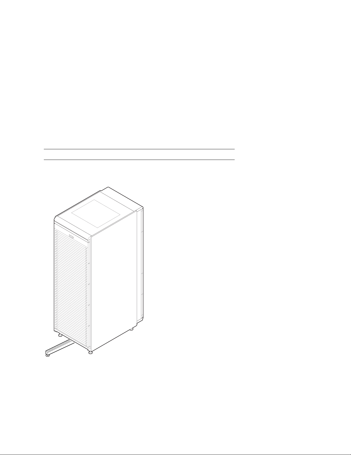
Figure 1-1 shows the H9A10 cabinet with the stabilizer extended.
Figure 1-1 Cabinet
1–2
DIGITAL Server 7300/7300R Series
PK-0625-96

About the Cabinet
• The cabinet contains the following components:
• Cabinet panel with fan and AC power-on LEDs
• Flushing fans
• Two AC power controllers, each with an AC circuit breaker
• Vertical mounting rails
• Stabilizer bar
• Wrist strap for static discharge protection
Cabinet Variants
The H9A10 cabinet has two variants. The H9A10-EL (domestic) cabinet contains two 120
V power controllers, each with 10 NEMA 5-15R outlets. The H9A10-EM (European)
cabinet has two 240 V power controllers equipped with 12 IEC C13 outlets.
Cabinet Configuration Rules
• The maximum number of system drawers is three.
• The maximum number of StorageWorks shelves in a one-system drawer cabinet is
eight.
Configuration Rules
• The maximum number of StorageWorks shelves in a two-system drawer cabinet is six.
• The maximum number of StorageWorks shelves in a three-system drawer cabinet is
two.
DIGITAL Server 7300/7300R Series
1–3

Configuration Rules
System Drawer Configuration Rules (Cabinet)
The H9A10 (RETMA) cabinet rails have a total of 34 U-units with 102
mounting holes. Table 1-1 gives the mounting holes to be used for a cabinet
containing one to three system drawers.
Figure 1-2 System Drawer Mounting Holes
Front
H9A10
Rear
61
60
59
37
36
35
13
12
11
Drawer 3
Drawer 2
Drawer 1
PK-0629-97
1–4
DIGITAL Server 7300/7300R Series

Configuration Rules
The H9A10 cabinet rails have a total of 34 U-units of vertical mounting height. Each Uunit is 1.75 inches in length. When you install a system drawer, begin counting the
mounting holes from the rail bottom to top. According to how many system drawers you
install, mark off the mounting holes listed in Table 1-1.
Table 1-1 H9A10 System Drawer Mounting Holes
One System Drawer Two System Drawers Three System Drawers
11, 12, 13 First: 11, 12, 13 First: 11, 12, 13
Second: 35, 36, 37 Second: 35, 36, 37
Third: 59, 60, 61
DIGITAL Server 7300/7300R Series
1–5
Configuration Rules
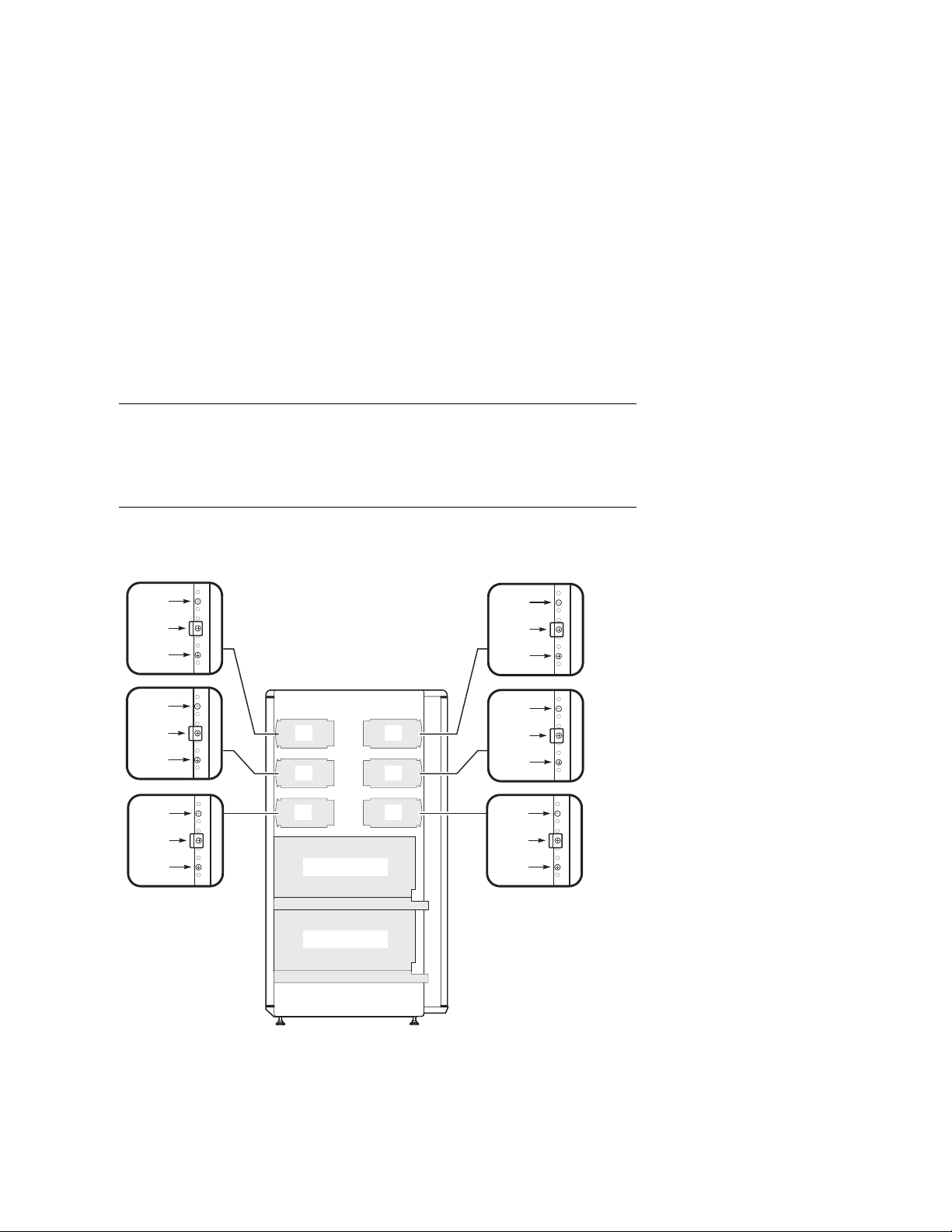
Shelf Configuration Rules (Cabinet)
The maximum number of StorageWorks shelves is eight in a one-system
drawer cabinet. The maximum number of StorageWorks shelves is six in a
two-system drawer cabinet. Figure 1-3 shows shelf placement in a twosystem drawer cabinet. Figure 1-4 shows shelf placement in a one-system
drawer cabinet.
Figure 1-3 Shelves in Two-System Drawer Cabinet
(97)
(94)
(91)
(85)
(82)
(79)
(73)
(70)
(67)
Front
1
2
5
Drawer 2
Drawer 1
(97)
(94)
(91)
Rear
(85)
3
4
6
(82)
(79)
(73)
(70)
(67)
PK-0640-97
1–6
DIGITAL Server 7300/7300R Series
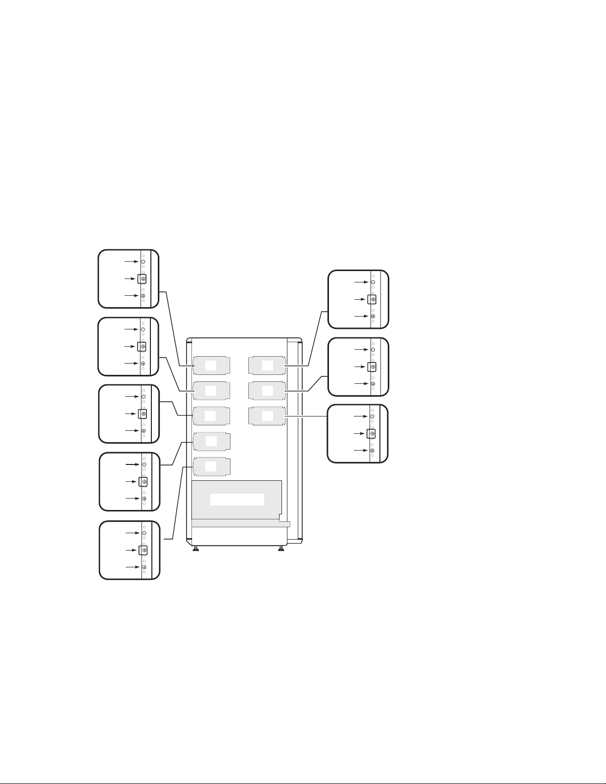
Figure 1-4 Shelves in One-System Drawer Cabinet
(97)
Configuration Rules
(94)
(91)
(85)
(82)
(79)
(73)
(70)
(67)
(61)
(58)
(55)
(49)
(46)
Front
1
2
5
7
8
Drawer 1
(97)
(94)
(91)
Rear
(85)
3
4
6
(82)
(79)
(73)
(70)
(67)
(43)
PK-0640A-97
DIGITAL Server 7300/7300R Series
1–7
Configuration Rules
Pedestal
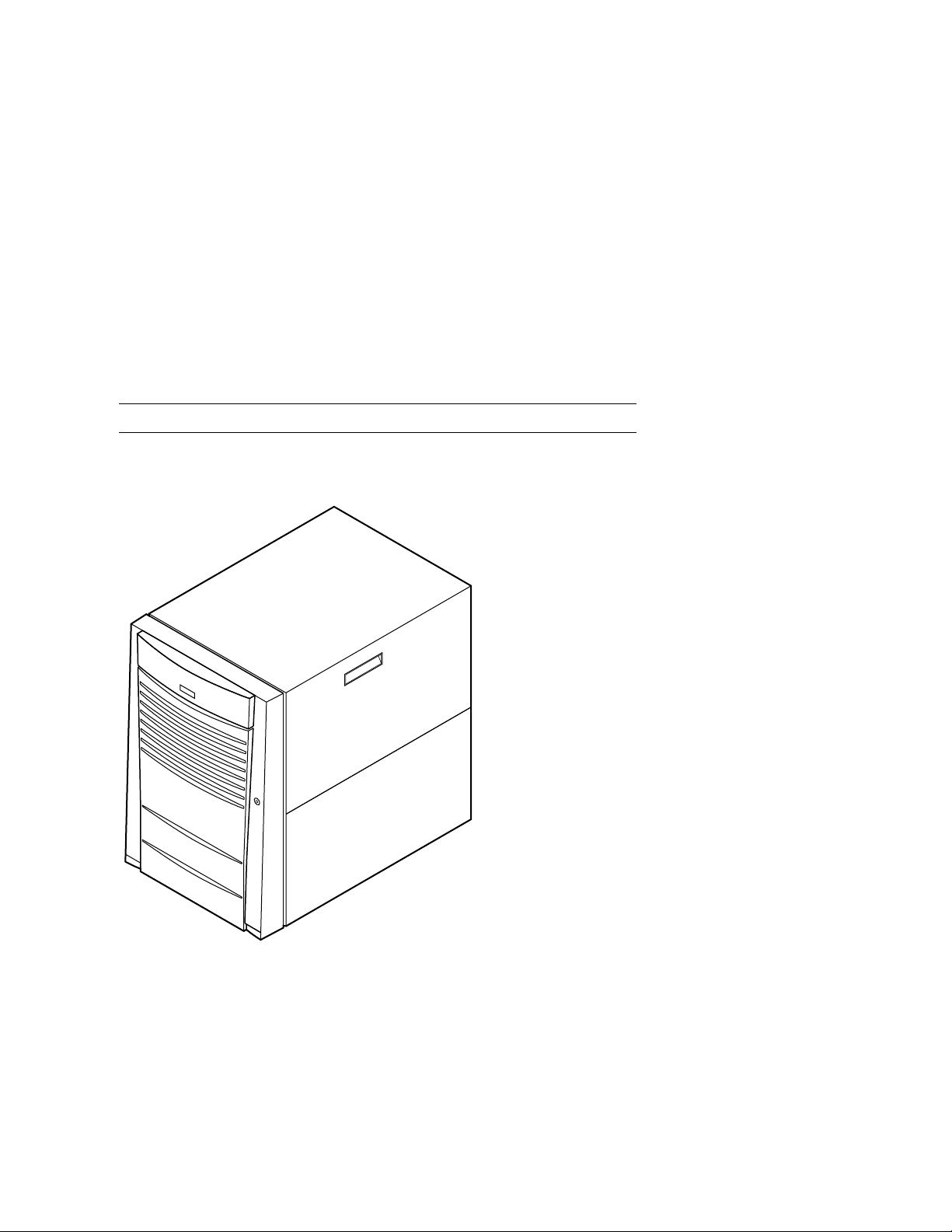
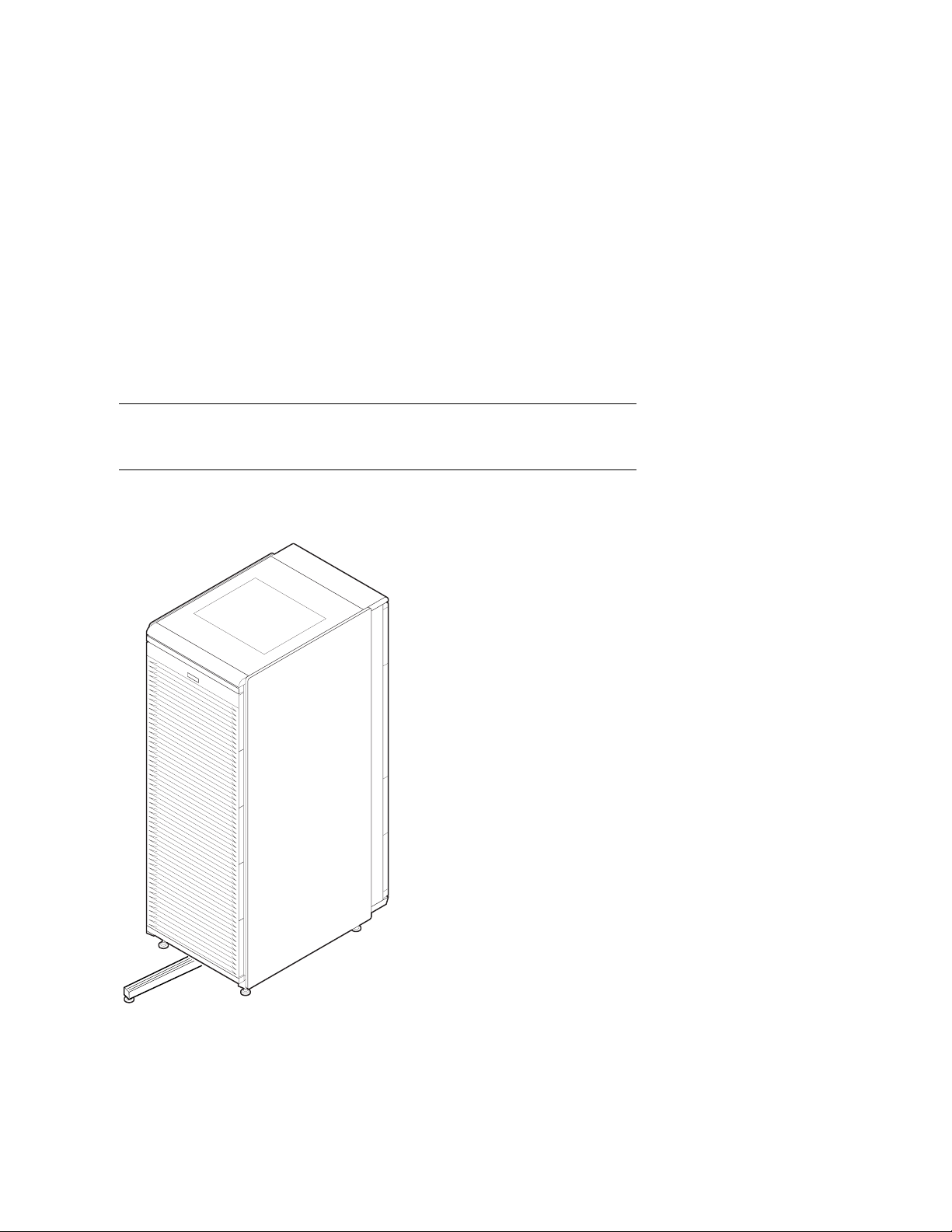
Figure 1-5 shows the pedestal.
Figure 1-5 Pedestal
1–8
DIGITAL Server 7300/7300R Series
PK-0604-96

Pedestal Configuration Rules
• One system drawer is installed in the pedestal.
• The maximum number of StorageWorks shelves is three.
Configuration Rules
DIGITAL Server 7300/7300R Series
1–9

Configuration Rules
System Drawer Power System
The system drawer contains one to three power supplies and distribution
cables. Figure 1-6 shows the power components in the system drawer. Two
AC power controllers complete the power system. See “Cabinet Power
System.”
Figure 1-6 System Drawer Power Components
Power Supplies
First
Third
1–10
DIGITAL Server 7300/7300R Series
Second
PK-0657-96

About the System Drawer Power System
• A system drawer can contain up to three power supplies. The correct position of the
three power supplies is shown in Figure 1-6.
• One power supply is required in a system with one or two CPUs.
• A second power supply is required for N+1 redundancy in a single- or dual-CPU
system.
• Two power supplies are required in a system with three or more CPUs.
• Two power supplies are required in a system with two PCI card cages.
• A third power supply is required for N+1 redundancy in a system with three or more
CPUs.
• A power harness connects the power supplies to the system motherboard, PCI
motherboard, system fans, and drives.
NOTE: Three power supplies provide N+1 redundancy in DIGITAL Server
7300/7300R systems with three or four CPUs.
Configuration Rules
DIGITAL Server 7300/7300R Series
1–11

Configuration Rules
Cabinet Power System
Figure 1-7 shows the two AC power controllers located at the bottom rear of
the cabinet. The system drawer power cable(s) connect to the controllers.
The controller power cables plug into a wall outlet.
Figure 1-7 Cabinet Power Controllers
1
1–12
DIGITAL Server 7300/7300R Series
PK-0692-97

About the Cabinet Power System
The power controllers connect to an AC wall outlet. Each controller has a main power
switch and 10 outlets for system drawers, StorageWorks shelves, and fan tray. When
connecting system components to the controllers, note that system drawer power cables are
gray; StorageWorks shelf power cables and fan tray power cables are gray. Configuration
rules are:
• A system drawer contains one to three power supplies; each power supply has one
power cable that connects to a power controller.
• A StorageWorks shelf has one power cable; a shelf equipped with a redundant power
supply has two power cables.
• Connect all system drawer power cables to the same AC power controller.
• If a cabinet has three system drawers, connect the power cables as shown in
Figure 1-8.
Configuration Rules
DIGITAL Server 7300/7300R Series
1–13

Configuration Rules
Figure 1-8 Power Connections for Three-Drawer Cabinet
Power
Controller
Power
Controller
Fantray
Drawer 2
Drawer 1
Drawer 3
StorageWorks
StorageWorks
1–14
DIGITAL Server 7300/7300R Series
To Wall Outlets
PK0695-97

AC Power Strips in the Pedestal
Figure 1-9 shows the pedestal with two AC power strips installed.
Figure 1-9 Pedestal with AC Power Strips
Configuration Rules
PK-0623-96
DIGITAL Server 7300/7300R Series
1–15

Configuration Rules
Configuration Rules for Pedestal AC Power Strips
In pedestal systems, both AC power strip cables plug directly into a wall outlet.
Configuration rules are:
• In North American models: one system drawer and one StorageWorks shelf per AC
power strip
• In European models: one system drawer and two StorageWorks shelves per AC power
strip
• In Japanese models: one system drawer and three StorageWorks shelves per AC
power strip
• A second AC power strip is required if you install a third StorageWorks shelf in a
North American or Japanese model.
• The maximum number of AC power strips is two.
1–16
DIGITAL Server 7300/7300R Series
DIGITAL Server 7300/7300R System Drawer
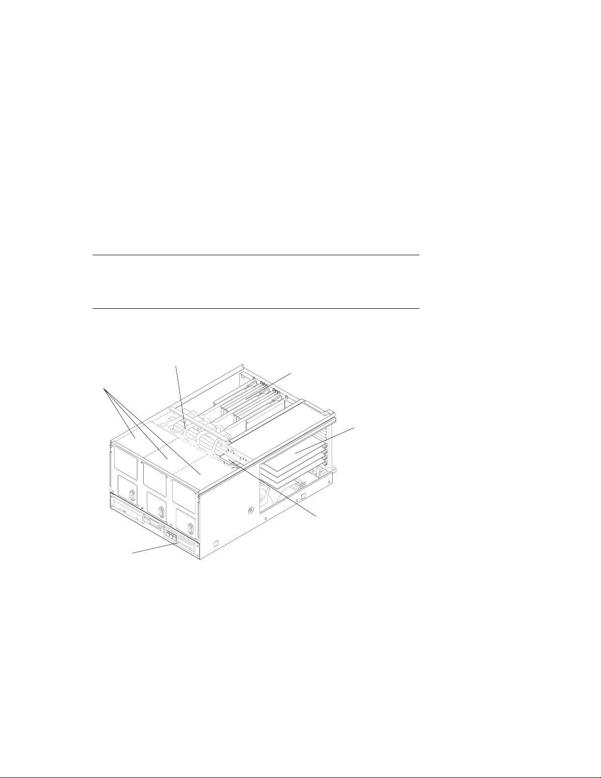
Figure 1-10 shows the components of the DIGITAL Server 7300/7300R
system drawer. See the next section for system motherboard configuration
rules; see the section following that for PCI motherboard configuration
rules.
Figure 1-10 DIGITAL Server 7300/7300R System Drawer Components
Power Cable
CPU and Memory
Power Supplies
Modules
Configuration Rules
PCI Modules
Control
Panel
Fans
PK-0656-96
DIGITAL Server 7300/7300R Series
1–17

Configuration Rules
The DIGITAL Server 7300/7300R system drawer contains the following components:
• CPU card cage containing the system motherboard, CPU modules, memory modules,
and the system bus-to-PCI bus bridge module
• PCI card cage containing PCI motherboard and PCI and EISA modules
• Power supplies and fans
• Control panel
In a cabinet system, the control panel is at the bottom front of the system drawer. In the
pedestal system, the control panel is located at the top front of the enclosure.
Figure 1-11 DIGITAL Server 7300/7300R Control Panel
CD-ROM Drive
Diskette Drive
Control Panel
1–18
DIGITAL Server 7300/7300R Series
PK-0645D-96
DIGITAL Server 7300/7300R System Motherboard
The DIGITAL Server 7300/7300R system motherboard has four processor
slots, eight memory slots, and one I/O slot.
Figure 1-12 DIGITAL Server 7300/7300R System Motherboard
Configuration Rules
CPU3
Mem1H
CPU2
Mem1L
Mem3L
Mem2L
CPU1
Mem0H
Mem3H
Mem2H
CPU0
Mem0L
IOD01
PK-0614-96
DIGITAL Server 7300/7300R Series
1–19

Configuration Rules
System Motherboard Configuration Rules
• The system motherboard has slots for four processor modules.
• The first processor module must occupy slot CPU0.
• The system motherboard has slots for eight memory modules (four memory pairs).
• Memory modules must be configured in matched pairs.
• When large memory pairs are configured with smaller memory pairs, the largest
memory modules must be installed in the lowest order slots.
• The system motherboard has one slot for I/O.
• The power control module (PCM), located on the system motherboard, monitors
voltages, CPU fan RPMs, system fan RPMs, and internal air temperature.
1–20
DIGITAL Server 7300/7300R Series
DIGITAL Server 7300/7300R I/O Interface
The I/O i nterface c onsists of the system bus-to-PCI bus bridge module and
the PCI motherboard. The bridge module is the logical and physical
connection from the system motherboard to the PCI motherboard. The
server control module provides ports for the console terminal, keyboard,
mouse, and other components.
Figure 1-13 DIGITAL Server 7300/7300R PCI Motherboard
PCI1-5
PCI1-4
PCI1-3
PCI1-2
PCI0-5
EISA-3
PCI0-4
EISA-2
PCI0-3
EISA-1
PCI0-2
Configuration Rules
PK-0615-96
DIGITAL Server 7300/7300R Series
1–21

Configuration Rules
I/O Interface Configuration Rules
• The bridge module connects the system motherboard to the PCI motherboard; it is in
slot IOD0/1 on the system motherboard.
• The VGA module must be in a PCI0 slot.
• The PCI motherboard supports two PCI 64-bit buses and one EISA bus.
PCI and EISA Slots
As shown in Figure 1-13, the PCI motherboard has five dedicated PCI slots and three slot
pairs with connectors for a PCI option and an EISA option. You can install an option into
only one member of each pair. Maximum configurations are:
• Eight PCI options using the dedicated PCI slots and the PCI connectors in the three
slot pairs. No EISA options can be installed with this configuration.
• Five PCI options using the dedicated PCI slots and three EISA options using EISA
connectors on the three slot pairs.
NOTE: Multicard options, such as the CIPCA-AA storage adapter, which uses
both one PCI and one EISA slot, or the CIPCA-BA, which uses two PCI slots,
take up two of the eight available option slots.
Server Control Module
The server control module, located at the rear of the system drawer, has ports for the
following devices: terminal (COM1), keyboard, mouse, printer, modem, 12V power, and
an additional communications port (COM2). See Figure 1-14.
1–22
DIGITAL Server 7300/7300R Series

Figure 1-14 Server Control Module Ports
Configuration Rules
Keyboard
Port
12V Pwr
Mouse
Port
COM1
Port
COM2
Port
Parallel
Port
Modem
PK-0624-96
DIGITAL Server 7300/7300R Series
1–23

Configuration Rules
1–24
DIGITAL Server 7300/7300R Series

Preparing the Cabinet
This chapter describes how to prepare the cabinet before installing system drawers and
other components. Sections in this chapter include:
• Cabinet Environmental and Power Requirements
• Unpack and Check Cabinet
• Remove Cabinet from Pallet
• Stabilize the Cabinet
• Joining Two Cabinets
2
DIGITAL Server 7300/7300R Series 2–1

Preparing the Cabinet
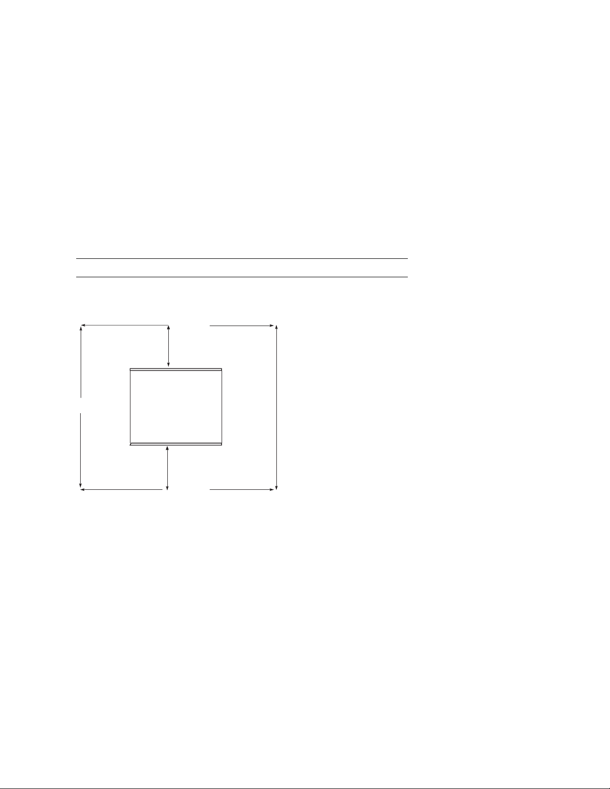
Cabinet Environmental and Power Requirements
Figure 2-1 shows the clearance area necessary for service access.
Figure 2-1 Cabinet Service Area
1 M
(39 in.)
Front
1 M
(39 in.)
Top
Rear
1 M
(39 in.)
1 M
(39 in.)
PK-0631-96
2–2
DIGITAL Server 7300/7300R Series

Preparing the Cabinet
Table 2-1 lists the environmental requirements. Table 2-2 lists the power requirements.
Table 2-1 Cabinet Environmental Specifications
Specification Measurement
Operating temperature 10–35°C (50–95°F)
Relative humidity (non-condensing) 20–90%
Maximum operating altitude 3050 m (10,000 ft)
Minimum operating clearance
Front 60 cm (24 in.)
Rear 60 cm (24 in.)
Table 2-2 Cabinet Power Requirements
Specification Measurement
Maximum current rating 24 A
Operating voltage range 100–120 VAC (North American)
Maximum power consumption Configuration-specific
Operating frequency range 50 Hz to 60 Hz
Tools Required
You will need the following tools to install components in the cabinet:
• Phillips screwdriver
• Adjustable wrench
220–240 VAC (Europe)
DIGITAL Server 7300/7300R Series
2–3

Preparing the Cabinet
Unpack and Check Cabinet
Check to ensure that all system equipment is at the installation site. Then,
unpack the equipment.
Figure 2-2 Cabinet System Inventory
Check Equipment
Against Shipping List
Incomplete or
Damaged
Shipment
No
Missing or
Incorrect
Equipment
No
Continue Unpacking
Yes
Yes
Contact Carrier
Enter in LARS Report
Notify Customer
Contact
Unit Manager
PK-0652-96
2–4
DIGITAL Server 7300/7300R Series

Preparing the Cabinet
If you find a damaged container or package, notify the carrier.
Compare items listed on the Product Delivery Document with the packing slip contained
in a plastic envelope on the shipping box. Items should be compared throughout the
installation procedure as boxes are unpacked and cabinets opened.
It is important to record information on damaged or opened containers on the Labor
Activity Reporting (LARS) form.
DIGITAL Server 7300/7300R Series
2–5

Preparing the Cabinet
Remove Cabinet from Pallet
Check the c abinet f or external damage. Re move the four shipping brac kets
that attach the cabinet to the pallet. Insert the ramps on the front of the
pallet and remove the cabinet.
Figure 2-3 Removal from Pallet
2–6
DIGITAL Server 7300/7300R Series
PK-0649-96

Preparing the Cabinet
WARNING: At least two people are required to remove the cabinet from the
pallet.
WARNING: Serious injury may result if the cabinet is improperly handled or
proper safety conditions are not met.
1. Check the cabinet sides, top, and front and rear doors for damage. Report any damage
to the cabinet to the customer and your unit manager. Stop unpacking until the
customer gives you permission to continue.
2. Using an adjustable wrench, remove the four bolts and shipping brackets that hold the
cabinet leveler feet to the pallet.
3. The leveler feet are lowered to the pallet surface for shipment. Using the adjustable
wrench, raise the feet to the uppermost position before removing the cabinet from the
pallet (see Figure 2-5).
4. Attach the ramps by fitting the prongs into the holes on the front of the pallet. Place
the ramps so that the runners are on the inside. Align the arrows on the ramps and
pallet.
5. With two people working together (one in front and one in back) slowly roll the
cabinet off the pallet down the ramps. Move the cabinet into position.
DIGITAL Server 7300/7300R Series
2–7
Preparing the Cabinet
Stabilize the Cabinet
The cabinet stabilizer bar is attached to the bottom of the cabinet. After
removing the cabinet from the pallet, lower the cabinet leveler feet and then
pull out the stabilizer bar.
Figure 2-4 Using the Cabinet Stabilizer Bar
2–8
DIGITAL Server 7300/7300R Series
PK-0625-96

Preparing the Cabinet
1. Using an adjustable wrench or your hand, lower and adjust the leveler feet (Figure 2-
5). Once the cabinet is level, lock each of the leveler feet in place by tightening the
locknut at the top of each foot.
2. At the front of the cabinet, pull out the stabilizer bar from underneath the cabinet (see
Figure 2-4). Adjust the leveler foot at the end of the stabilizer bar.
WARNING: Only DIGITAL Customer Service representatives or customer
maintenance personnel who are familiar with computer hardware
should slide system drawers out of the cabinet. Personnel should
be experienced and trained in installing computers and related
equipment. Before pulling a system drawer out, make sure that the
stabilizer bar is fully extended; then adjust the leveler foot at the
end of the bar so that it touches the floor.
Figure 2-5 Leveler Foot Adjustment
Screw
Leveler
Foot
PK-0643-96
DIGITAL Server 7300/7300R Series
2–9

Preparing the Cabinet
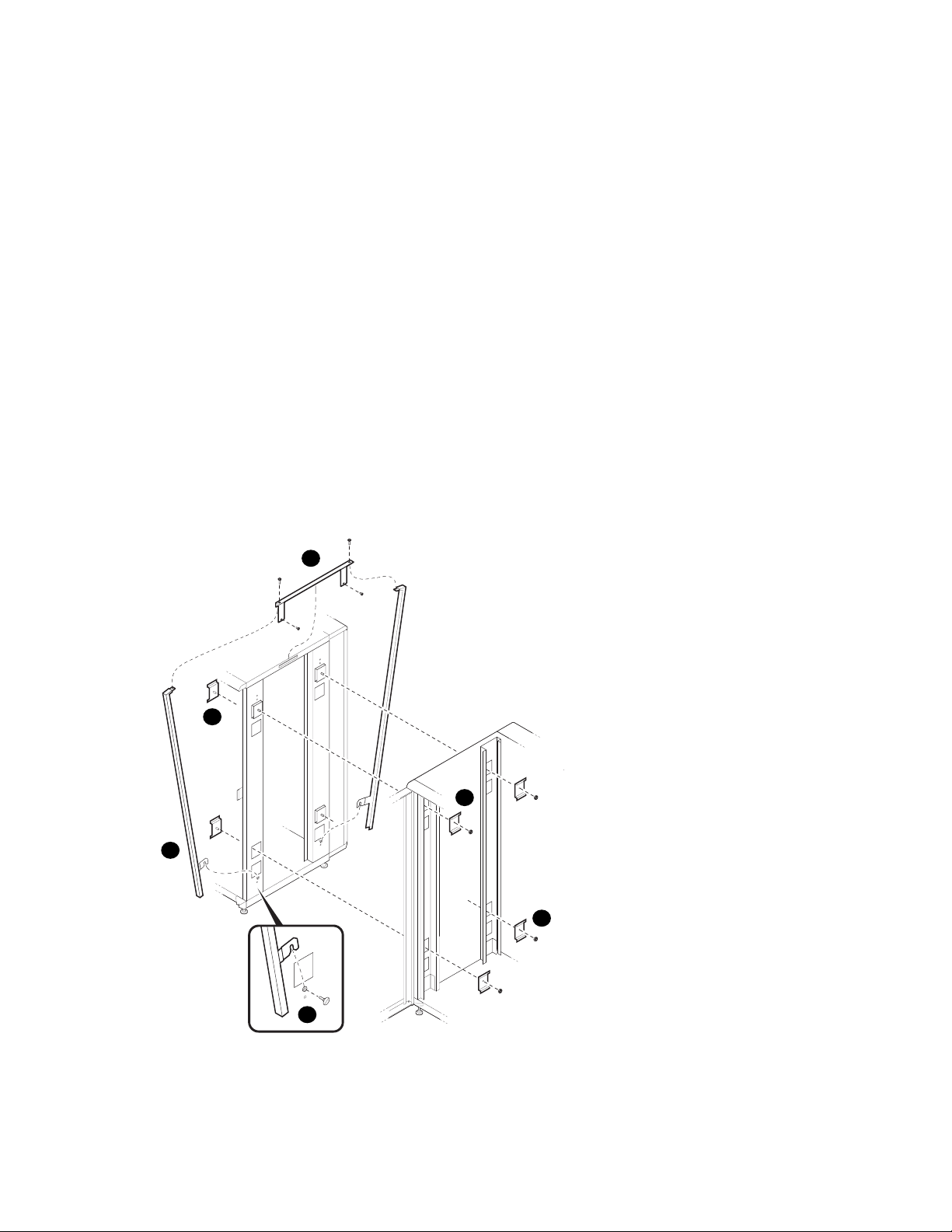
Joining Two Cabinets
First, position the two cabinets side by side. Then, remove the inner side
panels from each cabinet. Finally, install the joiner kit hardware and attach
the cabinets together.
Figure 2-6 Side Panel Removal
2
1
2–10
DIGITAL Server 7300/7300R Series
PK-0647-96
Preparing the Cabinet
1. Position the cabinets side by side.
2. To remove a side panel, remove the two M5 screws at the bottom front and rear of the
cabinet (see
3. Remove the side panel by lifting it up and away from the cabinet. The side panel rests
on the hanger bracket located at the top of the cabinet (see
4. Repeat steps 2 and 3 on the other cabinet. Install the keybuttons (see
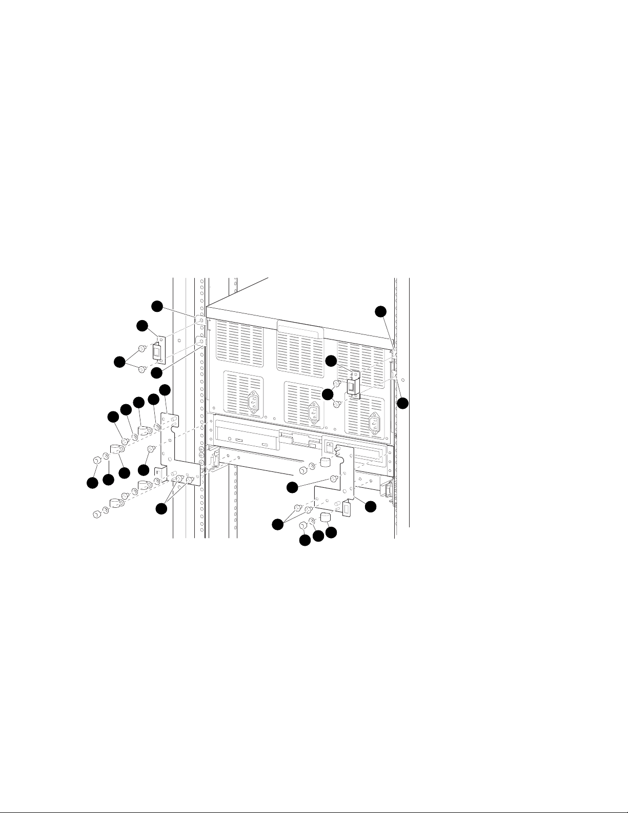
Figure 2-7 Installing the Joiner Hardware
6
➊
).
➋
).
➌
).
5
4
8
7
3
PK-0648-96
DIGITAL Server 7300/7300R Series
2–11

Preparing the Cabinet
5. Install a black bracket at the upper front rail area in one cabinet (see ➍ ).
6. Install the top trim piece using two Phillips screws (see
7. Push the cabinets together.
8. Install a black bracket (
cabinets by bolting the brackets together.
9. Repeat the bracket installation at the space provided at the bottom rear of the
cabinet (see
10. Install the front barrier piece by resting it on the keybutton (step 5) and attaching
it to the cabinet top (see
11. Level the cabinets.
➐
➎
).
➏
) in the same area in the other cabinet. Attach the
).
➑
).
2–12
DIGITAL Server 7300/7300R Series

3
Preparing the Pedestal
This section gives environmental requirements and unpacking guidelines for the pedestal.
Sections include:
• Pedestal Environmental and Power Requirements
• Unpack and Check Pedestal
DIGITAL Server 7300/7300R Series 3–1
Preparing the Pedestal
Pedestal Environmental and Power Requirements
Figure 3-1 shows the clearance area necessary for service access.
Figure 3-1 Pedestal Service Area
60 cm
(2 ft)
Front
60 cm
(2 ft)
Top
Rear
60 cm
(2 ft)
60 cm
(2 ft)
PK-0606-96
3–2
DIGITAL Server 7300/7300R Series

Preparing the Pedestal
Table 3-1 lists the environmental specifications. Table 3-2 lists the power requirements.
Table 3-1 Pedestal Environmental Specifications
Specification Measurement
Operating temperature 10–35° C (50–95° F)
Relative humidity (noncondensing) 20–90%
Maximum operating altitude 3050 m (10,000 ft)
Minimum operating clearance
Front 60 cm (2 ft)
Rear 60 cm (2 ft)
Table 3-2 Pedestal Power Requirements
Specification Measurement
Maximum current rating 12 A (North American)
10 A (Europe)
Typical power consumption 720 watts (DIGITAL Server 7200/7200R
system)
Operating voltage range 100–120/200–240 VAC
Operating frequency range 50 Hz to 60 Hz
AC power 100–120 V, 12 A, single phase (North
America and Japan)
200–240 V, 10 A, single phase (Europe)
Plug type NEMA 5-15P (North America and Japan)
DIGITAL Server 7300/7300R Series
3–3

Preparing the Pedestal
Unpack and Check Pedestal
Check to ensure that all system equipment is at the installation site. Then,
unpack the equipment.
Figure 3-2 Pedestal System Inventory
Check Equipment
Against Shipping List
Incomplete or
Damaged
Shipment
No
Missing or
Incorrect
Equipment
No
Continue Unpacking
Yes
Yes
Contact Carrier
Enter in LARS Report
Notify Customer
Contact
Unit Manager
PK-0652-96
If you find a damaged container or package, notify the carrier.
Compare items listed on the Product Delivery Document with the packing slip contained
in a plastic envelope on the shipping box. Items should be compared throughout the
installation procedure as boxes are unpacked and cabinets opened.
It is important to record information on damaged or opened containers on the Labor
Activity Reporting (LARS) form.
3–4
DIGITAL Server 7300/7300R Series

4
Installing Components in Cabinet
Some cabinet systems are shipped with factory-installed system drawers and StorageWorks
shelves. However, both components may be ordered separately and slider rail kits are
available when installing additional system drawers. This chapter provides guidelines for
installing the system drawers and StorageWorks shelves in a cabinet. Sections include:
• Installing Slider Rails
• Installing the System Drawer
• Installing a StorageWorks Shelf
DIGITAL Server 7300/7300R Series 4–1

Installing Components in Cabinet
Installing Slider Rails
Attach Slide Assemblies to Cabinet Rails
Figure 4-1 Attaching Slide Assemblies
5
1
4
1
3
5
3
4–2
DIGITAL Server 7300/7300R Series
2
4
LJ-05545.TI0

Installing Components in Cabinet
1. Loosen the three screws and nuts ➊ securing the rear slide bracket to the slide
assemblies (see Figure 4-1). This allows the length of the slide assemblies to be
adjusted between the front and rear mounting rails.
2. Locate the right slide assembly.
3. Place the front slide bracket on the inside of the right front rail and align the holes
from the bottom of the nut plate
rail.
➋
with the four slide bracket holes on the right front
4. Install one screw
front rail. Do not tighten.
5. Place the rear slide bracket on the inside of the right rear rail and align the holes from
the bottom of the nut plate
6. Install one screw and washer in the first hole to secure the rear slide bracket to the
right rear rail. Do not tighten.
7. Install four truss-head screws
right rear rail. Do not tighten.
8. Tighten the three pan-head screws and hex nuts
bracket to the right slide assembly.
9. Attach the left slide assembly to the left front and rear rails by repeating steps 1
through 8.
10. Tighten all screws only enough to allow play for the slides to align when the slide tray
is installed in the cabinet.
➌
and one washer ➍ to secure the front slide bracket to the right
➋
with the four slide bracket holes on the right rear rail.
➎
to secure the rear slide bracket and nut plate to the
➊
that secure the right rear slide
DIGITAL Server 7300/7300R Series
4–3

Installing Components in Cabinet
Mount Slide Tray on Slides
Figure 4-2 Mounting the Slide Tray
2
4
1
2
3
LJ-05546.TI0
4–4
DIGITAL Server 7300/7300R Series

Installing Components in Cabinet
1. Fully extend the slides, then lift the slide tray ➊ and position it so that the inner races
➋
fit into the front end ➌ of the slides (see Figure 4-2).
2. Push the slide tray into the slides until it stops. Push in on the two locking levers
necessary and then push the slide tray into the cabinet.
3. Ensure the slide tray slides smoothly in and out of the cabinet.
4. Tighten the screws that secure each of the rear side brackets and nut plates to the rear
rails.
5. Tighten the screws that secure each of the front side brackets and nut plates to the
front rails.
➍
if
DIGITAL Server 7300/7300R Series
4–5

Installing Components in Cabinet
Installing the System Drawer
Mount the System Drawer on Slide Tray
Figure 4-3 Mounting System Drawer on Slide Tray
3
1
4–6
DIGITAL Server 7300/7300R Series
4
2
5
6
3
4
2
5
1
2
3
1
3
6
LJ-05547.TI0

Installing Components in Cabinet
WARNING: Before mounting the system drawer on the slide tray, ensure that
the cabinet stabilizer is in place.
WARNING: The system drawer, fully configured, weighs 45 kg (100 lbs). Two
people are required to install the system drawer in the cabinet.
1. Extend the slide tray to its fully extended position. The slide locking levers lock when
the slides are fully extended.
2. Lift the system drawer just above the slide tray and then move it back and onto the
slide tray.
3. Carefully position the system drawer until the four mounting holes in the bottom of
the drawer line up with the four mounting holes in the bottom of the slide tray.
4. Secure the drawer using four screws
cable clamps go on each screw under the left side of the slide tray and one cable
clamp goes on each screw under the right side of the slide tray.
5. Install the cable clamps
left and right sides using flat washers
left stud and one cable clamp goes on the right stud.
➍
on the two studs located underneath the slide tray on the
➊
, flat washers ➋ , and cable clamps ➌. Two
➎
and kepnuts ➏. Two cable clamps go on the
DIGITAL Server 7300/7300R Series
4–7
Installing Components in Cabinet
Attach the Brackets
Figure 4-4 Attaching the Brackets
8
9
10
8
2
5
4
5
3
1
4
5
6
3
1
3
9
10
4
5
6
8
8
7
LJ-05548.TI0
4–8
DIGITAL Server 7300/7300R Series

Installing Components in Cabinet
1. Remove the top screw ➊ on the left and right side of the system drawer control panel
assembly (see Figure 4-4). Save the screws for later use.
2. Align the two holes at the bottom of the left catch bracket
left front edge of the slide tray.
3. Secure the left catch bracket to the slide tray with two truss-head screws
4. Secure the left catch bracket to the system drawer by replacing the screw removed in
step 1.
➍
5. Attach a cable clamp
kepnuts
6. Attach a cable clamp to each standoff on the left catch bracket with flat washers and
kepnuts.
7. Align the two holes at the bottom of the right catch bracket
the right front edge of the slide tray.
8. Secure the right catch bracket to the slide tray with two truss-head screws.
9. Secure the right catch bracket to the system drawer by replacing the screw removed in
step 1.
10. Attach a cable clamp to each of the studs on the right catch bracket with flat washers
and kepnuts.
➏
.
to each stud on the left catch bracket with flat washers ➎ and
➋
with the two holes in the
➌
.
➐
with the two holes in
DIGITAL Server 7300/7300R Series
4–9

Installing Components in Cabinet
Install Cable Management Bracket
Figure 4-5 Installing Cable Management Bracket
1
2
3
5
4
5
4
2
3
3
5
4
LJ-05549.TI0
4–10
DIGITAL Server 7300/7300R Series

Installing Components in Cabinet
1. At the rear of the cabinet, locate the bracket installation holes shown in Figure 4-5.
2. Install a U-nut over each hole. The thread of the U-nuts should face toward the inside
of the cabinet.
➊
3. Secure the cable management bracket
screws
➋
on each rear rail.
➌
4. Secure the three cable clamps
screws
➍
and flat washers ➎.
to the rear edge of the slide tray with truss-head
to the rear rails by installing two truss-head
DIGITAL Server 7300/7300R Series
4–11
Installing Components in Cabinet
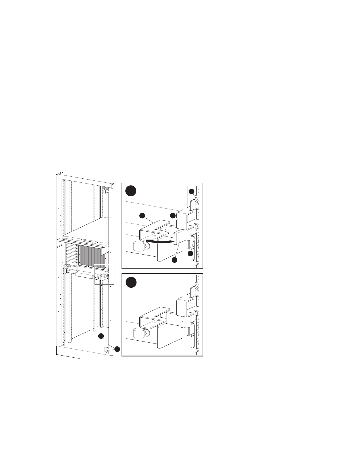
Install Interlock Actuator Assembly
Figure 4-6 Installing the Interlock Actuator
1. Mount the interlock actuator ➊ on the left rear of the slide tray using two kepnuts
(see Figure 4-6).
2. Remove the screws securing the bottom mounting bracket
3. Slide the mounting bracket off the bottom of the vertical bar.
4. Slide the stabilizer bracket
5. Slide the actuator latch
6. Replace the bottom mounting bracket
not tighten.
7. Secure the stabilizer bracket to the left rear rail with two truss-head screws
4–12
DIGITAL Server 7300/7300R Series
1 2
➎
onto the bottom of the vertical bar.
➋
onto the bottom of the vertical bar.
➍
and install the screws removed in step 2. Do
LJ-05550.TI0
➍
(see Figure 4-7).
➏
➋
.
Installing Components in Cabinet
8. Position the actuator latch ➋ to properly engage the interlock actuator ➌, and tighten
the two screws to secure the latch to the vertical bar.
9. Tighten the screws to secure the bottom mounting bracket.
Figure 4-7 Installing Stabilizing Bracket and Latch
A
53
6
6
2
B
1
4
LJ-05551.TI0
DIGITAL Server 7300/7300R Series
4–13

Installing Components in Cabinet
Route the Power Cables
Figure 4-8 Routing Power Cables
6
2
1
3
4
4
5
LJ-05553.TI0
4–14
DIGITAL Server 7300/7300R Series

Installing Components in Cabinet
1. If necessary, remove the old power cables from the system. You must use the power
cables shipped with the slider shelf assembly.
2. Fully extend the slide tray from the cabinet (see Figure 4-8).
➊
3. Connect one end of the power cable(s)
of the system drawer.
NOTE: When routing a power cable, you must remove the cable clamp,
insert the cable in the clamp, and then reinstall it.
4. If the system has one power supply, route the power cable through the inside cable
clamps
5. If the system has a second power supply, route the power cable through the outside
cable clamps on the left catch bracket.
6. Route the power cable through the cable clamps
slide tray. Then route it through the two cable clamps on the left rear edge of the slide
tray
7. Tie-wrap the cable to the cable management bracket
slack in the cable to prevent stress between the slide tray cable clamp and the cable
management bracket.
➌
on the left catch bracket.
➎
.
to the AC input receptacle(s) ➋ on the front
➍
underneath the left side of the
➏
. Ensure that there is enough
8. If the system has a third power supply, route the power cable through the cable clamps
on the right catch bracket. Then continue to route the cable as you did the others,
using the cable clamps underneath the right side of the slide tray.
DIGITAL Server 7300/7300R Series
4–15
Installing Components in Cabinet
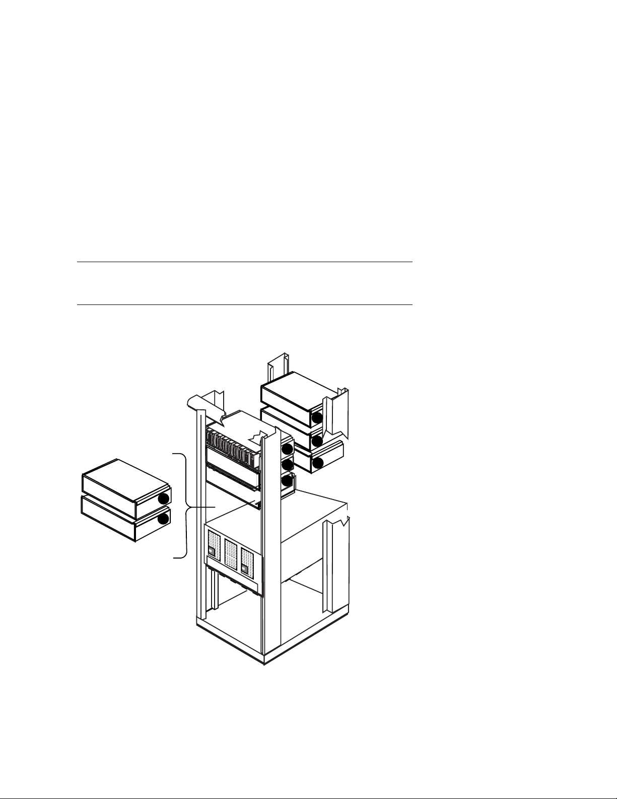
Installing a StorageWorks Shelf
The number of StorageWork s shelves you can instal l depe nds on the number
of system drawers in the cabinet. For example, there is space for eight
StorageWorks shelves in a cabinet with one system drawer. See Figure 4-9.
Figure 4-9 Sample Cabinet Configuration
7
3
4
1
2
5
6
Rear
8
Front
In the H910A cabinet, install the StorageWorks shelf mounting rails as shown in
Figure 4-10.
1. Attach the U-nuts to the appropriate mounting holes.
4–16
DIGITAL Server 7300/7300R Series
PK-0691-97

Installing Components in Cabinet
2. Attach the mounting rail using two screws inserted into the two U-nut mounting holes.
3. Attach the front holding bracket and the two additional screws.
4. Attach the other holding bracket.
5. Install the StorageWorks shelf by sliding it onto the mounting rails.
6. Connect the shelf power cable to an AC power strip. Connect the shelf signal cable to
the SCSI controller in the PCI card cage.
Figure 4-10 Installing Shelf Mounting Rails in H910A Cabinet
Front
PK-0635-96
DIGITAL Server 7300/7300R Series
4–17

Installing Components in Cabinet
4–18
DIGITAL Server 7300/7300R Series

Installing StorageWorks Shelves in
Pedestal
This chapter describes how to install the StorageWorks shelves in the pedestal.
• Installation proceedure
5
DIGITAL Server 7300/7300R Series 5–1

Installing StorageWorks Shelves in Pedestal
Install the StorageWorks Shelf
You can install a maximum of three StorageWorks shelves in a pedestal.
There is space for two shelves in the front of the pedestal and one in the
rear.
Figure 5-1 Installing a StorageWorks Shelf
5–2
DIGITAL Server 7300/7300R Series
PK-0658-96

Installing StorageWorks Shelves in Pedestal
1. Remove the top cover from the pedestal.
2. Slide the StorageWorks shelf into the pedestal base (see Figure 5-1). The pedestal
base contains three sets of support rails for the StorageWorks shelves.
3. Attach the shelf with the hardware included with the option.
4. Connect the StorageWorks signal cable to the PCI SCSI port.
5. Connect the StorageWorks power cable to the AC power strip.
6. Replace the top cover.
DIGITAL Server 7300/7300R Series
5–3

Installing StorageWorks Shelves in Pedestal
5–4
DIGITAL Server 7300/7300R Series

6
Making Connections
This chapter describes how to connect system components and devices. Sections include:
• Connecting a Serial Terminal
• Connecting a Graphics Monitor
• Connecting the Remote Console Monitor
• Connecting the Ethernet Cable
• Connecting a StorageWorks Shelf
1
1
This section shows a standard serial terminal. This terminal is connected to a single system
drawer. Also available is the optional H4020-AA System Management Kit, a single terminal which
mounts in the cabinet and can connect up to eight system drawers.
DIGITAL Server 7300/7300R Series 6–1
Making Connections
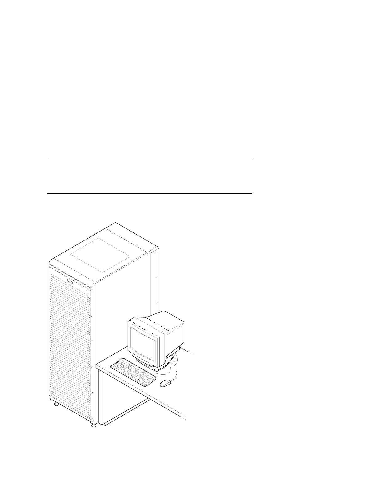
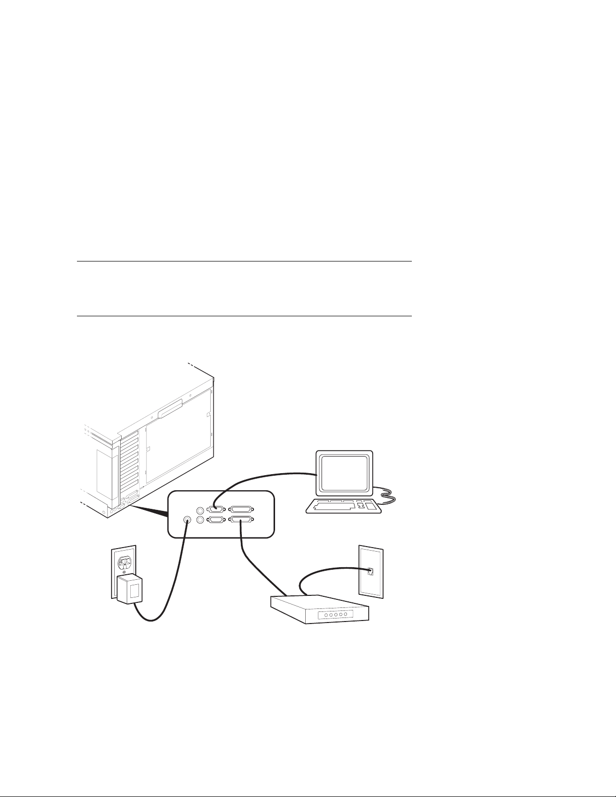
Connecting a Serial Terminal
Figure 6-1 shows the cabinet and a serial terminal. Connect the terminal to
the COM1 port at the rear of the system drawer as shown in Figure 6-2.
Keyboard, mouse, and printer ports are located near the console terminal
port.
Figure 6-1 Cabinet and Console Terminal
6–2
DIGITAL Server 7300/7300R Series
PK-0655-96
Making Connections
1. Unpack the serial terminal, if required. Locate the console terminal signal cable.
2. Connect one end of the cable to the COM1 port located at the rear of the system
drawer (see Figure 6-2). Connect the other end of the cable to the console terminal,
which connects to a 25-pin connector.
3. Connect the keyboard cable to the keyboard port at the rear of the serial terminal.
4. Connect the printer cable to the parallel port.
Figure 6-2 COM1, Serial Terminal Port
COM1
Port
PK-0624A-96
DIGITAL Server 7300/7300R Series
6–3

Making Connections
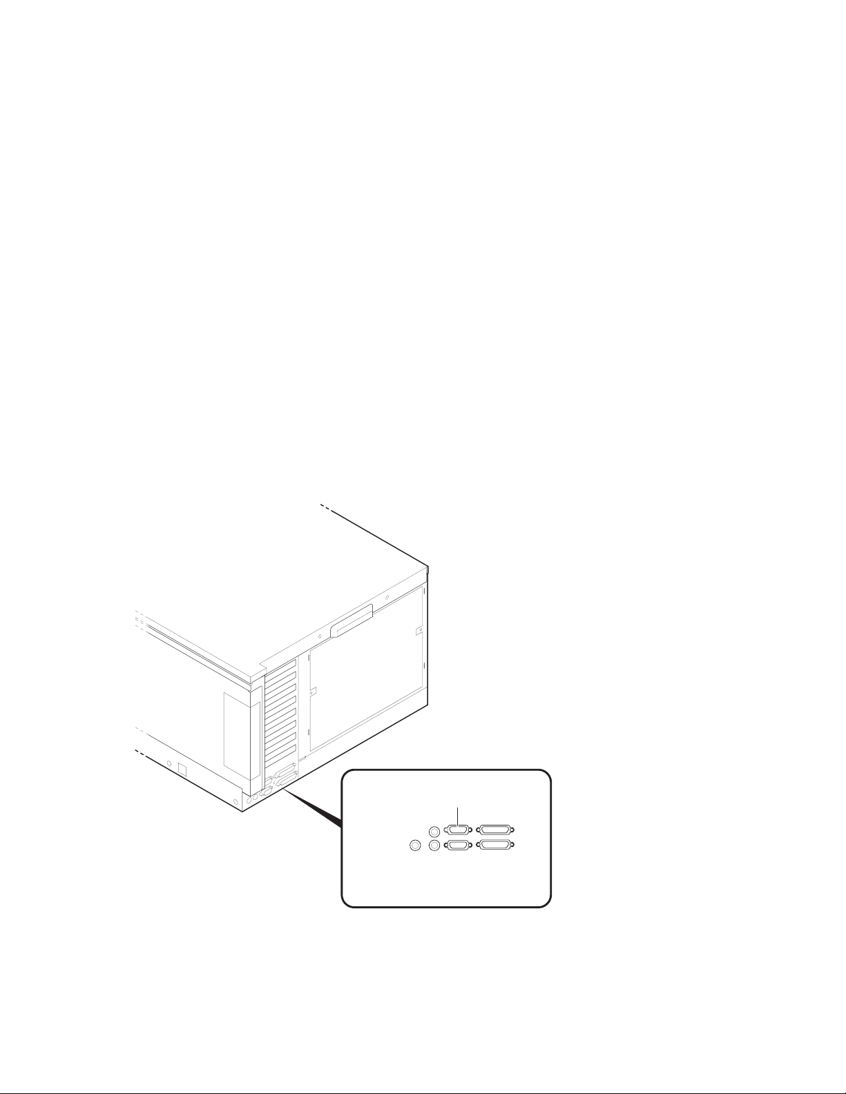
Connecting a Graphics Monitor
Figure 6-3 shows the ports used to connect a graphics monitor. You connect
the graphics monitor to the VGA module in the PCI card cage. Keyboard,
mouse, and printer ports are located at the rear of the system drawer.
Figure 6-3 Graphics Monitor Ports
Keyboard Port
Mouse Port
6–4
DIGITAL Server 7300/7300R Series
Graphics Monitor
Connector
Parallel Port
PK-0663-96

Making Connections
1. Unpack the graphics monitor, if required. Locate the signal cable.
2. Connect one end of the cable to the VGA port in the PCI card cage. Connect the other
end of the cable to the graphics monitor, which connects to a 25-pin connector.
3. Connect the keyboard cable to the keyboard port at the rear of the system drawer.
4. Connect the mouse cable to the mouse port.
5. During power-up, you may want to capture the power-up display on a serial printer.
To do this, connect a serial printer to the parallel port.
DIGITAL Server 7300/7300R Series
6–5
Making Connections
Connecting the Remote Console Monitor
Figure 6-4 shows the connections you make to enable the remote console
monitor (RCM) in a pede stal syst em. The e xternal 12 V power supply is not
required in cabinet systems. See the System Drawer User’s Guide for
instructions on how to operate the RCM.
Figure 6-4 Remote Console Monitor Connections
ConsoleTerminal
External
Power
Supply
1. Connect the external power supply cable to the 12V power port (pedestal systems
only). Connect the other end to a wall outlet (see Figure 6-4).
2. Connect the modem cable to the modem port. Connect the modem to a phone jack.
6–6
DIGITAL Server 7300/7300R Series
Modem
PhoneJack
PK-0651-96
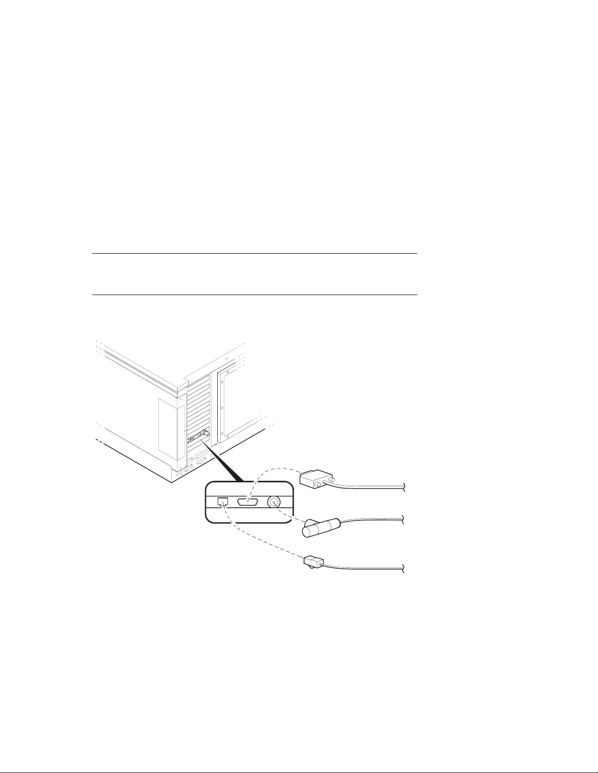
Connecting the Ethernet Cable
If the system includes an Ethernet port, connect the Ethernet cable to the
I/O bulkhead and to the Ethernet transceiver. You can connect ThinWire,
AUI, or twisted-pair Ethernet cables.
Figure 6-5 Ethernet Port
Making Connections
AUI
ThinWire
Twisted Pair
PK-0660-96
1. Connect the transceiver cable to the Ethernet port on the I/O bulkhead (see Figure
6-5).
2. Connect the other end of the cable to the Ethernet transceiver. See the appropriate
Ethernet transceiver manual for more information.
DIGITAL Server 7300/7300R Series
6–7

Making Connections
Connecting a StorageWorks Shelf
When installing an additional StorageWorks shelf, connect the power cable
to an AC power strip; c onnect the signal c able to the SCSI c ontroller at the
I/O bulkhead. See Chapter 1 for cabinet and pedestal configuration
guidelines.
Figure 6-6 SCSI Port
1. Connect the StorageWorks power cable to an AC power strip.
2. Connect the StorageWorks signal cable to the I/O bulkhead at the rear of the system.
6–8
DIGITAL Server 7300/7300R Series
PK-0659-96

7
System Power-Up and Verification
This chapter provides an overview of the power-up procedure, LED checks, and booting.
Sections include:
• Verification Overview
• Turn On Power
• Check Power-Up Test Results
• If Power-Up Fails
– Check Control Panel Message
– Check Module LEDs
– Check Cabinet Power and Fan LEDs
• Show Commands for Installation
• Preboot Tasks
– Setting Environment Variables (EVs)
– Running ECU
– Running Utility Programs
– Updating Firmware
• Booting Windows NT
DIGITAL Server 7300/7300R Series 7–1

System Power-Up and Verification
Verification Overview
Use the following procedure to verify the system after installation.
Figure 7-1 Verification Procedure
1
3
4
Power Up System.
Check Test Results.
Verify SCSI Devices.
2
Perform PreBoot
Boot Operating
System
Tasks
PK-0653-96
7–2
DIGITAL Server 7300/7300R Series

System Power-Up and Verification
➊
When the system powers up, tests run. Verify that all tests have passed by checking
the results in the test display.
➋
Enter the show device command and then check the output against the physical SBBs
(storage building blocks).
➌
Perform preboot tasks such as setting environment variables and running ECU (EISA
Configuration Utility), RCU (RAID Configuration Utility), and LFU (Loadable Firmware
Update).
➍
Boot the operating system.
NOTE: Check all power cable connections from the system components to the
AC power controllers. Make sure that both AC power controller circuit
breakers are On.
NOTE: Before you power up the system, you may want to connect a printer to
the parallel port (located at the rear of the system drawer) to capture the powerup test results.
DIGITAL Server 7300/7300R Series
7–3

System Power-Up and Verification
Turn On Power
Check all power cable connections. Check that the AC power controller
circuit breakers are On. Press the Power button. See Figure 7-2.
Figure 7-2 Control Panel
Power
Halt
Reset
PK-0645C-96
7–4
DIGITAL Server 7300/7300R Series

System Power-Up and Verification
1. Press the Power button to power up the system. The Power button LED lights when
pressed in.
DIGITAL Server 7300/7300R Series
7–5

System Power-Up and Verification
Check Power-Up Test Results
After powering up the system, testing begins and status messages display on
the console terminal and on the control panel display. Check the test results
on the console terminal. Example 7–1 shows a sample display of test results.
Example 7–1 Test Results
SROM V2.0 on cpu0 ➊ #This section displays
SROM V2.0 on cpu1 #on serial terminals
➋
XSROM V2.0 on cpu1
XSROM V2.0 on cpu0
BCache testing complete on cpu1
BCache testing complete on cpu0
mem_pair0 - 128 MB
mem_pair1 - 128 MB
20..20..21..21..23..24..24..
Memory testing complete on cpu1
Memory testing complete on cpu0
starting console on CPU 0
sizing memory #on both serial and
0 128 MB SYNC
1 128 MB SYNC
starting console on CPU 1
probing IOD1 hose 1
bus 0 slot 1 - NCR 53C810
bus 0 slot 2 - DEC KZPSA
bus 0 slot 3 - NCR 53C810
bus 0 slot 4 - DECchip 21040-AA
bus 0 slot 5 - DEC PCI MC
probing IOD0 hose 0
bus 0 slot 1 - PCEB
bus 0 slot 4 - DEC PCI FDDI
bus 0 slot 5 - PBXGA-AA
#only.
➍
➏
➐
#graphics terminals.
➑
➒
➌
➎
#This section displays
configuring I/O adapters...
ncr0, hose 1, slot 1, bus 0
kzpsa0, hose 1, slot 2, bus 0
ncr1, hose 1, slot 3, bus 0
tulip0, hose 1, slot 4, bus 0
floppy0, hose 0, slot 0, bus 1
pfi0, hose 0, slot 4, bus 0
7–6
DIGITAL Server 7300/7300R Series
➓

System Power-Up and Verification
System temperature is 24 degrees C
DIGITAL Server 7200/7200R Console V2.0-1, 24-JUL-1996
10:47:18
P00>>>
NOTE: If the console and the system are configured in graphics mode (SRM
console environment variable (EV) is set to graphics), test information covered
by callouts
to NT, the Windows NT AlphaBIOS console will be loaded by the SRM console,
unless the control panel Halt button is depressed. If this is the case, the SRM
console ignores the os_type setting and halts when the SRM power-up
initialization and configuration is completed.
➊
SRM code runs on each CPU. The processor chips are tested and the path to the
system flash ROM is verified. Each CPU then loads XSROM from the system flash ROM.
➋
XSROM prints banner if it is successfully loaded and started.
➌
XSROM performs local B-cache initialization and testing on each CPU.
➍
XSROM sizes memory via the system IIC bus.
➎
Each CPU participates in memory initialization and testing.
➏
XSROM loads the SRM system console from system flash ROM.
➁
➊
through ➏ will not display. If the SRM console EV os_type is set
➀
➐
Console starts on the primary CPU and proceeds to re-size memory.
➑
The primary CPU, running console, signals each secondary (running XSROM) to start
console.
➒
The primary CPU probes each PCI bus and the EISA bus to size the system.
➓
The primary CPU configures and initializes those I/O adapters requiring initialization.
①
The system temperature is reported.
➁
The console displays its version banner and console prompt.
For a more detailed description of the test results, see the System Drawer User’s Guide.
DIGITAL Server 7300/7300R Series
7–7

System Power-Up and Verification
If Power-Up Fails
Check Control Panel Message
If the console prompt does not appear after test results, check the control
panel message. Figure 7-3 shows the four display fields. Table 7-1 lists the
description of each field.
Figure 7-3 Control Panel Display
2 3
1
4
P0 TEST 11 CPU00
The control panel has a LED display (to control brightness, adjust the potentiometer
located above the control panel Reset button). Status messages are displayed during
power-up testing. Test failure information is also displayed.
NOTE: If an error occurs, you may need to reset the system and observe the
display since display error messages are visible for approximately 4 seconds
before power-up initialization and testing continues.
NOTE: If nothing is displayed on the control panel display and/or the serial
display terminal, check the module LEDs (see”Check Module LEDs”). In
cabinet systems, check the power and fan LEDs (see “Check Cabinet Power and
Fan LEDs”).
7–8
DIGITAL Server 7300/7300R Series
PK-0706E-96

System Power-Up and Verification
Table 7-1 Control Panel Display
Field Content Display Meaning
➊
CPU number P0–P3 CPU reporting status
➋
➌
➍
Status TEST Tests are executing
FAIL Failure has been detected
MCHK Machine check has occurred
INTR Error interrupt has occurred
Test number (for DIGITAL use only)
Suspected device CPU0–3
MEM0–3 and
L, H, or *
IOD0
IOD1
IOD2
IOD3
FROM0
COMBO
PCEB
ESC
NVRAM
TOY
I8242
CPU module number
Memory pair number and low
module, high module, or either
Bridge to PCI bus 0
Bridge to PCI bus 1
Bridge to PCI bus 2
Bridge to PCI bus 3
Flash ROM
6
COM controller
PCI-to-EISA bridge
EISA system controller
Nonvolatile RAM
Real-time clock
Keyboard and mouse controller
2
4
4
5
5
6
6
6
6
3
6
6
2
CPU module
3
Memory module
4
Bridge module (PCI 0 & 1)
5
Bridge module (PCI 2 & 3) (16-PCI slot drawer only)
6
PCI motherboard
DIGITAL Server 7300/7300R Series
7–9
System Power-Up and Verification
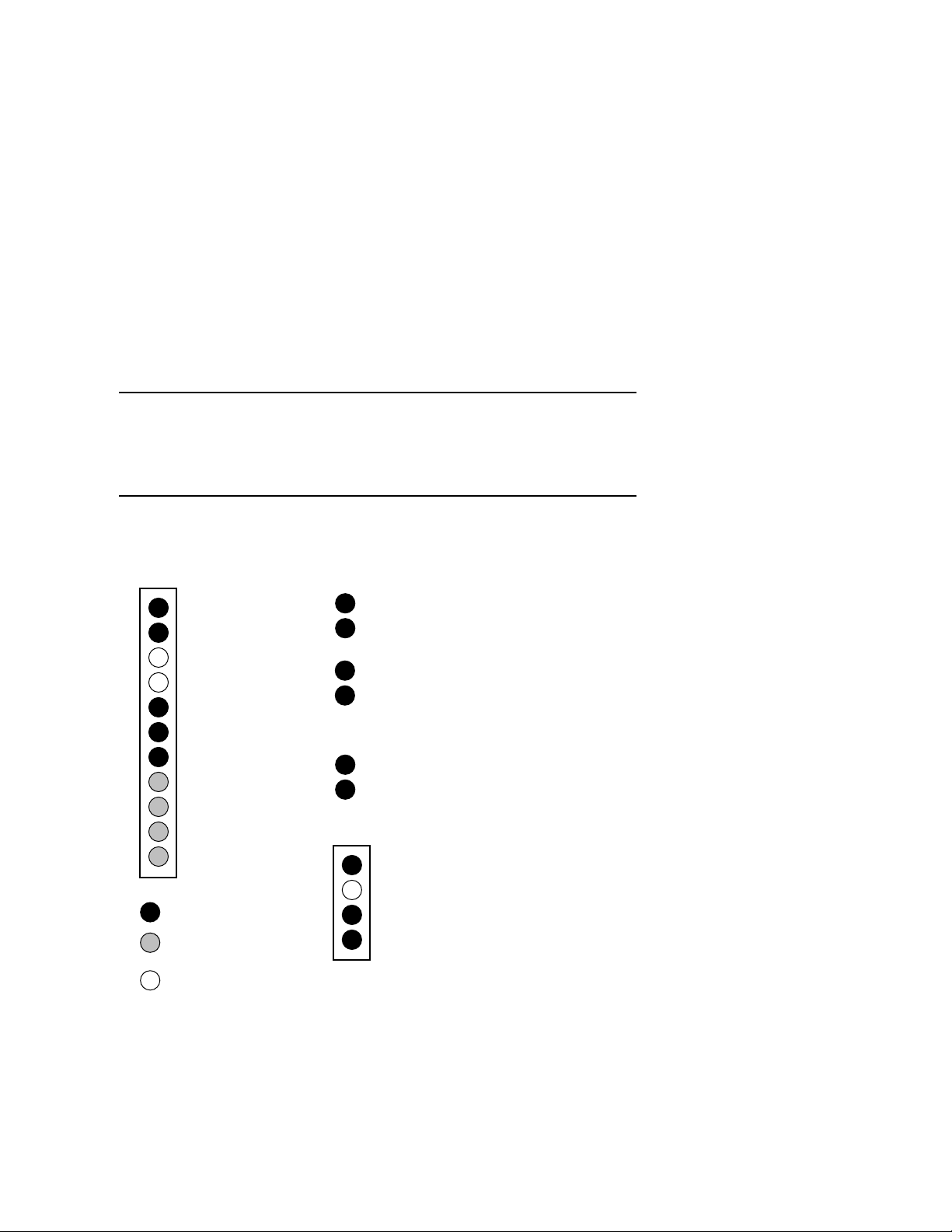
Check Module LEDs
Figure 7-4 shows the CPU, bridge module, and power control module LEDs.
Figure 7-2 lists LED status following a successful power-up. You can see all
module LEDs from the rear of the system drawer. For more information on
troubleshooting procedures, see the DIGITAL Server 7200/7200R Service
Manual.
Figure 7-4 Module LEDs
Power Control Module LEDs Bridge Module LEDs (IOD 0 & 1)
DCOK_SENSE
PS0_OK
PS1_OK
PS2_OK
TEMP_OK
CPUFAN_OK
SYSFAN_OK
CS_FAN0
CS_FAN1
CS_FAN2
C_FAN3
Normally On
Tested at one-second
intervals
Off if power supply not
present or broken
IOD0 Self-Test Pass
IOD1 Self-Test Pass
POWER_FAN_OK
TEMP_OK
Bridge Module LEDs (IOD 2 & 3)
IOD2 Self-Test Pass
IOD3 Self-Test Pass
CPU LEDs
DC_OK
SROM Oscillator
CPU Self-Test Pass
REGULATOR_OK
(B3004 module only)
ML014224
7–10
DIGITAL Server 7300/7300R Series

System Power-Up and Verification
Table 7-2 Module LEDs on Power-Up
LED Power-Up State Description
CPU Module
DC OK On DC power is OK.
SROM Oscillator Off SROM loaded into processor.
CPU Self-Test Pass On Processor chip passed SROM tests.
REGULATOR_OK On Regulator is working.
Base Bridge Module
IOD0 Self-Test Pass On Bridge module passed SROM tests.
IOD1 Self-Test Pass On Bridge module passed SROM tests.
Optional Bridge Module
IOD2 Self-Test Pass
IOD3 Self-Test Pass
POWER FAN OK On Power fan is running.
TEMP OK On Bridge module temperature is OK.
Power Control Module
DCOK SENSE On DC power is okay.
PS0 OK On First power supply is operating.
PS1 OK On (if present) Second power supply is operating.
PS2 OK On (if present) Third power supply is operating.
TEMP OK On Temperature is OK.
CPUFAN OK On CPU fans are OK.
SYSFAN OK On System fans are OK.
CS FAN0 Blinking Fan is OK.
CS FAN1 Blinking Fan is OK.
CS FAN2 Blinking Fan is OK.
C FAN3 Blinking Fan is OK.
DIGITAL Server 7300/7300R Series
7–11

System Power-Up and Verification
Toubleshooting Questions
If a system drawer does not power up, the problem may be a disconnected power cord, a
fan, or a cover interlock. Check the following:
In a pedestal system, is the AC power strip breaker on?
In a cabinet system, is the AC input box breaker on? Are the cabinet fans running? Check
the green FAN LED on the fan tray. Is it on?
Is the system drawer power cord(s) plugged into the AC power strip?
Are the covers on the system drawer closed and the interlocks engaged? The cover
interlocks must be engaged to enable power-up.
7–12
DIGITAL Server 7300/7300R Series
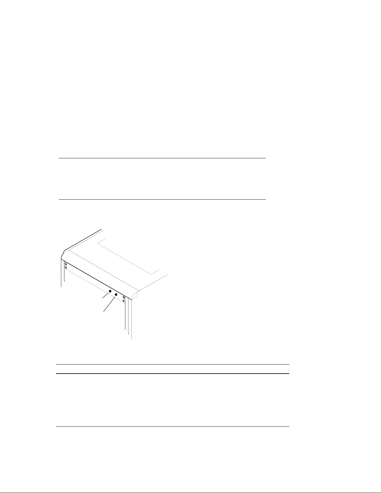
Check Cabinet Power and Fan LEDs
A fan tray with three exhaust fans is located at the top of the cabinet. The
fans are powered by a power supply in the fan tray. A power LED and a fan
LED are located on the fan tray front panel. Figure 7-5 shows the panel
LEDs. See the DIGITAL Server 7300/7300R Service Manual for
troubleshooting information on the cabinet fan tray.
Figure 7-5 Cabinet LEDs
System Power-Up and Verification
Fan LED
Power LED
PK-0664-96
Table 7-3 Cabinet Power and Fan LEDs
LED Power-Up State Description
Power On Fan tray power is okay.
Off Fan tray power supply is broken, or
there is an AC power problem.
Fan Off Fans are okay.
Blinking Replace malfunctioning fan.
DIGITAL Server 7300/7300R Series
7–13

System Power-Up and Verification
Show Commands for Installation
Use show commands to obtain informati on on the system configuration and
power status. These commands are available from the SRM console, which
is reached by powering up the system with the Halt button pressed in.
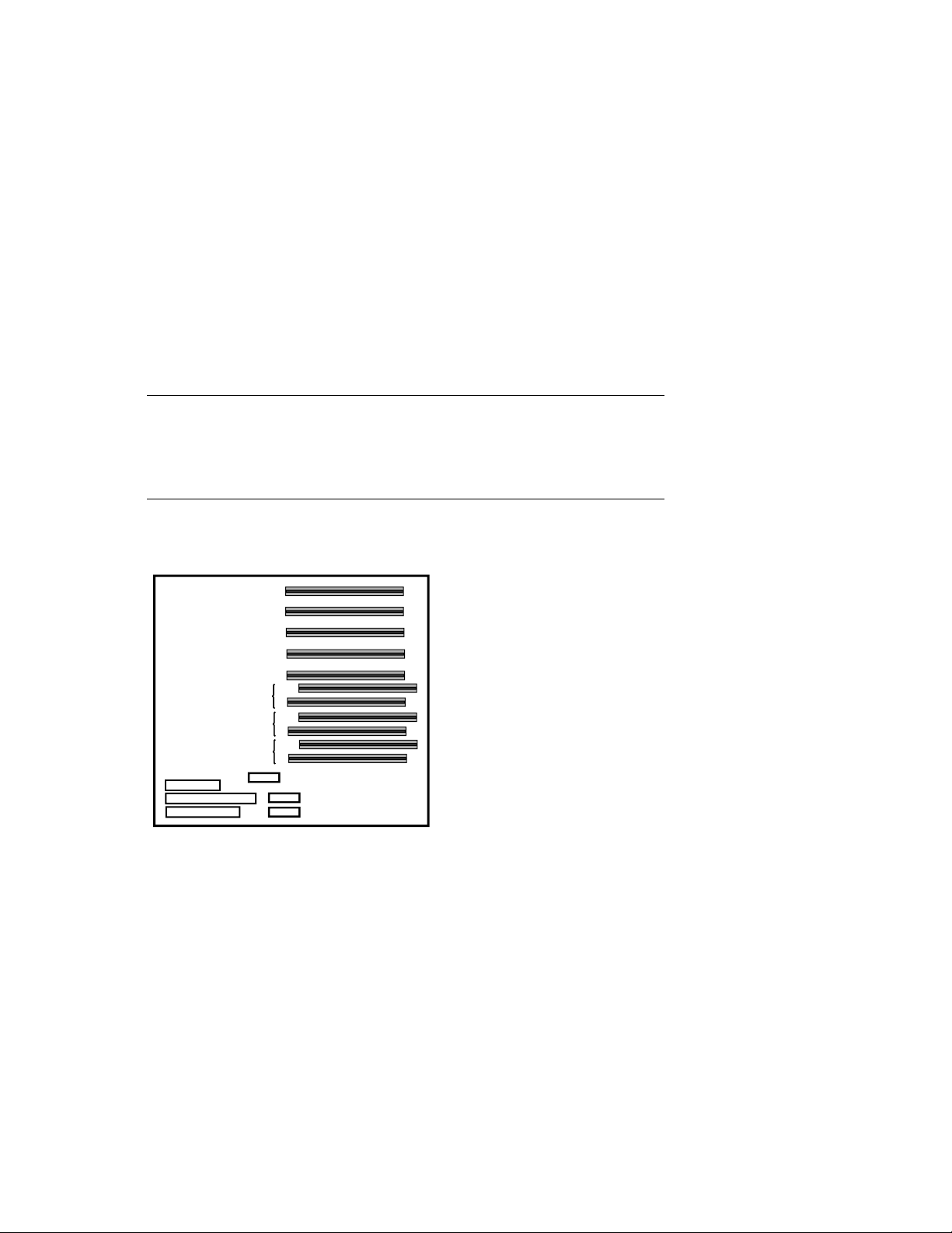
Example 7–2 Show Configuration
P00>>> show config
Digital Equipment Corporation
DIGITAL Server 7300/7300R
Console V2.0-1 OpenVMS PALcode V1.18-8,
Module Type Rev Name
System Motherboard 0 0000 mthrbrd0
Memory 128 MB SYNC 0 0000 mem0
Memory 64 MB SYNC 0 0000 mem1
CPU (1MB Cache) 1 0000 cpu0
CPU (1MB Cache) 1 0000 cpu1
Bridge (IOD0/IOD1) 600 0021 iod0/iod1
PCI Motherboard 8 0000 saddle0
PCI0 (IOD0)
Slot Option Name Type Rev Name
1 PCEB 4828086 0004 pceb0
4 DEC PCI FDDI f1011 0000 pfi0
5 PBXGA-AA 41011 0003 tga0
eisa0 (EISA connected to pceb0)
Slot Option Name Type Rev Name
➊
PCI1 (IOD1)
Slot Option Name Type Rev Name
1 NCR 53C810 11000 0002 ncr0
2 DEC KZPSA 81011 0000 kzpsa0
3 NCR 53C810 11000 0002 ncr1
4 DECchip 21040-AA 21011 0023 tulip0
5 DEC PCI MC 181011 008B mc0
P00>>>
7–14
DIGITAL Server 7300/7300R Series

Example 7–3 Show Power
System Power-Up and Verification
P00>>> show power
Status
Power Supply 0 good
Power Supply 1 not present
Power Supply 2 good
System Fans good
CPU Fans good
Temperature good
The system was last reset via a system software reset
0 Environmental events are logged in nvram
P00>>>
➋
1. ➊ Use the show configuration command to see a listing of the modules in the
system. This command shows the module motherboard or PCI slot number, module
name, module type, revision, mnemonic, and the self-test status of PCI and EISA
modules. In this example, all PCI and EISA modules passed (+) self-test.
2.
➋
The show power command displays status information on the power supplies,
system fans, CPU fans, and system temperature.
For more information on the show commands, see the System Drawer User’s Guide.
DIGITAL Server 7300/7300R Series
7–15

System Power-Up and Verification
Running ECU
The EISA Configurati on Utility (ECU) is used to c onfigure EISA options on
DIGITAL Server systems. ECU is run in AlphaBIOS console mode.
Example 7-4 shows the AlphaBIOS Setup display when run from a serial
terminal.
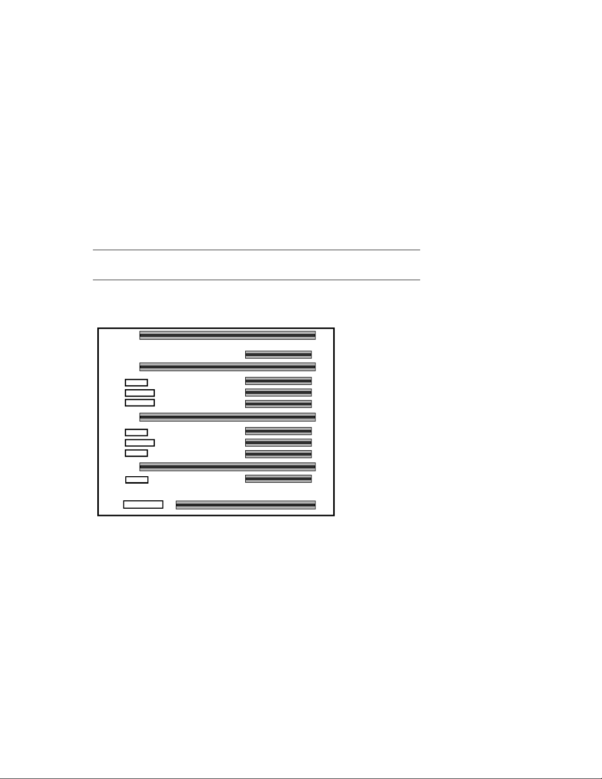
Example 7–4 Running ECU
AlphaBIOS Setup F1=Help
Display System Configuration...
Upgrade AlphaBIOS
Hard Disk Setup...
CMOS Setup...
Install Windows NT
Utilities
About AlphaBIOS...
Run ECU from floppy...
OS Selection Setup...
Run Maintenance Program...
Insert the floppy containing EISA Configuration Utility
(ECU) and press ENTER to run it.
ESC=Exit
When AlphaBIOS is loaded from SRM, it checks to see if there is a graphics card or a
keyboard. If one or the other is absent, then AlphaBIOS directs its output to the console
serial line (top 9–pin connector). It assumes that the terminal connected to this port is a
VT320 or later terminal.
1. Enter alphabios at the console prompt. The top-level AlphaBIOS screen appears.
2. At the top-level AlphaBIOS screen, select the operating system and press Enter to
choose.
3. At the AlphaBIOS Setup screen, select Utilities. Under Utilities, select Run ECU
from floppy. See Example 7–4.
4. Next, insert the floppy containing the EISA Configuration Utility and press Enter to
run it.
7–16
DIGITAL Server 7300/7300R Series
PK-0720B-96

Running Utility Programs
Maintena nce programs such as RAID and EISA configuration utilities are
run from the AlphaBIOS Util ity menu. At the SRM console prompt, ent er
alphabios to bring up the AlphaBIOS console (you must run these utility
programs in AlphaBIOS console mode). Example 7-5 shows the AlphaBIOS
Setup screen and the Run Maintenance Program Dialog box.
Example 7–5 Run Maintenance Program Dialog Box
Display System Configuration...
Upgrade AlphaBIOS
Hard Disk Setup...
CMOS Setup...
Install Windows NT
Utilities
About AlphaBIOS...
Program Name: swxcrmgr.exe
Location:
System Power-Up and Verification
AlphaBIOS Setup
Run Maintenance Program F1=Help
.
A:
A:
ENTER=Execute
CD:
Disk 0, Partition 1
Disk 0, Partition 2
Disk 1, Partition 1
PK-0730A-96
1. At the Setup screen, select Utilities. Press Enter.
2. At the Utilities screen, select Run Maintenance Program. Press Enter.
3. In the Run Maintenance Program dialog box, type swxcrmgr.exe in the Program
Name field.
4. Press Enter to execute the program.
DIGITAL Server 7300/7300R Series
7–17

System Power-Up and Verification
Updating Firmware
The Loadable Firmware Utility (LFU) is used to update firmware on any
module in the system. Example 7-6 shows a sample LFU session; the
firmware load device is the local CD-ROM drive.
Example 7–6 Running LFU
P00>>> lfu
***** Loadable Firmware Update Utility *****
Select firmware load device (cda0, dva0, ewa0), or
Press <return> to bypass loading and proceed to LFU: cda0
Please enter the name of the options firmware files list, or
Press <return> to use the default filename [AS4X00FW]: AS4X00CP
Copying AS4X00CP from DKA500.5.0.1.1 .
Copying [as4x00]RHREADME from DKA500.5.0.1.1 .
Copying [as4x00]RHSRMROM from DKA500.5.0.1.1
...........................
Copying [as4x00]RHARCROM from DKA500.5.0.1.1 .............
--------------------------------------------------------------------
Function Description
--------------------------------------------------------------------
Display Displays the system's configuration table.
Exit Done exit LFU (reset).
List Lists device, revision, firmware name, and update
revision.
Lfu Restarts LFU.
Readme Lists important release information.
Update Replaces current firmware with loadable data image.
Verify Compares loadable and hardware images.
? or Help Scrolls this function table.
--------------------------------------------------------------------
➊
➋
➌
➍
UPD> list
Device Current Revision Filename Update
Revision
AlphaBIOS V5.12-2 arcrom V6.40-1
7–18
DIGITAL Server 7300/7300R Series
➎

System Power-Up and Verification
srmflash V1.0-9 srmrom V2.0-3
UPD> update *
WARNING: updates may take several minutes to complete for each
device.
Confirm update on: AlphaBIOS [Y/(N)] y
DO NOT ABORT!
AlphaBIOS Updating to V6.40-1... Verifying V6.40-1...
PASSED.
Confirm update on: srmflash [Y/(N)] y
DO NOT ABORT!
srmflash Updating to V2.0-3... Verifying V2.0-3... PASSED.
UPD> exit
P00>>>
➊
Enter the lfu command at the SRM console prompt.
➋
The user is prompted to select a firmware load device (for example, CDA0 (local CD-
➏
➐
ROM drive), DUA0 (floppy drive)), or EWA0 (Ethernet). In this example, the user selects
the local CD-ROM drive as the load device.
➌
The user is prompted to enter the options firmware file list. The default filename is
AS4X00FW.
➍
A list of the LFU functions is displayed.
➎
Enter list to get information on each device.
➏
The user enters update * to update firmware on each device.
➐
Enter exit to return to the console prompt.
DIGITAL Server 7300/7300R Series
7–19

System Power-Up and Verification
Booting Windows NT
To boot Windows NT from the AlphaBIOS console, select the correct
version of the operating system from the AlphaBIOS boot screen and press
F2 to enter setup.
Figure 7-6 Booting Windows NT
AlphaBIOS 5.29
Please select the operating system to start:
Windows NT Server 3.51
Use and to move the highlight to your choice.
Press Enter to choose.
AlphaServer
AlphaBIOS boots Window NT in two stages. The first stage involves reading
an OS Loader program from a disk. The name of the OS Loader program is
OSLOADER.EXE. Once the OS Loader program executes, it uses the services provided
by AlphaBIOS to load the operating system.
After the operating system is loaded, the OS Loader starts execution of the operating
system. See the System Drawer User’s Guide or the AlphaBIOS User’s Guide for more
information on the AlphaBIOS interface and boot procedures.
7–20
DIGITAL Server 7300/7300R Series
4000
Family
Press <F2> to enter SETUP
PK-0728B-96
 Loading...