

DEC DIGITAL Server 7100, DIGITAL Server 7100R DIGITAL Server 7000 PowerGrade Installation Guide

TM
DIGIT AL Server 7000 PowerGrade
Installation Guide
Order Number: ER−PC93C−IA. A01
Digital Equipment Corporation

December 1997
The information in this document is subject to change without notice and should not be construed as
a commitment by Digital Equipment Corporation.
Restricted Rights: Use, duplication, or disclosure by the U.S. Government is subject to restrictions as
set forth in subparagraph (c) (1) (ii) of the Rights in Technical Data and Computer Software clause at
DFARS 252.227-7013.
DEC, ServerWORKS, and the DIGITAL logo are trademarks of Digital Equipment Corporation. Intel
and
Pentium are registered trademarks of Intel Corporation. MS-DOS is a registered trademark of
Microsoft Corporation. All other trademarks and registered trademarks are the property of their
respective holders.
1997 Digital Equipment Corporation.
All Rights Reserved.

Contents
Introduction ...........................................................................................1
Kit Contents..................................................................................................1
Tools and Supplies Needed.......................................................................... 2
Processor Compatibility in a Multiprocessor Environment ............................2
Boot the Quick Launch CD-ROM and Create Diskettes.....................2
Enable the On-Board VGA Controller...........................................................3
Power Down the Server................................................................................3
Set Switches on the Main Logic Board......................................................... 6
Replace the Panel and Reconnect the Cables.............................................7
Power Up the Server and Update Your BIOS............................................... 7
PowerGrade Installation .......................................................................7
Remove the CPU Module............................................................................. 8
Install the CPU Chip....................................................................................10
Install the Voltage Regulator Module(s)...................................................... 12
Check the CPU Speed Settings.................................................................. 14
Installing a Second Processor Module (Model 7100)..................................16
Installing a Second Processor Module (Model 7100R) ............................... 17
Reset the Switches on the Main Logic Board ............................................. 18
Processor Module Locations....................................................................... 18
Install the CPU Module(s)...........................................................................19
Install any Video Option Card.....................................................................21
Replace the Panel and Reconnect the Cables...........................................21
Run the System Configuration Utility (SCU).....................................22
Troubleshooting..................................................................................23
Using the Crisis Recovery Diskette if Necessary........................................ 23
Future Updates...........................................................................................23
iii

Figures
Figure 1. Removing the Side Panel (Model 7100)........................................... 4
Figure 2. Removing the Front Bezel (Model 7100R)....................................... 5
Figure 3. Main Logic Board............................................................................. 6
Figure 4. Removing the CPU Module (Model 7100)........................................8
Figure 5. Removing the CPU Module (Model 7100R) .....................................9
Figure 6. Removing the Clip from the Shipping Holder ................................. 10
Figure 7. Removing the New CPU from its Shipping Holder ......................... 11
Figure 8. Installing the New CPU Chip.......................................................... 11
Figure 9. Installing the Clip to Secure the CPU to the CPU Module.............. 12
Figure 10. CPU Module Component Locations............................................. 13
Figure 11. CPU Module Switch Location.......................................................14
Figure 12. Removing the Terminator Card (Model 7100)..............................16
Figure 13. Removing the Terminator Card (Model 7100R)............................ 17
Figure 14. Processor Module Locations......................................................... 18
Figure 15. Installing a CPU Module (Model 7100).........................................19
Figure 16. Installing a CPU Module (Model 7100R) ......................................20
Tables
Table 1. Kit Contents....................................................................................... 1
Table 2. CPU Module CPU Speed Switch Settings.......................................15
Conventions
Symbol Meaning
: Provides general information.
NOTE
WARNING: Indicates the presence of a hazard that can cause
personal injury if the hazard is not avoided.
NOTE
: You may lose data if you have not backed up your
system. If you do not wish to install this kit yourself, contact
DIGITAL Customer Service. For a nominal fee, a Customer
Service Technician can install it for you.
iv

DIGITAL Server 7000 PowerGrade
Introduction
Thank you for purchasing this PowerGrade kit. This kit contains all the
components and instructions required to upgrade your CPU configuration
with additional
Pentium® Pro
DIGITAL Server 7100 or the rack-mounted 7100R. (For a ZX6000, follow
the procedure for Model 7100.)
Installing this kit may involve updating your system BIOS (Basic InputOutput System); however, in most updates this is not necessary.
If you have a PowerGrade with the same processor speed or cache
size as your original CPU, you do not have to update your BIOS. You
install the new CPU, run the System Configuration Utility (SCU), and
you are done.
If you need to update your BIOS because of a change in processor
speed or cache size, you will first need to remove any video option
card, if installed, and enable the internal VGA controller. Once the
BIOS process has completed successfully, you can then reinstall any
video option card. If you need to update your BIOS, you
the new BIOS
before
installing your PowerGrade kit, so the BIOS
recognizes the new processor speed or cache size. This installation
guide provides the necessary details.
processors. This procedure is for either the
must
install
Kit Contents
Table 1. Kit Contents
Item
Pentium® Pro
Voltage regulator module(s)
Antistatic wrist strap
Installation Guide (If needed, some kits may include a CD-ROM for a BIOS upgrade.)
127(,IQHHGHGVRPHNLWVPD\LQFOXGHD&'520IRUD%,26XSJUDGH
CPU chip assembly or Processor module with two CPU chips

DIGITAL Se rve r 7000 Pow erGrade
Tools and Supplies Needed
Phillips screwdriver, 1 pt.
•
Antistatic wrist strap with grounding clip (supplied)
•
Three 3 ½ inch, 1.44 MB high-density MS-DOS formatted diskettes
•
Processor Compatibility in a Multiprocessor Environment
DIGITAL recommends using identical steppings/versions of processors
within a multiprocessor system whenever possible, since these
configurations have received the greatest amount of validation testing.
Since it is not possible to validate every combination of processor
steppings, each new stepping of a processor is fully validated only
against the latest stepping.
incompatibility issues about mixing CPU steppings in a multiprocessor
system
Launch CD-ROM to view the latest CPU compatibility information. If
you have any concerns about processor compatibility within a
multiprocessor system, please contact your local Authorized DIGITAL
Reseller for assistance.
. Please refer to the readme file on the ServerWORKS Quick
At press time, there were no known
NOTE
: If your PowerGrade kit did not contain a CDROM, the upgrade is much easier. Go directly to the
“PowerGrade Installation,” page 8.
Boot the Quick Launch CD-ROM and Create Diskettes
If you received a new CD-ROM, perform this procedure to obtain new
diskettes. During this procedure, you will create a crisis recovery
diskette, BIOS upgrade diskette, and a System Configuration Utility
(SCU) diskette. The Quick Launch CD-ROM contains the latest BIOS,
crisis recovery software, and SCU.
1. Power on your server and boot the ServerWORKS Quick Launch
CD-ROM.
2. Select the “User Documentation” button, then view the Readme file
for CPU compatibility issues.
2

DIGITAL Se rve r 7000 Pow erGrade
3. From the Quick Launch Main Screen, select the “Installations &
Utilities” button and then the Utility tab.
4. Insert a DOS-formatted diskette into drive A, and choose “Crisis
Recovery Diskette,” and select Continue.
5. Insert another diskette into drive A, choose “BIOS Phlash Diskette,”
and select Continue.
6. Insert another diskette into drive A, choose “System Configuration
Utility (SCU)” diskette, and select Continue.
7. Select the BIOS version that you created in step 5 to create the
appropriate SCU diskette.
8. Select Exit to end Quick Launch and remove the CD-ROM.
Enable the On-Board VGA Controller
If your system has an optional video controller, you will need to remove
it and enable the on-board VGA controller. If you are already using the
on-board controller, skip this procedure and go to “Power Down the
Server.”
1. Insert the SCU diskette into drive A and turn on or reset your
server. The diskette should boot automatically.
2. When the SCU title appears, press any key to continue.
Afterwards, follow the instructions on your screen to access the
SCU main menu.
3. From the main menu, use the arrow keys to highlight an item
and then press Enter to select it. Press F1 at any time for help
about a selection.
4. Select the Advanced Control Group and enable the
Embedded - PCI VGA controller.
5. Select Save and Exit to save this selection.
Power Down the Server
1. Turn off your server.
2. Disconnect any external devices, the
monitor power cord.
ac power cord
, and the
3
DIGITAL Se rve r 7000 Pow erGrade
For DIGITAL Server 7100
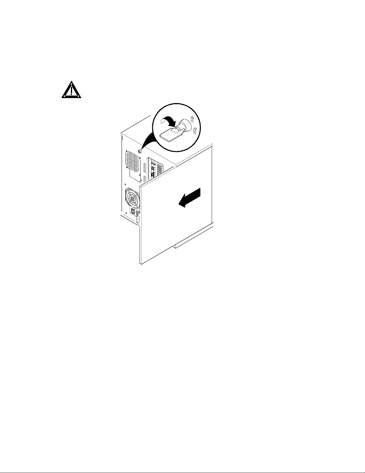
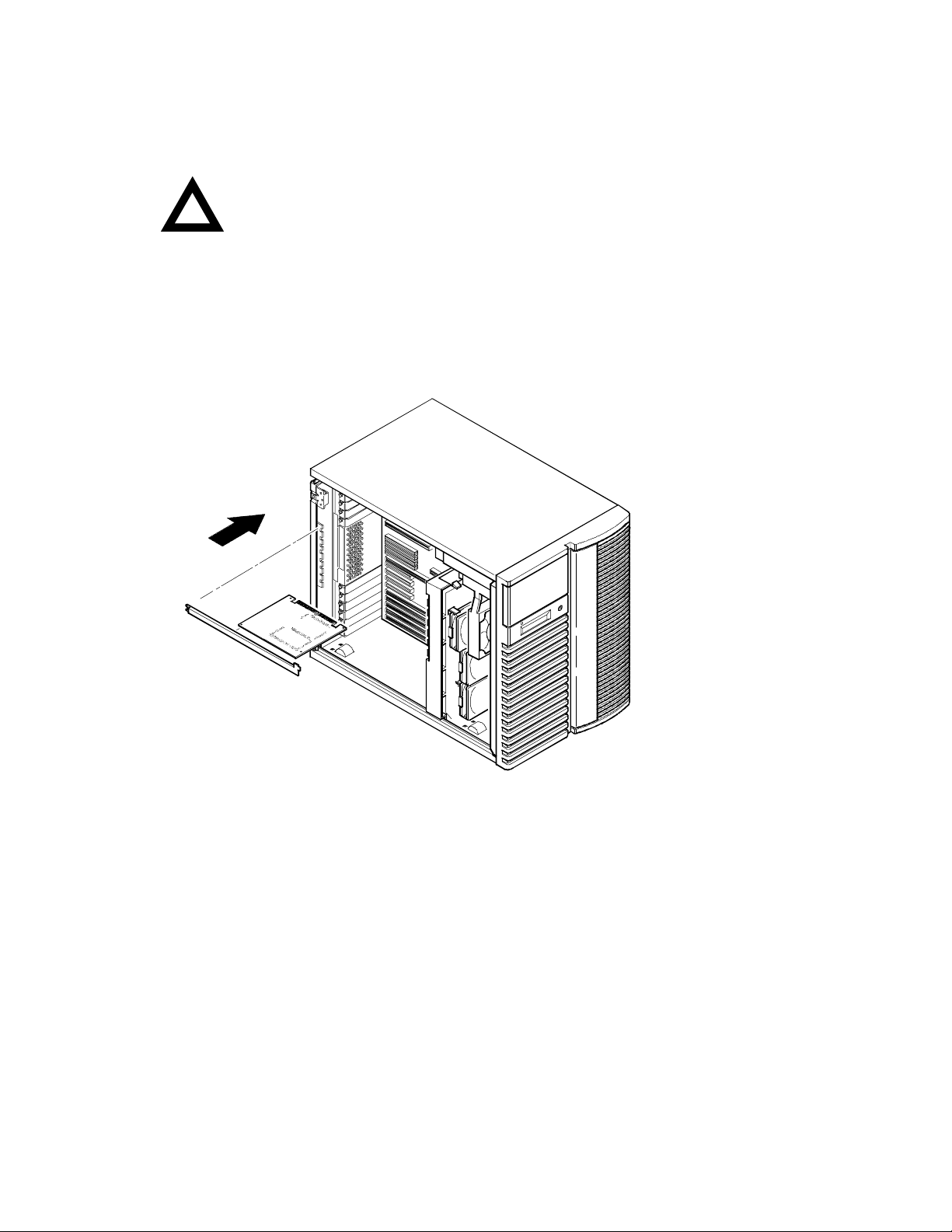
3. Unlock the side panel on the server (Figure 1).
Remove the left side panel by sliding it toward the rear of the
4.
server.
WARNING:
You might injure yourself or damage your server if
you attempt to remove the side panel before unplugging the ac
and monitor power cords.
DEC00405-2
Figure 1. Removing the Side Panel (Model 7100)
4

DIGITAL Se rve r 7000 Pow erGrade
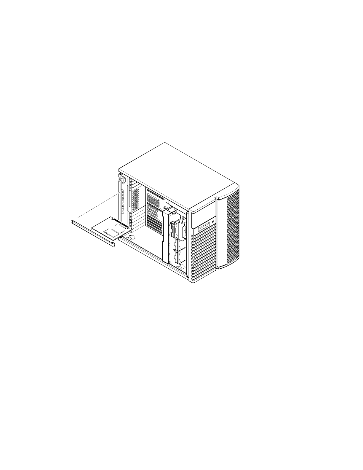
For DIGITAL Server 7100R
3. Remove the front bezel (if installed).
4. Loosen the screws securing the chassis to the rack
rails (Figure 2) and slide the chassis forward until it is
fully extended.
5. Unlock and remove the top cover.
Figure 2. Removing the Front Bezel (Model 7100R)
: If you are not updating your BIOS, skip the next four steps and
NOTE
continue with the “PowerGrade Installation,” page 8.
DEC01336
5
DIGITAL Se rve r 7000 Pow erGrade
Remove any Video Option Card
If present, remove any video option card.
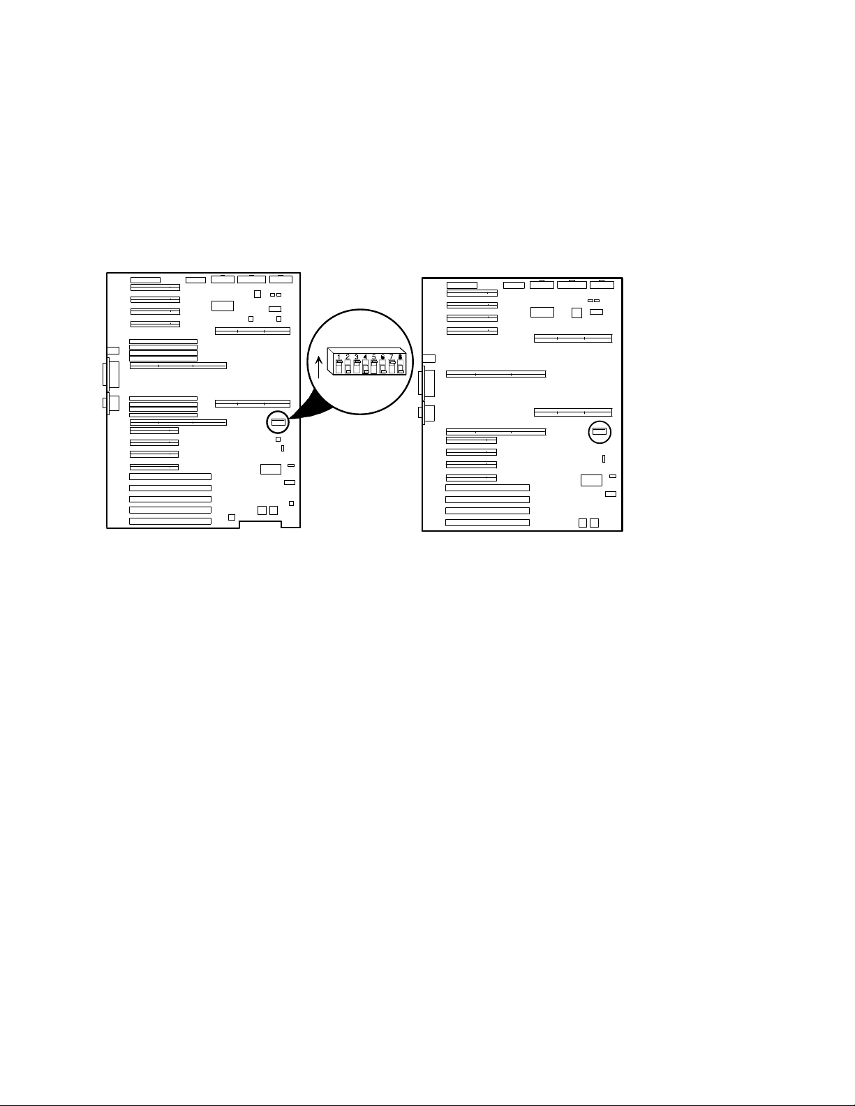
Set Switches on the Main Logic Board
Make sure that the following switches are set:
SW1-1 BIOS upgrade Enabled (On)
SW1-3 Boot block update Enabled (On)
ON
J35
Model 7100
DEC00692-6
Model 7 100R
DEC01320-6
Figure 3. Main Logic Board
6

DIGITAL Se rve r 7000 Pow erGrade
Replace the Panel and Reconnect the Cables
1. Install the left side (top) panel. The server may not power up
with the panel removed.
2. Connect the monitor video cable to the embedded VGA
connector if not already connected.
3. Connect any previously removed cables and the server power
cord to the back of the server.
Power Up the Server and Update Your BIOS
Use the following procedure to update your BIOS:
1. Power up and boot the server with the BIOS Upgrade diskette
installed in drive A.
2. Change the directory to upgrade. Example:
A:\cd upgrade
3. At the MS-DOS prompt, type phlash and press Return.
4. You are prompted with a warning:
***Warning***
You are about to erase the system BIOS in this machine.
Are you absolutely sure? Press “Y” to continue.
5. The BIOS upgrade continues and the system reboots.
NOTE:
has started. If the system loses power, or if at the end of this
procedure the system fails, please refer to the section,
"Troubleshooting – Using the Crisis Recovery Diskette if
Necessary."
DO NOT power down the system once this procedure
6. Remove the diskette from Drive A.
7
DIGITAL Se rve r 7000 Pow erGrade
PowerGrade Installation
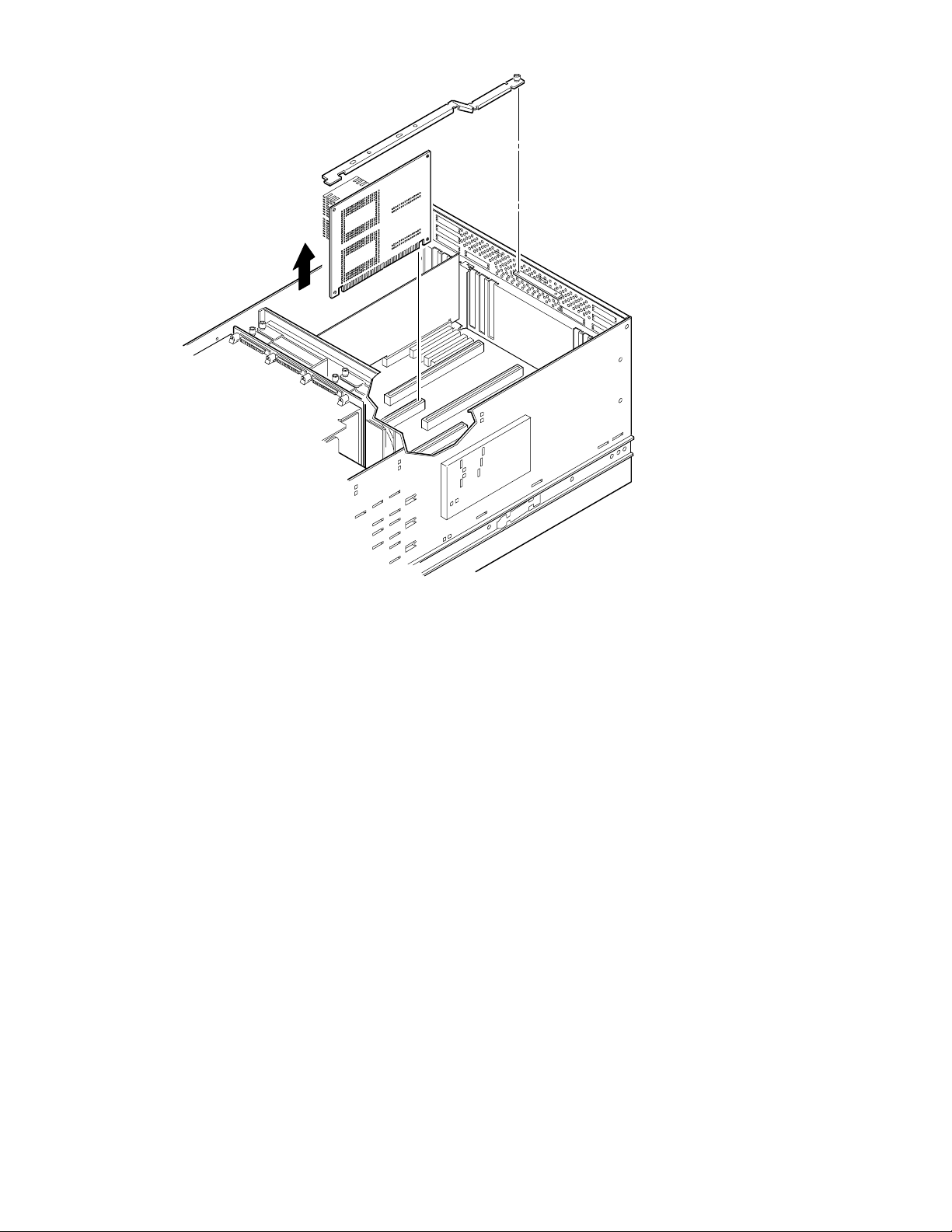
Remove the CPU Module
1. Power down the server, as described on page 3.
2. Place the antistatic wrist strap on your wrist and connect the
grounding clip to a non-painted metal surface of the computer's
chassis.
3. Unscrew and remove the CPU module retaining bracket (Figure
4 or 5).
4. Grasping both ends of the CPU module, carefully remove it from
the main logic board and place it on an antistatic surface.
DEC00695-3
Figure 4. Removing the CPU Module (Model 7100)
8
DIGITAL Se rve r 7000 Pow erGrade
DEC01324-2
Figure 5. Removing the CPU Module (Model 7100R)
9

DIGITAL Se rve r 7000 Pow erGrade
Install the CPU Chip
1. Remove the CPU chip from its shipping holder by removing the
retaining clip. To remove the clip, press down firmly on the top of
the clip. If needed, press down with a small screwdriver in the hole
of the second style clip shown in Figure 6.
DEC01211-2
10
DEC01211-3
Figure 6. Removing the Clip from the Shipping Holder

DIGITAL Se rve r 7000 Pow erGrade
2. Remove the CPU/heat sink assembly from its shipping holder. Do
not pull the heat sink off of the CPU chip. Use care not to bend the
pins.
DEC01232-2
Figure 7. Removing the New CPU from its Shipping Holder
3. On the CPU module, lift up on the lever of the empty CPU socket.
Position the pins of the new CPU chip in the socket of the CPU
module. Note that the pins are denser on one side for correct
orientation.
4. Lower the lever to engage the pins (Figure 8).
DEC01212-3
Figure 8. Installing the New CPU Chip
11

DIGITAL Se rve r 7000 Pow erGrade
5. Install the retaining clip by installing the back side of the clip first,
then pressing it into place as shown in the circle in Figure 9.
DEC01211-4
DEC01211-5
Figure 9. Installing the Clip to Secure the CPU to the CPU Module
12

Install the Voltage Regulator Module(s)
6
1. Remove the new VRM from its shipping container.
2. Install the VRM into the empty VRM socket (Figure 10).
NOTE
: A voltage regulator module must be installed for
each processor that is installed in the server.
DIGITAL Se rve r 7000 Pow erGrade
Figure 10. CPU Module Component Locations
DEC0144
13

DIGITAL Se rve r 7000 Pow erGrade
Check the CPU Speed Settings
Check the switch settings, shown in Figure 11, for the new CPU speed
setting, as listed in Table 2.
1 or 3
2 or 4
UP
J19
14
DEC01408-3
Figure 11. CPU Module Switch Location

DIGITAL Se rve r 7000 Pow erGrade
Table 2. CPU Module CPU Speed Switch Settings
Speed Position Switches J19 Switch Settings
120/133 MHz
150/166 MHz
180/200 MHz*
210/233 MHz
240/266 MHz
270/300 MHz
300/333 MHz
q
UP 4, 8
n
DOWN 1, 2, 3, 5, 6, 7
q
UP 3, 4, 7, 8
n
DOWN 1, 2, 5, 6
q
UP 1, 4, 5, 8
n
DOWN 2, 3, 6, 7
q
UP 1, 3, 4, 5, 7, 8
n
DOWN 2, 6
q
UP 2, 4, 6, 8
n
DOWN 1, 3, 5, 7
q
UP 2, 3, 4, 6, 7, 8
n
DOWN 1, 5
q
UP 1, 2, 4, 5, 6, 8
n
DOWN 3, 7
nnnqnnnq
nnqqnnqq
qnnqqnnq
qnqqqnqq
nqnqnqnq
nqqqnqqq
qqnqqqnq
330/366 MHz
*Default setting.
q
UP 1, 2, 3, 4, 5, 6, 7, 8
qqqqqqqq
15

DIGITAL Se rve r 7000 Pow erGrade
Installing a Second Processor Module (Model 7100)
1. Turn off your server, as described on page 3.
2. Carefully remove the terminator from slot B in the main logic
board, so you can plug in the second processor module (Figure
12).
3. Remove the processor module, two regulators, and retaining
bracket from the antistatic package.
4. Install any additional CPU chip and voltage regulator module (if
necessary), as previously described.
16
DEC00695-5
Figure 12. Removing the Terminator Card (Model 7100)

DIGITAL Se rve r 7000 Pow erGrade
Installing a Second Processor Module (Model 7100R)
1. Turn off your server, as described on page 3.
2. Remove the top cover as described on page 5.
3. Carefully remove the terminator from slot B in the main logic
board, so you can plug in the second processor module (Figure
13).
4. Remove the processor module and retaining bracket from the
antistatic package.
5. Install any additional CPU chip and voltage regulator module (if
necessary), as previously described.
DEC01325-2
Figure 13. Removing the Terminator Card (Model 7100R)
17

DIGITAL Se rve r 7000 Pow erGrade
Reset the Switches on the Main Logic Board
Make sure that the following switches are set to prevent any
unauthorized update to your BIOS (Figure 3, page 6).
SW1-1 Off BIOS upgrade Disabled
SW1-3 Off Boot block update Disabled
Processor Module Locations
Item A in Figure 14 shows the first processor module location. Item B
in shows the second processor module location.
18
A
B
Model 7100
DEC01410-2
Model 7100R
Figure 14. Processor Module Locations
A
B
DEC01320-7
DIGITAL Se rve r 7000 Pow erGrade
Install the CPU Module(s)
1. Install the CPU module(s) into the CPU slot(s) on the main logic
board.
CAUTION:
the corresponding slot. Failure to do so might cause faulty
processor module or server operation.
Also, the processor module has two rows of gold fingers on
its edge that plug into the main logic board slot. The
processor module must be pushed firmly in the slot to
engage both rows of gold fingers or your server might not
power up on boot.
Make sure you align the processor module with
2. Secure the CPU module(s) to the main logic board using the
retaining bracket(s), screw(s), and a Phillips screwdriver.
Figure 15. Installing a CPU Module (Model 7100)
DEC00695-3
19

DIGITAL Se rve r 7000 Pow erGrade
20
DEC01324-3
Figure 16. Installing a CPU Module (Model 7100R)

DIGITAL Se rve r 7000 Pow erGrade
Install any Video Option Card
If you previously removed a video option card, you can install it again.
Replace the Panel and Reconnect the Cables
1. Install the left side (top) panel and lock the server. The server
will not power up with the panel removed.
2.
Model 7100R
using the four previously removed screws. Replace the front
bezel.
3. Connect any cables and power cords previously removed to the
back of the server.
-- Slide the chassis into the rack and then secure
21

DIGITAL Se rve r 7000 Pow erGrade
Run the System Configuration Utility (SCU)
Power up and boot your server from the SCU diskette. The SCU
enables you to check or change your server’s configuration. Run
the SCU to configure your server for the new CPU chip or module.
To start and run the SCU:
1. Insert the SCU diskette into drive A and turn on your server. The
diskette should boot automatically.
2. When the SCU title appears, press any key to continue.
Afterwards, follow the instructions on your screen to access the
SCU main menu.
3. From the main menu, press the up or down arrow to highlight an
item and then press Enter to select it. Press F1 at any time for
help about a selection.
4. From the main menu select Configure Computer and then View
and Edit Details. Example:
If you installed a video option card, select the Advanced Control
Group and disable the Embedded - PCI VGA controller.
5. Select Save and Exit to configure your server for the CPU
module.
6. When complete, remove the SCU diskette from drive A.
7. Move the video cable to the newly installed video card (if you
have one) and reboot your server.
Refer to Chapter 2, “Server Software and Utilities,” in your computer
System Reference manual for any additional information on running the
SCU.
22

DIGITAL Se rve r 7000 Pow erGrade
Troubleshooting
Using the Crisis Recovery Diskette if Necessary
If you updated your BIOS, the crisis recovery diskette may be used only
if your server’s BIOS fails or if a BIOS upgrade is unsuccessful.
When using the Crisis Recovery diskette, you must remove any video
option card and enable the on-board VGA.
1. Turn off the server and set SW1-2 in Figure 3 to ON (Recovery
mode).
2. Insert the Crisis Recovery diskette into drive A and reboot the
computer.
Remember to return the switch to its Normal
:
NOTE
position after using the crisis recovery diskette.
Future Updates
For future reference, you can access product information and software
updates using the Internet at:
http://www.windows.digital.com
or
http://www.windows.digital.com/~ftp/00-index.stm
23
 Loading...