

Page 1

DIGITAL PC 3500/5510
System Reference
Part Numb e r: E R-G2BWW-UA. B01
Digital Equipment Corporation
Page 2

February 1998
The information in this document is subject to change without notice and should not
be construed as a commitment by Digital Equipment Corporation.
Digital Equipment Corporation assumes no responsibility for any errors that might
appear in this document.
The software described in this document is furnished under a license and may be
used or copied only in accordance with the terms of such license. No responsibility is
assumed for the use or reliability of software or equipment that is not supplied by
Digital Equipment Corporation or its affiliated companies.
Restricted Rights: Use, duplication, or disclosure by the U.S. Government is subject
to restrictions as set forth in subparagraph (c) (1) (ii) of the Rights in Technical Data
and Computer Software clause at DFARS 252.227-7013.
DIGITAL PC 3500/5510 System Reference
Copyright Digital Equipment Corporation.
All Rights Reserved.
AMD and Magic Packet are trademarks of Advanced Micro Devices, Inc.
DEC, DIGITAL P C , and the DIGITAL logo are registered trademarks of Digital
Equipment Corporation.
Intel, Pentium Pro and Pentium II are registered trademarks of Intel Corporation.
Microso ft, Windows 95, and Windows NT are registered trademarks of Microsoft
Corporation.
Novell and NetWare are U.S. registered trademarks of Novell Inc.
OS/2 and PS/2 are registered trademarks of International Business Machines
Corporation.
SCO UNIX is a trademark of The Santa Cruz Operation, Inc.
All other trademarks and registered trademarks are the property of their respective
holders.
Page 3

FCC Notice
This equipment has been tested and found to comply with the limits for a Class B
digital device, pursuant to Part 15 of the FCC rules. These limits are designed to
provide reasonable protection against harmful interference in a residential installation.
Any changes or modifications made to this equipment may void the user's authority
to operate this equipment.
This equipment generates, uses, and can radiate radio frequency energy and, if not
installed and used in accordance with the instructions, may cause harmful
interference to radio communications. However, there is no guarantee that
interference will not occur in a particular installation. If this equipment does cause
harmful interference to radio or television reception, which can be determined by
turning the equipment off and on, the user is encouraged to try to correct the
interference by one or more of the following measures:
• Reorient or relocate the receiving antenna
• Increase the separation between the equipment and receiver
• Connect the equipment into an outlet on a circuit different from that to which
the receiver is connected
• Consult the dealer or an experienced radio/TV technician for help
The user may find the following booklet prepared by the Federal Communications
Commission helpful: How to Identify and Resolve Radio-TV Interference Problems.
This booklet is available from the U.S. Government Printing Office, Washington,
D.C., 20402. Stock No. 004-00398-5.
All external cables connecting to this basic unit need to be shielded. For cables
connecting to option boards, see the option manual or installation instructions.
Canadian DOC Notice
This digital apparatus does not exceed the Class B limits for radio noise emissions
set out in the radio interference regulations of the Canadian Department of
Communications.
Page 4

VCCI Notice
This equipment is in the 2nd Class category (information equipment to be used in a
residential area or an adjacent area thereto) and conforms to the standards set by
the Voluntary Control Council For Interference by Data Processing Equipment and
Electronic Office Machines aimed at preventing radio interference in such residential
area.
When used near a radio or TV receiver, it may become the cause of radio
interference.
Read the instructions for correct handling.
German Ergonomic Notice
This equipment meets or exceeds the ergonomic requirements of ZH1/618 and is
certified to bear the GS mark by TUV Rheinland of Germany.
Safety Requirements
This equipment meets or exceeds requirements for safety in the U.S. (UL 1950),
Canada (CSA C22.2 No. 950), and Europe (EN 60950/IEC 950) with Nordic
requirements.
WARNING:
battery is incorrectly r eplaced. To pr event damage to your
computer, be sur e t he + s ide f aces up when ins t alling a new
battery. Also, be sure you r eplace t he bat t er y with either a
DIGITAL (P/N 12-41474-05) , Toshiba (P/ N CR2032), or
equivalent 3 V dc lithium battery.
Depending on your locality, your computer’s battery might be
considered hazardous waste. Make sure you follow
local statute to properly dispose of t he old battery.
There is a danger of battery explosion if a lithium
any state or
Page 5

ADVARSEL:
hvis det udskiftes ukorrekt. Undgå, at beskadige din computer HUSK, at + siden skal vende opad, når du installerer et nyt
batteri. Du skal udskifte batt er iet m ed ent en et DI G I TAL
(delnummer 12-41474-05) , Toshiba (delnum m er CR2032), eller
tilsvarende 3 V jævnstrøms lithiumbatteri.
Afhængig af dit lokalområde, er det m uligt, at din com put er s
batteri betra gtes som farligt affald. Hus k , at følg e ev t. miljølov e og
lokale bestemmelser, når du kasserer det gam le batt er i
Der er fare for, at et lithiumbatteri eksploderer,
.
VAROITUS:
väärin. Estääksesi tietokoneesi vaurioitumisen varmista, et tä
patteria asentaessasi sen positiivinen (+) puoli on ylöspäin.
Tarkista myös, että käyttämäsi uusi patteri on joko DIGITAL (osa
no. 12-41474-05), Toshiba (osa no. CR2032) t ai vast aavanlainen
3 voltin t a s av irtalitiu m p a tteri.
Asuinpaikastasi riippuen tietokoneesi patteria voidaan pitää
ongelmajätteenä. Pidä huoli, että hävität vanhan pat terin
voimassa olevien lakien ja asetusten mukaisesti.
VARNING!
jonbatteri byts ut på felaktigt sätt. Förhindra att datorn skadas
genom att se till at t plus sidan ( +) är uppåt v änd när du sätter i ett
nytt batteri. Det gam la batteriet får endast bytas ut m ot et t
DIGITAL-batter i (ar tikelnummer 12-41454-05), et t Toshiba- bat t er i
(artikelnummer CR2032) eller ett m ot svar ande litiumbatteri på 3
volt likström.
Datorbatterier anses vara miljöfarligt avfall i många länder. Du
måste följa alla lokala bestämmelser när du avyttrar ett gammalt
batteri.
Litiumpatterit voivat r äjähtää, jos ne asennetaan
Det kan förekomma en batter iexplosion om ett litium-
Page 6

Laser Safety Notices
All CD-ROM drives included in DIGITAL compu te r s a r e cl a s si fied as Class 1 laser
products and comply with safety standards as set by U.S. government and applicable
European agencies.
No hazardous radiation is emitted from this CD-ROM drive; the laser beam is
completely enclosed in the CD-ROM subassembly during all customer operation and
maintenance. In the event that repair or service of the CD-ROM subassembly is
required, only authorized DIGITAL servi c e p e rs onnel should perform such repairs.
Energy Star Compliant
Your DIGITA L PC 3500/5510 computer (low profile model only) is ENERGY STAR
compliant when used with Windows 95. DIGITAL advise s th a t yo u d o n o t u s e th e
enable Power Management features with operating systems that do not allow for
power management, such as SCO UNIX, Windows NT, or OS/2.
To ensure that your entire computer system remains ENERGY STAR compliant, you
must use an ENERGY STAR compliant monitor, that is, a monitor that supports the
DPMS protocol.
Page 7

Contents
Preface
Introduction..................................................................................................... ix
Related Material.............................................................................................. ix
Latest Product Information and Updates.......................................................... x
DIGITAL PC 3500/5510 Computers................................................................. x
Features................................................................................................... xi
Chassis Versions...................................................................................... xi
Audience......................................................................................................... xiv
Organization.................................................................................................... xiv
Conventions.................................................................................................... xv
Special Notices................................................................................................ xvi
1
Beyond Quick Setup
Introduction..................................................................................................... 1-1
Front Panel Controls and Indicators................................................................. 1-2
Rear Panel Connectors and Voltage Select Switch .......................................... 1-4
Typical CD-ROM Front Panel (not available on all models) .............................. 1-6
Removing your Computer’s Outside Cover ...................................................... 1-8
SecureBOX (DIGITAL PC 5510 Only)....................................................... 1-10
Replacing your Computer’s Outside Cover....................................................... 1-12
Chassis Lockdown........................................................................................... 1-14
Attaching the Hasp (Low Profile Computers)............................................. 1-15
Attaching the Hasp (Short Tower Computers)........................................... 1-16
Connecting Speakers (DIGITAL PC 5510 Only)............................................... 1-17
Connecting Headphones (DIGITAL PC 5510 Only).......................................... 1-19
Connecting a Microphone (DIGITAL PC 5510 Only)......................................... 1-20
Connecting a Local Printer............................................................................... 1-22
i
Page 8

Contents
Connecting a Universal Serial Bus (USB) Device............................................. 1-24
Your Computer’s Windows Enhanced Keyboard.............................................. 1-26
Creating a Comfortable Working Environment ................................................. 1-27
2
Using the BIOS Setup Utility
What is the BIOS Setup Utility?....................................................................... 2-1
Accessing the BIOS Setup Utility.............................................................. 2-2
Helpful Hints............................................................................................. 2-3
Changing Your Computer’s Configuration........................................................ 2-5
Changing Time and Date................................................................................. 2-5
Setting Up Security.......................................................................................... 2-5
Setting Supervisor and User Passwords ................................................... 2-6
Enabling Password On Boot..................................................................... 2-7
Eliminating User and Supervisor Passwords ............................................. 2-8
Protecting Against Boot Sector Viruses..................................................... 2-8
SecureBIOS ...................................................................................... 2-9
Other Security Options............................................................................. 2-10
Remote Network Wake-up (DIGITAL PC 5510 Only) ....................................... 2-11
Setting Power Management Options................................................................ 2-12
Setting up Power Management................................................................. 2-12
Configuring for New Disk Drives ...................................................................... 2-14
Diskette Drive Configuration ..................................................................... 2-14
Hard Disk Drive Configuration................................................................... 2-15
Autotyping a Hard Disk ...................................................................... 2-15
Manually Defining a Hard Disk ........................................................... 2-16
Changing the Boot Priority............................................................................... 2-17
Changing the Hard Drive Sequence................................................................. 2-18
Speeding up the Boot Process......................................................................... 2-19
Resetting Keyboard Features.......................................................................... 2-20
Changing the Keyboard Features.............................................................. 2-21
Flash Utility ..................................................................................................... 2-22
ii
Page 9

3
Inside Your Computer
Introduction..................................................................................................... 3-1
Improving Computer Performance................................................................... 3-2
Preparing Your Computer for Expansion.......................................................... 3-2
Your Computer’s Components and Connectors ............................................... 3-2
Computer Components ................................................................................... 3-2
Main Logic Board Components........................................................................ 3-4
Rear Panel Connectors ................................................................................... 3-6
Main Logic Board Connectors.......................................................................... 3-8
Low Profile Backplane Components and Connectors ....................................... 3-9
Short Tower Backplane Components and Connectors ..................................... 3-11
Audio Card Connectors (DIGITAL PC 5510 Only)............................................ 3-13
Network Adapter Card Connector.................................................................... 3-15
Installing the Card..................................................................................... 3-15
Removing the Main Logic Board...................................................................... 3-17
Replacing the Main Logic Board ...................................................................... 3-18
Replacing the Lithium Battery.......................................................................... 3-20
Installing a Higher Performance Processor ...................................................... 3-22
Installing a Voltage Regulator Module (VRM)................................................... 3-25
4
Main Logic Board Expansion
Introduction..................................................................................................... 4-1
Installing Additional Computer Memory............................................................ 4-1
Memory Configurations............................................................................. 4-4
Installing a DIMM...................................................................................... 4-5
Installing Video Memory .................................................................................. 4-7
Contents
5
Adding Expansion Boards
Introduction..................................................................................................... 5-1
Expansion Slots (Low Profile Computers)........................................................ 5-2
Expansion Slots (Short Tower Computers) ...................................................... 5-4
Installing Expansion Boards............................................................................. 5-6
iii
Page 10

Contents
Installing an AGP Graphics Accelerator Card................................................... 5-10
Removing Expansion Boards........................................................................... 5-14
6
Adding Mass Storage Devices
Introduction..................................................................................................... 6-1
Installing Mass Storage Devices (Low Profile Computers)................................ 6-4
Installing a 3½-Inch Device (Low Profile Computers)................................. 6-6
Installing a 5¼-Inch Device (Low Profile Computers)................................. 6-9
Connecting Diskette and IDE Devices (Low Profile Computers) ....................... 6-11
Installing Mass Storage Devices (Short Tower Computers).............................. 6-15
Removing the Front Bezel (Short Tower Computers) ................................ 6-17
Installing a 3½-Inch Device (Short Tower Computers) ............................... 6-19
Installing a 5¼-Inch Device (Short Tower Computers) ............................... 6-21
Installing an Internal 3½-Inch Device (Short Tower Computers) ................ 6-23
Connecting Diskette and IDE Devices (Short Tower Computers)...................... 6-26
Adding SCSI Devices ...................................................................................... 6-29
A
Technical Specifications
Introduction..................................................................................................... A-1
Computer Specifications.................................................................................. A-1
Features................................................................................................... A-2
Performance Specifications ...................................................................... A-2
Computer Dimensions (Low Profile).......................................................... A-3
Computer Dimensions (Short Tower)........................................................ A-3
Shipping/Packaging Dimensions............................................................... A-3
Environmental Specifications.................................................................... A-4
Environmental Monitoring ......................................................................... A-4
Operating Temperature...................................................................... A-4
Processor Voltage ............................................................................. A-4
Product Materials and Recycling...................................................................... A-5
Computer Recycling........................................................................................ A-6
ISA Expansion Slots........................................................................................ A-6
PCI Local Bus Expansion Slots........................................................................ A-6
Low Profile System Input Power Requirements................................................ A-7
iv
Page 11

Short Tower System Input Power Requirements.............................................. A-7
Power Supply Requirements............................................................................ A-7
Current Requirements..................................................................................... A-8
Low Profile (145 W).................................................................................. A-8
Short Tower (200 W)................................................................................ A-8
Power Cord Requirements............................................................................... A-9
Main Logic Board Switch Settings.................................................................... A-10
Processor Clock Speed Switch Settings........................................................... A-11
If You Forget Your Password........................................................................... A-13
B
Device Mapping
Introduction..................................................................................................... B-1
Full Range Processor Memory Address Map................................................... B-2
I/O Address Map............................................................................................. B-3
Computer Interrupt Levels............................................................................... B-5
DMA Channel Assignment............................................................................... B-6
C
Video Output Information
Introduction..................................................................................................... C-1
Video Resolution Modes.................................................................................. C-2
G
Glossary
.......................................................................................................... GL-1
Contents
Figures
Typical
Typical
1-1. Front Panel Controls and Indicators....................................................... 1-3
1-2. Rear Panel Connectors and Voltage Select Switch ................................ 1-5
1-3. Typical CD-ROM Front Panel ................................................................ 1-7
1-4. Removing the Outside Cover................................................................. 1-9
1-5. SecureBOX Microswitch Location (DIGITAL PC 5510 Only)................... 1-11
1-6. Replacing the Outside Cover................................................................. 1-13
Low Profile
Short Tower
Computer................................................................ xii
Computer .............................................................. xiii
v
Page 12

Contents
1-7. Attaching the Hasp (Low Profile Computers).......................................... 1-15
1-8. Attaching the Hasp (Short Tower Computers)........................................ 1-16
1-9. Connecting Speakers (Low Profile Computers)...................................... 1-17
1-10. Connecting Speakers (Short Tower Computers).................................... 1-18
1-11. Connecting Headphones ....................................................................... 1-19
1-12. Connecting a Microphone...................................................................... 1-21
1-13. Connecting a Local Printer..................................................................... 1-23
1-14. Connecting a USB Device...................................................................... 1-25
1-15. Windows Enhanced Keyboard............................................................... 1-26
1-16. Creating a Comfortable Working Environment........................................ 1-29
3-1. Computer Components ......................................................................... 3-3
3-2. Main Logic Board Components.............................................................. 3-5
3-3. Rear Panel Connectors ......................................................................... 3-7
3-4. Main Logic Board Connectors................................................................ 3-8
3-5. Low Profile Backplane Components and Connectors ............................. 3-10
3-6. Short Tower Backplane Components and Connectors ........................... 3-12
3-7. Audio Adapter Card Connectors............................................................ 3-14
3-8. Network Adapter Card Orientation and Installation................................. 3-16
3-9. Removing the Main Logic Board............................................................ 3-19
3-10. Replacing the Battery............................................................................ 3-21
3-11. Removing the Installed Processor.......................................................... 3-23
3-12. Installing a New Processor .................................................................... 3-24
3-13. Installing a VRM.................................................................................... 3-26
4-1. DIMM Socket Locations......................................................................... 4-3
4-2. Installing a DIMM .................................................................................. 4-6
4-3. Video Memory Installation ..................................................................... 4-8
5-1. Expansion Board Slots (Low Profile Computers).................................... 5-3
5-2. Expansion Board Slots (Short Tower Computers).................................. 5-5
5-3. Removing a Metal Filler Plate................................................................ 5-7
5-4. Installing an Expansion Board................................................................ 5-9
5-5. Removing a Metal Filler Plate (AGP Card)............................................. 5-11
5-6. Installing an AGP Card.......................................................................... 5-13
6-1. Storage Device Bay Locations (Low Profile Computers)......................... 6-5
6-2. Installing Drive Rail and 3½-Inch Device Brackets (Low Profile
Computers)......................................................................................... 6-7
6-3. Installing a 3½-Inch Device (Low Profile Computers) ............................. 6-8
6-4. Installing a 5¼-Inch Device (Low Profile Computers) ............................. 6-10
6-5. Diskette Drive Data Cable Connections (Low Profile Computers) ........... 6-12
6-6. IDE Drive Data Cable Connections (Low Profile Computers).................. 6-14
vi
Page 13

Contents
6-7. Storage Device Bay Locations (Short Tower Computers)....................... 6-16
6-8. Removing the Front Bezel..................................................................... 6-18
6-9. Installing a 3½-Inch Device (Short Tower Computers)............................ 6-20
6-10. Installing 5¼-Inch Device (Short Tower Computers)............................... 6-22
6-11. Accessing the Internal 3½-Inch Device Bay (Short Tower Computers)... 6-24
6-12. Attaching a 3½-Inch Device to the Internal 3½-inch
Device Bay (Short Tower Computers)................................................. 6-25
6-13. Diskette Device Data Cable Connections (Short Tower Computers)....... 6-27
6-14. IDE Device Data Cable Connections (Short Tower Computers).............. 6-28
6-15. SCSI Device Data Cable Connections (Short Tower Computers) ........... 6-32
A-1. Main Logic Board Switch Locations........................................................ A-12
vii
Page 14

Preface
Introduction
This guide describes how to operate, configure, and upgrade DIGITAL PC
3500/5510 computers. The information presented will help to familiarize you with all
aspects of your computer and provide a reference tool for questions you might have
in the future.
Related Material
P
A
Quick Setup
This guide describes how to initially setup your computer.
A
DIGITAL PC Systems Solutions
computer should it fail to operate after initial setup or after installing optional devices.
A
System Software
and device drivers that came with your computer. Your computer also came with a
CD-ROM disk that can be u sed to restore you r system software . Refer to the C DINFO.TXT file on the CD-ROM disk for installation and configuration information.
guide is available as a supplement to this
manual is available to help you troubleshoot your
manual provides information on the operating system, utilities,
System Reference
guide.
ix
Page 15

Preface
A
Warranty and Service Information
booklet provides warranty information and a listing of phone numbers for technical
support.
README files come with the factory installed software and on the supplied CD-ROM
disk. This information can help you setup, configure, and operate your computer.
DIGITAL recommends that you read this information first.
Windows 95 or Windows NT Workstation documentation is provided as an on-line
help file and in printed form.
booklet is supplied with your computer. This
Latest Product Information and Updates
You can access product information and download the latest BIOS, device drivers,
and software updates using the Internet at:
http://www.windows.digital.com
DIGITAL PC 3500/5510 Computers
A varie ty o f D IGITA L PC 3500/5510 computers, using two chassis variations, are
discussed in this guide. The following sections provide brief descriptions of your
computer’s features and each chassis version.
x
Page 16

Features
Available in both the low profile and short tower configurations
•
Supports Pentium II processor with MMX Slot 1 configurations
•
512 KB level 2 cache
•
Up to 384 MB of computer memory using 128 MB DIMMs (via three DIMM
•
sockets)
Integrated Matrox 3D graphics controller with 2 MB of SGRAM (upgradeable
•
to 6 MB) or a Diamond AGP 4 MB graphics card (upgradeable to 8 MB)
Integrated 16-bit stereo-quality audio (not available on all models)
•
Integra te d D IGITAL 21143 10/100Base-TX PCI Ethernet controller (not
•
available on all models)
Chassis Versions
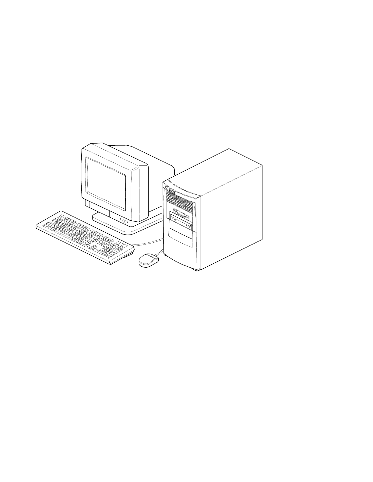
Two chassis versions are available for DIGITAL PC 3500/5510 computers: the low
profile and the short tower as shown in the following two figures. Note that your
monitor, keyboard, and mouse might look different.
Preface
xi
Page 17

Preface
Typical
xii
Low Profile
Computer
Page 18
Preface
DEC00746-2
DEC00746
Typical
Short Tower
Computer
xiii
Page 19

Preface
Audience
This guide is written specifically for anyone responsible for configuring and expanding
a DIGITAL PC 3500/5510 computer.
Organization
This guide contains the following:
Chapter 1:
•
front and rear panel com ponents, indicators , and connectors. This chapter
also explains how to physically s ec ur e y our c om puter to a desk or t able,
connect optional ext er nal dev ic es ( s uc h as headphones , microphone,
printer, etc .), use your com puter’s Windows 95 keyboar d, and create a
comfortable work ing env ir onm ent.
Chapter 2:
•
information on how to c onfigure your computer us ing the BIOS Setup utility.
Chapter 3:
•
component descriptions and locations as well as how to remove t he main
logic board, replace the battery, and upgrade to a higher-performanc e
processor.
Chapter 4:
•
install additional comput er m em or y and v ideo m em or y .
Chapter 5:
•
AGP, IS A , and PCI expansion boards.
Chapter 6:
•
install and connect opt ional m as s s torage devices.
Appendix A:
•
operating and performanc e s pec ifications. Als o inc luded is information
about your computer ’s jum per and s witch settings.
Beyond Quick Set up
Using the BIOS S etup Utility
Inside Your Computer
Main Logic Board Expansion
Adding Expansion Boards
Adding Mass Storage Dev ic es
Technical Specific ations
— This chapter describes your computer’s
—This chapter provides task-based
—This chapter pr ov ides internal computer
—This chapter ex plains how to
—This chapter ex plains how to install
—This chapter ex plains how to
—This appendix lists v ital computer
xiv
Page 20

Preface
Appendix B:
•
main logic board's memory m ap, I/O address map, interr upt map, and DMA
map.
Appendix C:
•
modes supported by your c om puter’s video circuit r y .
Conventions
Convention
Example
Quick Setup
c:\windows>
SCU.BAT
[Enter] Square brackets surrounding text r epr esent s a keyboar d key.
[Ctrl]+[Alt]+[Del] A plus sign indicates that the keys shown should be pressed
Device Mapping
Video Output I nformation
Description
Italics are typically used for titles, comm ent s, and r ef er ences
to other sections of this document or ot her docum ents.
Monospaced text indicates information that your com puter or
software displays. For example, a directory path or error
message.
Monospaced text can also indicate a command that you need
to ente r to run a n a pp lic a tion or ut ility.
at the same time.
—This appendix contains tables listing the
—This appendix describes the video
xv
Page 21

Preface
Special Notices
Three kinds of special notices are used in this
specific information.
WARNING:
cause personal injury if the hazard is not avoided.
CAUTION:
cause damage to hardware or that m ight cor r upt software.
NOTES:
indicates the presence of a hazard that can
indicates the presence of a hazard that m ight
are used to provide additional information.
System Reference
guide to emphasize
xvi
Page 22

Beyond Quick Setup
Introduction
This chapter describes your DIGITAL PC 3500/5510 computer’s front and rear panel
components, indicators, and connectors. This chapter also explains how to
physically secure your computer to a desk or table, connect optional external devices
(such as headphones, microphone, printer, etc.), use your computer’s Windows
enhanced keyboard, and create a comfortable working environment.
1
1
1-1
Page 23

Beyond Quick Setup
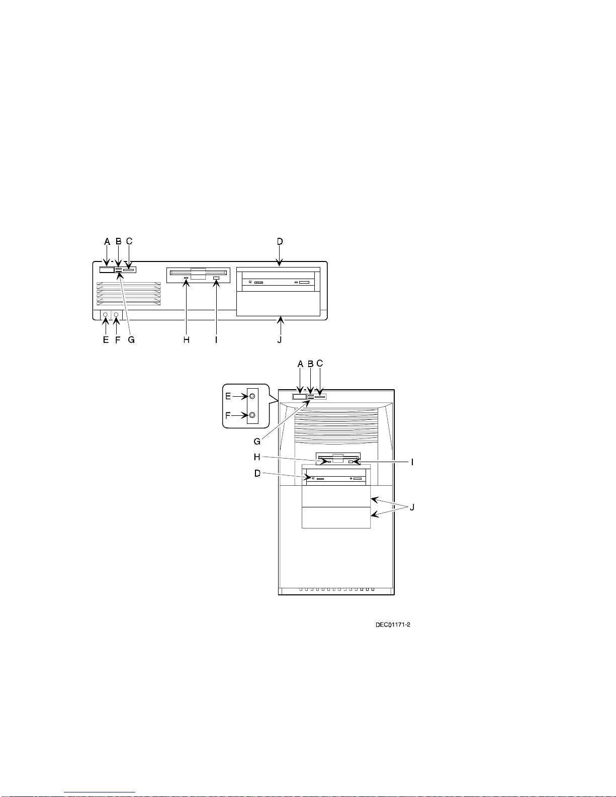
Front Panel Controls and Indicators
Figure
Control or Indicator Function
Legend
A On/off switch Turns your computer’s power on and off.
B Power LED Lights when your computer is turned on.
C Reset switch
D CD-ROM drive Not available on all models.
E Microphone jack
F Headphone jack
G Hard disk drive activity LED Lights when your hard disk drive is in use.
H Diskette activity LED Lights when the diskette drive is in use.
I Diskette eject button Releases a 3½-inch diskette from the diskette drive.
J Drive bay(s) Enables you to add additional mass storage device(s) to
(1)
DIGITAL designed the reset button so it does not protrude significantly from the front bezel. This design prevents
accidentally resetting the computer. To reset your computer, use a device such as a pen or pencil to push the
reset button.
(2)
DIGITAL PC 5510 only.
(1)
(2)
(2)
Resets your computer and causes POST to run.
This jack enables you to connect a standard microphone
to your computer.
This jack enables you to connect standard stereo
headphones to your computer.
your computer.
1-2
Page 24
Beyond Quick Setup
Figure 1-1 . Fr ont P a ne l C ontr ols a nd Indic a t or s
1-3
Page 25

Beyond Quick Setup
Rear Panel Connectors and Voltage Select Switch
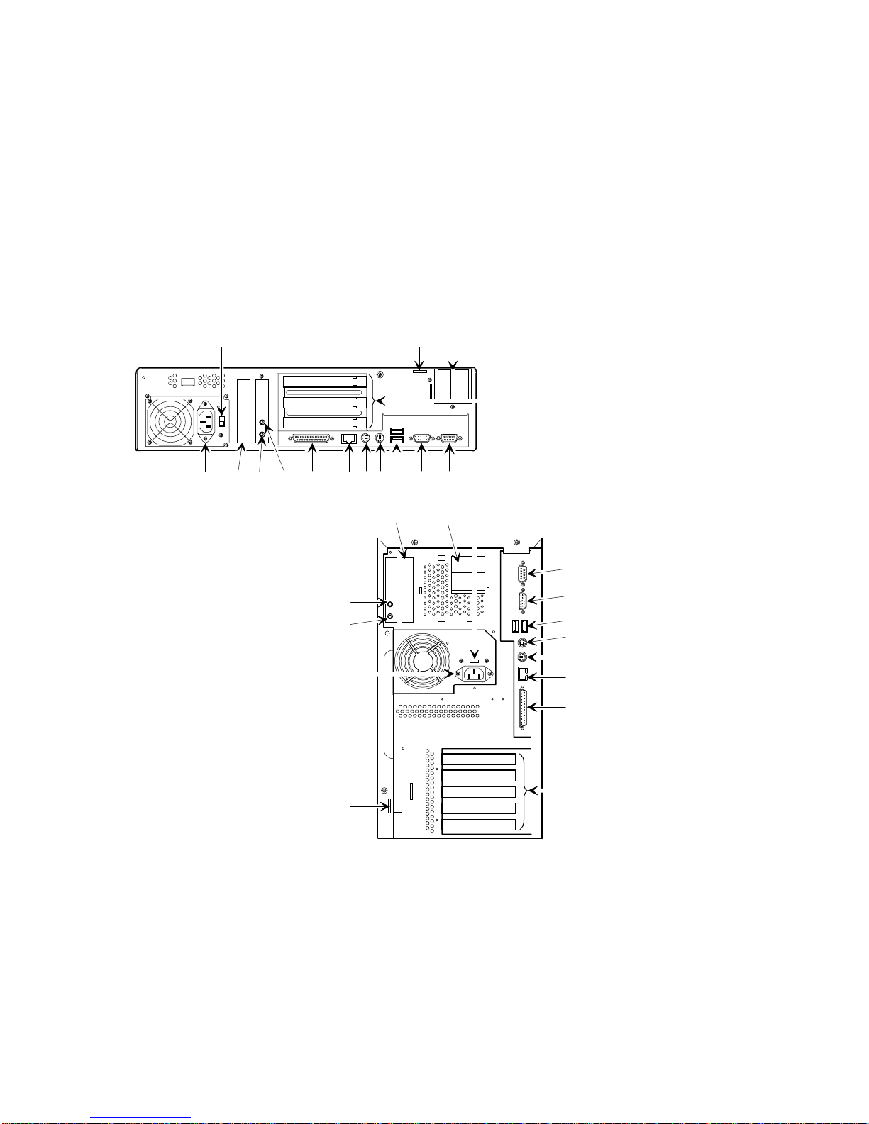
Figure
Connector or Switch Function
Legend
A Voltage select switch Enables you to select 115 V ac input power or
B Chassis lockdown Enables you to physically anchor your computer to a fixed
C AGP expansion card slot Enables you to install an Accelerated Graphics Port (AGP)
D Expansion board slots Enables you to install additional ISA and PCI expansion
E ac line connector Enables you to connect your computer to an ac power
F Feature card slot Enables you to install an optional feature card.
G Line in
H Speaker out
I Parallel port connector Enables you to connect a standard, Enhanced Parallel
J 10Base-T/100Base-TX
K Keyboard connector Enables you to connect a Windows enhanced keyboard.
L Mouse connector Enables you to connect a PS/2 style mouse.
M USB ports Enables you to connect Universal Serial Bus (USB)
N Video port (VGA connector) Enables you to connect a high-resolution monitor to your
O Serial port connector(s) Enables you to connect serial devices.
(1)
DIGITAL PC 5510 only
(1)
connector
(1)
(1)
230 V ac input power.
location.
expansion card.
boards.
source.
This jack enables you to connect an audio device to your
computer.
This jack enables you to connect a set of speakers to your
computer.
Port (EPP), or Enhanced Capabilities Port (ECP) parallel
printer.
Enables you to connect to a 10Base-T or 100Base-TX
(Twisted-Pair) network.
devices.
computer.
1-4
Page 26
Beyond Quick Setup
B
A
C
D
F
E
G
H
KJIL
N
M
O
A
CF
O
H
G
E
B
DEC01251-2
Figure 1-2 . Rear Panel Connectors and Voltage Select Switch
N
M
L
K
J
I
D
1-5
Page 27

Beyond Quick Setup
Typical CD-ROM Front Panel (not available on all
models)
Some computers come with a CD-ROM drive. For all other models, the CD-ROM
drive is a separately orderable option. The drive shown in Figure 1-3 is a typical front
panel, showing the lights, switches, and connectors on most CD-ROM drives. The
location of these items might differ depending on your CD-ROM drive.
Legend Description
A Headphone jack
B Volume controls
C CD loading tray
D Busy lamp
E Tray open/close button
F Emergency eject hole
1-6
Page 28
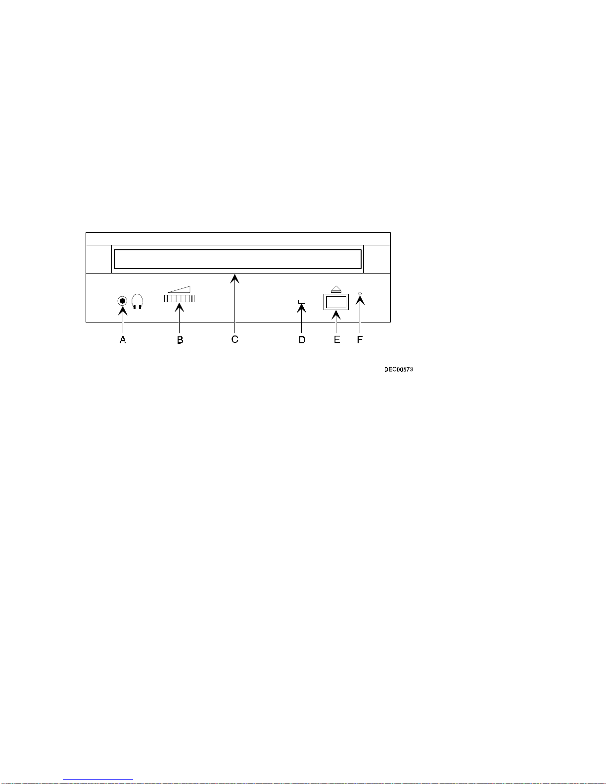
Figure 1-3 . Ty pic a l C D -R OM Fr ont P a ne l
Beyond Quick Setup
1-7
Page 29

Beyond Quick Setup
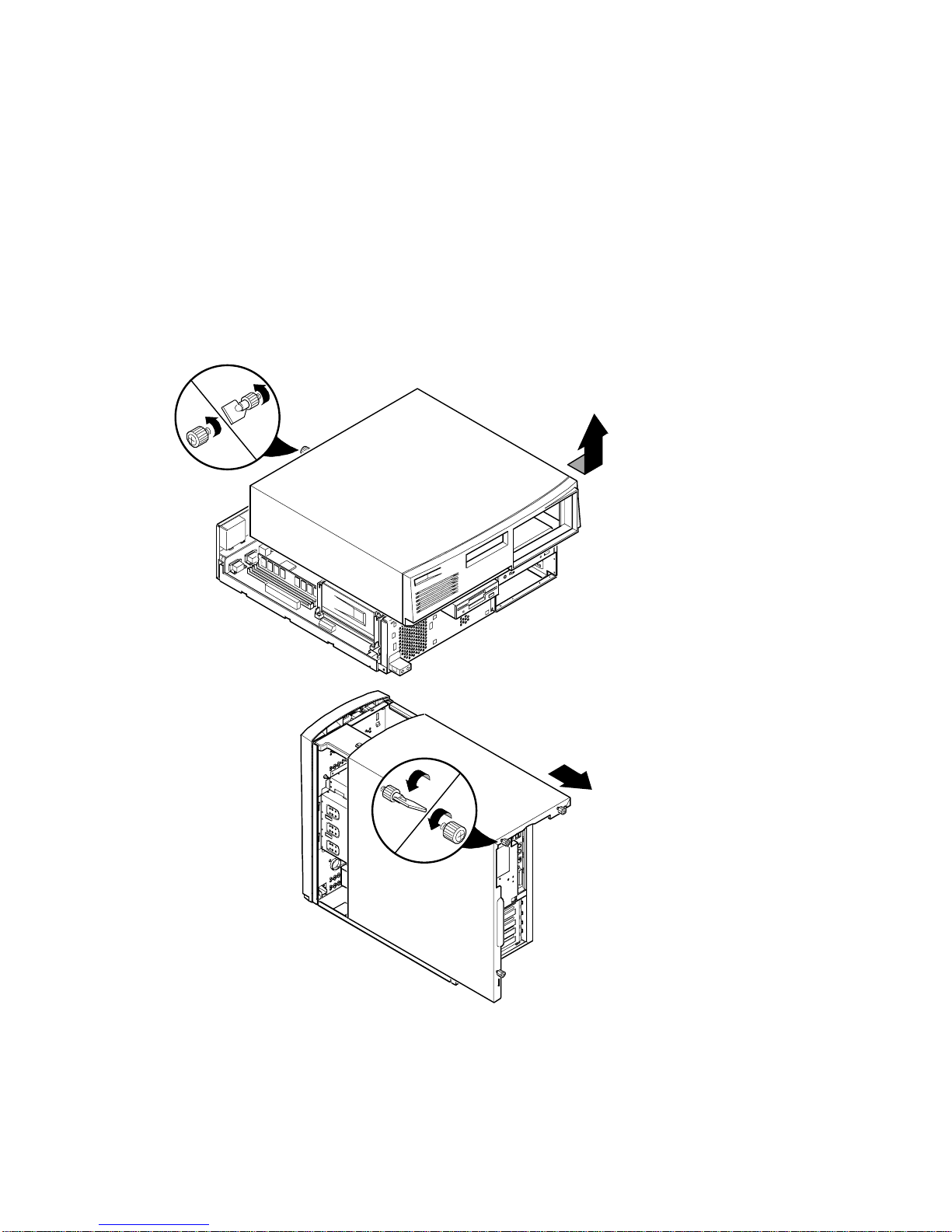
Removing your Computer’s Outside Cover
To remove your computer’s outside cover:
1. Turn off power to all external devices connected to your computer.
2. Turn your computer off.
3. Unplug your computer and monitor power cord from the wall outlet.
4. For computers without a chassis lock, go to step 4a. For computers with a
chassis lock, go to step 4b.
a. Release the outside cover by loosening the rear-panel
thumbscrew(s).
b. Unlock the outside cover by inserting the key and turning it counter
clockwise.
5. Slide the outside cover forward for the low profile and backwards for the
short tower.
6. Carefully lift the outside cover away from the chassis.
:
CAUTION
paper, cloth, or plastic. A stat ic discharge can be dam aging even
though you often cannot see or f eel it. To pr event dam age to
circuit boards and/or components:
• Before touching any circuit board or component, t ouch t he
metal frame of your com puter to discharge any static
electricity.
• Keep circuit boards and components away from nonconductors.
Static electricity collects on non-conductors such as
1-8
Page 30
Beyond Quick Setup
Figure 1-4 . Removing the Out s ide C ov e r
DEC01252-2
1-9
Page 31

Beyond Quick Setup
SecureBOX (DIGITAL PC 5510 Only)
Your computer features SecureBOX circuitry that detects the removal of the
computer cover to improve asset management of remote networked clients (see
Figure 1-5). If the computer cover is removed, SecureBOX circuitry will log the event
with system management software. SecureBOX features are implemented within
the computer hardware and BIOS design for use with ClientWORKS and/or other
system management software.
1-10
Page 32

Beyond Quick Setup
Figure 1-5 . Se c ureBOX Microswitch Location (DIGITAL PC 5510 Only)
DEC01253-2
1-11
Page 33

Beyond Quick Setup
Replacing your Computer’s Outside Cover
To replace the outside cover:
1. Replace the outside cover by sliding it onto the chassis.
2. For computers without a chassis lock, go to step 2a. For computers with a
chassis lock, go to step 2b.
a. Secure the outside cover to the chassis using the rear panel
thumbscrew(s).
b. Secure the outside cover to the chassis by inserting the key and
turning it clockwise.
1-12
Page 34

Beyond Quick Setup
Figure 1-6 . R e pla c ing the Out s ide C ov e r
DEC01252-3
1-13
Page 35

Beyond Quick Setup
Chassis Lockdown
A chassis lockdown hasp is located at the rear of your computer. It is either secured
to the outside cover or to the side of the chassis. The hasp for low profile computers
is near the top-right of the rear panel. The hasp for short tower computers is at the
lower-left of the rear panel. When locked, these hasps prevent others from opening
and removing the computer's outside cover. With the hasp in place, you can use a
chain or cable lock to secure your computer.
To secure your computer:
1. Turn off the power to all external devices connected to your computer.
2. Turn your computer off.
3. Unplug the computer power cord from the wall outlet.
4. Disconnect the power cord from your computer.
5. Remove the outside cover.
1-14
Page 36

Attaching the Hasp (Low Profile Computers)
4
To attach the hasp:
1. Pull the hasp out from the clip at the rear edge of the cover and turn it
around 180 degrees so the hasp is pointing out to the rear of the computer.
2. Insert the cover clip adjacent to the slot in the rear panel into the slots in the
rib of the hasp.
3. Slide the hasp toward you and seat the rib atop the hasp securely to the
outside cover.
4. Replace the outside cover, carefully sliding the hasp tab through the slot in
the rear panel.
5. Connect the power cord to your computer and to a wall outlet.
6. Turn on your computer and then turn on all external devices.
Beyond Quick Setup
Figure 1-7 . A tt a c hing the Hasp (Low Prof ile C om puters)
DEC0117
1-15
Page 37

Beyond Quick Setup
Attaching the Hasp (Short Tower Computers)
To attach the hasp:
1. Insert the hasp tab, with the lock/cable hole, through the slot in the rear
panel.
2. Slide the foot of the hasp behind the rear panel tongue and seat the foot
securely.
3. Replace the outside cover, carefully sliding the left, rear-edge slot over the
hasp.
4. Connect the power cord to your computer and to the wall outlet.
5. Turn on your computer and then turn on all external devices.
Figure 1-8 . A tt a c hing the Hasp (Short Tower Computers)
1-16
DEC00881
Page 38
Beyond Quick Setup
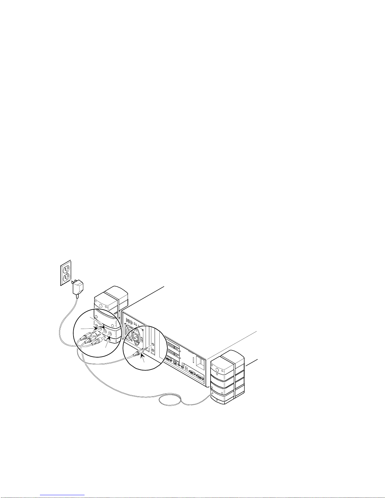
Connecting Speakers (DIGITAL PC 5510 Only)
If your computer came with integrated audio capabilities and you purchased
speakers, perform the following instructions to connect them:
1. Unpack the speakers.
2. Plug the slave speaker cable into the master speaker “Speaker Output”
(A, Figure 1-9 or 1-10).
3. Connect the other cable to the master speaker “Audio Input” (B, Figure 1-9
or 1-10) and to the adapter card “Speaker Out” (C, Figure 1-9 or 1-10).
4. Connect the ac-to-dc adapter cord to the master speaker (D, Figure 1-9 or 1-
10).
5. Plug the speaker ac-to-dc adapter into a power outlet.
A
B
D
Figure 1-9 . C onne c ting S peakers (Low Pr ofile C om put ers)
C
DEC01175
1-17
Page 39

Beyond Quick Setup
C
A
D
B
Figure 1-1 0 . C onne c ting S peakers (Short Tower Computers)
1-18
DEC01254-2
Page 40

Beyond Quick Setup
Connecting Headphones (DIGITAL PC 5510 Only)
If your computer came with integrated audio capabilities and you purchased
headphones, perform the following instructions to connect them:
1. Unpack the headphones.
2. Connect the headphones cable into the connector at the left/front of yo u r
computer.
Figure 1-1 1 . C onne c ting H e a dphone s
DEC00897-2
1-19
Page 41

Beyond Quick Setup
Connecting a Microphone (DIGITAL PC 5510 Only)
If your computer came with integrated audio capabilities and you purchased a
microphone, perform the following instructions to connect it:
1. Unpack the microphone and assemble the base.
2. Connect the microphone cable into the connector at the left/front of your
computer.
1-20
Page 42

Beyond Quick Setup
Figure 1-1 2 . C onne c ting a M ic r ophone
DEC00897-3
1-21
Page 43

Beyond Quick Setup
Connecting a Local Printer
Perform the following steps to connect a local printer to your computer:
1. Look over your printer documentation and perform any pre-installation
instructions before attempting to connect it to your computer.
2. Make sure your printer and computer are turned off.
3. Plug the printer cable into the appropriate printer port (the parallel port for a
parallel printer and a serial port for a serial printer).
4. Turn your computer and printer on.
5. Configure your printer for operation with your computer.
Refer to your Windows 95 or Windows NT Workstation on-line help and printed
documentation for instructions on installing your printer’s device driver.
1-22
Page 44

Beyond Quick Setup
Figure 1-1 3 . C onne c ting a Loc a l P r inte r
DEC01177-3
1-23
Page 45

Beyond Quick Setup
Connecting a Universal Serial Bus (USB) Device
USB simplifies connectivity requirements for plug and play external devices by
consolidating ports and eliminating the need to open the computer to plug in
expansion boards.
If you purchased a USB device for your computer, perform the following instructions
to connect it:
1. Unpack the USB device.
2. Connect the USB device cable into one of the USB port connectors at the
rear of your computer.
Refer to your manufacturer’s documentation for installation instructions.
1-24
Page 46

Beyond Quick Setup
Figure 1-1 4 . C onne c ting a U S B Device
DEC01255-2
1-25
Page 47

Beyond Quick Setup
Your Computer’s Windows Enhanced Keyboard
Your computer comes equipped with a 104-key Windows enhanced keyboard that
enables you to communicate with your computer by entering data or commands.
The right and left Windows keys (A and B, Figure 1-15) bring up the Start menu
much like pointing and clicking the left mouse button on the Start button. These keys
can be used at any time you are in the Windows shell and do not affect or change the
current mouse position. Both keys can be used to modify other keys. The operating
system controls the functionality of the Windows keys and only shell applications
should implement these keys.
AB
Figure 1-1 5 . Windows Enha nc e d Keyboard
1-26
DEC00986-2
Page 48

Beyond Quick Setup
Creating a Comfortable Working Environment
Under circumstances of poor posture or poor setup, certain recent scientific articles
suggest that injuries may occur. Other articles suggest that there is no cause and
effect. Because the safety of our users is a great concern, it is important to take
these precautions:
Be comfortable in your work space.
•
Change your posture frequently.
•
Proceed according to the recommendations in the following table and figure.
•
Adjust So . . .
Chair Feet are flat on the floor.
Legs are vertical forming a right angle to the floor.
Your weight is off your thighs and they are horizontal. Keep the back
of your knees away from the seat so you do not compress the area
behind them, which could restrict the blood flow.
Your upper body is erect and your lower back is supported with a
backrest.
Keyboard or mouse Your wrists are straight and do not bend more than 15 degrees. They
Head Avoid neck strain. Your head should incline downward, but no more
may be supported when resting but not on sharp edges. Type
comfortably, with no more key pressure than needed to feel the
contact point.
Upper arms are straight down at your sides, elbows are close to your
sides and support your arm weight. Forearms are at a 70 degree to 90
degree angle.
If you use a mouse, rest your hand on the mouse so your wrist is not
on the work surface. Operate the mouse close to your body’s
centerline.
than 15 to 20 degrees.
1-27
Page 49

Beyond Quick Setup
Adjust So . . .
Monitor No higher than the level of your eyes and at the correct distance for
Work breaks Take periodic work breaks. Morning, lunch, and afternoon breaks
Lighting Avoid direct lighting or sunlight on the screen, which causes glare and
Noise Keep background noise at a minimum. Background noise above 65
Temperature 20 to 23 degrees C (68 to 74 degrees F).
Humidity 30% to 70%.
Ventilation Provide adequate air ventilation to avoid fatigue and to operate the
Space between set ups > 70 cm (28 in.) center to center, preferably
your vision.
Avoid eye fatigue, which can be caused by glare, image quality,
uncomfortable furniture, eye height, and uncorrected vision. If you
cannot focus to read at different distances, you may need special
glasses. Relax your eyes periodically by looking at distant objects.
during the 8-hour workday meet most recommendations. Take
advantage of work breaks to move around and do other activities.
reflections. Place lighting behind or to the side of your work area, and
distribute the lighting evenly on your work area.
Your computer monitor’s screen has an antiglare treatment to reduce
glare. Adjust the brightness and contrast controls as needed.
dBA is tiring. Sound-absorbing materials (curtains, carpeting, and
acoustic tile) can help reduce background noise.
equipment.
> 152 cm (60 in.).
1-28
Page 50

Beyond Quick Setup
IMPORTANT: I f you experience pain or discomfort during use
of the PC, take a rest break and r eview the instr uct ions f or
proper ergonomic setup and use. If the pain or discomfort
continues after resuming use of t he PC, discontinue use and
report the condition to your job supervisor or physician.
Figure 1-1 6 . Creating a C om f or ta ble Wor k ing E nv ir onm e nt
DEC00454
1-29
Page 51

Using the BIOS Setup Utility
What is the BIOS Setup Utility?
The BIOS Setup utility enables you to select and store information about your
computer's hardware and software permanently in the battery-backed memory of the
CMOS RAM. This information takes effect each time the computer boots and can be
changed any time you run setup.
You should use the BIOS Setup utility if you experience problems with your hard disk
or if you need to reconfigure or expand your computer.
This chapter provides information on how to configure your computer using the BIOS
Setup utility.
:
CAUTION
factory and will operate properly without addit ional conf iguring.
It is important f or you to read carefully and understand this
chapter before att em pt ing t o m odif y your com put er 's factory
settings. Changing some settings might cause your com put er t o
operate improperly.
Here are some instances when you might wish to change your computer’s initial
setup. You might need to:
Your computer was setup for nor m al operation at the
2
2
Change time and date
•
Alter your computer’s security level
•
2-1
Page 52

Using the BIOS Setup Utility
Change the boot options
•
Reconfigure power management
•
Setup your keyboard for your comfort and use
•
Additionally, you might need to change your computer’s initial setup after:
Upgrading hardware (such as adding a new hard drive)
•
Reconfiguring your mouse, COM, or LPT port
•
:
NOTE
record the new settings and keep this informat ion in a safe
place. Should you ever have to reset the settings, such as
when you replace your battery, you can use t his infor m at ion t o
reconfigure your computer ’s BIOS.
If you do change BIOS settings, m ake sur e you
The remainder of this chapter explains how to run the BIOS Setup utility, maneuver
through the options, and perform specific tasks.
Accessing the BIOS Setup Utility
To access the BIOS Setup utility, perform the following steps:
1. Turn on your computer and allow the Power-On Self Test (POST) to run.
2. Make a note of any configuration errors listed, and then press [F2], when
displayed, to access the Main menu.
3. Follow the instructions on your monitor screen and any on-line help pop-up
screens to configure you computer.
2-2
Page 53

Helpful Hints
When using the BIOS Setup utility consider:
Several keyboard keys are assigned to help you select menus and sub-
•
menus, options, change option values, and display help information. These
keys are displayed at the bottom of all menus, and are listed in the following
table.
Key Function
F1 Help (provides a general help screen)
Esc Exit (Exits the Setup utility and exits sub menus within the Setup utility)
arrow keys Select Item
↑↓
arrow keys Sel ect Menu
← →
-/+ or spacebar Change Values
Enter Select > Sub-Menu
F9 Setup Defaults (Sets all Setup options to factory default values)
F10 Previous Values (Restores all BIOS values from the last session)
Item-specific help is available anytime during the setup process and appears
•
at the right of the setup screen when an option is highlighted.
Using the BIOS Setup Utility
2-3
Page 54

Using the BIOS Setup Utility
Choosing the “
•
−
−
−
−
−
” menu reveals several helpful options:
Exit
Select “
Exit Saving Changes
Setup.
Select “
Select “
Discarding
:
NOTE
Answer the Warning message carefully.
Load Setup Defaults
factory default values.
Select “
Discard Changes
last session.
Select “
Save Changes
Setup.
” to save all Setup values and exit
” to exit Setup without recording any changes.
” to set all setup options to their
” to restore all setup values from the
” to save all setup selections without exiting
2-4
Page 55

Using the BIOS Setup Utility
Changing Your Computer’s Configuration
The following sections provide detailed information on changing your computer’s
factory configuration. Before changing any setting, make sure you fully read and
understand the information provided and view any on-line help for a selected setting.
Changing Time and Date
There may be instances when it will be necessary to change the date and/or time
that is resident in your computer’s BIOS. The following directions show you how this
is done.
1. Reboot the computer and enter Setup.
2. In the Main menu, using the cursor keys and [Tab], select (highlight) the
System Time or System Date field you want to change.
3. Use [+] or [-] to change the field to the desired value.
You can also enter the desired date and time.
4. Save Changes and Exit Setup and allow your computer to reboot.
:
NOTE
operating system.
The date and time can also be set from within the
Setting Up Security
Computer security is important to prevent theft or accidental loss of your computer
software and data. The following sections describe the BIOS security features
available and how to use them.
2-5
Page 56

Using the BIOS Setup Utility
Setting Supervisor and User Passwords
Your computer has two password levels that can be set to prevent unauthorized
access to computer files or to the BIOS Setup utility. If a supervisor password is set,
the computer asks you to enter a password before accessing the BIOS Setup utility.
In order to use the password features, “Password On Boot” must be enabled.
If "Password On Boot" is enabled, and both the supervisor and user passwords are
enabled, you need to enter either the supervisor or user password to use the
computer. “Password On Boot” limits who accesses the computer and the level of
functionality you receive.
Additionally, if after selecting [F2] during the boot sequence, the user password is
entered instead of the supervisor password, the Main, Advanced, Boot, and Power
menus in the BIOS Setup utility are rendered inaccessible.
:
NOTE
user password. If the super visor password is later deleted, t he
user password is automatically removed.
Perform the following steps to set a supervisor password:
1. Reboot the computer and enter Setup.
2. Highlight the “Security” menu.
A supervisor password must be set before you can set a
3. Highlight “Set Supervisor Password” and press [Enter].
4. Type in a seven (7) digit alpha-numeric supervisor password and then press
[Enter].
5. Retype your password as instructed and press [Enter]. (Notice that
“Supervisor Password Is” field now indicates Enabled.)
2-6
Page 57

Using the BIOS Setup Utility
If desired, set a user password as follows:
1. Highlight “Set User Password” and press [Enter].
2. Type in a seven (7) digit alpha-numeric user password and then press
[Enter].
3. To confirm, retype your user password as instructed and press [Enter].
(Notice that “User Password Is” field now indicates Enabled.)
4. Press [Esc] then [Enter] twice to exit the BIOS Setup utility and to reboot the
computer so changes immediately take affect.
The computer runs the POST and then asks for the password, which has
just been set.
If you forget your password, refer to Appendix A “Technical Specifications” for information
on resetting your password.
Enabling Password On Boot
When “Password On Boot” is enabled, a screen appears after POST. The screen
asks you to enter your supervisor password or user password to allow your computer
to finish the boot sequence.
Perform the following steps to set “Password On Boot”:
1. Reboot the computer and enter Setup.
2. Highlight the “Security” menu.
3. Highlight “Password On Boot.”
4. Press the [+] key to set to Enabled. (Pressing the [+] key again reverses
your action.)
5. Press [Esc] then [Enter] twice to exit the BIOS Setup utility and to reboot the
computer so changes immediately take affect.
The computer runs the POST and then asks for the password.
2-7
Page 58

Using the BIOS Setup Utility
Eliminating User and Supervisor Passwords
To eliminate your computer’s password(s), follow the directions given below:
1. Reboot the computer and enter Setup.
2. Enter the supervisor password and press [Enter].
3. Do you wish to eliminate the User Password or the Supervisor Password?
4. If User Password, select “Set User Password.”
If Supervisor Password, select “Set Supervisor Password.”
5. Press Enter three times.
6. You have cleared the old password and are returned to the “Security” menu.
Verify that the appropriate password is disabled by checking “User
Password is” or the “Supervisor Password is” field, whichever is relevant.
7. Press [Esc] then [Enter] twice to exit the BIOS Setup utility and to reboot the
computer so changes immediately take affect.
Protecting Against Boot Sector Viruses
Your computer incorporates, in the BIOS Setup utility, a selection to protect the BIOS
from attacks by viruses. SecureBIOS is described below.
2-8
Page 59

Using the BIOS Setup Utility
SecureBIOS
Your computer offers improved security features that protect against unauthorized
flash BIOS firmware changes. SecureBIOS features are implemented within the
computer hardware and BIOS design for use with ClientWORKS and/or other
computer software. This feature is enabled by default.
:
NOTE
Follow the st e ps b e low to do this, using the BIOS Setup u tility.
Next time you reboot the computer, t he Sec ur eBIOS feature will
automatically reset to “ enabled.”
To disable the SecureBIOS feature:
1. Turn off your computer and remove the outside cover.
2. Locate the switch settings on the main logic board.
Refer to Appendix A, “Technical Specifications,” for main logic board switch locations.
Change switch SW1-5 to ON.
3.
Replace the outside cover.
4.
Reboot the computer and enter Setup.
5.
Before flashing the BIOS, you must disable SecureBIO S.
Highlight the “Main” menu.
6.
7. Highlight “Boot Options” and press [Enter].
8. Highlight “BIOS Update.”
9. Press the [+] key to enable “BIOS Update” (pressing the [+] key again,
returns your computer to normal).
10. Press [Esc] twice, then [Enter] twice to save and to reboot the computer so
changes immediately take affect.
:
NOTE
SW1-5 be reset to OFF t o pr ovide additional prot ect ion against
BIOS corruption or viruses.
After flashing the BIOS, it is recom m ended t hat switch
2-9
Page 60

Using the BIOS Setup Utility
Other Security Options
These options can provide further security for your computer under certain
conditions.
If “Password On Boot” is enabled and “Diskette Access” is set to
•
“Supervisor,” entering the supervisor password at boot allows access to a
diskette. Entering the user password at boot, however, prevents the
computer from accessing a diskette.
:
CAUTION
“Password on Boot” option. While this option is enabled, the
contents of the hard disk drive cannot be backed up t o disket t es
and the computer cannot be boot ed f r om a disket t e dr ive.
Consider your security needs before using the
•
Diskette Access
− This option works in conjunction with the “Password on
Boot” setting and can be set to prevent information on the computer’s hard
disk drive from being copied to a diskette.
When this option is set to “User” and “Password on Boot” is disabled, all
users can copy to and from a diskette. When this option is set to
“Supervisor” and “Password on Boot” is disabled, no one can copy to and
from a diskette.
When the “Password on Boot” option is enabled and “Diskette Access” is set
to “User”, all users can copy to and from a diskette. When this option is set
to “Supervisor” and “Password on Boot” is enabled, users who log on with a
user password cannot copy to and from a diskette; users who log on with a
supervisor password can copy to and from a diskette.
•
Custom Sign On Banner
− When enabled, allows a custom banner to be
displayed every time you turn your computer on.
2-10
Page 61

Using the BIOS Setup Utility
Remote Network Wake-up (DIGITAL PC 5510 Only)
Your computer features remote network wake-up technology that allows easy system
management of networked client computers, even if the system power switch is
turned off.
Utilizing Magic Packet software, developed by AMD, the system hardware design
provides standby power to the integrated network interface controller. The controller
can then power on the system when it receives an authorized network wake-up
signal.
Additional system security is provided by a SecureON feature that provides greater
system protection against unauthorized network intrusion. The system BIOS settings
enable either wake-up modes or allow bypass of client password protection by the
system administrator.
To set the Remote Network Wake-up feature:
1. Reboot the computer and enter Setup.
2. Highlight the “Advanced” menu.
3. Highlight “Integrated Network Controller.”
4. Press the [+] key to set to Enabled, if necessary.
5. Highlight “Remote Network Wake-Up.”
6. Press the [+] key to one of the available options.
7. Press [Esc] twice then [Enter] twice to exit the BIOS Setup utility and to
reboot the computer so changes immediately take effect.
:
NOTE
“Magic Packet” provides basic wake-up capabilit ies allowing t he syst em t o
be powered up remotely. Selecting “SecureON” increases security by
requiring a password for access to the network.
For more information, refer to your ClientWORKS and/or System Software
documentation.
This setting defaults to “Disabled.” Changing the f eat ure to
2-11
Page 62

Using the BIOS Setup Utility
Setting Power Management Options
This section describes how to select and set your computer’s Power Management
parameters using the BIOS Setup utility.
:
NOTE
your computer’s power management features (Windows 95 only).
Windows NT Workstation does not support power management .
Your computer’s BIOS has power managem ent features but
Windows NT Workstation does not support them.
Setting up Power Management
NOTE
BIOS Setup utilit y apply unles s t he “ Power Savings” field is
Enabled.
To initialize the power management features:
1. Reboot the computer and enter Setup.
You can use DIGITAL’s Power M anagem ent utility to set
:
None of the power management f eat ur es available in the
2. Highlight the “Power” menu.
3. Highlight “Power Savings.”
2-12
Page 63

Using the BIOS Setup Utility
4. Press the [+] key to select one of the available options.
:
NOTE
have been preset. You can change these times by selecting them
and pressing the + key to sequence through the available options.
In “Standby” mode, per ipher al component s are put in their lowest
active states in addition to reducing the processor speed af t er t he
set period of inactivity.
In “Suspend” mode, peripher al component s ar e shut off, and the
CPU speed is further reduced after t he set per iod of inact ivity.
Choose other Power Savings options as desired.
5.
Press [Esc] then [Enter] twice to exit the BIOS Setup utility and to reboot the
6.
“Auto Standby Timeout” and “Aut o Suspend Timeout ”
computer so changes immediately take affect.
2-13
Page 64

Using the BIOS Setup Utility
Configuring for New Disk Drives
These sections describe how to configure new disk drives in the BIOS Setup utility.
Diskette Drive Configuration
Diskette drives need to be configured from within the BIOS Setup utility once the new
diskette drive is installed.
To configure a newly installed diskette drive, proceed as follows:
1. Reboot the computer and enter Setup.
2. Highlight the Main menu.
3. Highlight “Diskette A” or “Diskette B” (depending upon how you connected
the diskette drive to your computer).
4. Press the [+] key to sequence through the available options.
5. Press [Esc] then [Enter] twice to exit the BIOS Setup utility and to reboot the
computer so changes immediately take affect.
2-14
Page 65

Using the BIOS Setup Utility
Hard Disk Drive Configuration
Installing new ANSI-supported IDE hard disks is made easier by the “Autotype” drive
detect mode available in the BIOS Setup utility. Operating systems such as
Windows NT which are not Plug and Play capable might require you to use the
“Autotype” feature.
Autotyping a Hard Disk
To Autotype a newly installed hard disk:
1. Reboot the computer and enter Setup.
2. Highlight the “Main” menu.
3. Select an “IDE Adapter” field to assign the new hard disk and press [Enter].
4. Select “Autotype Fixed Disk” and press [Enter].
The BIOS Setup utility searches the hard disk and fills-in the disk
parameters. If a parameter does not read correctly, follow the “Manually
Defining a Hard Disk” procedure given later in this chapter.
5. Press [Esc] once and verify that the selected IDE Adapter field reads
correctly for your hard disk.
For example: IDE Adapter 0 Master (C: 835 MB). If the selected IDE
Adapter field does not read correctly, follow the “Manually Defining a Hard
Disk” procedure given later in this chapter.
6. Press [Esc] once then [Enter] twice to exit the BIOS Setup utility and to
reboot the computer so changes immediately take affect. The new hard disk
drive will be detected and the “type” field will be set to “Auto.”
2-15
Page 66

Using the BIOS Setup Utility
Manually Defining a Har d Disk
If your hard disk was not recognized correctly by the Autotype mode in the BIOS
Setup utility, or you wish to change your hard disk’s definition, you can manually
define your hard disk drive as follows:
1. Reboot the computer and enter Setup.
2. Highlight the “Main” menu.
3. Select an “IDE Adapter” field to assign the new hard disk and press [Enter].
4. Fill-in the parameters of the hard disk in the appropriate fields.
5. Press [Esc] once and verify that the selected IDE Adapter field reads
correctly for your hard disk. For example: IDE Adapter 0 Master
(C: 835 MB).
6. Press [Esc], then [Enter] twice to exit the BIOS Setup utility and to reboot the
computer so changes immediately take affect.
2-16
Page 67

Using the BIOS Setup Utility
Changing the Boot Priority
It is sometimes necessary to change your computer’s boot sequence. For example,
when you need to boot from a diskette or CD-ROM.
To change the boot priority, proceed as follows:
1. Reboot the computer and enter Setup.
2. Highlight the “Boot” menu.
3. Highlight “Boot Device Priority” and press [Enter].
Diskette drive, Hard Disk, and CD-ROM Drive are displayed. The number
shows the current ordering. For example, if CD-ROM Drive is 1 and
Diskette Drive is 2, the computer boots first from the CD-ROM drive. If it is
empty, the computer goes to the diskette drive and then finally to the hard
disk drive.
4. Use the [↑] and [↓] arrows to locate the field you want to change. Then use
the [+] to raise the order and [-] to lower it.
5. Press [Esc] twice then [Enter] twice to exit the BIOS Setup utility and to
reboot the computer so changes immediately take affect.
:
NOTE
to display the Boot menu. Select a device from the list as t he
bootable device. You can also enter the BIOS Setup utility from
this menu.
To override this BIOS setting, press [Esc] during POST
When changing the boot priority, be aware of the following:
Some CD-ROM drives do not auto-type correctly. This will be apparent during
•
POST, when the CD-ROM identified message is not displayed. In this case,
enter BIOS Setup and manually select the hard disk type for the CD-ROM,
instead of allowing Setup to auto-type it.
2-17
Page 68

Using the BIOS Setup Utility
Changing the Hard Drive Sequence
If your computer has multiple hard disk drives installed, it might become necessary to
change the hard drive boot sequence. For example, when you have more than one
operating system installed.
To change the hard drive boot sequence, proceed as follows:
1. Reboot the computer and enter Setup.
2. Highlight the “Boot” menu.
3. Highlight “Hard Drive” and press [Enter].
The installed hard drive devices are displayed. The number shows the
current order that the hard drives are installed during computer boot.
4. Use the [↑] and [↓] arrows to locate the field you want to change. Then use
the [+] to raise the order and [-] to lower it.
5. Press [Esc] twice then [Enter] twice to exit the BIOS Setup utility and to
reboot the computer so changes immediately take affect.
When changing the hard drive boot sequence, be aware of the following:
Many advanced operating systems, such as Windows 95, Windows NT, OS/2
•
Warp, Unix, and others, modify the boot sector of any hard disk drives that are
installed in the computer, while the operating system is being installed. This can
cause normally bootable hard disk drives to be rendered non-bootable, even
though the user did not want this behavior.
In systems where there are two or more bootable hard disk drives, it is
recommended that all bootable hard disk drives, other than the target of the new
operating system, be removed from the computer before installing the new
operating system.
Once installation of the new operating system is complete, the other hard disk
drives can then be reinstalled. This simple procedure prevents the operating
system from modifying the boot sectors of the other bootable drives, thus
preserving the capability of choosing one of several hard disk drives from which
to boot.
2-18
Page 69

Using the BIOS Setup Utility
Speeding up the Boot Process
There are several options for speeding up the boot process. They in essence
eliminate or replace displays or checks. To make these changes, proceed as follows:
1. Reboot the computer and enter Setup.
2. Highlight the “Boot” menu.
The following table lists the relevant items displayed and describes them.
Field Description
Summary screen Displays the computers configuration.
Floppy check Verifies the floppy boot drive.
2-19
Page 70

Using the BIOS Setup Utility
3. Select the item(s) you wish to change and use the [+] or [-] as follows:
Field Speed Up Boot Selection
Summary Disable
Floppy check Disable
4. Press [Esc] twice then [Enter] twice to exit the BIOS Setup utility and to
reboot the computer so changes immediately take effect.
Resetting Keyboard Features
Several parameters effecting keyboard performance can be altered from within the
BIOS Setup utility. They are: “NumLock,” “Key Click,” “Keyboard Auto-Repeat
Rate,”and “Keyboard Auto-Repeat Delay.”
“NumLock” is factory set to “Auto” at boot which means that the number pad
•
is on each time you boot. This is desirable, for example, if you primarily use
spreadsheets or accounting software.
If, however, you primarily use a word processor or desktop publishing
program, you might wish to leave NumLock off at boot to avoid having to
turn it off manually.
“Key Click,” when enabled, produces an audible “Click” whenever a key is
•
pressed.
“Keyboard Auto-Repeat Rate” sets the number of times per second a
•
character repeats.
Most keys on the keyboard automatically repeat the character they
•
represent if the keys are held down.
“Keyboard Auto-Repeat Delay” sets the time that elapses before the
•
character begins repeating.
2-20
Page 71

Using the BIOS Setup Utility
Changing the Keyboard Features
To change the keyboard features:
1. Reboot the computer and enter Setup.
2. Highlight the “Main” menu.
3. Highlight “Keyboard Features” and press [Enter].
If you wish to leave “NumLock” on, skip steps 4 and 5, otherwise:
4. Highlight “NumLock.”
5. Press the [+] key to sequence through your options, select “Off.”
If you wish to leave “Key Click” disabled, skip steps 6 and 7, otherwise:
Select “Key Click.”
6.
7. Press the [+] key to select Enable.
If you wish to leave the “Keyboard Auto-Repeat Rate” (the number of times per
second a character repeats) the same, skip steps 8 and 9, otherwise:
Highlight “Keyboard Auto-Repeat Rate.”
8.
9. Press the [+] key to sequence through the available options.
If you wish to leave the “Keyboard Auto-Repeat Delay” (the time that elapses before
the character begins repeating) the same, skip steps 10 and 11, otherwise:
10. Highlight “Keyboard Auto-Repeat Delay.”
11. Press the [+] key to sequence through the available options.
12. Press [Esc] twice then [Enter] twice to exit the BIOS Setup utility and to
reboot the computer so changes immediately take effect.
2-21
Page 72

Using the BIOS Setup Utility
Flash Utilit y
All computers have BIOS software in a read-only, non-volatile memory (ROM) chip.
This BIOS initializes hardware and boots the operating system when the computer is
turned on. The BIOS also provides access to other services such as keyboard and
disk drives.
Your computer comes equipped with flash memory. This means that you can restore
your computer’s BIOS simply by running the flash utility. If necessary, you can also
upgrade your computer’s BIOS to future releases by running the flash utility along
with any flash BIOS update diskette.
Only use the flash utility to upgrade your computer’s BIOS if you are instructed to do
so by an a u th o r i ze d D IGITA L support representative. You can download BIOS
updates along with the flash utility and instructions on how to flash your computer’s
BIOS from DIGITA L ’ s web site:
www.windows.digital.com.
Refer to the “Preface” for additional access information.
2-22
Page 73

Inside Your Computer
Introduction
This chapter shows the location of your computer’s internal components. Expansion
information is also covered in this chapter along with illustrations detailing the:
Main logic board
•
Backplanes
•
Each computer contains a main logic board and a backplane. The main logic board
provides most of the chips and components. The backplane contains slots for
connecting expansion boards.
The chapter concludes with instructions on how to:
Remove the main logic board
•
Replace the battery
•
Install a higher-performance processor
•
Install a Voltage Regulator Module (VRM)
•
3
3
Install optional feature cards
•
3-1
Page 74

Inside Your Computer
Improving Computer Performance
As your computing needs change, you can achieve improved computer performance
by:
Installing additional computer memory
•
Adding a higher-performance video controller and/or more video memory
•
Upgrading your hard disk drives
•
Installing a higher performance main logic board design
•
Preparing Your Computer for Expansion
Before you begin to expand your computer, refer to Chapter 1, “Beyond Quick
Setup,” for instructions on preventing component damage from static electricity,
disconnecting external devices, and removing the outside cover.
Your Computer’s Components and Connectors
The following sections show your computer’s main logic board, backplane, and
adapter card component and connector locations. Use the information presented
anytime you need to connect external devices, expand, or upgrade your computer.
Computer Components
Figure
Legend
A Internal 3½-inch drive bay(s)
B Power supply
C Front access 5¼-inch drive bay with CD-ROM (not available on all models)
D Front access 5¼-inch drive bay(s)
E 3½- inch diskette drive
F Backplane
G Main Logic Board (MLB)
3-2
Component
Page 75

Inside Your Computer
A
B
C
D
G
G
F
E
E
C
D
Figure 3-1 . C om pute r C om pone nt s
B
A
F
DEC01253-3
3-3
Page 76

Inside Your Computer
Main Logic Board Components
Figure
Component
Legend
A Video controller
B Onboard video memory
C Ethernet controller
D PCI/ISA/IDE Xcellerator (PIIX4)
E System and video FLASH BIOS
F Peripheral input/output controller
G Computer battery
H Voltage Regulator Module (VRM)
I Pentium II processor
J Dip switch
K Intel 440LX chip
(1)
Not available on all models
(1)
3-4
Page 77

Inside Your Computer
E
C
D
F
B
G
H
A
I
K
J
DEC01256-2
Figure 3-2 . Ma in Logic B oa r d C om pone nt s
3-5
Page 78

Inside Your Computer
Rear Panel Connectors
Figure
Connector
Legend
A Parallel port
B 10/100BaseTX network port
C Keyboard port
D Mouse port
E Two USB ports
F Video (VGA) port
G Serial port
H AGP video port (located on rear chassis)
(1)
Not available on all models
(1)
A
B
C
D
E
F
G
H
Figure 3-3 . Rear Panel Connectors
3-6
DEC01256-3
Page 79

Main Logic Board Connectors
Inside Your Computer
Figure
Connector
Legend
A Three 168-pin, DIMM, 64-bit SDRAM sockets
B Video memory (SGRAM) upgrade connectors
C AUI/BNC (network) connector
D AGP graphics expansion board connector
(1)
DIGITAL PC 5510 only
(1)
C
B
A
Figure 3-4 . Ma in Logic B oa r d C onne c t or s
D
DEC01256-4
3-7
Page 80

Inside Your Computer
Low Profile Backplane Components and Connectors
Figure
Connector
Legend
A PCI expansion board connectors
B ISA expansion board connectors
C Primary IDE drive connector
D Secondary IDE drive connector (recommended for an installed CD-
E Diskette drive connector
F Audio rear panel connector
G CD-ROM audio input connector (CD-IN)
H Fax/modem audio input connector (F/M IN)
I Control panel connector
J Fan connector (user option)
K Crystal CS4236B audio controller
L SCSI LED connector
M Micro switch connector
N Main logic board connectors
O Power connector
(1)
This connector is used for Fax/Modems with speaker phone capabilities.
(2)
DIGITAL PC 5510 only
ROM drive)
(2)
(2)
(1)
(2)
(2)
3-8
Page 81

Low Profile Fax /M ode m A udio Input C onne c t or (F/M IN )
Item H, Figure 3-5 Description
Pin 1 Audio in (fax/modem)
Pin 2 Ground
Pin 3 Ground
Pin 4 Microphone in (fax/modem)
(1)
DIGITAL PC 5510 only.
(1)
CD
E
Inside Your Computer
H
1 2 3 4
B
A
N
O
M
L
Figure 3-5 . Low Pr of ile Backplane Components and Conne c t or s
F
G
H
I
J
K
DEC01259-2
3-9
Page 82

Inside Your Computer
Short Tower Backplane Components and Connectors
Figure
Connector
Legend
A Micro switch connector
B PCI expansion board connectors
C ISA expansion board connectors
D Crystal CS4236B audio controller
E Audio rear panel connector
F CD-ROM audio input connector (CD-IN)
G Fax/modem audio input connector (F/M IN)
H Control panel connector
I Fan connector (user option)
J Diskette drive connector
K SCSI LED connector
L Secondary IDE drive connector (recommended for an installed CD-
M Primary IDE drive connector
N Main logic board connectors
O Power connector
(1)
This connector is used for Fax/Modems with speaker phone capabilities.
(2)
DIGITAL PC 5510 only
ROM drive)
(2)
(2)
(2)
(2)
(1) (2)
3-10
Page 83

Short Tower Fa x /M ode m A udio Input C onne c t or (F/M IN )
Item G, Figure 3-6 Description
Pin 1 Audio in (fax/modem)
Pin 2 Ground
Pin 3 Ground
Pin 4 Microphone in (fax/modem)
(1)
DIGITAL PC 5510 only
(1)
G
1 2 3 4
D
C
B
A
Inside Your Computer
E
F
G
H
I
J
K
Figure 3-6 . Shor t Towe r Backplane Components and Conne c t or s
O
LMN
DEC01257-2
3-11
Page 84

Inside Your Computer
Audio Card Connectors (DIGITAL PC 5510 Only)
Computers with the Crystal CS4236B sound chip come with an audio adapter card
installed. This card allows you to connect speakers to your computer.
:
NOTE
on your computer model.
Figure Legend Connector
A Speaker out
B Line in
The location of this adapter card might var y depending
3-12
Page 85

Inside Your Computer
A
B
A
B
Figure 3-7 . A udio A da pte r Card Connectors
DEC01260
3-13
Page 86

Inside Your Computer
Network Adapter Card Connector
Your DIGITA L PC i s n e tw o rk ready. You may add an optional network or other
“feature” card, expanding your systems capabilities. Two cards that are offered are a
network adapter card with a BNC (10Base2) connector and another network card
with an AUI (10Base5) connector. The steps and procedures below show how to
install these cards.
:
CAUTION
paper, cloth, or plastic. A stat ic discharge can be dam aging even
though you often cannot see of f eel it. To pr event damage, touch
the metal frame of your workst at ion to discharge any static
electricity.
Installing the Card
1. Turn off your computer and monitor.
2. Disconnect all external devices, ac power, and monitor power.
3. Remove the outside cover.
4. With a screwdriver or other tool, pop out the panel plug to the open feature
card slot.
Static electricity collects on non-conductors such as
5. Orient the network card as shown in the illustration. Insert the top of the
card first, and then pivot the bottom of the card. Insert the screw from the
rear of the chassis, and screw it in, securing the network card to the chassis.
6. Connect the provided cable to the Main Logic Board (MLB) as shown. It
may be necessary to remove the MLB for easier access to the AUI/BNC
connector. Check all connections.
7. Replace the outside cover and restore power to your system. The
installation is complete.
3-14
Page 87

Inside Your Computer
n
n
A
BNC
Versio
AUI
Versio
B
A
BNC
Version
B
AUI
Version
Figure 3-8 . N e twor k A da pt e r Card Orientation and Installation
DEC01318-3
3-15
Page 88

Inside Your Computer
Removing the Main Logic Board
To remove the main logic board:
1. Turn off your computer and monitor.
2. Disconnect all external devices, ac power, and monitor power.
:
WARNING
computer and monitor or t he power cor ds f r om t he power out let s.
When only the front panel switches are tur ned off, dc logic
voltage is still pres ent .
3. Remove the outside cover.
4. Remove the retaining bracket (short tower computers only).
5. Remove AGP graphics expansion board, if present.
6. Swing the brace away from the chassis (low profile computers only).
7. Pull up on the two latches attached to the main logic board.
8. This separates the main logic board from the backplane.
9. After sliding main logic board out half way, remove AUI/BNC network cable,
if present.
Make sure you disconnect the power cords from the
10. Carefully remove the main logic board from the chassis.
3-16
Page 89

Replacing the Main Logic Board
To replace the main logic board:
1. Carefully slide the main logic board into the chassis.
Make sure the main logic board completely engages the backplane and the
two latches fully lock into place.
2. Replace the brace (low profile computers only).
3. Replace the retaining bracket (short tower computers only).
4. Replace the outside cover.
5. Connect all external devices, ac power, and monitor power.
Inside Your Computer
3-17
Page 90

Inside Your Computer
Figure 3-9 . Removing the M a in Logic B oa r d
3-18
DEC01261
Page 91

Inside Your Computer
Replacing the Lithium Battery
Your computer comes with a Lithium 3 V dc coin-style battery. If your computer ever
fails to retain the correct date, time, or configuration settings when it is turned on, you
need to replace the battery.
To replace the Lithium battery, perform the following:
1. Record your computer’s configuration settings using the BIOS Setup utility.
2. Turn off your computer and monitor.
3. Disconnect all external devices, ac power, and monitor power.
4. Remove the outside cover.
5. Lift the retaining clip slightly and push on the battery from the side to slide it
out.
:
WARNING
battery is incorrectly r eplaced. To pr event damage to your
computer, be sur e t he + s ide f aces up when ins t alling a new
battery. Also, be sure you r eplace t he bat t er y with either a
DIGITAL (P/N 12-41474-05) , Toshiba (P/ N CR2032), or
equivalent 3 V dc lithium battery.
There is a danger of battery explosion if a lithium
Depending on your locality, your computer’s battery might be
considered hazardous waste. Make sure you follow any state or
local statute to properly dispose of t he old bat t er y.
6. Install the new battery.
7. When installing the new battery, make sure the “+” side faces up.
8. Replace the outside cover.
9. Connect all external devices and restore power.
10. Run the BIOS Setup utility to reconfigure your computer using the recorded
configuration settings from step 1.
Refer to Chapter 2, "Using the BIOS Setup Utility."
3-19
Page 92

Inside Your Computer
DEC01256-6
Figure 3-1 0 . R e pla c ing the B a t te r y
3-20
Page 93

Inside Your Computer
Installing a Higher Performance Processor
Your computer is equipped with a single Intel Pentium II processor module installed
in the Slot 1 socket on the main logic board. Total computer performance is based
upon your computer’s main logic board design, speed and L2 cache of the processor
module, amount of computer memory, video controller type and amount of video
memory, and performance characteristics of your hard disk drive.
If your computer was purchased with a single Pentium II processor and you wish to
upgrade to a faster processor, consider the following information prior to upgrading
your computer.
1. Your computer main logic board contains:
An Intel 440LX memory and PCI controller
−
Switch selectable processor clock input frequencies up to 333 MHz
−
(Refer to Appendix A for switch settings)
2. Pentium II processor modules are available with 512 KB L2 cache memory.
3. Higher performance Pentium II processors might require loading the latest
BIOS firmware revision.
To upgrade to a higher performance processor configuration:
:
NOTE
Upgrade Kit supersede the directions provided below.
Instructions that accom pany your Pentium II processor
1. Turn off your computer and monitor.
2. Disconnect all external devices, ac power, and monitor power.
3. Remove the outside cover.
4. Disconnect the fan wire from the processor assembly.
3-21
Page 94

Inside Your Computer
5. Release the processor from its socket by pushing in on the two plastic tabs
at each side of the processor (see Figure 3-11).
6. Carefully remove the old processor and fan assembly from the socket.
Figure 3-1 1 . Removing the Ins t a lle d Pr ocessor
3-22
DEC01262-2
Page 95

Inside Your Computer
7. Carefully insert the new processor into the socket on the main logic board
(see Figure 3-12).
8. Secure the new processor to the socket by pushing out on the two plastic
tabs at each side of the processor.
Figure 3-1 2 . Ins ta lling a N e w P r ocessor
DEC01262-3
3-23
Page 96

Inside Your Computer
9. Connect the fan assembly to the backplane.
10. Set all appropriate switch settings on the main logic board.
Refer to Appendix A, “Technical Specifications,” for jumper and switch location settings
with the “Processor Clock Speed Switch Settings” table.
11. Replace the outside cover.
12. Connect all external devices and restore power.
Installing a Voltage Regulator Module (VRM)
If you need to change the VRM to match the processor type, proceed as follows:
1. Turn off your computer and monitor.
2. Disconnect all external devices, ac power, and monitor power.
3. Remove the outside cover.
4. Push down on the two plastic clips to release the existing VRM from its
socket.
5. Make sure the socket on the VRM is aligned with the pins on the main logic
board connector.
Install the new VRM making sure the two plastic clips fully snap into place.
6. Replace the outside cover.
7. Connect all external devices and restore power.
3-24
Page 97

Inside Your Computer
Figure 3-1 3 . Ins ta lling a V R M
DEC01256-9
3-25
Page 98

Main Logic Board Expansion
Introduction
This chapter provides detailed instructions on installing the following main logic board
options:
Computer memory
•
Video memory
•
Refer to Chapter 1, “Beyond Quick Setup,” for information on removing and replacing
your computer’s outside cover.
Installing Additional Computer Memory
Your computer supports 168-pin DIMM memory modules utilizing Synchronous
Dynamic Random Access Memory (SDRAM) technology. SDRAMs operate at
speeds of 66 MHz (or greater) over a local memory bus, which is much faster than
SIMMs using ECC or EDO memory.
Depending on the model you ordered, your computer came with either 16 MB, 32
MB, or 64 MB of computer memory. Adding more memory enables your computer to
run larger, more complicated software and run it more quickly. DIMMs are available
in 16 MB, 32 MB, 64 MB, and 128 MB memory module sizes to expand your
computer memory up to 384 MB. Use only DIGITAL qualified memory modules for
optimal operation.
4
4
Contac t yo u r local D IGIT A L s a l e s re p re se n ta tive for orde ri n g informatio n .
4-1
Page 99

Main Logic Board Expansion
Computer memory is installed using the three DIMM sockets located on the main
logic board as shown in Figure 4-1. All three DIMM sockets (J18, J19, and J20)
accept single or dual bank DIMMs.
When adding memory make sure you reference the memory configuration table and
follow these memory expansion guidelines:
Install 168-pin DIMMs using 66 MHz (or faster), 64-bit SDRAMs.
•
:
NOTE
DIGITAL does not support com put er performance, pr oduct
warranty, or service calls resulting from installation of non- qualified
DIMMs.
Single bank DIMMs are available in 16 MB and 64 MB memory modules.
•
Install DIMMs supplied by Digital Equipment Corporation.
Single bank DIMMs have components to provide one 64-bit wide memory
access.
Dual bank DIMMs are available in 32 MB and 128 MB memory modules.
•
Dual bank DIMMs have two sets of components, each providing 64 bits
(ECC DIMMs are 72 bits wide).
4-2
Page 100

DIMM 2
DIMM 1
DIMM 0
Main Logic Board Expansion
DEC01256-7
Figure 4-1 . D IMM Socket Locations
4-3
 Loading...