

Page 1

DECstation 5000/
DECsystem 5000
Model 200
MaintenanceGuide
EK-370AA-MG-002
digital equipment corporation
maynard, massachusetts
Page 2

First printing, April 1990
Second printing, October 1990
The information in this document is subject to change without notice and should
not be construed as a commitment by Digital Equipment Corporation. Digital
Equipment Corporation assumes no responsibility for any errors that may appear
in this document.
The software described in this document is furnished under a license and may be
used or copied only in accordance with the terms of such license.
Digital Equipment Corporation assumes no responsibility for the use or reliability
of its software on equipment that is not supplied by Digital or its affiliated
companies.
© Digital Equipment Corporation 1990.
All Rights Reserved
Printed in U.S.A.
USA
This equipment generates, uses, and may emit radio frequency energy. The
equipment has been type tested and found to comply with the limits for a Class
A computing device pursuant to Subpart J of Part 15 of FCC Rules, which
are designed to provide reasonable protection against such radio frequency
interference. Operation of this equipment in a residential area may cause
interference in which case the user at his own expense will be required to take
whatever measures may be required to correct the interference.
The following are trademarks of Digital Equipment Corporation:
DEC PDP VAXBI
DECnet ThinWire VAXcluster
DECstation TURBOchannel VAXstation
DECsystem ULTRIX VMS
DECUS ULTRIX-32 VT
MicroVAX UNIBUS
MicroVMS VAX
dt
Page 3

Contents
Using This Guide ........................................... xvii
1 A Look at DECstation/DECsystem 5000 Model 200
Hardware
System Hardware Configurations . . . .................... 1–2
Basic System Hardware............................... 1–4
System Unit . . .................................... 1–4
System Unit Controls and Indicators................. 1–6
System Unit Connectors............................ 1–7
Hardware Options.................................... 1–9
Additional Memory Modules ........................ 1–9
Optional TURBOchannel Modules ................... 1–10
Drives ........................................... 1–10
Monitors and Terminals ............................ 1–10
Keyboard and Mouse . . ............................ 1–10
For Further Information . . ............................ 1–10
2 Service Operations
Using an Antistatic Kit . . . ............................ 2–2
Using an Alternate Terminal........................... 2–3
Removing and Installing the System Unit Cover .......... 2–5
To Remove the System Unit Cover ................... 2–6
To Install the System Unit Cover .................... 2–6
Removing and Installing the Front Cover Plate........... 2–7
To Remove the Front Cover Plate.................... 2–8
To Install the Front Cover Plate . .................... 2–8
iii
Page 4

Removing and Installing a Serial Number Plate .......... 2–9
To Remove a Serial Number Plate ................... 2–9
To Install a Serial Number Plate .................... 2–9
Removing and Installing Loopback Connectors and
Terminators ......................................... 2–11
To Remove a ThinWire Terminator................... 2–12
To Install a ThinWire Terminator.................... 2–12
To Remove a ThickWire Loopback Connector .......... 2–13
To Install a ThickWire Loopback Connector ........... 2–13
To Remove a Communications Loopback Connector . . . . 2–14
To Install a Communications Loopback Connector. . .. . . 2–14
To Remove a SCSI Chain Terminator ................ 2–15
To Install a SCSI Chain Terminator ................. 2–15
To Remove a Communications Line Adapter .......... 2–16
To Install a Communications Line Adapter. ........... 2–16
Entering Console and Operating Modes ................. 2–17
To Enter Console Mode ............................ 2–18
To Enter Operating Mode .......................... 2–18
Using Console Command Passwords .................... 2–19
To Set or Change a Password . . . .................... 2–19
To Remove a Requirement for a Password . ........... 2–19
To Erase a Password You Do Not Know . . . ........... 2–20
Inserting and removing a clear-NVR jumper . . . . 2–21
Booting the System Software .......................... 2–23
Shutting Down the System Software .................... 2–24
3 Troubleshooting Tools
Using Tests ......................................... 3–2
Using Slot Numbers in Test Commands and Error
Messages ........................................ 3–2
Running Power-Up Self-Tests .......................... 3–3
Running Subtests .................................... 3–4
Running Individual Tests........................... 3–4
Running Test Scripts . . ............................ 3–5
Displaying Lists of Available Tests ................... 3–5
To display existing scripts that test an individual
module .................................... 3–6
Creating Test Scripts . . ............................ 3–7
Interpreting Test Error Messages . . . .................... 3–8
Using Error Logs .................................... 3–9
Examining Error Logs . ............................ 3–9
iv
Page 5

Distinguishing Event Types......................... 3–11
Memory error logs........................... 3–11
Error and status register error logs . ........... 3–13
System overheat error messages............... 3–14
For Further Error Log Information .................. 3–14
4 Identifying Failed FRUs
Troubleshooting Process . . . ............................ 4–2
Interpreting Test Results . . ............................ 4–3
Interpreting Error Messages That Appear on the
Monitor .......................................... 4–3
Interpreting LED Displays ......................... 4–3
Troubleshooting When the Power-Up Self-Test Does Not
Complete ........................................... 4–6
Using Error Logs to Troubleshoot. . . .................... 4–7
Memory Error Logs................................ 4–8
Error and Status Register Error Logs ................ 4–8
Overheat Error Messages .......................... 4–9
Troubleshooting When a Printer, Modem, or Alternate
Terminal Does Not Operate Properly .................... 4–10
For Further Information . . ............................ 4–11
5 Basic Hardware
System Module and Chassis ........................... 5–2
System Module and Chassis Hardware ............... 5–2
Troubleshooting the System Module.................. 5–3
Replacing a System Module and Chassis . . ........... 5–4
To remove and install an ESAR chip ........... 5–8
Memory Modules . .................................... 5–9
Memory Module Hardware ......................... 5–9
Troubleshooting the Memory Modules ................ 5–11
RAM board test . ............................ 5–11
Removing and Installing a Memory Module ........... 5–13
Keyboard and Mouse ................................. 5–15
Keyboard and Mouse Hardware . .................... 5–15
Troubleshooting the Keyboard and Mouse. . ........... 5–16
Keyboard test . . ............................ 5–17
Mouse test ................................. 5–17
v
Page 6

Removing and Installing the Keyboard and Mouse . . . . . 5–18
To remove the keyboard and mouse and their
cables . .................................... 5–19
To install the keyboard and mouse and their
cables . .................................... 5–19
Power Supply........................................ 5–20
Power Supply Hardware ........................... 5–20
Troubleshooting the Power Supply ................... 5–21
Troubleshooting if the system unit has no
power . .................................... 5–21
Troubleshooting if the system unit overheats . . . . 5–23
Removing and Installing the Power Supply ........... 5–25
For Further Information . . ............................ 5–26
A Equipment Specifications
B Recommended Spares List
C Console Commands
Entering Console Commands .......................... C–2
Rules for Entering Console Commands ............... C–2
Conventions Used in This Chapter................... C–3
Some Terms Used in This Chapter................... C–3
Console Command Reference........................... C–4
Console Command Format Summary................. C–5
? Command . . .................................... C–7
boot Command.................................... C–7
Important information about typing the boot
command .................................. C–8
cat Command. .................................... C–9
cnfg Command.................................... C–10
General system configuration displays.......... C–10
Base system configuration displays . ........... C–12
Ethernet controller configuration displays . . . . . . C–12
SCSI controller displays . . .................... C–13
Color frame-buffer graphics module configuration
displays.................................... C–14
2D graphics accelerator module configuration
displays.................................... C–15
3D graphics module configuration displays...... C–15
d Command . . .................................... C–16
vi
Page 7

e Command . . .................................... C–17
erl Command . .................................... C–19
go Command . .................................... C–19
init Command .................................... C–20
ls Command . . .................................... C–20
passwd Command ................................. C–20
printenv Command ................................ C–21
restart Command ................................. C–21
script Command .................................. C–21
setenv Command.................................. C–22
sh Command . .................................... C–24
t Command . . .................................... C–25
test Command .................................... C–25
unsetenv Command . . . ............................ C–25
Console Command Error Messages . .................... C–26
D Test Commands and Messages
Locating Individual Tests in This Appendix . . . ........... D–2
System Module Tests ................................. D–4
Cache Data Test .................................. D–4
Cache data test error information . . ........... D–4
Cache Isolate Test ................................. D–6
Cache isolate test error messages. . . ........... D–6
Cache Reload Test................................. D–7
Cache reload test error information . ........... D–7
Cache Segment Test . . . ............................ D–8
Cache segment test error messages . ........... D–8
Serial Line Silo Alarm Test ......................... D–10
Serial line silo alarm test error messages ....... D–10
Modem and Printer Test ........................... D–11
Modem and printer test error messages ........ D–11
Serial Line Silo Overflow Test. . . .................... D–12
Serial line silo overflow test error messages . . . . . D–12
Serial Line Single Silo Test ......................... D–14
Serial line single silo test error messages ....... D–14
Serial Line Mixed Silo Test ......................... D–16
Serial line mixed silo test error messages ....... D–16
Serial Line Transmit and Receive Test ............... D–18
Serial line transmit and receive test error
messages .................................. D–18
Error-Correcting Code (ECC) Generate Test ........... D–20
ECC generate test error codes ................ D–20
vii
Page 8

Floating-Point Unit (FPU) Test. . .................... D–21
FPU test error messages . .................... D–21
RAM Select Lines Test . ............................ D–23
RAM select lines test error messages .......... D–23
Keyboard Test .................................... D–24
Keyboard test error messages ................. D–24
Mouse Test . . . .................................... D–25
Mouse test error messages ................... D–25
RAM Refresh Test ................................. D–26
RAM refresh test error messages . . . ........... D–26
Overheat Detect Test . . ............................ D–26
Overheat detect test error message . ........... D–26
Partial Write Test ................................. D–27
Partial write test error messages . . . ........... D–27
Nonvolatile RAM (NVR) test ........................ D–28
NVR test error messages . .................... D–28
Real-Time Clock (RTC) Period Test .................. D–29
RTC period test error messages ............... D–29
Real-Time Clock Register Test . . .................... D–30
Real-time clock register test error messages. . . . . D–30
Real-Time Test.................................... D–31
Real-time test error codes .................... D–31
Translation Lookaside Buffer (TLB) Probe Test ........ D–32
TLB probe test error messages ................ D–32
Translation Lookaside Buffer (TLB) Registers Test . . . . . D–33
TLB registers test and error messages ......... D–33
Memory Module Tests ................................ D–34
RAM Board Test .................................. D–34
RAM board test error messages ............... D–34
Floating 1/0 Memory Test .......................... D–36
Floating 1/0 memory test error messages ....... D–36
Zero Memory Utility . . . ............................ D–36
Power-Up LED Displays . . ............................ D–37
E Console Commands Generated by Version PDE3
ROM Chips
Information About Using Console Commands . ........... E–2
Rules for Typing Console Commands................. E–2
Conventions Used in This Appendix ................. E–3
Displaying Information About System Hardware.......... E–5
viii
Page 9

cnfg Command.................................... E–5
Configuration summary . . .................... E–5
SCSI, Ethernet, and graphics configurations . . . . E–7
System and memory module configurations . . . . . E–9
Driver configurations ........................ E–10
scsi prb Command................................. E–11
Setting Environment Variables ......................... E–12
printenv Command .......................... E–15
setenv Command.................................. E–16
unsetenv Command . . . ............................ E–16
Writing Data into Memory. ............................ E–17
d (deposit) Command . . ............................ E–17
fill Command . .................................... E–18
Setting Serial Line Connections ........................ E–19
disable Command ................................. E–19
Enable Command ................................. E–20
Examining Memory Contents .......................... E–21
dump Command .................................. E–21
e (examine) Command . ............................ E–23
ctrs Command .................................... E–24
Entering a Specific Address............................ E–24
Displaying Console Command Formats .................. E–25
help Command ................................... E–25
? Command . . .................................... E–25
t ? Command. .................................... E–26
Resetting the System ................................. E–26
init Command .................................... E–26
scsi rst Command ................................. E–26
Booting the System Software . . . .................... E–27
F Test Commands and Messages Produced by Version
PDE3 ROM Chips
System Module Tests ................................. F–2
FPUTest ........................................ F–2
Serial Line Test ................................... F–4
Serial Line Silo Alarm Test ......................... F–6
Serial Line Single Silo Test ......................... F–7
Serial Line Silo Overflow Test. . . .................... F–8
FPU test error messages . .................... F–2
Serial line test parameters and error messages . . F–4
Serial line silo alarm test error messages ....... F–6
Serial line single silo test error messages ....... F–7
Serial line silo overflow test error messages . . . . . F–8
ix
Page 10

Serial Line Mixed Silo Test ......................... F–9
Serial line single silo parameters and error
messages .................................. F–9
Modem and Printer Test ........................... F–10
Modem and printer test parameters and error
messages .................................. F–10
Keyboard and Mouse Test .......................... F–11
Keyboard and mouse test parameters and error
messages .................................. F–11
Real-Time Clock Register Test . . .................... F–12
Real-time clock register test error codes ........ F–12
Real-Time Test.................................... F–12
Real-time test parameters and error messages . . F–12
Real-Time Clock Period Test ........................ F–14
Real-time clock period test error messages . . . . . . F–14
Cache Data Test .................................. F–15
Cache data test parameters and error
messages .................................. F–15
Cache Isolate Test ................................. F–17
Cache isolate test parameters and error
messages .................................. F–17
Overtemp Detect Test . . ............................ F–18
Overtemp detect test error messages ........... F–18
Show Versions Utility . . ............................ F–19
Test Error Control Host Tests . . . .................... F–19
Show Error History Utility ......................... F–19
Script Acquire Utility . . ............................ F–20
Display Tests Utility . . . ............................ F–20
Memory Module Tests ................................ F–21
RAM Data Test ................................... F–21
RAM data test error messages ................ F–21
RAM Configuration Test............................ F–22
RAM configuration test error messages ......... F–22
Error Correcting Code Generate Test................. F–23
ECC generate test error messages . . ........... F–23
ECC Single Bit Error Fix Test . . .................... F–24
ECC SBE fix test error messages . . . ........... F–24
Partial Write Test ................................. F–26
Partial write test error messages . . . ........... F–26
Build Bitmap Utility. . . ............................ F–27
Zero RAM Test ................................... F–27
RAM Refresh Test ................................. F–27
RAM Refresh test error messages . . ........... F–27
Ethernet Tests . . . .................................... F–28
x
Page 11

Registers Test .................................... F–28
Registers test parameters and error codes . . . . . . F–28
Internal Loopback Test. ............................ F–29
Internal loopback test parameters and error
codes . . .................................... F–29
External Loopback Test ............................ F–30
External loopback test parameters and error
codes . . .................................... F–30
Cyclic Redundancy Code Detect Test ................. F–31
CRC detect test parameters and error codes . . . . F–31
Collision Test . .................................... F–33
Collision test parameters and error codes ....... F–33
Promiscuous Mode Test ............................ F–34
Promiscuous mode test parameters and error
codes . . .................................... F–34
Multicast Test .................................... F–35
Multicast test parameters and error codes . . . . . . F–36
Interrupt Request Test . ............................ F–37
IRQ test parameters and error codes ........... F–37
Ethernet RAM Test................................ F–38
Ethernet RAM test parameters and error
codes . . .................................... F–38
Ethernet Station Address ROM Test ................. F–39
ESAR test error codes . . . .................... F–39
SCSI Controller Tests ................................. F–40
SCSI Controller Chip Test .......................... F–40
SCSI controller chip test parameters and error
codes . . .................................... F–40
SCSI Buffer Test .................................. F–41
SCSI buffer test parameters and error codes . . . . F–41
SCSI RAM Test ................................... F–42
SCSI RAM test parameters and error codes . . . . . F–42
SCSI Port Test.................................... F–43
SCSI port test parameters and error codes . . . . . . F–43
Graphics Module Tests ................................ F–44
Initialize Video Digital to Analog Converter Registers
Test............................................. F–44
Initialize VDAC registers test parameters and
error codes ................................. F–44
Video RAM Test................................... F–45
Video RAM test parameters and error codes . . . . F–45
Font Test ........................................ F–46
Font test parameters and error codes .......... F–46
Interrupt Test .................................... F–46
Interrupt test error codes .................... F–46
xi
Page 12

BoxTest......................................... F–46
Box test parameters and error codes ........... F–46
Cursor Test . . .................................... F–47
Cursor test parameters and error codes ........ F–47
Analog Video Output Test .......................... F–48
Analog video output test parameters and error
codes . . .................................... F–48
Initial Power-Up Tests ................................ F–49
G Console Status and Error Message Codes
Generated by Version PDE3 ROM Chips
Major Error and Status Code Numbers and Phrases . . . . . . G–2
Minor Console Error and Status Error Codes. . ........... G–4
Index
Figures
1-1 Possible system hardware configurations ................. 1–3
1-2 System unit .......................................... 1–5
1-3 System controls and indicators .......................... 1–6
1-4 DECstation/DECsystem 5000 connectors.................. 1–8
1-5 Location of memory and expansion slots on the system
module . ............................................. 1–9
2-1 Using an antistatic kit ................................. 2–2
2-2 Connecting an alternate terminal........................ 2–3
2-3 Remove and installing the system unit cover . . . ........... 2–5
2-4 Removing and installing the front cover plate . . ........... 2–7
2-5 Removing and installing a serial number plate . ........... 2–10
2-6 Removing and installing a ThinWire Ethernet terminator . . . 2–12
2-7 Removing and installing a ThickWire loopback connector . . . 2–13
2-8 Removing and installing a communications loopback
connector ............................................ 2–14
2-9 Removing and installing a SCSI chain terminator ......... 2–15
2-10 Removing and installing a communications line adapter . . . . 2–16
2-11 Inserting and removing a clear-NVR jumper . . . ........... 2–21
3-1 Slot numbers for system hardware. . . .................... 3–2
5-1 System module and chassis . ............................ 5–2
xii
Page 13

5-2 Removing hardware from an old system module ........... 5–5
5-3 Installing hardware on a new system module . . ........... 5–7
5-4 ESAR chip location .................................... 5–8
5-5 Memory module. . . .................................... 5–9
5-6 Removing and installing a memory module ............... 5–13
5-7 Keyboard and mouse hardware.......................... 5–15
5-8 Removing and installing a keyboard and mouse ........... 5–18
5-9 Power supply hardware ................................ 5–20
5-10 System module power cord connections ................... 5–22
5-11 Checking the power supply fan assembly connection ....... 5–24
5-12 Removing and installing the power supply ................ 5–25
B-1 DECstation 5000 Unit Assembly ........................ B–2
Tables
1 Conventions Used in This Guide ........................ xix
3-1 Slot Numbers Used in Test Commands ................... 3–4
4-1 Interpreting Test Error Messages Displayed on the
Monitor . ............................................. 4–4
4-2 Troubleshooting When the Power-Up Self-Test Does Not
Complete ............................................ 4–6
4-3 Error Log Event Types ................................. 4–7
4-4 Hardware Physical Addresses ........................... 4–9
5-1 Interpreting System Module Error Messages . . . ........... 5–3
5-2 Memory Module Address Ranges ........................ 5–10
A-1 System Unit Description . . . ............................ A–2
A-2 System Unit Specifications . ............................ A–2
A-3 System Unit Operating Conditions. . . .................... A–2
A-4 System Unit Nonoperating Conditions.................... A–2
A-5 LK201 Keyboard Description............................ A–3
A-6 LK201 Keyboard Specifications.......................... A–3
A-7 LK201 Keyboard Operating Conditions ................... A–3
A-8 LK201 Keyboard Nonoperating Conditions ................ A–4
A-9 VSXXX-AA Mouse Description .......................... A–5
A-10 VSXXX-AA Mouse Specifications ........................ A–5
A-11 VSXXX-AA Mouse Operating Conditions.................. A–5
A-12 VSXXX-AA Mouse Nonoperating Conditions............... A–6
B-1 Loopback Connectors, Plugs, Test Media, and Miscellaneous
Items . . . ............................................. B–1
xiii
Page 14

B-2 Major FRUs .......................................... B–3
B-3 Basic Components . .................................... B–3
B-4 Cords, Cables, and Connectors .......................... B–4
B-5 Software Documentation . . . ............................ B–5
B-6 Hardware Documentation . . ............................ B–5
C-1 Console Command Functions ........................... C–6
C-2 Environment Variables in the Environment Variable
Display . ............................................. C–23
C-3 Console Command Error Messages . . .................... C–26
D-1 Individual Tests and Utilities for Each Module ............ D–2
D-2 Cache Data Test Error Messages ........................ D–5
D-3 Cache Isolate Test Error Codes.......................... D–6
D-4 Cache Reload Test Error Descriptions .................... D–8
D-5 Cache Segment Test Error Codes and Descriptions ......... D–9
D-6 Serial Line Silo Alarm Test Error Descriptions . ........... D–10
D-7 Modem and Printer Test Error Descriptions ............... D–11
D-8 Serial Line Silo Overflow Test Error Descriptions .......... D–13
D-9 Serial Line Single Silo Test Error Descriptions . ........... D–15
D-10 Serial Line Mixed Silo Test Error Descriptions . ........... D–17
D-11 Serial Line Transmit and Receive Test Error Descriptions . . . D–19
D-12 ECC Generate Test Error Codes ......................... D–20
D-13 FPU Test Error Codes ................................. D–22
D-14 Keyboard Test Error Descriptions........................ D–24
D-15 Mouse Test Error Descriptions .......................... D–25
D-16 Partial Write Test Error Codes .......................... D–27
D-17 NVR Test Error Codes and Descriptions .................. D–28
D-18 RTC Period Test Error Codes ........................... D–29
D-19 Real-Time Clock Register Test Error Codes and
Descriptions .......................................... D–30
D-20 Real-Time Test Error Codes ............................ D–31
D-21 TLB Registers Test Error Codes ......................... D–33
D-22 RAM Board Test Error Codes and Descriptions . ........... D–35
D-23 Power-Up LED Displays . . . ............................ D–37
E-1 Console Commands.................................... E–4
E-2 Symbols Used in Optional Module Configuration Displays. . . E–8
E-3 Environment Variables Set by the User .................. E–13
E-4 Environment Variables Set by the System ................ E–15
F-1 FPU Error Codes . .................................... F–3
F-2 Serial Line Test Parameters ............................ F–4
xiv
Page 15

F-3 Serial Line Test Error Codes ............................ F–5
F-4 Serial Line Silo Alarm Test Parameters .................. F–6
F-5 Serial Line Silo Alarm Test Error Codes.................. F–6
F-6 Serial Line Silo Alarm Test Parameters .................. F–7
F-7 Serial Line Single Silo Test Error Codes .................. F–7
F-8 Serial Line Silo Overflow Test Parameters ................ F–8
F-9 Serial Line Silo Overflow Test Error Codes ............... F–8
F-10 Serial Line Mixed Silo Test Parameters .................. F–9
F-11 Serial Line Mixed Silo Test Error Codes .................. F–9
F-12 Modem and Printer Test Parameters . .................... F–10
F-13 Modem and Printer Test Error Codes .................... F–10
F-14 Keyboard and Mouse Test Parameters.................... F–11
F-15 Keyboard and Mouse Test Error Codes ................... F–12
F-16 Real-Time Clock Register Test Error Codes ............... F–12
F-17 Real-Time Test Error Codes ............................ F–13
F-18 Real-Time Test Error Codes ............................ F–14
F-19 Cache Data Test Parameters ............................ F–15
F-20 Cache Data Test Error Codes ........................... F–15
F-21 Cache Isolate Test Parameters .......................... F–17
F-22 Cache Isolate Test Error Codes .......................... F–17
F-23 TECH Tests, Utilities, and Commands ................... F–19
F-24 RAM Data Test Error Parameters . . . .................... F–21
F-25 RAM Data Test Error Codes ............................ F–21
F-26 RAM Configuration Test Error Codes .................... F–22
F-27 ECC Generate Test Parameters ......................... F–23
F-28 ECC Generate Test Error Codes ......................... F–23
F-29 ECC SBE Fix Test Parameters .......................... F–24
F-30 ECC SBE Fix Test Error Codes ......................... F–24
F-31 Partial Write Test Parameters .......................... F–26
F-32 Partial Write Test Error Codes .......................... F–26
F-33 RAM Refresh Test Error Codes .......................... F–27
F-34 Registers Test Error Codes . ............................ F–28
F-35 Internal Loopback Test Parameters . . .................... F–29
F-36 Internal Loopback Test Error Codes . .................... F–29
F-37 External Loopback Test Parameters. . .................... F–30
F-38 External Loopback Test Error Codes . .................... F–30
F-39 CRC Detect Test Parameters............................ F–31
F-40 CRC Detect Error Codes . . . ............................ F–32
F-41 Collision Test Parameters . . ............................ F–33
xv
Page 16

F-42 Collision Test Error Codes . . ............................ F–33
F-43 Promiscuous Mode Test Parameters . . .................... F–34
F-44 Promiscuous Mode Test Error Codes . .................... F–35
F-45 Multicast Test Parameters . . ............................ F–36
F-46 Multicast Test Error Codes . ............................ F–36
F-47 IRQ Test Parameters .................................. F–37
F-48 IRQ Test Error Codes .................................. F–37
F-49 Ethernet RAM Test Parameters ......................... F–38
F-50 RAM Test Error Codes ................................. F–38
F-51 ESAR Test Error Codes ................................ F–39
F-52 SCSI Controller Chip Test Parameters ................... F–40
F-53 SCSI Controller Chip Test Error Codes ................... F–40
F-54 SCSI Buffer Test Parameters ........................... F–41
F-55 SCSI Buffer Test Error Codes ........................... F–41
F-56 SCSI RAM Test Parameters ............................ F–42
F-57 SCSI Port Test Parameters . ............................ F–43
F-58 SCSI Port Test Error Codes. ............................ F–43
F-59 Initialize VDAC Registers Test Parameters ............... F–44
F-60 Initialize VDAC Registers Test Error Codes ............... F–44
F-61 Video RAM Test Parameters ............................ F–45
F-62 Video RAM Test Error Codes ........................... F–45
F-63 Cursor Test Parameters ................................ F–47
F-64 Cursor Test Error Codes . . . ............................ F–47
F-65 Analog Video Output Test Parameters.................... F–48
F-66 Analog Video Output Test Error Codes ................... F–48
F-67 Initial Power-Up Test Error Codes . . . .................... F–49
G-1 Major Error and Status Error Codes . .................... G–2
G-2 Minor Error and Status Error Codes . .................... G–4
xvi
Page 17

Intended Audience
This guide is for Digital customer service representatives who
have completed training in DECstation/DECsystem 5000 Model
200 maintenance. This guide assumes that you are familiar
with basic maintenance and troubleshooting operations and
that you have experience with desktop computer systems.
How To Use This Guide
This guide explains how to identify and replace failed field-
replaceable units (FRUs). 1, 2, and 3 give background
information about the system hardware and operations
regularly used for customer service. Chapter 4 describes how
to determine which FRU failed. Chapter 5 provides detailed
information about troubleshooting and replacing individual
FRUs.
Using This Guide
For an overview of the system hardware and its configurations,
refer to Chapter 1, ‘‘A Look at DECstation/DECsystem 5000
Model 200 Hardware.’’
To perform routine service operations, refer to Chapter 2,
‘‘Service Operations.’’
To run tests and interpret their error codes, refer to Chapter 3,
‘‘Troubleshooting Tools.’’
xvii
Page 18

To identify failed FRUs, refer to Chapter 4, ‘‘Identifying Failed
FRUs.’’
For a description of the hardware, troubleshooting procedures,
and replacement procedures for base system FRUs, refer to
Chapter 5.
For a description of the hardware, troubleshooting procedures,
and replacement procedures for TURBOchannel options, drives,
and monitors, refer to the TURBOchannel Maintenance Guide.
For equipment specifications, refer to Appendix A.
For equipment part numbers and a recommended spares list,
refer to Appendix B.
For an explanation of console commands, refer to Appendix C.
For an explanation of individual system module and memory
module tests, refer to Appendix D.
For information about R3000 CPU registers, refer to
Appendix E.
For an explanation of console commands used by Version PDE3
ROM chips that are in some systems, refer to Appendix G.
For an explanation of individual test commands and error
messages used by VERSIon PDE3 ROM chips, refer to
Appendix G.
About the Scope of This Guide
This guide discusses current DECstation/DECsystem 5000
hardware only. The maintenance guide will be revised as
additional options become available. Some of these future
options are three-dimensional graphics option modules.
xviii
Page 19

Conventions Used in This Guide
Table 1. Conventions Used in This Guide
Convention Use
Monospace
type
Boldface
type
Italic type Any part of a command that you replace with an actual
Anything that appears on your monitor screen
is set in monospace type, like this.
Anything you are asked to type is set in boldface
type, like this.
value is set in italic type, like this.
xix
Page 20

1
A Look at DECstation/DECsystem 5000
Model 200 Hardware
This chapter describes
Possible system hardware configurations
Basic system hardware
Optional system hardware
A Look at DECstation/DECsystem 5000 Model 200 Hardware 1–1
Page 21

System Hardware Configurations
The DECstation/DECsystem 5000 Model 200 is a reduced
instruction set computer (RISC), ULTRIX-based desktop sys-
tem. Depending on the actual hardware, the system operates
as either a server or a workstation. DECstation/DECsystem
5000 Model 200 system hardware includes basic hardware that
supports graphics, drives, additional Ethernet connections, and
additional memory.
Figure 1-1 shows the possible configurations of the basic
and optional system hardware. Each item in Figure 1-1 is a
field-replaceable unit (FRU).
1–2 A Look at DECstation/DECsystem 5000 Model 200 Hardware
Page 22
Ethernet
WSE2M001
drives
Up to seven
Page 23

Basic System Hardware
The basic system hardware includes a system unit with
controls, indicators, and system connectors.
System Unit
The system unit, shown in Figure 1-2, includes the following:
One system module and chassis, which includes
One central processing unit (CPU)
One floating-point unit (FPU)
One small computer system interface (SCSI) controller
One serial line controller
One ThinWire Ethernet controller
Fifteen slots for memory modules
Three slots for optional graphics, SCSI, and ThickWire
Ethernet modules
One metal chassis that holds the system module
One 8-Mbyte memory module connected to the system
module
One power supply, which has three cooling fans
A removable system unit cover and front cover plate
1–4 A Look at DECstation/DECsystem 5000 Model 200 Hardware
Page 24

Page 25
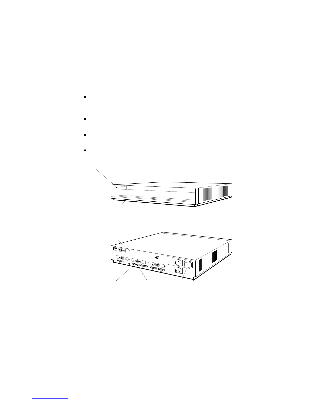
System Unit Controls and Indicators
The system unit controls and indicators, shown in Figure 1-3,
have the following uses:
The on/off switch turns the system on and off. Press down
the 0 on the switch to turn off the power. Press down the 1
on the switch to turn on the power.
The power indicator glows green when the power supply is
operating properly.
The diagnostic LEDs display binary error codes that
indicate test results.
The reset button initializes the system.
Power
supply
LED
DEC station 5000
Front view
Back view
d
i
g
i
t
a
l
0
Diagnostic
LEDs
PMAG-C
1
PMAZ-A
PMAD-A
3
Reset
button
V~100-120 A 3.0
V~220-240 A 1.7
2
V~100-120/220-240
A 7.9/4.2
Hz 50-60
W 359
2
On/off
switch
Figure 1-3. System controls and indicators
1–6 A Look at DECstation/DECsystem 5000 Model 200 Hardware
WSE2M003
Page 26

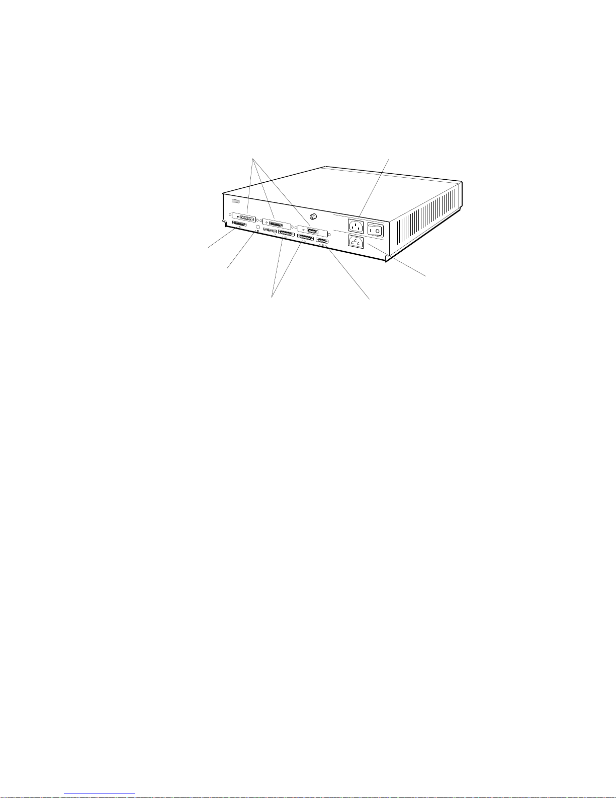
System Unit Connectors
The system unit connectors, shown in Figure 1-4, have the
following purposes:
The power connector connects the system unit power supply
and the system unit power cord.
The monitor-to-system-unit connector provides electric
power to the monitor power cord.
The ThinWire Ethernet connector links the system unit to
a ThinWire Ethernet.
The SCSI connector connects the base system SCSI
controller to a chain of external drives.
The keyboard-mouse connector links the system unit to the
keyboard-mouse cable.
The communications connectors provide printer, modem,
and console terminal connections. If there is a console
terminal, the terminal usually connects to the left
communications connector.
The option module connectors connect option modules to
external hardware. The number printed above each option
module connector is the slot number for any option module
in that slot.
A Look at DECstation/DECsystem 5000 Model 200 Hardware 1–7
Page 27
SCSI
connector
Option module
connectors
d
i
g
i
t
a
l
0
PMAG-C
Monitor-to-system-unit
connector
1
PMAZ-A
PMAD-A
3
V~100-120 A 3.0
V~220-240 A 1.7
2
V~100-120/220-240
A 7.9/4.2
Hz 50-60
W 359
2
ThinWire
Ethernet
connector
Communications
connectors
Keyboard-mouse
connector
Figure 1-4. DECstation/DECsystem 5000 connectors
Power
connector
WSE2M004
1–8 A Look at DECstation/DECsystem 5000 Model 200 Hardware
Page 28
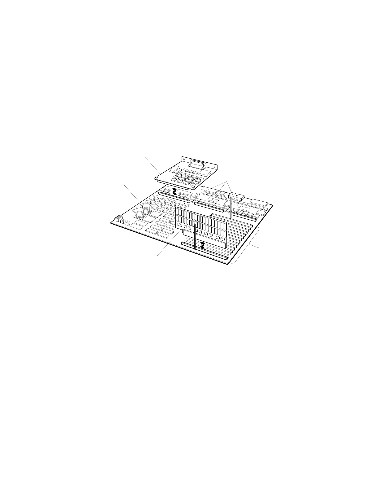
Hardware Options
The system module has slots for additional memory and
TURBOchannel option modules.
Figure 1-5 shows the location of memory and option module
expansion slots on the system module.
Option module
System
module
Memory module
Option module
expansion slots
Memory
module
expansion
slots
WSE2M005
Figure 1-5. Location of memory and expansion slots on the system
module
Additional Memory Modules
The system module has 15 expansion slots for additional
memory modules. Each memory slot can support one 8-Mbyte
memory module.
A Look at DECstation/DECsystem 5000 Model 200 Hardware 1–9
Page 29

Optional TURBOchannel Modules
The three TURBOchannel expansion slots on the system unit
support a maximum of three option modules.
Any optional SCSI or Ethernet controller modules operate in
addition to the SCSI and ThickWire Ethernet controller built in
to the system module.
Drives
Each SCSI controller supports up to seven drives that connect
in a chain that attaches to the SCSI controller through the back
of the system unit.
Monitors and Terminals
The system supports different monitors, depending on the
graphics option modules that are in the system. Refer to the
TURBOchannel Maintenance Guide for a description of the
monitors that graphics option modules support.
The system can also display text on a VT320 terminal attached
to the communications connector on the left as you face the
back of the system unit.
Keyboard and Mouse
The system uses an LK201 keyboard and VSXXX-AA mouse
that connect to the back of the system unit through the
keyboard-mouse cable.
For Further Information
For further information about the hardware described in this
chapter, refer to later chapters that discuss the hardware in
which you are interested.
For further information about TURBOchannel option modules,
drives, or monitors, refer to the TURBOchannel Maintenance
Guide.
1–10 A Look at DECstation/DECsystem 5000 Model 200 Hardware
Page 30

Service Operations
This chapter explains how to perform routine service
operations. It explains how to
Avoid electrostatic damage when handling components
Use an alternate terminal
Remove the system unit cover
Remove the front cover plate
Remove and replace the serial number plate
Install and remove terminators and loopback connectors
Enter console mode and operating mode
Use console command passwords
Boot the system software
Shut down the system software
2
Service Operations 2–1
Page 31

Using an Antistatic Kit
The Digital antistatic kit contains the equipment you need
to handle static-sensitive materials safely. When handling
static-sensitive materials, always
Place the antistatic wrist strap around your wrist and
attach the other end of the strap to the snap-on fastener
attached to the antistatic mat before you handle any
static-sensitive item.
Place the static-sensitive item on the antistatic mat when
you set it down.
Figure 2-1 shows the antistatic kit parts and their proper use.
Antistatic mat
WSE2M012
Figure 2-1. Using an antistatic kit
Wrist strap
2–2 Service Operations
Page 32

Using an Alternate Terminal
If the original monitor is not working properly, you can use an
alternate terminal to run tests.
When the alternate console is set, the alternate terminal
displays the same text as a regular system monitor. You can
use either the original or alternate keyboard to type commands.
Use a VT320 terminal set to 9600 baud.
Figure 2-2 shows how to connect an alternate terminal.
VT320 terminal
R
G
B
0
PMAG-C
1
V~100-120 A 3.0
V~220-240 A 1.7
2
PMAD-A
V~100-120/220-240
A 7.9/4.2
Hz 50-60
W 359
2
1
VT320 cable
WSE2M008
Figure 2-2. Connecting an alternate terminal
Communications
connector
3
Communications
line adapter
Service Operations 2–3
Page 33

Note: Remove any graphics modules installed in the system before
you enable the alternate terminal.
1. Install a communications line adapter on the commu-
nications line that is on the left as you face the back of
the system. Refer to ‘‘Removing and Installing Loopback
Connectors and Terminators’’ later in this chapter for
directions.
2. Insert the end of the keyboard cable into the keyboard cable
connector on the alternate terminal.
3. Insert the end of the VT320 cable into the communications
line adapter on the back of the system unit.
4. Turn on the alternate terminal.
5. Turn on the system unit. The system automatically enables
the alternate terminal after you turn on the system unit
power.
A display should appear on the alternate terminal.
To return to using the original monitor, replace the graphics
module that was installed in the system unit. After you turn on
the power, the system returns to using the original monitor.
2–4 Service Operations
Page 34

Removing and Installing the System Unit Cover
Figure 2-3 shows how to remove and install the system unit
cover.
d
i
g
i
t
a
l
0
PMAG-C
1
PMAZ-A
PMAD-A
3
Captive screw On/off switch
Figure 2-3. Remove and installing the system unit cover
V~100-120 A 3.0
V~220-240 A 1.7
2
V~100-120/220-240
A 7.9/4.2
Hz 50-60
W 359
2
WSE2M013
Service Operations 2–5
Page 35

To Remove the System Unit Cover
1. Turn off the system power.
2. Disconnect the system unit power cord.
3. Loosen the captive screw that holds the cover.
4. Face the front of the system unit and grip each side of the
system unit cover.
5. Pull the cover toward you until it comes loose from the
chassis. Then lift the cover up and away from the system
unit.
To Install the System Unit Cover
6. Place the system unit cover on the chassis. Leave at least 2
inches between the cover and the back of the system unit.
7. Slide the system unit cover toward the back of the system
unit until it pops into place.
8. Tighten the captive screw.
9. Reconnect the system unit power cord to the system unit
power connector.
2–6 Service Operations
Page 36

Removing and Installing the Front Cover Plate
Figure 2-4 shows how to remove and install the front cover
plate.
Captive
screw
Front
cover
plate
WSE2M014
Captive
screw
Figure 2-4. Removing and installing the front cover plate
System
unit
chassis
Service Operations 2–7
Page 37

To Remove the Front Cover Plate
1. Make sure the system power is off.
2. Remove the system unit cover. Refer to the previous section
for directions.
3. Loosen the two captive screws.
4. Tilt the top of the plate down and lift it away from the
chassis.
To Install the Front Cover Plate
5. Make sure the system power is off.
6. Insert the tabs on the bottom of the plate into the slots in
the front of the chassis.
7. Tilt the plate forward.
8. Tighten the two captive screws.
2–8 Service Operations
Page 38

Removing and Installing a Serial Number Plate
To Remove a Serial Number Plate
1. Turn off the system unit power.
2. Remove the system unit cover. Refer to ‘‘Removing and
Installing the System Unit Cover’’ earlier in this chapter
for directions.
3. Peel the tamper-proof tape off the two nuts that hold the
serial number plate.
4. Use a crescent wrench to remove the two nuts that hold the
serial number plate.
5. Pull the serial number plate away from the system unit.
To Install a Serial Number Plate
1. Make sure the system unit power is off and the system unit
cover is removed.
2. Pass the two posts on the back of the serial number plate
through the holes in the back of the system unit.
3. Tighten the two nuts onto the posts.
4. Apply one piece of security tape over each nut and the post
surrounding it.
Service Operations 2–9
Page 39

W 359
Hz 50-60
A 7.9/4.2
V~100-120/220-240
WSE2M050
Page 40

Removing and Installing Loopback Connectors and
Terminators
To remove and install a ThinWire terminator, follow the
directions in Figure 2-6.
To remove and install a ThickWire loopback connector,
follow the directions in Figure 2-7.
To remove and install a communications loopback connector,
follow the directions in Figure 2-8.
To remove and install a SCSI chain terminator, follow the
directions in Figure 2-9.
To remove and install a communications line adapter, follow
the directions in Figure 2-10.
Service Operations 2–11
Page 41

To Remove a ThinWire Terminator
1. Twist the collar on the ThinWire T-connector as far as
possible to the left.
2. Pull the T-connector off of the system unit connector.
To Install a ThinWire Terminator
1. Press a terminator onto each unused end of the T-connector.
Turn the terminator to the right until it locks into place.
2. Push the T-connector collar onto the ThinWire connector on
the system unit.
3. Turn the T-connector collar to the right until it slips past
the connector tabs and slides into place.
ThinWire T-connector
ThinWire terminators
d
i
g
i
t
a
l
PMAG-C
ThinWire Ethernet connector
0
1
PMAZ-A
PMAD-A
3
V~100-120 A 3.0
V~220-240 A 1.7
2
V~100-120/220-240
A 7.9/4.2
Hz 50-60
W 359
2
WSE2M009
Figure 2-6. Removing and installing a ThinWire Ethernet terminator
2–12 Service Operations
Page 42

To Remove a ThickWire Loopback Connector
1. Firmly grip the ThickWire loopback connector.
2. Pull the ThickWire loopback connector away from the
ThickWire connector on the system unit.
To Install a ThickWire Loopback Connector
1. Align the wide end of the loopback connector and the wide
end of the ThickWire Ethernet connector.
2. Firmly press the loopback connector onto the ThickWire
Ethernet connector.
System unit
ThickWire connector
ThickWire
loopback
connector
Figure 2-7. Removing and installing a ThickWire loopback connector
0
PMAG-C
1
PMAZ-A
PMAD-A
3
V~100-120 A 3.0
V~220-240 A 1.7
2
V~100-120/220-240
A 7.9/4.2
Hz 50-60
W 359
2
WSE2I026
Service Operations 2–13
Page 43

To Remove a Communications Loopback Connector
1. Firmly grip the communications loopback connector.
2. Pull the communications loopback connector away from the
communications connector.
To Install a Communications Loopback Connector
1. Align the wide end of the loopback connector and the wide
end of the communications connector.
2. Firmly press the loopback connector onto the communica-
tions connector.
0
PMAG-C
1
PMAD-A
V~100-120 A 3.0
V~220-240 A 1.7
2
V~100-120/220-240
A 7.9/4.2
Hz 50-60
W 359
2
Communications
loopback
connector
Figure 2-8. Removing and installing a communications loopback
2–14 Service Operations
connector
1
Communications
connector
3
WSE2M048
Page 44

To Remove a SCSI Chain Terminator
1. Push the wire brackets away from the terminator.
2. Pull the terminator off of the SCSI connector.
To Install a SCSI Chain Terminator
1. Firmly press the chain terminator onto the unused
connector on the drive at the end of the chain.
2. Fasten the SCSI connector wire brackets onto the SCSI
terminator.
Wire brackets
SCSI chain terminator
WSE2M040
Figure 2-9. Removing and installing a SCSI chain terminator
Service Operations 2–15
Page 45

To Remove a Communications Line Adapter
1. Loosen the two screws that hold the adapter to the
communications connector.
2. Pull the communications line adapter away from the system
unit.
To Install a Communications Line Adapter
1. Firmly press the communications line adapter onto the
communications connector.
2. Tighten the two screws.
0
PMAG-C
1
PMAD-A
V~100-120 A 3.0
V~220-240 A 1.7
2
V~100-120/220-240
A 7.9/4.2
Hz 50-60
W 359
2
Figure 2-10. Removing and installing a communications line adapter
2–16 Service Operations
1
3
Communications
connector
Communications
line adapter
WSE2M037
Page 46

Entering Console and Operating Modes
The system operates in either of two modes:
Console mode
Use console mode to
Run tests
Display hardware configurations
Set environment variables
Boot the system software
In console mode, the system displays the prompt
R>. The system displays the prompt >> whenever you
>> or
can use all console commands. If the system displays the
prompt R>, you can use only the boot and password console
commands until you enter the password.
Operating mode
In operating mode, the system displays the appropriate
ULTRIX prompt. Use operating mode for regular system
operation.
Service Operations 2–17
Page 47

To Enter Console Mode
Enter console mode by turning on the system power or pressing
the reset button. If the system is running software, shut down
the system software before you enter console mode. When you
turn on the system power, the system completes a power-up
self-test before displaying the console prompt.
If the system displays the prompt
R>, you can use only the boot
and password commands until you enter a password. To enter
the password, type passwd and press Return. At the prompt
pwd:, type the password and press Return. When you have
access to all console commands, the system displays the prompt
>>.
For information about setting and removing console command
passwords, refer to ‘‘Using Console Command Passwords’’ later
in this chapter.
To Enter Operating Mode
Enter operating mode by booting the system. Refer to ‘‘Booting
the System Software’’ later in this chapter for directions.
2–18 Service Operations
Page 48

Using Console Command Passwords
You can set the system so that you can use only the boot and
password commands until you enter a password. A system that
requires a password before you can use all console commands
displays the prompt R> until you enter the correct password.
To be able to use all console commands on a system that
requires a password, type passwd at the prompt R>. Then type
the password and press Return. The system then allows you to
use all console commands. Whenever all console commands are
available, the system uses the prompt >>.
To Set or Change a Password
To set or change a password, use the password command with
the -s option.
1. Type passwd -s at the prompt >> and press Return.
2. At the prompt pwd:, type the new password and press
Return.
3. The system repeats the prompt pwd:. Enter the password a
second time at the prompt
pwd:.
Note that passwords must
Have at least six characters
Have no more than 32 characters
Use uppercase and lowercase letters the same as when you
first entered the password
If the two password entries match, the entry becomes the new
password. If the two entries do not match, the old password
remains in effect.
To Remove a Requirement for a Password
To remove a requirement for a password, type passwd -c at the
prompt
>> and press Return.
Service Operations 2–19
Page 49

To Erase a Password You Do Not Know
You can erase a password by inserting a clear-nonvolatile-RAM
(NVR) jumper. After you insert a clear-NVR jumper, you will
need to reset all environment variables.
To erase a password you do not know,
1. Turn off the system power.
2. Install the clear-NVR jumper. Refer to the following section
for installation directions.
3. Turn on the system and wait for the console prompt to
appear.
4. Turn off the system again.
5. Remove the clear-NVR jumper.
6. Turn on the system power.
7. Use the setenv command to reset environment variables to
the values you want.
After you erase the password, the console commands have no
password protection until you set a new password.
2–20 Service Operations
Page 50

Inserting and removing a clear-NVR jumper
Figure 2-11 shows how to insert and remove the clear-NVR
jumper.
Clear NVR
Clear NVR pins
System module
Figure 2-11. Inserting and removing a clear-NVR jumper
WSE2M047
Service Operations 2–21
Page 51

To insert the jumper,
1. Turn off the system unit.
2. Remove the system unit cover. Refer to ‘‘Removing and
Installing the System Unit Cover’’ earlier in this chapter
for directions.
3. Locate the clear-NVR pins on the system module. The
clear-NVR jumper pins are a two-pin fixture.
4. Slide the jumper entirely over the clear-NVR pins.
To remove the jumper,
1. Make sure the system power is off.
2. Remove the system unit cover if it is on the system unit.
3. Slide the jumper up and away from the clear-NVR pins.
2–22 Service Operations
Page 52

Booting the System Software
To boot the system, use the boot command.
Booting a system can take several minutes. If the system
displays the ULTRIX prompt
appears, press Ctrl-D to continue with the boot operation.
If the boot is successful, the monitor displays the prompt
login:.
If the system fails to boot, do the following:
1. Use the printenv command to display the environment
variables table.
2. Use the setenv command to set the boot environment
variable to a hard disk or to the network that contains the
system software.
3. Use the boot command to boot the system.
For a detailed explanation of these console commands, refer to
Appendix C.
If the system still does not boot, check any boot error messages
that appear on the monitor. Refer to Appendix C to find the
meaning of boot error messages.
# before the prompt login:
Service Operations 2–23
Page 53

Shutting Down the System Software
If the system is running ULTRIX software, shut down the
system before you perform customer service. To shut down the
software, type the following command at the ULTRIX prompt:
/etc/shutdown -h (now| hhmm| +n)
Specify the now parameter to shut down the software
immediately.
Specify hhmm to shut down the software at a specified
time. Replace hhmm with the hour and minute the
shutdown begins, where
hh represents the hour to begin the shutdown.
mm represents the minute to begin the shutdown.
Specify +n to shut down the software in a specified number
of minutes. Replace n with the number of minutes until
shutdown begins.
The monitor displays the prompt >> or R> when shutdown is
complete.
2–24 Service Operations
Page 54

Troubleshooting Tools
This chapter explains the system troubleshooting tools. It
explains how to
Use different types of tests
Set up tests for groups of selected modules
Interpret test results
Examine and interpret error logs
Use boot error messages
Use console status messages
3
Troubleshooting Tools 3–1
Page 55

Using Tests
The system uses two types of tests to check system hardware
operation:
Subtests can be individual tests or test scripts, which are
groups of individual tests. If you run a test script, you can
select one of several prepared scripts or create your own.
Using Slot Numbers in Test Commands and Error Messages
Test commands and error messages include slot numbers that
identify the hardware to which the test command or error
message refers.
The slot number for the system module and memory modules
is always 7. Figure 3-1 shows the slot numbers for the SCSI
and ThinWire controllers on the system module and the option
modules.
Power-up self-tests, which run a comprehensive test of the
system hardware
Subtests, which test individual modules that you choose
Slot number 0 refers
to the module in
option slot 0. option slot 1.
Slot number 5 refers
to the SCSI controller
on the system module.
Figure 3-1. Slot numbers for system hardware
3–2 Troubleshooting Tools
Slot number 1 refers Slot number 2 refers
to the module in
to the module in
option slot 2.
0
1
PMAD-A
3
V~100-120 A 3.0
V~220-240 A 1.7
2
V~100-120/220-240
A 7.9/4.2
Hz 50-60
W 359
2
Slot number 6 refers
to the ThinWire Ethernet
controller on the system module.
WSE2M060
Page 56

Running Power-Up Self-Tests
The system runs a power-up self-test when you turn on the
system power. The monitor and diagnostic LEDs report any
errors the power-up self-test detects. To find the corrective
action for any error codes the power-up self-test reports, refer
to Chapter 4.
Note: If the monitor displays the message PDE3: x, where x
represents an option module slot number, the system contains
incompatible ROM chips. Upgrade the system ROM chips if the
PDE3: x message appears.
You can specify a quick or thorough power-up self-test script to
run when the system powers up.
The quick test script is a limited script that minimizes the
time until the system boots.
The thorough script runs an extensive check of system
hardware. The thorough power-up self-test script is most
useful for field service troubleshooting.
To select a power-up self-test script, use the setenv command
to set the testaction environment variable. Type setenv
testaction (q|t) and press Return.
Specify q to select the quick test.
Specify t to select the thorough test.
Troubleshooting Tools 3–3
Page 57

Running Subtests
In addition to the power-up self-test, you can use subtests to
troubleshoot. Subtests run individual tests or test scripts.
Running Individual Tests
To run an individual test, type
t [-l] slot/test [arg1][arg2][arg3]...
When you type an individual test command,
t is the command to run a test.
Include the optional -l parameter to make the test repeat
continuously until you type Ctrl-C or reset the system.
Replace slot with the slot number of the module to be
tested. Table 3-1 lists the slot numbers assigned to each
module.
Replace test with the name of the particular test you want
to run.
The optional extended arguments (arg-1 and so on) specify
individual test conditions. Refer to Appendix D for an
explanation of the arguments used for each test.
Table 3-1. Slot Numbers Used in Test Commands
Slot Number Unit Tested
0 Option module in slot 0 (slot farthest from the power switch)
1 Option module in slot 1 (middle option slot)
2 Option module in slot 2 (slot nearest the power switch)
3 Reserved
4 Reserved
5 SCSI controller on the system module
6 Ethernet controller on the system module
7 System module or memory module
3–4 Troubleshooting Tools
Page 58

Running Test Scripts
Use the sh command to run a test script.
To run a test script once and then stop, type sh script,
where you replace script with the name of the test script
you want to run. Then press Return.
To have a test script run and keep repeating until you press
Ctrl-C, include the optional -l parameter in the command.
Type sh -l script, where you replace script with the name of
the test script you want to run. Then press Return.
Displaying Lists of Available Tests
To display all individual tests available for a specific module,
type t slot/?, where you replace slot with the slot number of the
module for which you want a test listing. Then press Return.
A list of tests similar to this sample listing of tests for the
system module appears on the monitor:
cache/data I or D[D] address[80050000]
cache/isol I or D[D]
cache/reload I or D[D] address[80050000]
cache/seg I or D[D] address[80050000]
ecc/gen address[A0100000]
fpu
mem board[0] thrsld[10] pattern[55555555]
mem/init
mem/float10 address[A0100000]
mem/select
mfg/done
misc/pstemp
misc/refresh
misc/wbpart
rtc/nv pattern[55]
rtc/period
rtc/regs
rtc/time
tlb/probe
tlb/reg pattern[55555555]
In this list,
The leftmost column lists the commands for tests that are
available for the specific module.
Troubleshooting Tools 3–5
Page 59

Entries in the other columns represent the individual test
parameters, if any. The value in brackets next to each
parameter is the default value for that parameter.
For a detailed explanation of individual self-tests and their
parameters, refer to Appendix D.
To display existing scripts that test an individual module
To display all the scripts that do not loop, type ls slot, where
slot represents the slot number of the module for which you
want all test scripts listed. Then press Return.
A display of scripts and other objects that are in the module
then appears on the screen. This sample listing is a portion
of the ls display for slot 7. This portion lists some of the test
scripts present in the system module and memory module.
7/pst-m
7/pst-q
7/pst-t
7/test-cpu
7/test-dz-m
7/test-dz-q
7/test-dz-t
7/test-misc
7/test-rtc
7/test-mem-m
7/test-mem-q
7/test/mem-t
3–6 Troubleshooting Tools
Page 60

Creating Test Scripts
You can create test scripts that test modules under test
conditions you choose.
To create a test script,
1. Type script name, where you replace name with the name
that you want to give the script you are creating. Then
press Return.
2. Type the test commands for the tests that you want to
include in the script. When you type test commands,
Type test commands in the same order that you want
the tests to run in the test script.
Specify any options that you want to include in each
test when you type the test command.
Press Return after you finish typing each individual
test command.
3. Finish creating the test script by pressing Return twice
after you enter the name of the last test in the test script.
4. To run the script you just created, type sh name, where
you replace name with the name you assigned the script,
and press Return.
Note: The system stores this test script in volatile memory. The test
script is lost when you turn off the system unit or press the reset
button. You can store only one script at a time.
Troubleshooting Tools 3–7
Page 61

Interpreting Test Error Messages
For every error that a self-test detects, an error message
appears on the screen. Error messages appear in the following
format:
?TFL slot/test (code: description)[module].
?TFL indicates that an error occurred.
slot represents the slot number of the module that reported
the error.
test represents the individual test that failed.
code represents a code that indicates which part of the test
failed.
description represents a possible message that describes the
failure.
module represents the module identification number.
For an explanation of individual system module and memory
module error messages, refer to Appendix D.
For an explanation of individual SCSI, Ethernet, and
TURBOchannel option error messages, refer to the
TURBOchannel Maintenance Guide.
This is a sample error message:
?TFL 7/dz/alrm (bad interrupt) [KN02-AA]
This error message states that the module in slot number 7, the
system module, failed the serial line silo alarm test.
The additional message
failed the interrupt operation.
3–8 Troubleshooting Tools
(bad interrupt) indicates that the test
Page 62

Using Error Logs
The system records events and errors in the ULTRIX error logs.
Use the memory error, error and status register, and system
overheat error logs to troubleshoot intermittent problems.
Note: The ULTRIX error logs are not the same as the test error logs
that appear when you use the erl console command. The test error log
is a record of errors reported by tests run in console mode.
The following paragraphs describe ULTRIX error log formats
and error log parts useful in troubleshooting.
Examining Error Logs
You must be in ULTRIX to examine error logs. At the ULTRIX
prompt, type /etc/uerf -R| more and press Return. A full
display of error log entries appears on the monitor.
The first part of each error log describes the type of error and
system conditions in effect when the error occurred. The last
part of each log provides specific information about the error
and its location.
The first part of all error logs is similar to this:
----- EVENT INFORMATION ----EVENT CLASS OPERATIONAL EVENT
OS EVENT TYPE 300. SYSTEM STARTUP
SEQUENCE NUMBER 0.
OPERATING SYSTEM ULTRIX 32
OCCURRED/LOGGED ON Tue Oct 24 09:06:16 1989
OCCURRED ON SYSTEM GRANITE
SYSTEM ID x82020120 HW REV: x20
FW REV: x1
CPU TYPE: R2000A/R3000
PROCESSOR TYPE KN02/R3000
Troubleshooting Tools 3–9
Page 63

In this display,
EVENT CLASS lists the error log’s general category.
Possible EVENT CLASS categories are
Operational events, which are changes in system
operation that are not errors
Error events, which are actual errors in system
operation
OS EVENT TYPE describes the type of error or event
recorded in the log. Table 4-3 lists possible operating
system event types and their codes. For information about
memory, error and status register, and overheat error logs,
refer to the following section ‘‘Distinguishing Event Types’’
and to the discussion of the particular log in which you are
interested.
SEQUENCE NUMBER lists the order in which the system
logged the event.
OPERATING SYSTEM lists the system’s version of
ULTRIX.
OCCURRED/LOGGED ON shows the time the error
occurred.
OCCURRED ON SYSTEM lists the individual system that
reported the error.
SYSTEM ID includes several listings:
The first number to the right of SYSTEM ID is the
system ID.
HW REV lists the system hardware revision number.
FW REV lists the system firmware revision number.
CPU TYPE shows the type of CPU used in the system.
PROCESSOR TYPE lists the type of processor chip used in
the system.
The remaining error log entry is different for each error log
event type. For an explanation of entries contained in memory,
error and status register, and overheat error logs, refer to the
next section.
3–10 Troubleshooting Tools
Page 64

Distinguishing Event Types
The second line of each error log lists the code number and
name of the error log event type.
The following sections describe memory, error and status, and
system overheat error logs. For a detailed explanation of other
error logs that involve the system unit, refer to the ULTRIX
documentation.
Memory error logs
Memory error logs record errors that occur in the memory
modules. This is a sample of the error log sections that are
unique to memory error logs.
----- UNIT INFORMATION ----UNIT CLASS MEMORY
UNIT TYPE KN02 MEMORY
ERROR SYNDROME MEMORY CRD ERROR
----- ERROR & STATUS REGS ----EPC x8006DF4C
KN02 STAT REG x07C20001 IO INT 0 PENDING
19,200 BAUD
8 MB MEM MODULE
ECC CMD x0
IO INT 1 ENABLED
IO INT 6 ENABLED
IO INT 7 ENABLED
NORMAL MODE
REFRESH EVEN MEM MODULES
ERROR ADDR REG xD01B37BA
PHYSICAL ERROR ADDR x006CDEE8
CHECK SYNDROME x00108884 SYND BITS x4
----- ADDITIONAL INFO ----CONTROLLER NO. 1.
ERRS ON THIS ADDR 1.
UNSECURE
CPU MEM READ ECC
SINGLE BIT ERROR
CHECK BITS x8
MODULE NUM. x0
ERROR COUNT 1.
INVALID PC MEMINTR
Troubleshooting Tools 3–11
Page 65

The UNIT INFORMATION section describes the type of module
that reported the error.
UNIT CLASS shows that the error occurred in a memory
module.
UNIT TYPE lists the particular type of memory module in
which the error occurred.
ERROR SYNDROME describes the nature of the error.
The ERROR & STATUS REGS section lists the error and status
register contents followed by phrases that describe the register
contents.
EPC indicates that this is an exception program counter.
KN02 STAT REG lists the contents of the CPU status
register (CSR).
ERROR ADDR REG describe the specific error type.
PHYSICAL ERROR ADDR is the address in the hardware
where the error occurred.
CHECK SYNDROME entries describe the actual error and
the module where it occurred.
SYND BITS lists the bits in the check syndrome
register.
The second line states whether this is a single bit or a
mulitbit error.
The third line shows the check bits.
MODULE NUM shows the slot number of the module
that reported the error.
ERROR COUNT shows the total number of errors that
have occurred in this module since the last time the
software was booted.
The last line shows whether this is a bus error or
memory interrupt error.
The ADDITIONAL INFO section lists the controller number
and total number of errors that have occurred at this
address.
3–12 Troubleshooting Tools
Page 66

Error and status register error logs
Error and status register error logs record nonmemory errors.
This is a sample of the error log sections that are unique to
error and status register error logs.
----- ERROR & STATUS REGS ----CAUSE x80002000
INTERRUPT
STATUS x0000FE04 CURRENT INTERRUPT STATE DISABLED
SP xFFFFDC58
KN02 STAT REG x05C20001 IO INT 0 PENDING
ERROR ADDR REG xE7B00000
PHYSICAL ERROR ADDR x1EC00000
EXCEPTION CODE EXTERNAL
HW INTERRUPT 3 PENDING
BRANCH DELAY SET
CURRENT MODE KERNEL
PREVIOUS INTERRUPT STATE ENABLED
PREVIOUS MODE KERNEL
OLD INTERRUPT STATE DISABLED
OLD MODE KERNEL
SW INTERRUPT 1 ENABLED
HW INTERRUPT 0 ENABLED
HW INTERRUPT 1 ENABLED
HW INTERRUPT 2 ENABLED
HW INTERRUPT 3 ENABLED
HW INTERRUPT 4 ENABLED
HW INTERRUPT 5 ENABLED
CACHE STATE NORMAL
19,200 BAUD
8 MB MEM MODULE
ECC CMD x0
IO INT 1 ENABLED
IO INT 6 ENABLED
IO INT 7 ENABLED
NORMAL MODE
REFRESH ODD MEM MODULES
UNSECURE
CPU I/O WRITE TIMEOUT
Troubleshooting Tools 3–13
Page 67

The ERROR & STATUS REGS section lists the error and status
register contents followed by phrases explaining these values.
CAUSE lists the type of event that caused the error.
STATUS lists various system settings in effect when the
error occurred.
SP is a stack pointer that identifies where the CPU
contents were sent when the error occurred.
KN02 STAT REG lists the contents of the CPU status
register.
ERROR ADDR REG describes the specific error type.
PHYSICAL ERROR ADDR indicates where in the
hardware the error occurred. Refer to ‘‘Using Error Logs
to Troubleshoot’’ in Chapter 4 for possible physical error
address values and the hardware they indicate.
System overheat error messages
If the system overheats, ULTRIX records the error and the
following message on the monitor:
"System overheating - suggest shutdown and power-off"
For Further Error Log Information
To determine how to respond to a specific error message, refer
to ‘‘Interpreting Test Results’’ in Chapter 4.
To interpret memory, error and status register, and overheat
logs, refer to ‘‘Using Error Logs to Troubleshoot’’ in Chapter 4.
For an explanation of other error logs, refer to the ULTRIX
documentation for the uerf function.
For an explanation of error logs for SCSI devices, refer to the
documentation for the SCSI device that the error log discusses.
3–14 Troubleshooting Tools
Page 68

Identifying Failed FRUs
This chapter explains how to
Follow the troubleshooting process for this system
Interpret power-up self-test error messages to identify
FRUs
Troubleshoot when the power-up self-test does not complete
Interpret error logs to find intermittent failures
Troubleshoot when the printer, modem, or alternate
terminal does not operate properly
4
Identifying Failed FRUs 4–1
Page 69

Troubleshooting Process
Troubleshoot the system as follows:
1. Make sure there is power to the system unit. If the system
unit has no power, refer to ‘‘Power Supply’’ in Chapter 5 to
troubleshoot.
2. Turn on the system and check the results of the power-up
self-test.
If the power-up self-test displays an error message on
the monitor, refer to Table 4-1 to troubleshoot.
If the power-up self-test does not complete, refer to
Table 4-2 to troubleshoot.
If the monitor has no display, refer to the TURBOchannel
Maintenance Guide to troubleshoot.
3. Run the system test. Type test and press Return. The
system test runs a comprehensive check of the system
hardware. If this test returns an error code, refer to
Table 4-1 to troubleshoot.
4. If none of these tests reports a problem, check the memory
modules. Refer to ‘‘Memory Modules’’ in Chapter 5 to
troubleshoot.
5. If the system still reports no errors, but the problem
persists, examine the error logs. Refer to ‘‘Using Error Logs
to Troubleshoot’’ later in this chapter to troubleshoot.
6. If the system reports no errors, but the printer, modem, or
alternate terminal does not operate properly, perform an
external loopback serial line test. Refer to ‘‘Troubleshooting
When a Printer, Modem, or Alternate Terminal Does Not
Operate Properly’’ later in this chapter to troubleshoot.
7. If the system fails to boot, use any console error messages
that appear on the monitor to troubleshoot. Refer to
Appendix E to interpret console error messages.
4–2 Identifying Failed FRUs
Page 70

Interpreting Test Results
Use the error messages that appear on the monitor and on the
diagnostic LEDs to identify failed FRUs.
Interpreting Error Messages That Appear on the Monitor
Error messages on the monitor have the form
?TFL slot/test_name (n: description)[module]
slot represents the slot number of the FRU that reported
the failure.
test_name is the name of the individual test that failed.
The string (n: description [module] includes additional
information that describes the error.
Table 4-1 shows the corrective action indicated by each test that
displays an error message on the monitor.
Interpreting LED Displays
In diagnostic LED displays, the number on the four leftmost
LEDs, as you face the back of the system, is the slot number of
the FRU that failed.
Table 4-2 shows the corrective action indicated by each code on
the diagnostic LED displays.
To determine the exact cause of an FRU failure, refer to the
troubleshooting information in the chapter that discusses that
FRU.
Identifying Failed FRUs 4–3
Page 71

Table 4-1. Interpreting Test Error Messages Displayed on the Monitor
Test Listed in the
Error Message Component Tested Corrective Action
box Graphics module for which
the slot number appears
Refer to the TURBOchannel Maintenance
Guide to troubleshoot.
in the error message
cntl SCSI controller for which
Refer to Chapter 5 for directions.
the slot number appears
in the error message.
curs Graphics module for which
the slot number appears
Refer to the TURBOchannel Maintenance
Guide to troubleshoot.
in the error message
dmaaddrs Graphics module for which
the slot number appears
in the error message
Refer to ‘‘Two_Dimensional Graphics
Accelerator Modules’’ in the TURBOchannel
Maintenance Guide to troubleshoot.
dz/cache System module Replace the system module and chassis.
ecc Memory modules Refer to ‘‘Memory Modules’’ in Chapter 5
to troubleshoot.
esar
ext
fb
fbfill
Ethernet controller Ethernet controller for which the slot
number appears in the error message.
Graphics module for which
the slot number appears
in the error message
Refer to ‘‘Two-Dimensional Graphics
Accelerator Modules’’ in the TURBOchannel
Maintenance Guide to troubleshoot.
fpu System module Replace the system module and chassis.
Refer to Chapter 5 for directions.
int Ethernet controller or
graphics module
Ethernet controller or graphics module
for which the slot number appears in
the error message. Refer to ‘‘Ethernet
Controller Modules’’ or to ‘‘Color Frame-
Buffer Graphics Modules’’ in the
TURBOchannel Maintenance Guide
to troubleshoot.
intr-dma Graphics module for which
the slot number appears
in the error message
Refer to ‘‘Two-Dimensional Graphics
Accelerator Modules’’ in the TURBOchannel
Maintenance Guide to troubleshoot.
mem Memory modules Refer to ‘‘Memory Modules’’ in Chapter 5
to troubleshoot.
(continued on next page)
4–4 Identifying Failed FRUs
Page 72

Table 4-1 (Cont.). Interpreting Test Error Messages Displayed on the Monitor
Test Listed in the
Error Message Component Tested Corrective Action
misc/kbd
misc/mouse
Keyboard or mouse Refer to ‘‘Keyboard and Mouse’’ in
Chapter 5 to troubleshoot.
misc/pstemp Power supply Refer to ‘‘Power Supply’’ in Chapter 5 to
troubleshoot.
misc/wbpart System module Replace the system module and chassis.
Refer to Chapter 5 for directions.
ptrns
patrns
Graphics module for which
the slot number appears
in the error message
Refer to ‘‘Color Frame-Buffer Graphics
Modules’’ or ‘‘Two-Dimensional
Graphics Accelerator Modules’’ in the
TURBOchannel Maintenance Guide to
troubleshoot.
ram
reg
Ethernet controller for
which the slot number
appears in the error
Refer to ‘‘Ethernet Controller Modules’’
in the TURBOchannel Maintenance
Guide to troubleshoot.
message
shades
stamp
stic
Graphics module for which
the slot number appears
in the error message
Refer to ‘‘Color Frame-Buffer Graphics
Modules’’ or ‘‘Two-Dimensional
Graphics Accelerator Modules’’ in the
TURBOchannel Maintenance Guide to
troubleshoot.
target SCSI bus for which the
slot number appears in
the error message.
Refer to ‘‘SCSI Controller Modules’’ in
the TURBOchannel Maintenance Guide
to troubleshoot.
tlb System module Replace the system module and chassis.
Refer to Chapter 5 for directions.
vdac
vdacsig
vram
Graphics module for which
the slot number appears
in the error message
Refer to ‘‘Color Frame-Buffer Graphics
Modules’’ or ‘‘Two-Dimensional
Graphics Accelerator Modules’’ in the
TURBOchannel Maintenance Guide to
troubleshoot.
Identifying Failed FRUs 4–5
Page 73

Troubleshooting When the Power-Up Self-Test Does Not
Complete
If the power-up self-test does not complete, the left set of
diagnostic LEDs display an error code that indicates the slot
number of the FRU that caused the power-up self-test to stop.
Table 4-2 lists the corrective action for each location where the
test can stop.
Table 4-2. Troubleshooting When the Power-Up Self-Test Does Not Complete
Left LED Display
(1=0n) Corrective Action
None; test does
not start.
1111 A hardware problem is preventing the diagnostics from executing.
0111 Replace the memory module in memory slot 0 and repeat the
0110 Replace the system module and chassis.
0101 Replace the system module and chassis.
0010
0001
0000 If the right LED display is 0000, the self-test completed
Check for loose and damaged connectors and reseat any loose
modules. If the system still does not start, there is a basic problem
in the system. Contact the Digital Customer Support Center.
Contact the Digital Customer Support Center for assistance.
power-up self-test. If the power-up self-test still stops and the
left diagnostic LEDs display 0111, replace the system module and
chassis.
Replace the option module that has the same slot number as the
left LED display.
If the problem option module is a 2D graphics accelerator module,
replace the VSIMM and repeat the power-up self-test before you
replace the 2D graphics accelerator module. If the 2D graphics
accelerator module still fails after you replace the VSIMM, replace
the 2D graphics accelerator module.
successfully.
If the the left LED display is not 0000, replace the option module
in option slot 0.
4–6 Identifying Failed FRUs
Page 74

Using Error Logs to Troubleshoot
The event type listed on the second line of the error log
describes the general event that the error log recorded.
Table 4-3 lists possible event type codes and their meaning.
Table 4-3. Error Log Event Types
Code Event Type
100 Machine check
101 Memory error
102 Disk error
103 Tape error
104 Device controller error
105 Adapter error
106 Bus error
107 Stray interrupts
108 Asynchronous write error
109 Exception or fault
113 CPU error and status
200 Panic (bug check)
250 Informational ASCII message
251 Operational message
300 System startup message
310 Time change message
350 Diagnostic information
The following information explains how to interpret memory,
error and status register, and overheat error logs. To interpret
other error logs, refer to the ULTRIX documentation or the
documentation for the device that the error log discusses.
Identifying Failed FRUs 4–7
Page 75

Memory Error Logs
Use these parts of the memory error log to determine the error:
The number after MODULE NUM in the log’s check
syndrome section is the slot number of the memory module
that reported the error.
The phrase after ERROR ADDR REG describes the type of
error that occurred.
Replace the memory module in the slot for which the number
appears in the MODULE NUM listing. Refer to ‘‘Memory
Modules’’ in Chapter 5 for directions.
Error and Status Register Error Logs
Use the last two lines in the error and status register error logs
to determine the error and its location.
The phrase after ERROR ADDR REG describes the error
that occurred.
The number after PHYSICAL ADDR is the physical address
where the error occurred. Table 4-4 lists the system
hardware physical addresses and the FRUs in which they
are located.
Although addresses 1EC00000 to 1F3FFFFF are reserved, error
logs sometimes list these as the error’s physical address. Errors
attributed to these addresses are system module errors.
4–8 Identifying Failed FRUs
Page 76

Table 4-4. Hardware Physical Addresses
Physical Address Range Indicated Hardware
00000000 to 1DFFFFFF Main memory
1E000000 to 1E3FFFFF Module in option slot 0
1E400000 to 1E7FFFFF Module in option slot 1
1E800000 to 1EBFFFFF Module in option slot 2
1EC00000 to 1EFFFFFF Reserved
1F000000 to 1F3FFFFF Reserved
1F400000 to 1F7FFFFF SCSI controller on the system module
1F800000 to 1FBF0000 Ethernet controller on the system module
1FC00000 to 1FFFFFFF System module interface
Replace the FRU that contains the hardware indicated by the
error log. For directions, refer to the section in Chapter 5 of
this guide, or the TURBOchannel Maintenance Guide that
discusses the FRU you want to replace.
Overheat Error Messages
If the system reports an overheat error, shut down the system
software and then turn off the system power. Refer to ‘‘Power
Supply’’ in Chapter 5 to troubleshoot the power supply fans.
Identifying Failed FRUs 4–9
Page 77

Troubleshooting When a Printer, Modem, or Alternate
Terminal Does Not Operate Properly
If the system tests report no errors, but a printer, modem, or
alternate terminal does not operate properly, run an external
loopback serial line test to isolate the problem.
Before you run the external loopback serial line test, make sure
the following items are installed on the back of the system unit:
Communications loopback connectors on both communications connectors
A keyboard-mouse cable that has the following attached:
A keyboard attached to the keyboard connector
A mouse or mouse loopback connector attached to the
mouse connector
To run the external loopback serial line test, type
t dz/modem/ [line][cts-lbk]. Then press Return.
When you type the external loopback test command,
Use the line parameter to specify the serial line you want
to test.
Specify comm to test the communications line that is
on the right as you face the back of the system.
Specify port to test the communications line that is on
the left as you face the back of the system.
Use the cts-lbk parameter to specify the type of test to
run.
Specify n to run a data-leads-only test.
Specify y to run a clear-to-send test.
If the external loopback serial line test reports an error, the
serial line controller is faulty. Replace the system module and
chassis. Refer to ‘‘System Module’’ in Chapter 5 for directions.
If the external loopback serial line test succeeds, the printer or
modem is faulty. Refer to the printer or modem service guide to
troubleshoot.
4–10 Identifying Failed FRUs
Page 78

For Further Information
For an explanation of troubleshooting the SCSI, Ethernet,
TURBOchannel options, and the drives and monitors they
support, refer to the TURBOchannel Maintenance Guide.
Identifying Failed FRUs 4–11
Page 79

5
Basic Hardware
This chapter discusses hardware, troubleshooting procedures,
and removal and installation instructions for the following
FRUs:
System module and chassis
Memory module
Keyboard
Mouse
Power supply
Basic Hardware 5–1
Page 80

System Module and Chassis
System Module and Chassis Hardware
The system module and chassis, shown in Figure 5-1, provides
basic system functions. The system module and chassis are a
single unit that contains
Two diagnostic system ROMs
One Ethernet station address register (ESAR) chip
One SCSI controller with its own diagnostic ROM
One ThinWire Ethernet controller with its own diagnostic
ROM
Two communications line controllers
Three option module slots
Fifteen memory module slots
One metal system chassis
Diagnostic
ROMs
Communications line controllers
ThinWire Ethernet controller
System module
power connectors
Figure 5-1. System module and chassis
5–2 Basic Hardware
SCSI controller
WSE2M016
Page 81

Troubleshooting the System Module
Table 5-1 lists the appropriate response to each system module
test error message.
Table 5-1. Interpreting System Module Error Messages
Failed
System
Module Test Component Tested Corrective Action
cache/
dz
ecc Memory module Refer to ‘‘Memory Modules’’ later in this
fpu System module Replace the system module and chassis.
mem Memory module Refer to ‘‘Memory Modules’’ later in this
misc/kbd
misc/mouse
misc/pstemp Power supply Refer to ‘‘Power Supply’’ later in this
misc/wbpart Memory modules Refer to ‘‘Memory Modules’’ later in this
tlb System module Replace the system module and chassis.
System module Replace the system module and chassis.
Refer to this section for directions.
chapter to troubleshoot.
chapter to troubleshoot.
Keyboard or
mouse
Refer to ‘‘Keyboard and Mouse’’ later in
this chapter to troubleshoot.
chapter to troubleshoot.
chapter to troubleshoot.
Refer to this section for directions.
For a detailed explanation of an individual system module error
code, refer to the individual test descriptions in Appendix D.
Basic Hardware 5–3
Page 82

Replacing a System Module and Chassis
To replace a system module and chassis, transfer the removable
parts from the old system module onto the new system module.
Warning: The system module and chassis are one unit. Never remove
a system module from the chassis. Removing the system module from
the chassis destroys the system module compliance with FCC radio
emission regulations.
Never touch the system module heat sinks. The heat sinks are fragile
and break easily.
Figure 5-2 shows how to remove parts attached to the old
system module.
Figure 5-3 shows how to install these parts on the new system
module.
To remove parts from the old system module,
1. Turn off the system unit.
2. Remove the system unit cover and front cover plate. Refer
to Chapter 2 for directions.
3. Disconnect any cables attached to the back of the system
unit. For directions, refer to the to the TURBOchannel
Maintenance Guide.
4. Remove any option modules attached to the system module.
Refer to the TURBOchannel Maintenance Guide for
directions.
5. Remove and save the memory module retaining bar.
6. Remove any memory modules attached to the system unit.
Refer to ‘‘Removing and Installing a Memory Module’’ later
in this chapter for directions.
7. Remove the power supply. Refer to ‘‘Power Supply’’ later in
this chapter for directions.
8. Remove the ESAR address chip from the old system
module. Refer to ‘‘Removing and installing an ESAR chip’’
later in this chapter for directions.
5–4 Basic Hardware
Page 83

9. Remove the serial number plate from the back of the
system unit. Refer to Chapter 2 for directions.
10. Check whether there are customer property identification
labels on the old system unit chassis. If the old system unit
chassis has any such tags, have the customer transfer the
tags to the new system unit module and chassis.
Option module
Memory module
Retaining bar
Allen-head
screws (2)
Front
cover
plate
WSE2M017
Figure 5-2. Removing hardware from an old system module
Basic Hardware 5–5
Page 84

To install parts on the new system module,
1. Remove the system unit cover if it is on the chassis. Refer
to Chapter 2 for directions.
2. Install the ESAR chip from the old system module in the
new system module. Refer to ‘‘Removing and installing an
ESAR chip’’ later in this chapter for directions.
3. Install the serial number plate from the old system unit
onto the new system unit. Refer to Chapter 2 for directions.
4. Install the memory modules that you removed earlier.
Refer to ‘‘How to Remove and Install a Memory Module’’
later in this chapter for directions.
5. Install the option modules that you removed from the
system module. Refer to the TURBOchannel Maintenance
Guide for directions.
6. Install the retaining bar that you removed from the old
system module.
7. Connect any cables that were attached to the back of the
old system unit.
8. Install the power supply and reconnect the system module
power cords. Refer to ‘‘Power Supply’’ later in this chapter
for directions.
9. Replace the front cover plate and system unit cover. Refer
to Chapter 2 for directions.
10. Turn on the system and check the power-up self-test results
to make sure the system runs properly.
5–6 Basic Hardware
Page 85

Basic Hardware 5–7
WSE2M018
Page 86

To remove and install an ESAR chip
Figure 5-4 shows how to remove and install an ESAR chip.
To remove an ESAR chip,
1. Turn off the system unit power and remove the system unit
cover.
2. Locate the ESAR chip.
3. Gently pry the ESAR chip loose.
To install an ESAR chip,
1. Orient the chip as shown in Figure 5-4. The notched end of
the chip should face the power supply.
2. Press the chip pins into the ESAR socket on the system
module. Be careful not to bend the pins.
ENET ADRS
c
KFH5566 8833K-
DEC84 LM8916 365A1
Figure 5-4. ESAR chip location
5–8 Basic Hardware
WSE2M044
Page 87

Memory Modules
Memory Module Hardware
The system module memory slots support up to 15 of the
8-Mbyte modules shown in Figure 5-5.
Table 5-2 shows the address range assigned to each memory
slot.
Figure 5-5. Memory module
WSE2M019
Basic Hardware 5–9
Page 88

Table 5-2. Memory Module Address Ranges
Memory Module
Slot Number Memory Address Range
0 a0000000 to a07FFFFF
1 a0800000 to a0FFFFFF
2 a1000000 to a17FFFFF
3 a1800000 to a1FFFFFF
4 a2000000 to a27FFFFF
5 a2800000 to a2FFFFFF
6 a3000000 to a37FFFFF
7 a3800000 to a3FFFFFF
8 a4000000 to a47FFFFF
9 a4800000 to a4FFFFFF
10 a5000000 to a57FFFFF
11 a5800000 to a5FFFFFF
12 a6000000 to a67FFFFF
13 a6800000 to a6FFFFFF
14 a7000000 to a77FFFFF
5–10 Basic Hardware
Page 89

Troubleshooting the Memory Modules
If a self-test reports an error code that includes mem, the
problem is in a memory module or the system module. The
additional information statement in the error message lists the
slot number of the memory module that reported the problem.
Before replacing either module, make sure the memory modules
are firmly seated on the system module. If the problem persists,
use the RAM board test, described in the next section, to
determine whether the problem is in the memory module.
If the system reports that all memory modules are bad,
1. Remove all the memory modules on the system module.
2. In the system module, insert a memory module that you
know is good.
3. Repeat the RAM board test. If the system reports that the
new memory module is bad, replace the system module and
chassis.
If the system reports that not all the memory modules failed,
replace only those individual modules that the RAM board test
indicates are bad.
RAM board test
The RAM board test checks the operation of individual memory
modules. This test can take several minutes for each memory
module tested.
To run a RAM board test on all memory modules, type
t 7/mem * and press Return. The system then tests each
memory module separately.
To run a RAM board test on a single module, type
t 7/mem board and press Return. When you type this
command, replace board with the slot number of the memory
module you want to test.
Basic Hardware 5–11
Page 90

RAM board test error messages use the format
?TFL 7/mem/code: board (x: description).
The string ?TFL 7/mem indicates that the RAM board test
failed.
code is a number that indicates which part of the RAM
board test failed.
board indicates the memory module that reported the
problem. The number after board is the slot number of the
memory module that reported the error.
description represents additional information that describes
the failure.
5–12 Basic Hardware
Page 91

Removing and Installing a Memory Module
Figure 5-6 shows how to remove and install a memory module.
Captive screw
Memory module
Captive screw
0
1
2
3
4
5
6
7
8
9
10
11
12
13
14
Memory module
slot numbers
Figure 5-6. Removing and installing a memory module
WSE2M020
Basic Hardware 5–13
Page 92

To remove a memory module,
1. Turn off the workstation.
2. Remove the system unit cover. Refer to ‘‘Removing and
Installing the System Unit Cover’’ in Chapter 2 for
directions.
3. Loosen the two captive screws that hold the memory
module retaining bar. Then remove the bar.
4. Grip each end of the memory module and pull the module
out of its connector. Gently rock the module back and
forth to remove it. If necessary, use the hooked end of the
retaining bar to pull up the memory module edge.
To install a memory module,
5. Look at the slot numbers printed beside the memory
module slots and find the unused slot with the lowest
number.
6. Align the memory module connectors above the unused slot
with the lowest number.
7. Push the memory module connectors all the way into the
memory module slot. Gently rock the module back and
forth if necessary.
8. Replace the retaining bar and tighten the two captive
screws.
9. Replace the system unit cover.
10. Turn on the system and check the power-up self-test results
to make sure the system works properly.
11. Run the RAM board test to make sure that the new memory
module operates properly.
5–14 Basic Hardware
Page 93

Keyboard and Mouse
Keyboard and Mouse Hardware
The system uses a LK201 keyboard and VSXXX-AA mouse.
The keyboard and mouse each connect to the end of a keyboardmouse cable that connects to the back of the system unit, as
shown in Figure 5-7.
Keyboard-mouse
system unit
connector
d
i
g
i
t
a
l
Keyboard-mouse cable
Keyboard
Keyboard cable
Figure 5-7. Keyboard and mouse hardware
Keyboard-mouse
connector
Mouse cable
Mouse
WSE2M022
Basic Hardware 5–15
Page 94

Troubleshooting the Keyboard and Mouse
If the system reports an error message that includes misc/kbd
or misc/mouse, the problem is in the keyboard, mouse,
keyboard-mouse cable, or system module. Troubleshoot these
items as follows:
1. Make sure that the keyboard and mouse are attached
correctly to the keyboard-mouse cable and that the
keyboard-mouse cable is attached correctly to the system
unit.
2. Repeat the power-up self-test by turning the system unit
power off and then on again.
3. If the power-up self-test still returns the error message
misc/kbd or misc/mouse, replace the keyboard or the
mouse.
If the error message is misc/kbd, replace the keyboard.
If the error message is misc/mouse, replace the mouse.
4. If the power-up self-test still returns the error message
misc/kbd or misc/mouse after you replace the problem
item, replace the keyboard-mouse cable. Then repeat the
power-up self-test.
5. If the power-up self-test returns message code misc/kbd
or misc/mouse after you replace the keyboard, mouse, and
keyboard-mouse cable, replace the system module and
chassis. Refer to ‘‘Replacing a System Module and Chassis’’
earlier in this chapter for directions.
5–16 Basic Hardware
Page 95

Keyboard test
The keyboard test checks the keyboard.
To run the keyboard test, type t 7/misc/kbd and press Return.
This is a sample keyboard test error message:
?TFL 7/misc/kbd (missing?)
The message misc/kbd after the slot number indicates that the
keyboard test failed. The additional message missing? indicates
that the keyboard is either missing or working improperly.
Mouse test
The mouse test checks the mouse and serial line controller on
the system module.
To run the mouse test, type t 7/misc/mouse and press Return.
This is a sample mouse test error message:
?TFL 7/misc/mouse (missing?)
The message misc/mouse after the slot number indicates that
the mouse test failed. The additional information statement
missing? indicates that the mouse is either missing or working
improperly.
Basic Hardware 5–17
Page 96

Removing and Installing the Keyboard and Mouse
Figure 5-8 shows how to remove and install a keyboard and
mouse.
2
d
i
g
i
t
a
l
Figure 5-8. Removing and installing a keyboard and mouse
5–18 Basic Hardware
WSE2M023
Page 97

To remove the keyboard and mouse and their cables
To remove the mouse, pull the end of the mouse cable out of its
connector.
To remove the keyboard, pinch the tab on the end of the
keyboard cable. Then pull the cable out of its connector.
To detach the keyboard-mouse cable from the back of the
system unit, loosen the connector holding screws. Then pull the
cable away from the keyboard-mouse connector.
To install the keyboard and mouse and their cables
To install the keyboard-mouse cable, firmly push the cable end
into the back of the system unit. Then tighten the two screws
on the cable connector.
To connect the mouse, align the mouse icons on the end of the
mouse cable and the mouse connector on the keyboard-mouse
cable. Then push the mouse connector into the keyboard-mouse
cable.
To connect the keyboard, press the jack on the keyboard cable
into the keyboard-mouse cable connector until the tab snaps
into place.
Basic Hardware 5–19
Page 98

Power Supply
Power Supply Hardware
The power supply, shown in Figure 5-9, provides 244 watts of
DC power to the system unit. The back of the power supply has
a power connector and monitor-to-system-unit connector. An
LED on the front panel glows green when the power supply is
operating properly.
The power supply consists of a power supply base and a
removable panel with three fans that cool the system unit.
Monitor-to-system-unit
connector
On/off switch
Fan assembly
Back view
Power supply LED
5-volt system
module power cords
Front view
Figure 5-9. Power supply hardware
Power connector
12-volt system
module power cord
WSE2M024
5–20 Basic Hardware
Page 99

Troubleshooting the Power Supply
Troubleshooting if the system unit has no power
If the system unit has no power,
1. Check the power supply LED. If the LED does not glow
green, make sure the power is on and the power cord is
connected to the back of the system unit and to a power
outlet.
2. If the problem persists, make sure the red 5-volt and black
ground system module power cords are connected properly.
a. Turn off the system unit power.
b. Disconnect the system unit power cord.
c. Remove the system unit cover and front cover plate.
Refer to Chapter 2 for directions.
d. Make sure the 5-volt system module power cord
and black ground cord are in the correct connectors.
Figure 5-10 shows the correct cord connections.
e. Replace the system unit cover and front cover plate.
3. If the system unit still has no power, replace the power
supply. Refer to the following section for directions.
Basic Hardware 5–21
Page 100

WSE2M051
 Loading...