

DEC DECstation 5000 Model 200, DECsystem 5000 Model 200 Maintenance Manual

DECstation 5000/
DECsystem 5000
Model 200
MaintenanceGuide
EK-370AA-MG-002
digital equipment corporation
maynard, massachusetts

First printing, April 1990
Second printing, October 1990
The information in this document is subject to change without notice and should
not be construed as a commitment by Digital Equipment Corporation. Digital
Equipment Corporation assumes no responsibility for any errors that may appear
in this document.
The software described in this document is furnished under a license and may be
used or copied only in accordance with the terms of such license.
Digital Equipment Corporation assumes no responsibility for the use or reliability
of its software on equipment that is not supplied by Digital or its affiliated
companies.
© Digital Equipment Corporation 1990.
All Rights Reserved
Printed in U.S.A.
USA
This equipment generates, uses, and may emit radio frequency energy. The
equipment has been type tested and found to comply with the limits for a Class
A computing device pursuant to Subpart J of Part 15 of FCC Rules, which
are designed to provide reasonable protection against such radio frequency
interference. Operation of this equipment in a residential area may cause
interference in which case the user at his own expense will be required to take
whatever measures may be required to correct the interference.
The following are trademarks of Digital Equipment Corporation:
DEC PDP VAXBI
DECnet ThinWire VAXcluster
DECstation TURBOchannel VAXstation
DECsystem ULTRIX VMS
DECUS ULTRIX-32 VT
MicroVAX UNIBUS
MicroVMS VAX
dt

Contents
Using This Guide ........................................... xvii
1 A Look at DECstation/DECsystem 5000 Model 200
Hardware
System Hardware Configurations . . . .................... 1–2
Basic System Hardware............................... 1–4
System Unit . . .................................... 1–4
System Unit Controls and Indicators................. 1–6
System Unit Connectors............................ 1–7
Hardware Options.................................... 1–9
Additional Memory Modules ........................ 1–9
Optional TURBOchannel Modules ................... 1–10
Drives ........................................... 1–10
Monitors and Terminals ............................ 1–10
Keyboard and Mouse . . ............................ 1–10
For Further Information . . ............................ 1–10
2 Service Operations
Using an Antistatic Kit . . . ............................ 2–2
Using an Alternate Terminal........................... 2–3
Removing and Installing the System Unit Cover .......... 2–5
To Remove the System Unit Cover ................... 2–6
To Install the System Unit Cover .................... 2–6
Removing and Installing the Front Cover Plate........... 2–7
To Remove the Front Cover Plate.................... 2–8
To Install the Front Cover Plate . .................... 2–8
iii

Removing and Installing a Serial Number Plate .......... 2–9
To Remove a Serial Number Plate ................... 2–9
To Install a Serial Number Plate .................... 2–9
Removing and Installing Loopback Connectors and
Terminators ......................................... 2–11
To Remove a ThinWire Terminator................... 2–12
To Install a ThinWire Terminator.................... 2–12
To Remove a ThickWire Loopback Connector .......... 2–13
To Install a ThickWire Loopback Connector ........... 2–13
To Remove a Communications Loopback Connector . . . . 2–14
To Install a Communications Loopback Connector. . .. . . 2–14
To Remove a SCSI Chain Terminator ................ 2–15
To Install a SCSI Chain Terminator ................. 2–15
To Remove a Communications Line Adapter .......... 2–16
To Install a Communications Line Adapter. ........... 2–16
Entering Console and Operating Modes ................. 2–17
To Enter Console Mode ............................ 2–18
To Enter Operating Mode .......................... 2–18
Using Console Command Passwords .................... 2–19
To Set or Change a Password . . . .................... 2–19
To Remove a Requirement for a Password . ........... 2–19
To Erase a Password You Do Not Know . . . ........... 2–20
Inserting and removing a clear-NVR jumper . . . . 2–21
Booting the System Software .......................... 2–23
Shutting Down the System Software .................... 2–24
3 Troubleshooting Tools
Using Tests ......................................... 3–2
Using Slot Numbers in Test Commands and Error
Messages ........................................ 3–2
Running Power-Up Self-Tests .......................... 3–3
Running Subtests .................................... 3–4
Running Individual Tests........................... 3–4
Running Test Scripts . . ............................ 3–5
Displaying Lists of Available Tests ................... 3–5
To display existing scripts that test an individual
module .................................... 3–6
Creating Test Scripts . . ............................ 3–7
Interpreting Test Error Messages . . . .................... 3–8
Using Error Logs .................................... 3–9
Examining Error Logs . ............................ 3–9
iv

Distinguishing Event Types......................... 3–11
Memory error logs........................... 3–11
Error and status register error logs . ........... 3–13
System overheat error messages............... 3–14
For Further Error Log Information .................. 3–14
4 Identifying Failed FRUs
Troubleshooting Process . . . ............................ 4–2
Interpreting Test Results . . ............................ 4–3
Interpreting Error Messages That Appear on the
Monitor .......................................... 4–3
Interpreting LED Displays ......................... 4–3
Troubleshooting When the Power-Up Self-Test Does Not
Complete ........................................... 4–6
Using Error Logs to Troubleshoot. . . .................... 4–7
Memory Error Logs................................ 4–8
Error and Status Register Error Logs ................ 4–8
Overheat Error Messages .......................... 4–9
Troubleshooting When a Printer, Modem, or Alternate
Terminal Does Not Operate Properly .................... 4–10
For Further Information . . ............................ 4–11
5 Basic Hardware
System Module and Chassis ........................... 5–2
System Module and Chassis Hardware ............... 5–2
Troubleshooting the System Module.................. 5–3
Replacing a System Module and Chassis . . ........... 5–4
To remove and install an ESAR chip ........... 5–8
Memory Modules . .................................... 5–9
Memory Module Hardware ......................... 5–9
Troubleshooting the Memory Modules ................ 5–11
RAM board test . ............................ 5–11
Removing and Installing a Memory Module ........... 5–13
Keyboard and Mouse ................................. 5–15
Keyboard and Mouse Hardware . .................... 5–15
Troubleshooting the Keyboard and Mouse. . ........... 5–16
Keyboard test . . ............................ 5–17
Mouse test ................................. 5–17
v

Removing and Installing the Keyboard and Mouse . . . . . 5–18
To remove the keyboard and mouse and their
cables . .................................... 5–19
To install the keyboard and mouse and their
cables . .................................... 5–19
Power Supply........................................ 5–20
Power Supply Hardware ........................... 5–20
Troubleshooting the Power Supply ................... 5–21
Troubleshooting if the system unit has no
power . .................................... 5–21
Troubleshooting if the system unit overheats . . . . 5–23
Removing and Installing the Power Supply ........... 5–25
For Further Information . . ............................ 5–26
A Equipment Specifications
B Recommended Spares List
C Console Commands
Entering Console Commands .......................... C–2
Rules for Entering Console Commands ............... C–2
Conventions Used in This Chapter................... C–3
Some Terms Used in This Chapter................... C–3
Console Command Reference........................... C–4
Console Command Format Summary................. C–5
? Command . . .................................... C–7
boot Command.................................... C–7
Important information about typing the boot
command .................................. C–8
cat Command. .................................... C–9
cnfg Command.................................... C–10
General system configuration displays.......... C–10
Base system configuration displays . ........... C–12
Ethernet controller configuration displays . . . . . . C–12
SCSI controller displays . . .................... C–13
Color frame-buffer graphics module configuration
displays.................................... C–14
2D graphics accelerator module configuration
displays.................................... C–15
3D graphics module configuration displays...... C–15
d Command . . .................................... C–16
vi

e Command . . .................................... C–17
erl Command . .................................... C–19
go Command . .................................... C–19
init Command .................................... C–20
ls Command . . .................................... C–20
passwd Command ................................. C–20
printenv Command ................................ C–21
restart Command ................................. C–21
script Command .................................. C–21
setenv Command.................................. C–22
sh Command . .................................... C–24
t Command . . .................................... C–25
test Command .................................... C–25
unsetenv Command . . . ............................ C–25
Console Command Error Messages . .................... C–26
D Test Commands and Messages
Locating Individual Tests in This Appendix . . . ........... D–2
System Module Tests ................................. D–4
Cache Data Test .................................. D–4
Cache data test error information . . ........... D–4
Cache Isolate Test ................................. D–6
Cache isolate test error messages. . . ........... D–6
Cache Reload Test................................. D–7
Cache reload test error information . ........... D–7
Cache Segment Test . . . ............................ D–8
Cache segment test error messages . ........... D–8
Serial Line Silo Alarm Test ......................... D–10
Serial line silo alarm test error messages ....... D–10
Modem and Printer Test ........................... D–11
Modem and printer test error messages ........ D–11
Serial Line Silo Overflow Test. . . .................... D–12
Serial line silo overflow test error messages . . . . . D–12
Serial Line Single Silo Test ......................... D–14
Serial line single silo test error messages ....... D–14
Serial Line Mixed Silo Test ......................... D–16
Serial line mixed silo test error messages ....... D–16
Serial Line Transmit and Receive Test ............... D–18
Serial line transmit and receive test error
messages .................................. D–18
Error-Correcting Code (ECC) Generate Test ........... D–20
ECC generate test error codes ................ D–20
vii

Floating-Point Unit (FPU) Test. . .................... D–21
FPU test error messages . .................... D–21
RAM Select Lines Test . ............................ D–23
RAM select lines test error messages .......... D–23
Keyboard Test .................................... D–24
Keyboard test error messages ................. D–24
Mouse Test . . . .................................... D–25
Mouse test error messages ................... D–25
RAM Refresh Test ................................. D–26
RAM refresh test error messages . . . ........... D–26
Overheat Detect Test . . ............................ D–26
Overheat detect test error message . ........... D–26
Partial Write Test ................................. D–27
Partial write test error messages . . . ........... D–27
Nonvolatile RAM (NVR) test ........................ D–28
NVR test error messages . .................... D–28
Real-Time Clock (RTC) Period Test .................. D–29
RTC period test error messages ............... D–29
Real-Time Clock Register Test . . .................... D–30
Real-time clock register test error messages. . . . . D–30
Real-Time Test.................................... D–31
Real-time test error codes .................... D–31
Translation Lookaside Buffer (TLB) Probe Test ........ D–32
TLB probe test error messages ................ D–32
Translation Lookaside Buffer (TLB) Registers Test . . . . . D–33
TLB registers test and error messages ......... D–33
Memory Module Tests ................................ D–34
RAM Board Test .................................. D–34
RAM board test error messages ............... D–34
Floating 1/0 Memory Test .......................... D–36
Floating 1/0 memory test error messages ....... D–36
Zero Memory Utility . . . ............................ D–36
Power-Up LED Displays . . ............................ D–37
E Console Commands Generated by Version PDE3
ROM Chips
Information About Using Console Commands . ........... E–2
Rules for Typing Console Commands................. E–2
Conventions Used in This Appendix ................. E–3
Displaying Information About System Hardware.......... E–5
viii

cnfg Command.................................... E–5
Configuration summary . . .................... E–5
SCSI, Ethernet, and graphics configurations . . . . E–7
System and memory module configurations . . . . . E–9
Driver configurations ........................ E–10
scsi prb Command................................. E–11
Setting Environment Variables ......................... E–12
printenv Command .......................... E–15
setenv Command.................................. E–16
unsetenv Command . . . ............................ E–16
Writing Data into Memory. ............................ E–17
d (deposit) Command . . ............................ E–17
fill Command . .................................... E–18
Setting Serial Line Connections ........................ E–19
disable Command ................................. E–19
Enable Command ................................. E–20
Examining Memory Contents .......................... E–21
dump Command .................................. E–21
e (examine) Command . ............................ E–23
ctrs Command .................................... E–24
Entering a Specific Address............................ E–24
Displaying Console Command Formats .................. E–25
help Command ................................... E–25
? Command . . .................................... E–25
t ? Command. .................................... E–26
Resetting the System ................................. E–26
init Command .................................... E–26
scsi rst Command ................................. E–26
Booting the System Software . . . .................... E–27
F Test Commands and Messages Produced by Version
PDE3 ROM Chips
System Module Tests ................................. F–2
FPUTest ........................................ F–2
Serial Line Test ................................... F–4
Serial Line Silo Alarm Test ......................... F–6
Serial Line Single Silo Test ......................... F–7
Serial Line Silo Overflow Test. . . .................... F–8
FPU test error messages . .................... F–2
Serial line test parameters and error messages . . F–4
Serial line silo alarm test error messages ....... F–6
Serial line single silo test error messages ....... F–7
Serial line silo overflow test error messages . . . . . F–8
ix

Serial Line Mixed Silo Test ......................... F–9
Serial line single silo parameters and error
messages .................................. F–9
Modem and Printer Test ........................... F–10
Modem and printer test parameters and error
messages .................................. F–10
Keyboard and Mouse Test .......................... F–11
Keyboard and mouse test parameters and error
messages .................................. F–11
Real-Time Clock Register Test . . .................... F–12
Real-time clock register test error codes ........ F–12
Real-Time Test.................................... F–12
Real-time test parameters and error messages . . F–12
Real-Time Clock Period Test ........................ F–14
Real-time clock period test error messages . . . . . . F–14
Cache Data Test .................................. F–15
Cache data test parameters and error
messages .................................. F–15
Cache Isolate Test ................................. F–17
Cache isolate test parameters and error
messages .................................. F–17
Overtemp Detect Test . . ............................ F–18
Overtemp detect test error messages ........... F–18
Show Versions Utility . . ............................ F–19
Test Error Control Host Tests . . . .................... F–19
Show Error History Utility ......................... F–19
Script Acquire Utility . . ............................ F–20
Display Tests Utility . . . ............................ F–20
Memory Module Tests ................................ F–21
RAM Data Test ................................... F–21
RAM data test error messages ................ F–21
RAM Configuration Test............................ F–22
RAM configuration test error messages ......... F–22
Error Correcting Code Generate Test................. F–23
ECC generate test error messages . . ........... F–23
ECC Single Bit Error Fix Test . . .................... F–24
ECC SBE fix test error messages . . . ........... F–24
Partial Write Test ................................. F–26
Partial write test error messages . . . ........... F–26
Build Bitmap Utility. . . ............................ F–27
Zero RAM Test ................................... F–27
RAM Refresh Test ................................. F–27
RAM Refresh test error messages . . ........... F–27
Ethernet Tests . . . .................................... F–28
x

Registers Test .................................... F–28
Registers test parameters and error codes . . . . . . F–28
Internal Loopback Test. ............................ F–29
Internal loopback test parameters and error
codes . . .................................... F–29
External Loopback Test ............................ F–30
External loopback test parameters and error
codes . . .................................... F–30
Cyclic Redundancy Code Detect Test ................. F–31
CRC detect test parameters and error codes . . . . F–31
Collision Test . .................................... F–33
Collision test parameters and error codes ....... F–33
Promiscuous Mode Test ............................ F–34
Promiscuous mode test parameters and error
codes . . .................................... F–34
Multicast Test .................................... F–35
Multicast test parameters and error codes . . . . . . F–36
Interrupt Request Test . ............................ F–37
IRQ test parameters and error codes ........... F–37
Ethernet RAM Test................................ F–38
Ethernet RAM test parameters and error
codes . . .................................... F–38
Ethernet Station Address ROM Test ................. F–39
ESAR test error codes . . . .................... F–39
SCSI Controller Tests ................................. F–40
SCSI Controller Chip Test .......................... F–40
SCSI controller chip test parameters and error
codes . . .................................... F–40
SCSI Buffer Test .................................. F–41
SCSI buffer test parameters and error codes . . . . F–41
SCSI RAM Test ................................... F–42
SCSI RAM test parameters and error codes . . . . . F–42
SCSI Port Test.................................... F–43
SCSI port test parameters and error codes . . . . . . F–43
Graphics Module Tests ................................ F–44
Initialize Video Digital to Analog Converter Registers
Test............................................. F–44
Initialize VDAC registers test parameters and
error codes ................................. F–44
Video RAM Test................................... F–45
Video RAM test parameters and error codes . . . . F–45
Font Test ........................................ F–46
Font test parameters and error codes .......... F–46
Interrupt Test .................................... F–46
Interrupt test error codes .................... F–46
xi

BoxTest......................................... F–46
Box test parameters and error codes ........... F–46
Cursor Test . . .................................... F–47
Cursor test parameters and error codes ........ F–47
Analog Video Output Test .......................... F–48
Analog video output test parameters and error
codes . . .................................... F–48
Initial Power-Up Tests ................................ F–49
G Console Status and Error Message Codes
Generated by Version PDE3 ROM Chips
Major Error and Status Code Numbers and Phrases . . . . . . G–2
Minor Console Error and Status Error Codes. . ........... G–4
Index
Figures
1-1 Possible system hardware configurations ................. 1–3
1-2 System unit .......................................... 1–5
1-3 System controls and indicators .......................... 1–6
1-4 DECstation/DECsystem 5000 connectors.................. 1–8
1-5 Location of memory and expansion slots on the system
module . ............................................. 1–9
2-1 Using an antistatic kit ................................. 2–2
2-2 Connecting an alternate terminal........................ 2–3
2-3 Remove and installing the system unit cover . . . ........... 2–5
2-4 Removing and installing the front cover plate . . ........... 2–7
2-5 Removing and installing a serial number plate . ........... 2–10
2-6 Removing and installing a ThinWire Ethernet terminator . . . 2–12
2-7 Removing and installing a ThickWire loopback connector . . . 2–13
2-8 Removing and installing a communications loopback
connector ............................................ 2–14
2-9 Removing and installing a SCSI chain terminator ......... 2–15
2-10 Removing and installing a communications line adapter . . . . 2–16
2-11 Inserting and removing a clear-NVR jumper . . . ........... 2–21
3-1 Slot numbers for system hardware. . . .................... 3–2
5-1 System module and chassis . ............................ 5–2
xii

5-2 Removing hardware from an old system module ........... 5–5
5-3 Installing hardware on a new system module . . ........... 5–7
5-4 ESAR chip location .................................... 5–8
5-5 Memory module. . . .................................... 5–9
5-6 Removing and installing a memory module ............... 5–13
5-7 Keyboard and mouse hardware.......................... 5–15
5-8 Removing and installing a keyboard and mouse ........... 5–18
5-9 Power supply hardware ................................ 5–20
5-10 System module power cord connections ................... 5–22
5-11 Checking the power supply fan assembly connection ....... 5–24
5-12 Removing and installing the power supply ................ 5–25
B-1 DECstation 5000 Unit Assembly ........................ B–2
Tables
1 Conventions Used in This Guide ........................ xix
3-1 Slot Numbers Used in Test Commands ................... 3–4
4-1 Interpreting Test Error Messages Displayed on the
Monitor . ............................................. 4–4
4-2 Troubleshooting When the Power-Up Self-Test Does Not
Complete ............................................ 4–6
4-3 Error Log Event Types ................................. 4–7
4-4 Hardware Physical Addresses ........................... 4–9
5-1 Interpreting System Module Error Messages . . . ........... 5–3
5-2 Memory Module Address Ranges ........................ 5–10
A-1 System Unit Description . . . ............................ A–2
A-2 System Unit Specifications . ............................ A–2
A-3 System Unit Operating Conditions. . . .................... A–2
A-4 System Unit Nonoperating Conditions.................... A–2
A-5 LK201 Keyboard Description............................ A–3
A-6 LK201 Keyboard Specifications.......................... A–3
A-7 LK201 Keyboard Operating Conditions ................... A–3
A-8 LK201 Keyboard Nonoperating Conditions ................ A–4
A-9 VSXXX-AA Mouse Description .......................... A–5
A-10 VSXXX-AA Mouse Specifications ........................ A–5
A-11 VSXXX-AA Mouse Operating Conditions.................. A–5
A-12 VSXXX-AA Mouse Nonoperating Conditions............... A–6
B-1 Loopback Connectors, Plugs, Test Media, and Miscellaneous
Items . . . ............................................. B–1
xiii

B-2 Major FRUs .......................................... B–3
B-3 Basic Components . .................................... B–3
B-4 Cords, Cables, and Connectors .......................... B–4
B-5 Software Documentation . . . ............................ B–5
B-6 Hardware Documentation . . ............................ B–5
C-1 Console Command Functions ........................... C–6
C-2 Environment Variables in the Environment Variable
Display . ............................................. C–23
C-3 Console Command Error Messages . . .................... C–26
D-1 Individual Tests and Utilities for Each Module ............ D–2
D-2 Cache Data Test Error Messages ........................ D–5
D-3 Cache Isolate Test Error Codes.......................... D–6
D-4 Cache Reload Test Error Descriptions .................... D–8
D-5 Cache Segment Test Error Codes and Descriptions ......... D–9
D-6 Serial Line Silo Alarm Test Error Descriptions . ........... D–10
D-7 Modem and Printer Test Error Descriptions ............... D–11
D-8 Serial Line Silo Overflow Test Error Descriptions .......... D–13
D-9 Serial Line Single Silo Test Error Descriptions . ........... D–15
D-10 Serial Line Mixed Silo Test Error Descriptions . ........... D–17
D-11 Serial Line Transmit and Receive Test Error Descriptions . . . D–19
D-12 ECC Generate Test Error Codes ......................... D–20
D-13 FPU Test Error Codes ................................. D–22
D-14 Keyboard Test Error Descriptions........................ D–24
D-15 Mouse Test Error Descriptions .......................... D–25
D-16 Partial Write Test Error Codes .......................... D–27
D-17 NVR Test Error Codes and Descriptions .................. D–28
D-18 RTC Period Test Error Codes ........................... D–29
D-19 Real-Time Clock Register Test Error Codes and
Descriptions .......................................... D–30
D-20 Real-Time Test Error Codes ............................ D–31
D-21 TLB Registers Test Error Codes ......................... D–33
D-22 RAM Board Test Error Codes and Descriptions . ........... D–35
D-23 Power-Up LED Displays . . . ............................ D–37
E-1 Console Commands.................................... E–4
E-2 Symbols Used in Optional Module Configuration Displays. . . E–8
E-3 Environment Variables Set by the User .................. E–13
E-4 Environment Variables Set by the System ................ E–15
F-1 FPU Error Codes . .................................... F–3
F-2 Serial Line Test Parameters ............................ F–4
xiv

F-3 Serial Line Test Error Codes ............................ F–5
F-4 Serial Line Silo Alarm Test Parameters .................. F–6
F-5 Serial Line Silo Alarm Test Error Codes.................. F–6
F-6 Serial Line Silo Alarm Test Parameters .................. F–7
F-7 Serial Line Single Silo Test Error Codes .................. F–7
F-8 Serial Line Silo Overflow Test Parameters ................ F–8
F-9 Serial Line Silo Overflow Test Error Codes ............... F–8
F-10 Serial Line Mixed Silo Test Parameters .................. F–9
F-11 Serial Line Mixed Silo Test Error Codes .................. F–9
F-12 Modem and Printer Test Parameters . .................... F–10
F-13 Modem and Printer Test Error Codes .................... F–10
F-14 Keyboard and Mouse Test Parameters.................... F–11
F-15 Keyboard and Mouse Test Error Codes ................... F–12
F-16 Real-Time Clock Register Test Error Codes ............... F–12
F-17 Real-Time Test Error Codes ............................ F–13
F-18 Real-Time Test Error Codes ............................ F–14
F-19 Cache Data Test Parameters ............................ F–15
F-20 Cache Data Test Error Codes ........................... F–15
F-21 Cache Isolate Test Parameters .......................... F–17
F-22 Cache Isolate Test Error Codes .......................... F–17
F-23 TECH Tests, Utilities, and Commands ................... F–19
F-24 RAM Data Test Error Parameters . . . .................... F–21
F-25 RAM Data Test Error Codes ............................ F–21
F-26 RAM Configuration Test Error Codes .................... F–22
F-27 ECC Generate Test Parameters ......................... F–23
F-28 ECC Generate Test Error Codes ......................... F–23
F-29 ECC SBE Fix Test Parameters .......................... F–24
F-30 ECC SBE Fix Test Error Codes ......................... F–24
F-31 Partial Write Test Parameters .......................... F–26
F-32 Partial Write Test Error Codes .......................... F–26
F-33 RAM Refresh Test Error Codes .......................... F–27
F-34 Registers Test Error Codes . ............................ F–28
F-35 Internal Loopback Test Parameters . . .................... F–29
F-36 Internal Loopback Test Error Codes . .................... F–29
F-37 External Loopback Test Parameters. . .................... F–30
F-38 External Loopback Test Error Codes . .................... F–30
F-39 CRC Detect Test Parameters............................ F–31
F-40 CRC Detect Error Codes . . . ............................ F–32
F-41 Collision Test Parameters . . ............................ F–33
xv

F-42 Collision Test Error Codes . . ............................ F–33
F-43 Promiscuous Mode Test Parameters . . .................... F–34
F-44 Promiscuous Mode Test Error Codes . .................... F–35
F-45 Multicast Test Parameters . . ............................ F–36
F-46 Multicast Test Error Codes . ............................ F–36
F-47 IRQ Test Parameters .................................. F–37
F-48 IRQ Test Error Codes .................................. F–37
F-49 Ethernet RAM Test Parameters ......................... F–38
F-50 RAM Test Error Codes ................................. F–38
F-51 ESAR Test Error Codes ................................ F–39
F-52 SCSI Controller Chip Test Parameters ................... F–40
F-53 SCSI Controller Chip Test Error Codes ................... F–40
F-54 SCSI Buffer Test Parameters ........................... F–41
F-55 SCSI Buffer Test Error Codes ........................... F–41
F-56 SCSI RAM Test Parameters ............................ F–42
F-57 SCSI Port Test Parameters . ............................ F–43
F-58 SCSI Port Test Error Codes. ............................ F–43
F-59 Initialize VDAC Registers Test Parameters ............... F–44
F-60 Initialize VDAC Registers Test Error Codes ............... F–44
F-61 Video RAM Test Parameters ............................ F–45
F-62 Video RAM Test Error Codes ........................... F–45
F-63 Cursor Test Parameters ................................ F–47
F-64 Cursor Test Error Codes . . . ............................ F–47
F-65 Analog Video Output Test Parameters.................... F–48
F-66 Analog Video Output Test Error Codes ................... F–48
F-67 Initial Power-Up Test Error Codes . . . .................... F–49
G-1 Major Error and Status Error Codes . .................... G–2
G-2 Minor Error and Status Error Codes . .................... G–4
xvi

Intended Audience
This guide is for Digital customer service representatives who
have completed training in DECstation/DECsystem 5000 Model
200 maintenance. This guide assumes that you are familiar
with basic maintenance and troubleshooting operations and
that you have experience with desktop computer systems.
How To Use This Guide
This guide explains how to identify and replace failed field-
replaceable units (FRUs). 1, 2, and 3 give background
information about the system hardware and operations
regularly used for customer service. Chapter 4 describes how
to determine which FRU failed. Chapter 5 provides detailed
information about troubleshooting and replacing individual
FRUs.
Using This Guide
For an overview of the system hardware and its configurations,
refer to Chapter 1, ‘‘A Look at DECstation/DECsystem 5000
Model 200 Hardware.’’
To perform routine service operations, refer to Chapter 2,
‘‘Service Operations.’’
To run tests and interpret their error codes, refer to Chapter 3,
‘‘Troubleshooting Tools.’’
xvii

To identify failed FRUs, refer to Chapter 4, ‘‘Identifying Failed
FRUs.’’
For a description of the hardware, troubleshooting procedures,
and replacement procedures for base system FRUs, refer to
Chapter 5.
For a description of the hardware, troubleshooting procedures,
and replacement procedures for TURBOchannel options, drives,
and monitors, refer to the TURBOchannel Maintenance Guide.
For equipment specifications, refer to Appendix A.
For equipment part numbers and a recommended spares list,
refer to Appendix B.
For an explanation of console commands, refer to Appendix C.
For an explanation of individual system module and memory
module tests, refer to Appendix D.
For information about R3000 CPU registers, refer to
Appendix E.
For an explanation of console commands used by Version PDE3
ROM chips that are in some systems, refer to Appendix G.
For an explanation of individual test commands and error
messages used by VERSIon PDE3 ROM chips, refer to
Appendix G.
About the Scope of This Guide
This guide discusses current DECstation/DECsystem 5000
hardware only. The maintenance guide will be revised as
additional options become available. Some of these future
options are three-dimensional graphics option modules.
xviii

Conventions Used in This Guide
Table 1. Conventions Used in This Guide
Convention Use
Monospace
type
Boldface
type
Italic type Any part of a command that you replace with an actual
Anything that appears on your monitor screen
is set in monospace type, like this.
Anything you are asked to type is set in boldface
type, like this.
value is set in italic type, like this.
xix

1
A Look at DECstation/DECsystem 5000
Model 200 Hardware
This chapter describes
Possible system hardware configurations
Basic system hardware
Optional system hardware
A Look at DECstation/DECsystem 5000 Model 200 Hardware 1–1

System Hardware Configurations
The DECstation/DECsystem 5000 Model 200 is a reduced
instruction set computer (RISC), ULTRIX-based desktop sys-
tem. Depending on the actual hardware, the system operates
as either a server or a workstation. DECstation/DECsystem
5000 Model 200 system hardware includes basic hardware that
supports graphics, drives, additional Ethernet connections, and
additional memory.
Figure 1-1 shows the possible configurations of the basic
and optional system hardware. Each item in Figure 1-1 is a
field-replaceable unit (FRU).
1–2 A Look at DECstation/DECsystem 5000 Model 200 Hardware

Ethernet
WSE2M001
drives
Up to seven

Basic System Hardware
The basic system hardware includes a system unit with
controls, indicators, and system connectors.
System Unit
The system unit, shown in Figure 1-2, includes the following:
One system module and chassis, which includes
One central processing unit (CPU)
One floating-point unit (FPU)
One small computer system interface (SCSI) controller
One serial line controller
One ThinWire Ethernet controller
Fifteen slots for memory modules
Three slots for optional graphics, SCSI, and ThickWire
Ethernet modules
One metal chassis that holds the system module
One 8-Mbyte memory module connected to the system
module
One power supply, which has three cooling fans
A removable system unit cover and front cover plate
1–4 A Look at DECstation/DECsystem 5000 Model 200 Hardware

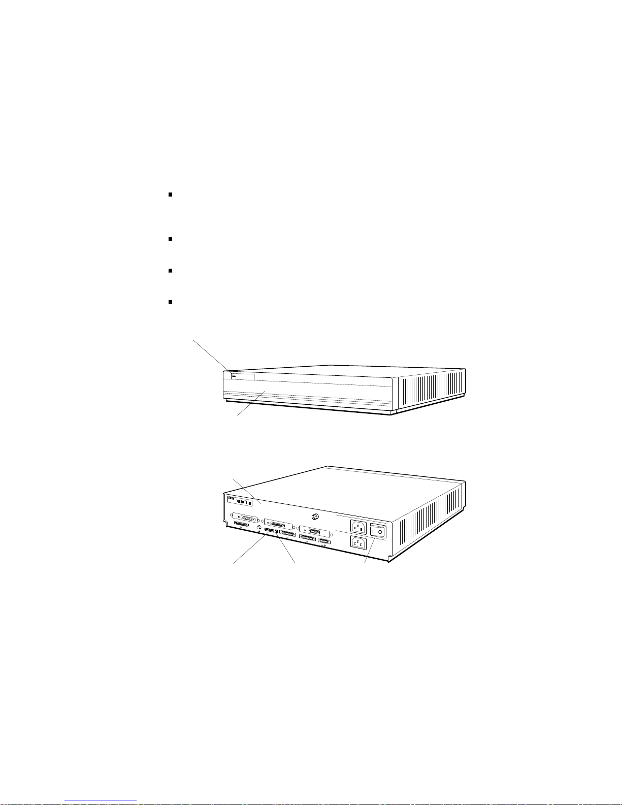
System Unit Controls and Indicators
The system unit controls and indicators, shown in Figure 1-3,
have the following uses:
The on/off switch turns the system on and off. Press down
the 0 on the switch to turn off the power. Press down the 1
on the switch to turn on the power.
The power indicator glows green when the power supply is
operating properly.
The diagnostic LEDs display binary error codes that
indicate test results.
The reset button initializes the system.
Power
supply
LED
DEC station 5000
Front view
Back view
d
i
g
i
t
a
l
0
Diagnostic
LEDs
PMAG-C
1
PMAZ-A
PMAD-A
3
Reset
button
V~100-120 A 3.0
V~220-240 A 1.7
2
V~100-120/220-240
A 7.9/4.2
Hz 50-60
W 359
2
On/off
switch
Figure 1-3. System controls and indicators
1–6 A Look at DECstation/DECsystem 5000 Model 200 Hardware
WSE2M003

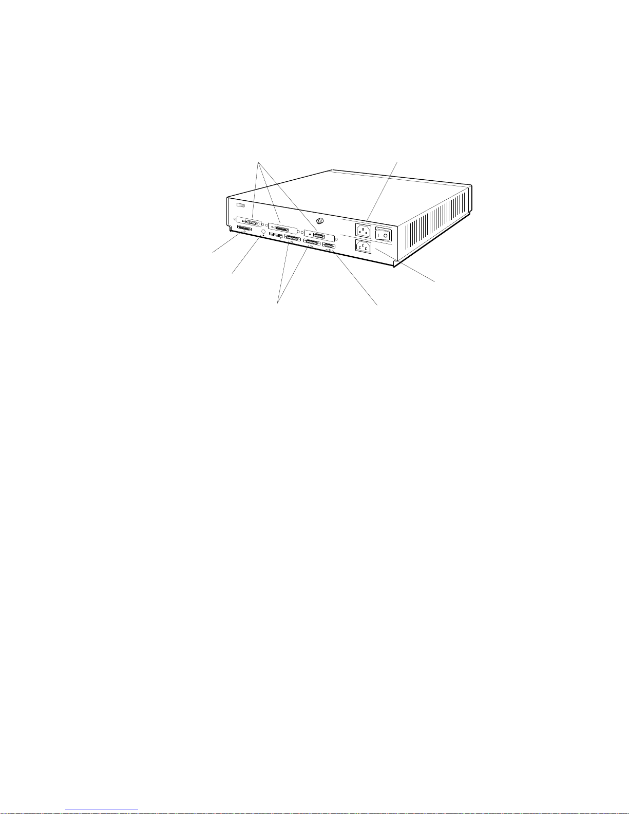
System Unit Connectors
The system unit connectors, shown in Figure 1-4, have the
following purposes:
The power connector connects the system unit power supply
and the system unit power cord.
The monitor-to-system-unit connector provides electric
power to the monitor power cord.
The ThinWire Ethernet connector links the system unit to
a ThinWire Ethernet.
The SCSI connector connects the base system SCSI
controller to a chain of external drives.
The keyboard-mouse connector links the system unit to the
keyboard-mouse cable.
The communications connectors provide printer, modem,
and console terminal connections. If there is a console
terminal, the terminal usually connects to the left
communications connector.
The option module connectors connect option modules to
external hardware. The number printed above each option
module connector is the slot number for any option module
in that slot.
A Look at DECstation/DECsystem 5000 Model 200 Hardware 1–7
SCSI
connector
Option module
connectors
d
i
g
i
t
a
l
0
PMAG-C
Monitor-to-system-unit
connector
1
PMAZ-A
PMAD-A
3
V~100-120 A 3.0
V~220-240 A 1.7
2
V~100-120/220-240
A 7.9/4.2
Hz 50-60
W 359
2
ThinWire
Ethernet
connector
Communications
connectors
Keyboard-mouse
connector
Figure 1-4. DECstation/DECsystem 5000 connectors
Power
connector
WSE2M004
1–8 A Look at DECstation/DECsystem 5000 Model 200 Hardware
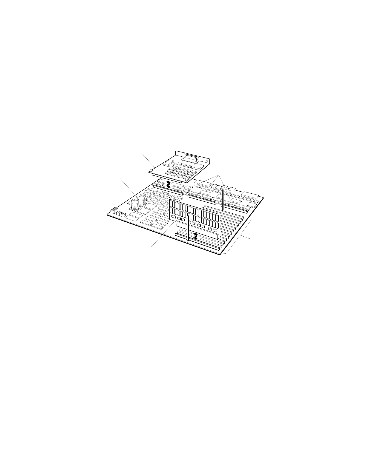
Hardware Options
The system module has slots for additional memory and
TURBOchannel option modules.
Figure 1-5 shows the location of memory and option module
expansion slots on the system module.
Option module
System
module
Memory module
Option module
expansion slots
Memory
module
expansion
slots
WSE2M005
Figure 1-5. Location of memory and expansion slots on the system
module
Additional Memory Modules
The system module has 15 expansion slots for additional
memory modules. Each memory slot can support one 8-Mbyte
memory module.
A Look at DECstation/DECsystem 5000 Model 200 Hardware 1–9

Optional TURBOchannel Modules
The three TURBOchannel expansion slots on the system unit
support a maximum of three option modules.
Any optional SCSI or Ethernet controller modules operate in
addition to the SCSI and ThickWire Ethernet controller built in
to the system module.
Drives
Each SCSI controller supports up to seven drives that connect
in a chain that attaches to the SCSI controller through the back
of the system unit.
Monitors and Terminals
The system supports different monitors, depending on the
graphics option modules that are in the system. Refer to the
TURBOchannel Maintenance Guide for a description of the
monitors that graphics option modules support.
The system can also display text on a VT320 terminal attached
to the communications connector on the left as you face the
back of the system unit.
Keyboard and Mouse
The system uses an LK201 keyboard and VSXXX-AA mouse
that connect to the back of the system unit through the
keyboard-mouse cable.
For Further Information
For further information about the hardware described in this
chapter, refer to later chapters that discuss the hardware in
which you are interested.
For further information about TURBOchannel option modules,
drives, or monitors, refer to the TURBOchannel Maintenance
Guide.
1–10 A Look at DECstation/DECsystem 5000 Model 200 Hardware

Service Operations
This chapter explains how to perform routine service
operations. It explains how to
Avoid electrostatic damage when handling components
Use an alternate terminal
Remove the system unit cover
Remove the front cover plate
Remove and replace the serial number plate
Install and remove terminators and loopback connectors
Enter console mode and operating mode
Use console command passwords
Boot the system software
Shut down the system software
2
Service Operations 2–1
 Loading...