

Page 1
Page 2
DECserver
200
Hardware
Installation/Owner's
Guide
Order
No.
EK-0200C-IN-001
October 1986
This guide
explains how to install the DECserver 200 and how to verify its
operation. The guide
also describes the DECserver 200 controls and
indicators. This document is intended for the hardware
installer and the
server manager:
Supersession/Update Information: This
is a
new
manual.
mamaala
Page 3
EK-D200C-IN-001
First Printing, October 1986
The information in this document
is subject to change without notice and should [lot be construed
as a commitment by Digital Equipment Corporation. Digital Equipment Corporation assumes no
responsibility for any errors that may appear in this document.
The software described in this document is furnished under a license and may only
be
used or
copied
in
accordance with the terms of such license.
No responsibility
is
assumed for the use or reliability of software on equipment that is not supplied
by Digital or its affiliated companies.
Copyright
© 1986 by Digital Equipment Corporation
All Rights Reserved.
Printed in
U.S.A.
The postage prepaid Reader's Comments form
on
the last page of this document requests the
user's critical evaluation to assist us in preparing future documentation.
The
following are trademarks of Digital Equipment Corporation:
DEC
MASSBUS
RT
DECconnect
MicroPDP-11
ThinWire
DECmate Micro/RSX
TOPS-10
DECnet MicroVAX
TOPS-20
DECserver
MicroVMS
ULTRIX
DECUS
PDP
UNIBUS
DECwriter
P/OS
VAX
DIBOL
Professional
VAXcluster
~D~DDmD
Rainbow
VAX/VMS
LA50
(LA 100, et al.)
RSTS
VMS
LN01
(LN03, et al.)
RSX
VT
LQP02 (LQP03, et al.)
RSX-11
M-PLUS
Work Processor
Bell is a trademark of Bell TeLephone Companies.
IBM 'is a registered trademark of International Business Machines Corporation.
PC/XT and Personal Computer AT are trademarks of International Business Machines
Corporation.
TEFLON
is
a trademark of Dupont.
This manual was produced by Networks and Communications Publications.
Page 4
Contents
Preface
1
Introduction to the DECserver 200
1.1 DECserver
200
Models
.......................................
'
.......
1-1
1.2
Functions
of
the
DECserver
200
....................................
1-2
1.2.1 DECserver 200/MC (DSRVB-Ax)
....................................
1-3
1.2.2 DEC
server
200/DL (DSRVB-Bx)
.....................
"
.............
1-4
1.3
Hardware
Installation
Overview.
. . . . . . . . . . . . . . . . . . . . . . . . . . . . . . . . .
..
1-5
1.3.1
Connecting
the
DECserver
200
to
the
Ethernet
Network. " ........
1-5
1.3.2
Connecting
Port
Devices
to
the
DECserver 200/MC
................
1-8,
1.3.3
Connecting
Port
Devices
to
the
DEC
server
200/DL
...............
1-10
1.4 DEC
server
200
Software
..........................................
1-12
2 Contents of Shipment
2.1
Number
of
Boxes
.......... ' ..........................................
2-1
2.2
Contents
ofthe
DECserver
200
Box
.................................
2-1
2.3
Contents
of
the
Accessories Box(es)
.................................
2-2
3 Site Preparation
3. 1 Arranging for
Software
InstallatiQn
................................
,
3-1
3.2 Placing
the
DEC
server
200
..........................................
3-2
3.2.1
Offices
..............................................................
3-2
3.2.2
Rack
Mount
.........................................................
3-2
3.2.3
Satellite
Equipment
Rooms
(SER)
....................................
3-2
3.3
Cable
Configuration
Rules
..........................................
3-3
3.4
Preinstallation
Checks
..............................................
3-5
Contents-1
Page 5
4 DECserver 200 Installation
4. 1
Introduction
..
. . . . . . . . . . . . . . . . . . . . . . . . . . . . . . . . . . . . . . . . . . . . . . . . . . . .
..
4-1
4.2
Verifying
the
Voltage Select
Switch
Setting . . . . . . . . . . . . . . . . . . . . . . .
..
4-1
4.3
Connecting
the
Transceiver
Cable
..................................
4-3
4.4
Before
Connecting
Power
...........................................
4-6
4.5
Connecting
Power
. . . . . . . . . . . . . . . . . . . . . . . . . . . . . . . . . . . . . . . . . . . . . . . .
..
4-7
4.6
Verifying
Operation
.................................................
4-8
4.7
Connecting
Device Cables
.......................
. . . . . . . . . . . . . . . . .
..
4-9
4.7.1
Connecting
Device Cables
to
the
DECserver 200/MC
...............
4-9
4.7.2
Connecting
Device Cables
to
the
DECserver 200/DL.
.............
4-11
4.8
Verifying System Installation
.....................................
4-16
5
What To Do if You Have Problems
5.1
Introduction
........................................................
5-1
5.2 Diagnosing Server
Problems
............................
. . . . . . . . . .
..
5-1
5.3
01
LED
Off
.........................................................
5-3
5.4
02
LED
Off
..........................................................
5-3
5.5
02
LED
Blinking
... " ..
, "
.,. " ..............................
'"
... , 5-4
5.5.1
Error
Messages
920
and
921
........................................
5-4
5.5.2
Error
Messages
922
and
923
.........................................
5-5
5.5.3
Error
Messages
930
and
931.
.........
'"
............................
5-5
5.5.4
Error
Message
932
..................................................
5-5
5.5.5
Error
Messages
941,942,
and
950
..................................
5-6
5.5.6
No Messages
on
Console
Terminal
. . . . . . . . . . . . . . . . . . . . . . . . . . . . . . . .
..
5-7
5.6
03
LED
Blinking
....................................................
5-8
5.6.1 Down-Line Load Starts,
Then
Fails
.................................
5-8
5.6.2
Down-Line Load
Does
Not
Start
............
"
.......................
5-8
A Controls and Indicators
A.1
Controls.
. . . . . . . . . . . . . . . . . . . . . . . . . . . . . . . . . . . . . . . . . . . . . . . . . . . . . . . . .
..
A-I
A.1.1
Software
Reset
Switch
(S
1)
. .
..
. . .
..
.. ..
. .
.. . .. .. .. . .. . ..
. .
.. . .. . ...
A-I
A.1.2 Voltage Select Switch
..............................................
A-I
A.1.3 Circuit Breaker
........................
'"
.,
.......... , .......
,. . ...
A-2
A.2 Status
Indicator
LEOs
..............................................
A-2
B Port Devices Supported by DECserver 200
C Ordering Information
C.l
DECserver
200
Hardware
Units
....................................
C-l
C.2 DECserver
200
Country
Kits
...................
" . . . . . . . .. . . . . . . .
..
C-1
C.3 DECserver
200
Accessories
........................................
C-2
Contents-2
Page 6
c.4
OEC OFFICE Cable (BC16E)
and
Adapters
.........
'"
......
....
...
C-3
C.S
Transceiver
Cables
.................................................
C-3
C.6
Oevice Cables
......................................................
C-4
D Cable Structure
E
F
0.1
0.2
0.3
0.3.1
0.3.2
0.3.3
0.3.4
0.3.5
0.4
0.5
0.5.1
0.5.2
0.5.3
0.5.4
0.5.5
0.5.6
0.5.7
0.5.8
D.5.9
DEC
server
200/MC Device
Connectors
01
throughJ8)
..
. . . . . . . .
..
0-1
Serial Line Circuit Standards
.......................................
0-2
Oevice Cables Used
With
DEC
server
200IMC . . . . . . . . . . . . . . . . . . . .
..
0-3
BC220
Shielded Null Modem Cable (Data Leads Only)
............
0-3
BC22E
or
BC22F Shielded Straight-Through Cable (Full-Modem)
..
D-4
BC22R Shielded Null Modem
Cable.
. . . . . . . . . . . . . . . . . . . . . . . . . . . . .
..
0-5
BC
170
Shielded Null Modem Cable. . . . . . . . . . . . . . . . . . . . . . . . . . . . . .
..
0-6
OECserver 200/MC
Port
Loopback
Connector.
. . . . . . . . . . . . . . . . . .
..
0-7
OECserver
200/0L
Device
Connector
01)
.........................
D-8
Oevice Cables
and
Adapters Used
With
OECserver
200/0L
. . . . . .
..
0-9
.
BC
16C
36-Conductor
Cable (Oata Leads
Only)
....................
0-9
H3101
36-pin
Loopback
Connector.
. . . . . . . . . . . . . . . . . . . . . . . . . . . .
..
0-10
H3102
36-pin
Cable
Coupler.
. . . . . . . . . . . . . . . . . . . . . . . . . . . . . . . . . . .
..
0-11
H3106
36-pin
to
50-pin Adapter . . . . . . . . . . . . . . . . . . . . . . . . . . . . . . . .
..
0-12
H3104
Cable
Concentrator.. . ..
.. . ..
..
.. . .. . ..
..
. .
..
.. . ..
. . .
..
....
0-13
H3103
MMJ
Loopback
Connector
.................................
D-14
BCI6E-xx
6-ConductorDEC
OFFICE Cable
......................
0-15
H8572
6-Pin Cable
Coupler
.......................................
0-16
H8571-xx
OEC423
to
RS-232-C
Passive Adapters
...............
0-17
OECserver 200 Specifications
E.1
Power
................................................................
E-l
E.2
Environment
...............................................
"
.........
E-l
E.2.1
Temperature
........................................................
E-l
E.2.2 Altitude
.............................................................
E-2
E.2.3 Relative
Humidity
...................................................
E-2
E.2.4 Physical Size
ofthe
DEC
server
200
...................................
E-2
E.2.5 Space Requirements
.................................................
E-2
Service Options
F.
1
Hardware
Services
...
. . . . . . . . . . . . . . . . . . . . . . . . . . . . . . . . . . . . . . . . . . . . .
..
F-l
F.1.1 Digital On-Site Service
..
. . . . . . . . . . . . . . . . . . . . . . . . . . . . . . . . . . . . . . . . . .
..
F-1
F.1.2 DEC
mailer
..........................................................
F-l
F.2 Installation Service. . . . . . . . . . . . . . . . . . . . . . . . . . . . . . . . . . . . . . . . . . . . . . . .
..
F-1
F.3
Software
Services
.....
. . . . . . . . . . . . . . . . . . . . . . . . . . . . . . . . . . . . . . . . . . . .
..
F-1
F.
3.1
Software
Product
Service Agreements
............
. . . . . . . . . . . . . . . .
..
F-l
F.3.2
Training
.............................................................
F-l
Contents-3
Page 7
G
Figures
Tables
Contents-4
Connecting to Etherjack
1-1
1-2
1-3
1-4
1-5
1~6
1-7
1-8
2-1
4-1
A-I
D-l
D-2
D-3
D-4
D-5
D-6
D-7
D-8
D-9
D-I0
D-l1
D-12
D-13
D-14
D-15
D-16
D-17
1-1
3-1
5-1
A-I
D-l
D-2
E-l
DECserver
200
(Models DSRVB-Ax
and
DSRVB-Bx) . . . . . . . . . . . . .
..
1-1
DECserver 200/MC . . . . . . . . . . . . . . . . . . . . . . . . . . . . . . . . . . . . . . . . . . . . . . . .
..
1-3
DECserver 200/DL . . . . . . . . . . . . . . . . . . . . . . . . . . . . . . . . . . . . . . . . . . . . . . . .
..
1-4
Standard
Ethernet
Coaxial Cable
Connection.
. . . . . . . . . . . . . . . . . . . .
..
1-6
Thin
Wire
Ethernet
Coaxial Cable
Connection
. . . . . . . . . . . . . . . . . . . .
..
1-7
DECserver
200IMC
Port
Device
Connections.
. . . . . . . . . . . . . . . . . . . .
..
1':'8
DECserver 200/DL
Port
Device
Connections
.....................
1-10
DEC
server
200/DL
Accessories...................
......... . .......
1-11
DEC
server
200
Shipping Box
Contents
.............................
2-1
DEC
server
200
Hardware
Verification
..............................
4-8
Controls
and
Indicators.
. . . . . . . . . . . . . . . . . . . . . . . . . . . . . . . . . . . . . . . . .
..
A-I
Pin
Numbers - DEC
server
200/MC Device
Connectors
01
through
J8). . . . . . . . . . . . . . . . . . . . . . . . . . . . . . . . . . . . . . . . . . . . . . . . . . . .
..
D-l
Pin
Assignments - BC22D Shielded Null
Modem
Cable
..
. . . . . . .
..
D-3
Pin
Assignments - BC22E
or
BC22F Shielded
Straight-Through
Cable
...............................................................
D-4
Pin
Assignments - BC22R
Shielded
Null
Modem
Cable.
..
. . . . . . .
..
D-5
Pin
Assignments -
BC
17D
Shielded
Null
Modem
Cable .. . . . . . . .
..
D-6
Wiring
Diagram
- DECserver 200/MC
Port
Loopback
Connector.
. . . . . . . . . . . . . . . . . . . . . . . . . . . . . . . . . . . . . . . . . . . . . . . . . . . . . . .
.. D-7
Pin
Numbers - DECserver 200/DL Device
Connector
01)
........
D-8
Wiring
Diagram -BC
16c
36-Conductor
Cable
..........
. . . . . . .
..
D-9
Wiring
Diagram
- H31 01
Loopback
Connector
.................
D-I0
Wiring
Diagram
- H31
02
36-
Pin
Cable
Coupler.
. . . . . . . . . . . . . . .
..
D-l1
Wiring
Diagram
- H31
06
Cable
Adapter.
. . . . . . . . . . . . . . . . . . . . . .
..
D-12
Wiring
Diagram
- H31
04
Cable
Concentrator
....
'.' . . . .. . . . . . .
..
D-13
Wiring
Diagram
- H31
03
MMJ
Loopb~ck
Connector
............
D-14
Wiring
Diagram -BC
16E-xx
Cable.
. . . . . . . . . . . . . . . . . . . . . . . . . . .
..
D-15
Wiring
Diagram -H8572
Cable
Coupler
.........................
D-16
WiringDiagram-H8571-AAdapter
............................
D-17
Wiring
Diagram -H8571-BAdapter
............................
D-17
Device Cables . . . . . . . . . . . . . . . . . . . . . . . . . . . . . . . . . . . . . . . . . . . . . . . . . . . . .
..
1-9
Maximum Cable Lengths . . . . . . . . . . . . . . . . . . . . . . . . . . . . . . . . .. . . . . . . . .
..
3-3
Status LEDs/Indications
.............................................
5-2
Status LEDs
...........................
,
..
.. . ..
....
.....
..
.. .
.. . ..
...
A-2
Circuit
Standards
...................................................
D-2
DEC
server
200/DL
Device
Connector
01)
Pin
Definitions
.........
D-8
DEC
server
200
Power
Ratings
......................................
E-l
Page 8
Preface
This guide explains
how
to
install
the
DECserver 200, models DSRVB-Ax and
DSRVB-Bx,
and
how
to verify their operation. The guide also tells
how
to
order
Digital
services
and
products that support
the
DEC
server 200.
The
only tool required for installation
is
a small flat-blade screwdriver.
You should keep this guide
with
your DECserver 200 unit.
Intended
Audience
• Server Manager
• Hardware Installer
How
to
Use
This
Guide
Before you install the DECserver 200, it
is
recommended that you read Chapters
1,
2,
and
3.
These chapters provide a functional overview
of
the DECserver 200 and -the
installation process, including important site preparation information. Chapter 4 provides procedures
to
install and verify
the
DEC
server 200.
If
problems occur during ver-
ification, refer
to
the
troubleshooting procedures
in
Chapter
5.
The appendixes offer
additional information that can be useful during installation.
Structure
of
This
Guide
This manual contains five chapters
and
seven appendixes,
as
follows:
Chapter
1
Chapter 2
Introduces the D ECserver 200 from a functional point
of
view and
describes the installation process and
the
software requirements.
Describes
the
contents
of
the
DEC
server 200 shipment and provides
instructions for getting help if the equipment
is
damaged.
Preface-1
Page 9
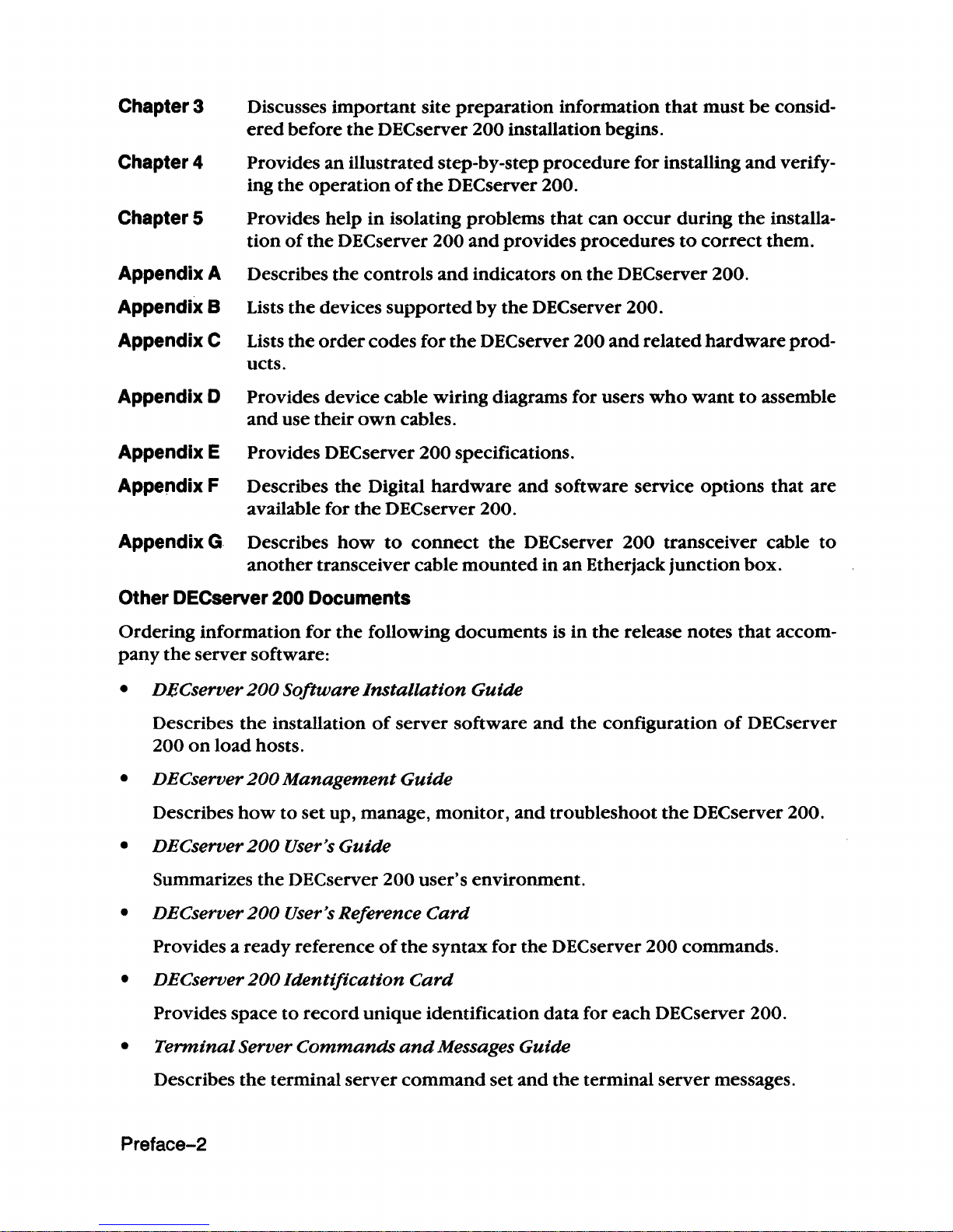
Chapter 3 Discusses
important
site preparation information
that
must
be
consid-
ered
before
the
DECserver
200
installation begins.
Chapter 4
Provides an illustrated step-by-step
procedure
for installing
and
verify-
ing the
operation
of
the
DEC
server 200.
Chapter 5 Provides help
in
isolating problems
that
can
occur
during
the
installa-
tion
of
the
DECserver 200
and
provides
procedures
to
correct
them.
Appendix A Describes the controls
and
indicators
on
the
DECserver 200.
Appendix B Lists
the
devices
supported
by
the
DEC
server 200.
Appendix C Lists
the
order
codes for
the
DEC
server 200
and
related
hardware
prod-
ucts.
Appendix
0 Provides device cable wiring diagrams for users
who
want
to
assemble
and
use
their
own
cables.
Appendix E
Provides
DEC
server
200
specifications.
Appendix F Describes
the
Digital
hardware
and
software service
options
that
are
available for
the
DEC
server 200.
Appendix G Describes
how
to
connect
the
DEC
server
200
transceiver cable
to
another
transceiver cable
mounted
in
an
Etherjack
junction
box.
Other DECserver 200 Documents
Ordering information
for
the
following documents is
in
the
release notes
that
accom-
pany
the
server software:
•
DeCserver
200
Software
Installation
Guide
Describes
the
installation
of
server
software
and
the
configuration
of
DECserver
200
on
load
hosts.
•
DEC
server
200
Management
Guide
Describes
how
to
set
up, manage,
monitor,
and
troubleshoot
the
DEC
server
200.
•
DEC
server
200
User's
Guide
Summarizes
the
DECserver
200
user's environment.
•
DEC
server
200
User's Reference
Card
Provides a ready reference
of
the
syntax for the DECserver 200 commands.
•
DEC
server
200
Identification
Card
Provides space
to
record
unique
identification data for each DECserver 200.
•
Terminal
Server
Commands
and
Messages
Guide
Describes
the
terminal
server
command
set
and
the
terminal server messages.
Preface-2
Page 10
•
LA
TPlusIVMS Service
Node
Management
Guide
Discusses
the
management
of
a V
AXNMS
or
a Micro
VMS
system
that
is
operating as
a service
node
in a
LA T network.
Associated Documents
•
nECserver
200
Technical
Manual
Describes
the
DECserver
200
hardware
and
module logic
and
the
self-test
and
ini-
tialize programs.
Preface-3
Page 11

Page 12
1
Introduction
to
the DECserver 200
Page 13

Page 14
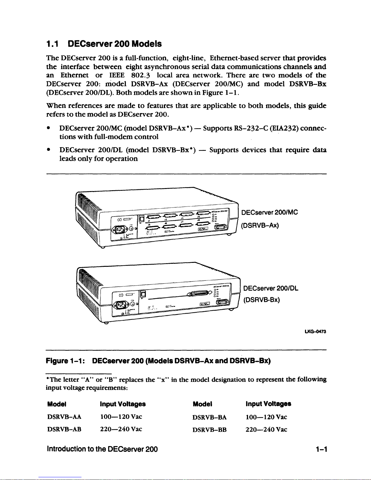
1.1
DECserver 200 Models
The
DEC
server
200
is a full-function, eight-line, Ethernet-based
server
that
provides
the
interface
between
eight
asynchronous
serial
data
communications
channels
and
an
Ethernet
or
IEEE
802.3
local area
network.
There
are
two
models
of
the
DEC
server
200:
model
DSRVB-Ax (DECserver 200/MC)
and
model
DSRVB-Bx
(DECserver
200IDL).
Both
models
are
shown
in
Figure
1-1.
When
references
are
made
to
features
that
are
applicable
to
both
models, this
guide
refers
to
the
model
as DEC
server
200.
•
DECserver 200/MC
(model
DSRVB-Ax*) - Supports
RS-232-C
(EIA232)
connec-
tions
with
full-modem
control
• DEC
server
200/DL
(model
DSRVB-Bx*) -
Supports
devices
that
require
data
leads
only
for
operation
DECserver 200/MC
(DSRVB-Ax)
DECserver
200/DL
(DSRVB-Bx)
Figure
1-1:
DECserver 200 (Models DSRVB-Ax and DSRVB-Bx)
LKG-0473
*The letter
"A"
or
"B"
replaces the
"x"
in the model designation
to
represent
the
following
input voltage requirements:
Model
DSRVB-AA
DSRV8-AB
Input Yoltages
lOO-120Vac
220-240Vac
Introduction to the OECserver
200
Model
DSRVB-BA
DSRVB-BB
Input Yoltages
lOO-120Vac
220-240Vac
1-1
Page 15
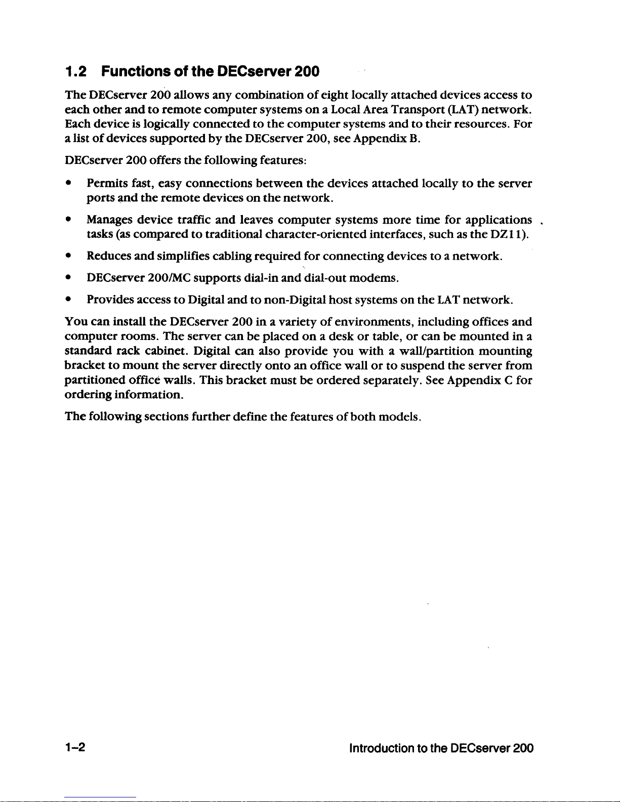
1.2 Functions of the DECserver 200
The
DECserver 200 allows any combination
of
eight locally attached devices access
to
each
other
and
to
remote
computer
systems
on
a Local Area Transport
(LAT)
network.
Each device is logically
connected
to
the
computer
systems
and
to
their resources. For
a list
of
devices
supported
by
the
DEC
server 200, see Appendix
B.
DECserver 200 offers
the
following features:
• Permits fast, easy connections
between
the
devices attached locally
to
the
server
ports
~nd
the
remote
devices
on
the
network.
• Manages device traffic
and
leaves
computer
systems
more
time for applications
tasks (as
compared
to
traditional character-oriented interfaces, such as
the
DZll).
• Reduces
and
Simplifies cabling required for connecting devices
to a network.
• DECserver 200IMC supports dial-in
and
dial-out modems.
• Provides access
to
Digital
and
to
non-Digital
host
systems
on
the
LAT
network.
You
can
install
the
DECserver 200
in
a variety
of
environments, including offices
and
computer
rooms.
The
server
can
be
placed
on
a desk
or
table,
or
can
be
mounted
in
a
standard rack cabinet. Digital
can
also
provide
you
with
a wall/partition
mounting
bracket
to
mount
the
server directly
onto
an
office wall
or
to
suspend
the
server from
partitioned office walls. This bracket must
be
ordered
separately. See Appendix C for
ordering information.
The
following sections
further
define the features
of
both
models.
1-2
Introduction to the DECserver 200
Page 16
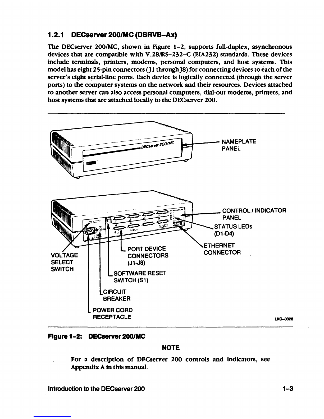
1.2.1 DECserver 200/MC (DSRVB-Ax)
The
DECserver
2001MC,
shown
in
Figure
1-2,
supports full-duplex, asynchronous
devices
that
are compatible
with
V.28/RS-232-C (EIA232) standar.ds. These devices
include terminals, printers, modems, personal computers, and host systems. This
model has eight 25-pin connectors
(J
1 throughJ8) for connecting devices
to
each
of
the
server's eight serial-line ports. Each device
is
logically connected (through
the
server
ports)
to
the
computer systems
on
the network
and
their resources. Devices attached
to
another
server can also access personal computers, dial-out modems, printers,
and
host systems that are attached locally
to
the
DECserver 200.
11-.......1-----
NAMEPLATE
PANEL
~~
__
-
CONTROL
I INDICATOR
PANEL
PORT DEVICE
CONNECTORS
(J1-J8)
SOFTWARE RESET
SWITCH (S1)
CIRCUIT
BREAKER
POWER
CORD
RECEPTACLE
Figure
1-2:
DECserver 200/MC
NOTE
STATUS LEOs
(01-04)
For a description
of
DEC
server 200 controls
and
indicators, see
Appendix A
in
this manual.
Introduction to the DECserver
200
1-3
Page 17
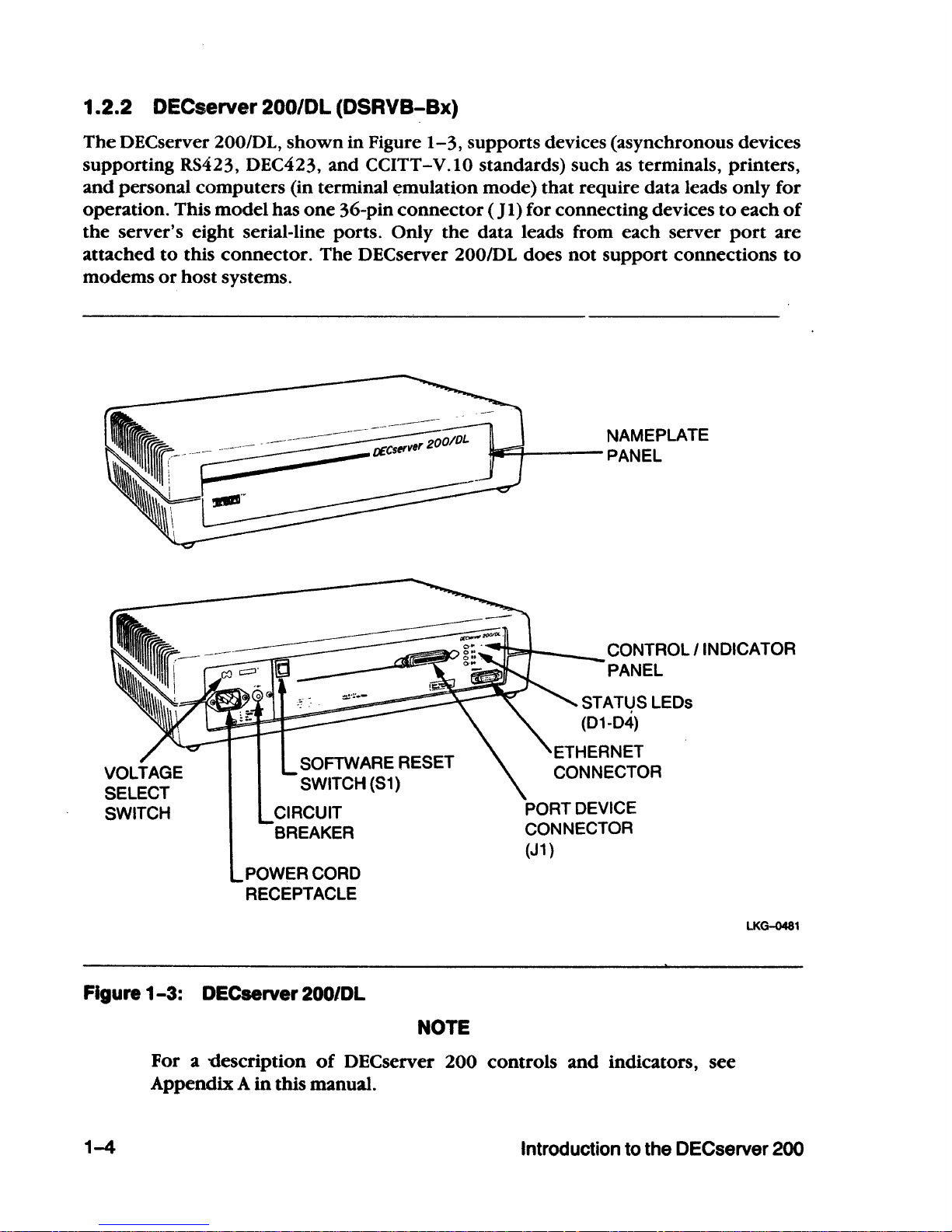
1.2.2 OeCserver 200/DL (DSRVB-Bx)
The
DECserver 200/DL,
shown
in
Figure
1-3,
supports devices (asynchronous devices
supporting RS423, DEC423, and
CCITT-V.IO standards) such as terminals, printers,
and
personal computers (in terminal
~mulation
mode) that require data leads only for
operation. This
model
has
one
36-pin
connector
( J
I)
for connecting devices
to
each
of
the
server's eight serial-line ports. Only
the
data leads from each server
port
are
attached
to
this
connector.
The
DEC
server 200/DL does
not
support
connections
to
modems
or
host
systems.
SOFTWARE RESET
SWITCH
(51)
CIRCUIT
BREAKER
POWER CORD
RECEPTACLE
NAMEPLATE
w:;;....r----
PANEL
CONTROL I INDICATOR
PANEL
PORT DEVICE
CONNECTOR
(J1
)
LKG-0481
Figure
1-3:
DECserver 200/DL
1-4
NOTE
For a 'Clescription
of
DECserver 200 controls
and
indicators, see
Appendix A
in
this manual.
Introduction
to
the DECserver 200
Page 18
1.3 Hardware Installation Overview
Installing
the
DEC
server
200
hardware
consists
of
first connecting
the
server
to
the
Ethernet
network,
then
verifying
the
hardware
installation.
The
device cables are con-
nected
to
the
server after
the
hardware
installation
is
verified.
The
following sections
provide
an
overview
of
the
methods
used
to
complete
the
connections.
NOTE
The
DEC
server
200
is considered operational
when
the
server hard-
ware
is successfully installed,
and
the system installation verification
procedure
is
performed
on
one
DEC
server 200 unit.
The
system com-
prises
the
installed
DEC
server 200 hardware
with
the
DEC
server 200
server software running
on
the
hardware unit. See
the
appropriate
DEC
server 200 Software Installation Guide for details about
the
sys-
tem
verification
procedure.
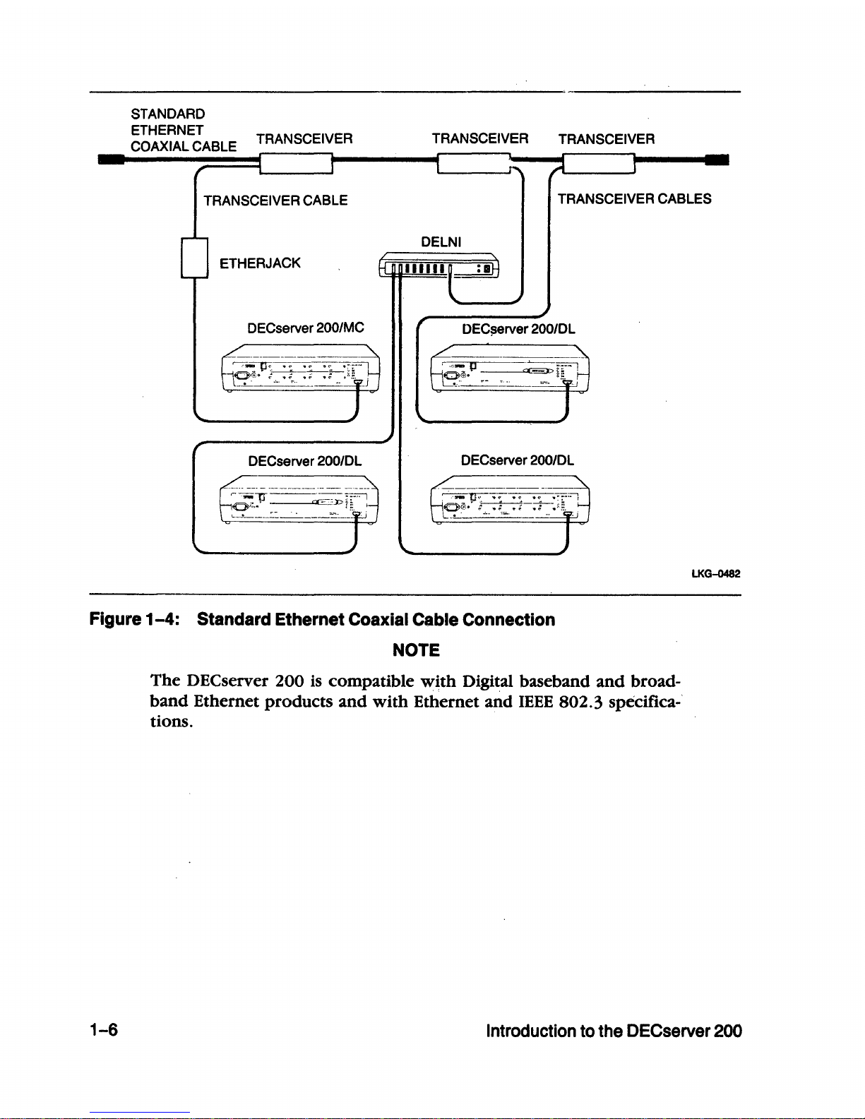
1.3. 1 Connecting the OECserver 200
to
the Ethernet Network
A transceiver cable connects
the
server
to
the Ethernet
network
(see Figures
1-4
and
1-5).
The
transceiver cable
can
be
connected
to
any
of
the
following:
• Another transceiver cable section. This cable can
be
secured in an Etherjack junc-
tion
box.
• A
DELNI
Local
Network
Interconnect.
• A transceiver
on
a standard Ethernet coaxial cable for Digital baseband networks
or
a DECOM for Digital
broadband
networks.
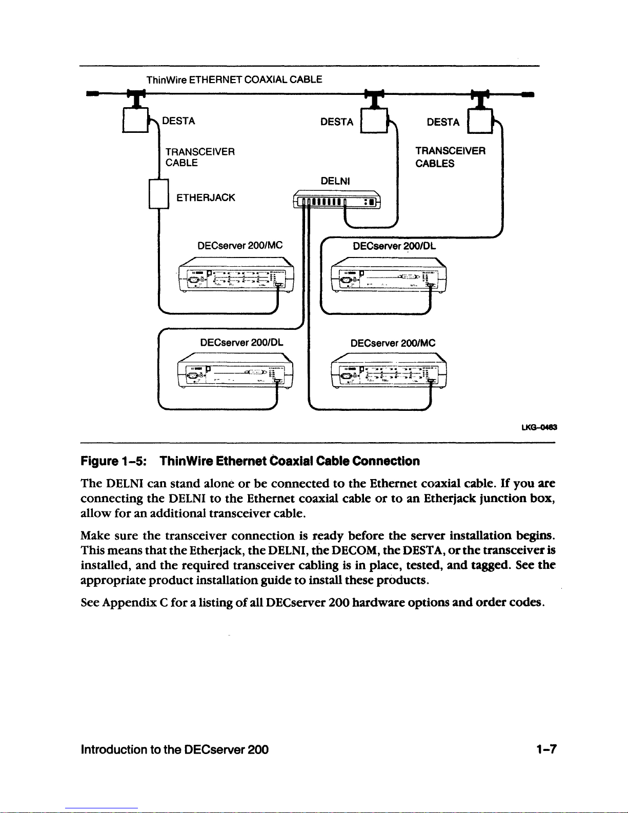
• A ThinWire Ethernet Station Adapter
(DESTA)
on
a ThinWire Ethernet coaxial
cable (see Figure
1-5).
• A standard rack cabinet
in
a Satellite Equipment Room
(SER)
for
DEC
connect
sys-
tems.
See
the
DECconnect
Planning
and
Configuration
Guide
for installing
the
DECserver 200 in DECconnect systems.
Introduction to the DECserver 200
1-5
Page 19
STANDARD
ETHERNET
COAXIAL CABLE TRANSCEIVER
TRANSCEIVER
TRANSCEIVER
TRANSCEIVER
CABLE
TRANSCEIVER CABLES
DELNI
ETHERJACK
DECserver
200/MC
DEC$erver 200/DL
DECserver 200IDL
DECserver 200/DL
Figure
1-4:
Standard Ethernet Coaxial Cable Connection
NOTE
The
DECserver
200
is
compatible
with
Digital baseband
and
broad-
band
Ethernet
products
and
with
Ethernet
and
IEEE
802.3
specifica-'
tions.
LKG-0482
1-6
Introduction
to
the DECserver
200
Page 20
ThinWire ETHERNET COAXIAL CABLE
DESTA
DESTA
TRANSCEIVER
CABLE
ETHERJACK
DECserver
200/MC
DECserver 200/DL
DELNI
TRANSCEIVER
CABLES
DECserver 200/DL
DECserver 200/MC
Figure
1-5:
ThinWire Ethernet Coaxial Cable Connection
LKG-0483
The
DELNI
can
stand
alone
or
be
connected
to
the
Ethernet coaxial cable.
If
you
are
connecting
the
DELNI
to
the
Ethernet coaxial cable
or
to
an
Etherjack junction box,
allow for
an
additional transceiver cable.
Make sure
the
transceiver
connection
is ready before
the
server installation begins.
This means
that
the
Etherjack,
the
DELNI,
the
DECOM,
the
DEST
A,
or
the
transceiver is
installed,
and
the
required transceiver cabling is
in
place, tested,
and
tagged. See
the
appropriate
product
installation guide
to
install these products.
See Appendix C
for
a listing
of
all DECserver
200
hardware options
and
order
codes.
Introduction
to
the DECserver 200 1-7
Page 21
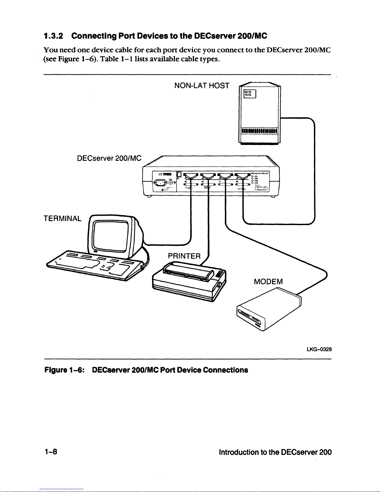
1.3.2 Connecting Port Devices
to
the DECserver
200/MC
You
need
one
device cable for each
port
device you
connect
to
the
DECserver 200/MC
(see Figure
1-6).
Table
I-lUsts
available cable types.
NON-LAT HOST
111.11111111111
DECserver 200/MC
TERMINAL
LKG-0328
Figure
1-6:
D,ECserver 200/MC Port Device Connections
1-8
Introduction
to
the DECserver
200
Page 22
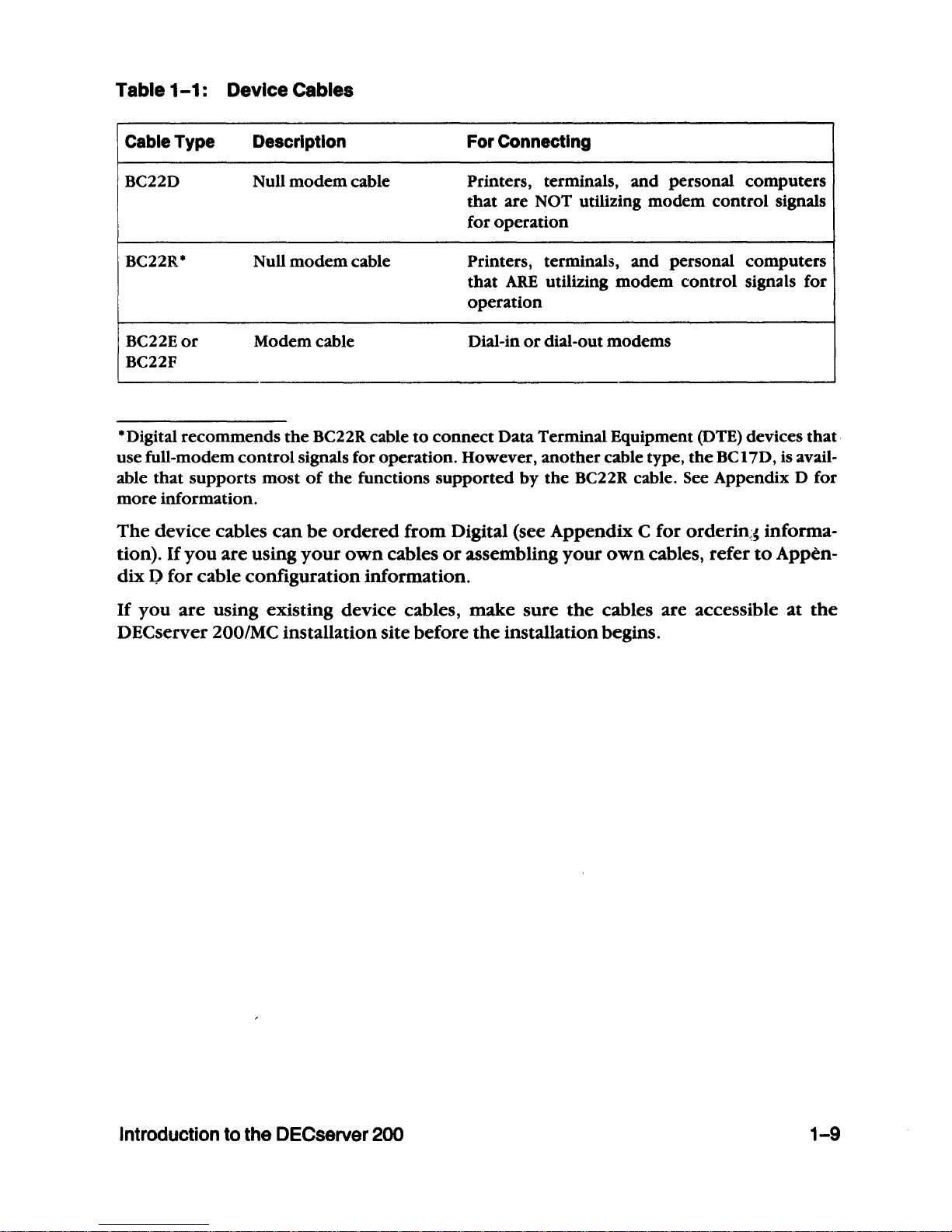
Table
1-1:
Device Cables
Cable Type Description For Connecting
BC22D Null
modem
cable
Printers, terminals,
and
personal computers
that
are NOT utilizing modem control signals
for operation
BC22R*
Null
modem
cable Printers, terminals,
and
personal computers
that
ARE
utilizing
modem
control signals for
operation
BC22Eor Modem cable Dial-in
or
dial-out modems
BC22F
*Digital recommends
the
BC22R cable
to
connect
Data Terminal Equipment (DTE) devices that·
use full-modem
control
signals for operation. However, another cable type,
the
BC
17D, is avail-
able
that
supports
most
of
the functions
supported
by
the
BC22R cable. See Appendix D for
more information.
The
device cables
can
be
ordered
from Digital (see Appendix C for
orderin.:~
informa-
tion). If
you
are using
your
own
cables
or
assembling
your
own
cables, refer
to
Appen-
dix P for cable configuration information.
If
you
are using existing device cables, make sure
the
cables are accessible
at
the
DEC
server 200/MC installation site before
the
installation begins.
Introduction to the DECserver
200
1-9
Page 23
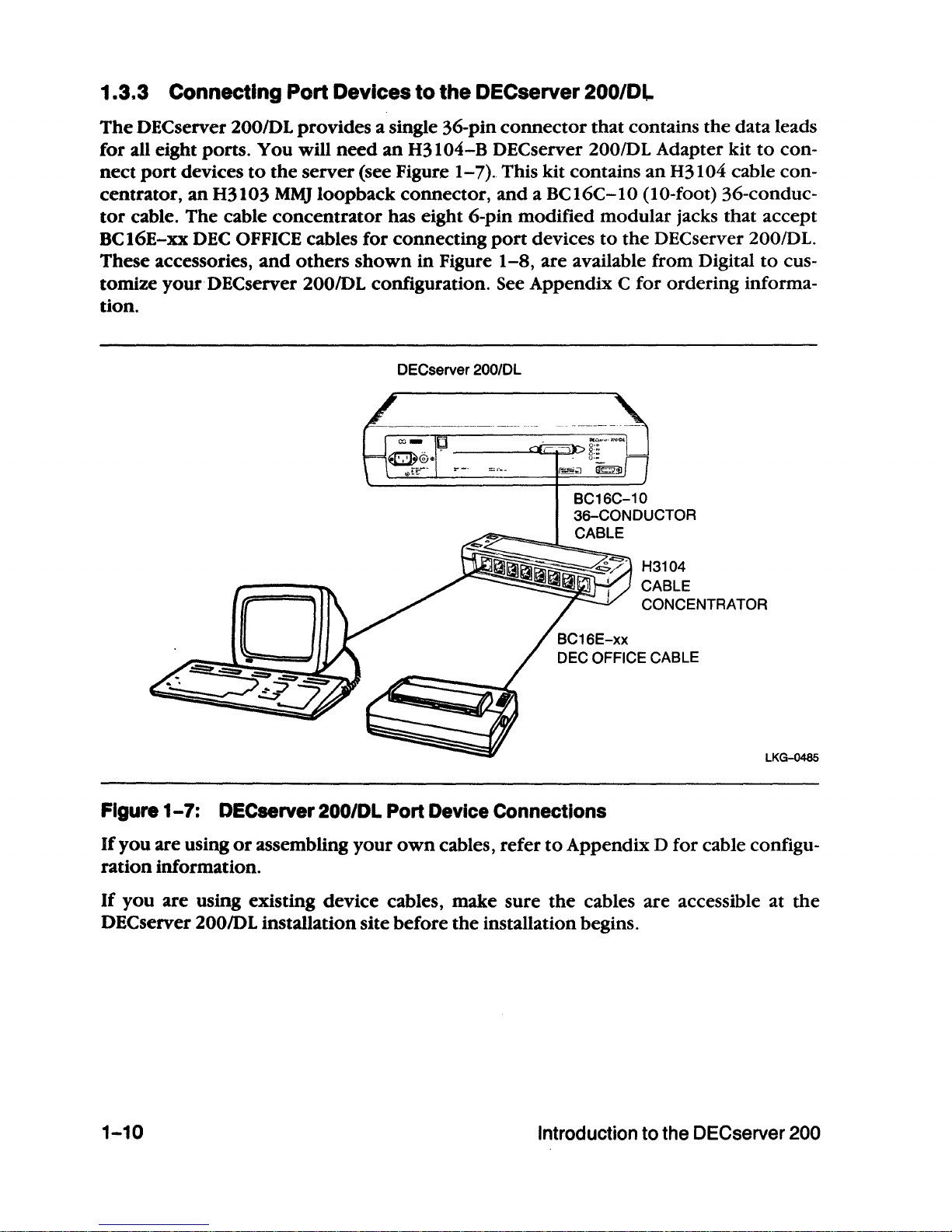
1.3.3 Connecting Port Devices
to
the DECserver 200/Dl-
The
OECserver
200/0L
provides a single 36-pin
connector
that contains the data leads
for all eight ports.
You will
need
an
H3104-B DECserver
200/0L
Adapter kit
to
con-
nect
port
devices
to
the
server (see Figure
1-7)
..
This kit contains
an
H3104 cable con-
centrator,
an
H3103
MMJ
loopback connector,
and
a BC16C-IO (10-foot) 36-conduc-
tor
cable. The cable
concentrator
has eight 6-pin modified modular jacks that accept
BCI6E-xx
DEC
OFFICE cables for connecting
port
devices
to
the
DECserver
200/DL.
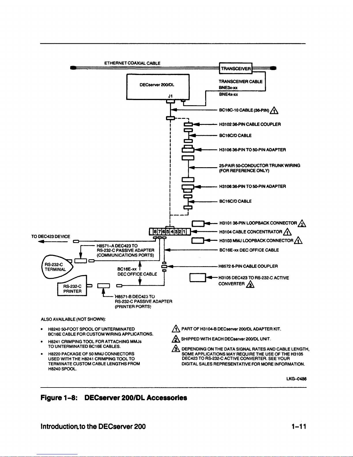
These accessories,
and
others
shown
in
Figure
1-8,
are available from Digital
to
cus-
tomize
your
DEC
server 200/DL configuration. See Appendix C for ordering informa-
tion.
DECserver 200/DL
BC16E-xx
H3104
CABLE
CONCENTRATOR
DEC OFFICE CABLE
LKG-0485
Figure
1-7:
DECserver 200/DL Port Device Connections
If
you
are using
or
assembling
your
own
cables, refer
to
Appendix D for cable configu-
ration
information.
If
you
are using existing device cables, make sure
the
cables are accessible at
the
OECserver 200lOL installation site before
the
installation begins.
1-10
Introduction
to
the DECserver 200
Page 24
ETHERNET
COAXIAL
CABLE
DECserver
200IDL
.....
r-------
BC16C-10CABLE
(36-PIN)
&
--.,
C
.......
--
H3102
36-PIN
CABLE
COUPLER
~
BC18C/D
CABLE
a
..
H310636-PIN T05().PIN
ADAPTER
~
25-PAIR
SO-CONDUCTOR
TRUNK
WIRING
6
(FOR
REFERENCE
ONLy)
9"4
H3106
36-PIN
TO
5().PIN
ADAPTER
~
BC16C1OCABLf
r--.J
I c:::J4--
H3101
36-PIN
LOOPBACK
CONNECTOR
&
Ile17160041!1211
I I
~
H3104
CABLE
CONCENTRATOR
&
TO
DEC423
DEVICE
I:!II
~
/),.
4 c::J
::r
c:::J4--.
H3103MMJLOOPBACKCONNECTORl.,U
J:
H8571-A DEC423
TO
RS-232·C
PASSIVE
ADAPTER
BC16E·xx
DEC
OFFICE
CABLE
(COMMUNICATIONS
PORTS)
c::J
...
H8572
6-PIN
CABLE
COUPLER
~H3105
DEC423
TO
RS·232-C
ACTIVE
~
·H8571·B
DEC423
TO
RS-232·C
PASSIVE
ADAPTER
(PRINTER
PORTS}
CONVERTER&,
ALSO
AVAILABLE
(NOT
SHOWN):
•
H8240
50-FOOT
SPOOL
OF
UNTERMINATED
BC16E
CABLE
FOR
CUSTOM
WIRING
APPLICATIONS.
•
H8241
CRIMPING
TOOL
FOR
ATTACHING
MMJs
TO
UNTERMINATED
BC16E
CABLES.
•
H8220
PACKAGE
OF
50
MMJ
CONNECTORS
USED
WITH
THE
H8241
CRIMPING
TOOL
TO
TERMINATE
CUSTOM
CABLE
LENGTHS
FROM
H8240
SPOOL.
.&
PART
OF
H3104-B
DECserver
200/DL
ADAPTER
KIT.
&
SHIPPED
WITH
EACH
DECserver
200/DL
UNIT.
&
DEPENDING
ON
THE
DATA
SIGNAL
RATES
AND
CABLE
LENGTH,
SOME
APPLICATIONS
MAY
REQUIRE
THE
USE
OF
THE
H3105
DEC423
TO
RS-232·C
ACTIVE
CONVERTER.
SEE
YOUR
DIGITAL
SALES
REPRESENTATIVE
FOR
MORE
INFORMATION.
LKG-0486
Figure
1-8:
DECserver 200/DL Accessories
Introduction.
to
the DECserver
200
1-11
Page 25
1.4 OECserver 200 Software
The
basic
software
required
for
installing
and
operating
the
DEC
server
200
follows:
• DECserver
200
distribution
software
- Installed
on
each
DECserver
200
load
host
• DECnet Phase IV
software
- Installed
on
each
DECserver
200
load
host
(not
required
for
UL
TRIX systems)
•
LA
T service
node
software
- Installed
on
all
LA
T service
nodes
that
communicate
with
DEC
server
200
devices
You
must install
the
distribution
software
on a load
host
that
runs DECnet Phase
IV
software.
The
distribution
software
includes a
server
image file that is
down-line
loaded
to
DECserver 200s.
The
load
host
down-line
loads
the
server
image
whenever
required,
and
provides
the
server
image
to
any
number
of
servers.
The
server
image,
running
on
the
DECserver 200,
constitutes
the
server
software
that enables
the
server
to
perform
its functions.
The
LA
T service
node
software
supports
the
LA T architecture
and
must
be
installed
on
each
service node.
The
packaging
of
the
LA
T service
node
software
depends
on
the
operating
system
running
on
the
service node:
• V
AXIVMS
or
Micro
VMS
operating
system (Versions
4.2
through
4.5) -
LA
T service
node
software
(LATplusIVMS)
is
contained
in
the
DECserver
200
software
kit. For
later versions,
the
LAT
service
node
software
is
part
of
the
operating
system.
•
UL
TRIX-32/32m
operating
system -
LAT
service
node
software
is
included
with
the
operating
system.
• RSX-IIM-PLUS
or
Micro/RSX
operating
system -LAT
service
node
software
is
included
with
DECnet-RSX software.
•
TOPS-IO
or
TOPS-20
operating
system -LAT
service
node
software
is
included
with
the
operating
system. .
All
software
must
be
installed
and
verified
before
you
can
operate
the
server.
For
more
information,
see
the
DECserver
200
Software
Product
Description
that
applies
to
the
specific
operating
system.
1-12
Introduction
to
the
DECserver
200
Page 26

2
Contents
of
Shipment
Page 27

Page 28
2.1
Number
of
Boxes
A single
DEC
server 200
shipment
consists
of
one
or
more
boxes, depending
on
the
optional equipment
ordered.
Be sure
you
received all
your
ordered
equipment. Check
each item for damage.
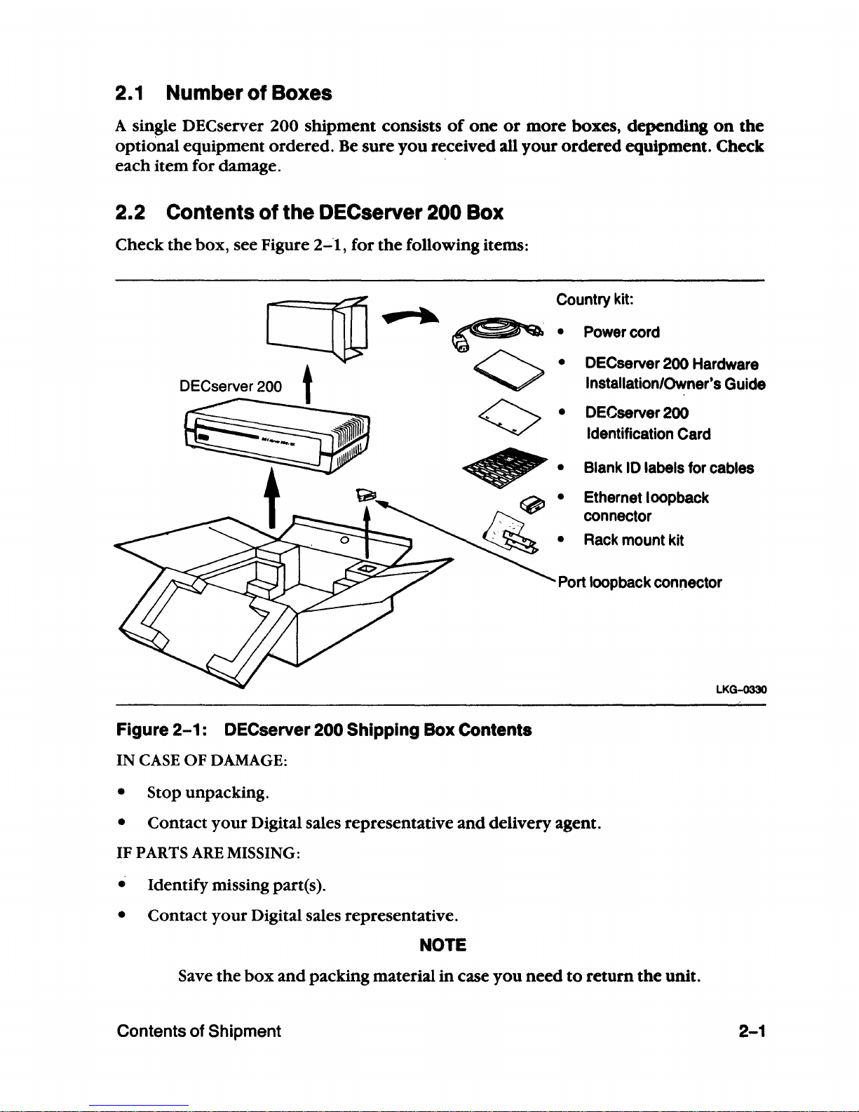
2.2 Contents
of
the DECserver
200
Box
Check
the
box, see Figure
2-1,
for
the
following items:
c:no"
DECserver 200 t
Figure
2-1:
DECserver 200 Shipping Box Contents
IN
CASE
OF
DAMAGE:
• Stop unpacking.
Country
kit:
Power
cord
OECserver
200
Hardware
Installation/Owner's Guide
OECserver
200
Identification
Card
• Blank
10
labels for cables
Ethernet loopback
connector
•
Rack
mount kit
Port
loop
back connector
LKG-033O
• Contact
your
Digital sales representative
and
delivery agent.
IF
PARTS
ARE
MISSING:
• Identify missing part(s).
• Contact
your
Digital sales representative.
NOTE
Save
the
box
and
packing material
in
case
you
need
to
return
the
unit.
Contents of Shipment
2-1
Page 29
2.3 Contents
of
the Accessories Box(es)
~
The
number
of
boxes
and
their oonteJtts depends
on
the
options
you
ordered.
Open
the
accessories box( es)
and
check
the
contents against
the
ordered
items
that
are listed
in
your
bill
of
materials.
IN
CASE
OF
DAMAGE:
• Stop unpacking.
• Contact
your
Digital sales representative
and
delivery agent.
IF
PARTS
ARE
MISSING:
• Identify missing part(s).
• Contact
your
Digital sales representative.
NOTE
Save
the
box(es)
and
packing material
in
case you need
to
return
items.
If
you received
an
Etherjack junction
box
kit, install it
now
by
following the· installa-
tion
instructions
provided
with
the
kit.
If
you
received a wall/partition mounting bracket kit, install it
now
by
following
the
installation instructions
provided
with
the
kit.
2-2
Contents
of
Shipment
Page 30

3
Site Preparation
Page 31

Page 32

3.1
Arranging
for Software Installation
1 Locate
the
server's serial num-
ber
and
the
Ethernet address
on
the
server's control/indica-
tor
panel.
MODEL: DSRVB-A
SN:
111111111111111111111111111111111111111111111111111111111111
SERIAL
• A G 6 2 0
00
1 9 9 •
NUMBER
2 Locate
the
DEC
server 200 Ter-
minal
Server Identification
Card you received
with
the
server. Copy
the
following
information in
the
spaces pro-
vided
on
the
identification
card:
a.
The server's serial number
b. The server's
address
Ethernet
c. The location
of
the server
(for example, office num-
ber, building, floor)
d.
Your name
and
the
date
of
the
installation
c:::::::::.
c:::::::::::::l
cc:::==»
c:::::::::::::l
~~::-IOO/"C
.It
••
•• ••
0-01
~
~
C:=:.
-==-
g:!!-
"....,.....::-..:::...
~~.J
co:;)
ETHERNET
ADDRESS
LKG-0331
DECserver
200
Identification
Card
Th.
",rl.1
num""r
.nd
Eth.rn.t
.dd
....
unlqu.ly Id.ntlfy your DECKrv.r 200 hard·
ware unh. Please copy the Infurmatlon from your hardware unit onco this card.
Include your name, the date
of
Installation. and the location (for example. omce num·
bc:r.
building. flonr)
of
th.
hardware: unit. You should
th.n
Ilv.
this card
to
your sys·
tem/network manager at the same
lime
as
you hand over the loftware carton.
Serl.1
number
Eth.rnet
addr
...
Location
Your
name
M.
UN'T'O
D.t
• ...8.-,JS,A
LKG-0487
3 Give
the
Identification Card and any software you received
to
the system/network
manager (the
person
responsible for software installation).
Ask
to
be
notified
when
the
distribution software is installed
on
the
load host(s) and
when
the
DECserver
200
is configured
in
the load host database,
if
required by the load host(s).
Continue
with
the
procedures through Section 4.4
of
this manual.
Site
Preparation 3-1
Page 33

3.2 Placing the DECserver 200
The
server can-be
placed
in
various locations, including offices
and
computer
rooms, as
long
as
the
environmental requirements are met. See Appendix
E,
DEC
server 200 Spec-
ifications.
3.2.1 Offices
Allow 15 centimeters (6 inches)
of
airspace
around
the
server air vents,
and
place
the
server
on
a desk
or
table
that
is at least 45 centimeters (18 inches) above
the
floor. This
allows adequate ventilation
for
cooling fans
and
reduces
exposure
to
excess dust from
foot
traffic.
NOTE
A wall/partition
mounting
bracket
ki.t
is also available from Digital
that
allows you
to
mount
the
server directly
to
a wall
or
to
suspend it from
partitioned
office walls. Installation instructions are
provided
with
the
kit (see Appendix C for ordering information).
3.2.2 Rack Mount
The
server
can
be rack
mounted
in
a standard rack cabinet.
To
install, refer
to
the
instal-
lation instructions
provided
with
the
rack
mount
kit.
3.2.3
Satellite Equipment Rooms (SER)
The
SER
is a component
o'fDigital's DECconnect System.
It
provides
a central location
for
communications devices (such as DECserver 200s)
that
connect
ThinWire Ethernet
and
twisted-pair cable
to a standard
Ethernet
network.
The
SER
can
also be configured
as
the
center
of
a stand-alone
network,
and
provide
a base
from
which
to
expand
as net-
work
requirements increase.
If
you
are
installing
the
DEC
server 200 in such
an
envi-
ronment,
or
as
part
of
a DECconnect System installation, refer
to
the
DECconnect Sys-
tem
Installation
and
Verification Guide.
3-2
Site Preparation
Page 34

3.3 Cable Configuration Rules
Ensure
that
the
transceiver
cables,
the
device
cables,
and
the
server
power
cable
do
not
exceed
the
maximum
lengths
described
in
Table
3-1
and
in
the
configuration
rules
below.
Table
3-1:
Maximum Cable Lengths
Maximum Cable
From
To
Length
Cable Type
Transceiver
Server
50 m (164 ft)
BNE3X-xx· Transceiver cable
See rules 1 and 2
Transceiver
Server
12. 5 m (41ft) BNE4X-xx· Office transceiver
See rules 1 and 2
cable
Device
Server
See
rule 3
Depends
on
specific device
(see Appendix
D)
Wall outlet
Server
1.8 m (6 ft) Server
power
cable (included
in
DSRVB-xx country kit)
Basic
configuration
rules:
1
Maximum
length
for
the
transceiver
cable
cannot
exceed
50
meters
(164
feet).
This
maximum
length
can
be
reduced
due
to
the
internal
cabling
equivalency
of a device
(such
as a DELNI)
that
is
connected
between
the
server
and
the
transceiver,
or
due
to
the
use
of
office
transceiver
cable:
•
Cabling
equivalency
is a
measure
of
the
internal
timing
delay
of a device,
expressed
in
meters
of
transceiver
cable.
This
cabling
equivalency
must
be
sub-
tracted
from
the
50-meter
maximum.
For
example,
if a device
has
as-meter
cabling
equivalency,
then
its
maximum
allowable
transceiver
cable
length
is
(50
m - 5
m)
or
45
meters.
•
Office
transceiver
cable
(BNE4x-xx),
due
to
its
smaller
diameter,
has a signal
loss
that
is
four
times
that
of
the
(BNE3x-xx)
transceiver
cable.
Therefore,
if
office
transceiver
cable
is
used,
the
maximum
transceiver
cable
distance
must
be
divided
by
4.
This
means-
the
maximum
office
transceiver
cable
length
allowed
is
12.5
meters
* .
*BNE3x-xx transceiver cable and BNE4x-xx office transceiver cable can be interconnected.
However, the cable attenuation (signal loss) for
the
office transceiver cable
is
greater than that
of
BNE3x-xx transceiver cable by a factor
of
four. For example, 2 meters,
6.6
feet,
of
office trans-
ceiver cable
is
electrically equivalent
to
8 meters, 26.2 feet, ofBNE3x-xx transceiver cable.
Site Preparations
3-3
Page 35

If
the
configuration includes a device
and
the
device has
any
internal cabling equiv-
alency' this
should
be
subtracted from
the
50-meter maximum before dividing
by
4. For example,
if
a device has a 10-meter cabling equivalency
and
is
attached
to
its
transceiver using office transceiver cable,
then
the
maximum allowable transceiver
length
is
(50 m - 10 m)/4
or
10 meters.
2
When
connecting
the
server
to
a configuration
that
includes a DELNI, allow
5-meters cabling equivalency loss for
the
DELNI.
3 Maximum allowable lengths for device cables should
not
exceed
guidelines
set
bv
RS-232-C
(EIA232) specifications.
3-4
Site Preparation_
Page 36

3.4 Preinstallation Checks
Before beginning
the
server
installation, use
the
following checklists
to
ensure
that
site
preparation
is
complete:
Hardware
o
The
appropriate
baseband
or
broadband
network
interface (for example,
an
Etherjack
junction
box,
a DELNI, a DECOM, a DEST
A,
or
Ethernet transceiver)
is
installed,
and
the
required
transceiver cabling is
in
place, tested,
and
tagged.
If
the
device is
not
installed,
ensure
that
arrangements for
the
installation are
made
before
the
server
installation begins.
o
The
arrangements
were
made
to
connect
the
server's
transceiver cable
to
the
appropriate
baseband
or
broadband
network
interface.
o
The
wall/partition
mounting
bracket
kit
or
rack
mount
kit
is
installed (if required)
as described
in
the
kit
documentation.
o
The
transceiver cables are available in
the
appropriate
lengths.
o
The
device cables are available in
the
appropriate
lengths
or
existing device cables
you
plan
to
use are available at
the
server
installation site.
o
If
you
are installing a DECserver 200/DL,
be
sure
that
any additional accessories
required
to
support
your
configuration are available at
the
server installation site.
o
The
devices (terminals, printers, personal
computers,
modems, hosts) are
ready
to
be
connected.
D At least
one
device
with a keyboard
(such as a terminal
or a personal
computer
in
terminal
emulation
mode)
is available for installation troubleshooting,
if
necessary,
and
for
system installation verification (as described
in
the
appropriate
DEC server
200
Software Installation Guide).
Software
o
The
DEC
server
200
Identification Card was filled
out
(as described
in
Section 3.1)
and
given
to
the
system/network
manager.
o
The
system/network
manager installed
or
will install
the
distribution
software
on
the
load
host(s).
o DECnet (Phase IV) is installed
and
r~nning
on
the
load
host(s). (This
does
not
apply
to
ULTRIX
load
hosts.)
.0
The
system/network
manager installed
or
will install
the
LA
T service
node
soft-
ware
(if required).
Site Preparation
3-5
Page 37

Suitable Environment
.The items listed
in
this checklist must
conform
to
the
specifications described
in
Appendix E
of
this guide.
D
The
power
outlet
matches
the
power
requirements
of
the
server
you
ordered
and
is
within
1.8 meters (6 feet)
of
the installation site.
D
The
temperature, altitude,
and
humidity ranges are correct.
D
The
space is adequate for ventilation
and
for maintenance access.
D
The
location is
at
least 45 centimeters (18 inches) above
the
floor surface.
Service
D .
The
service contracts (optional) are
in
place. See Appendix F for
more
information
on
service options.
3-6
Site Preparation
Page 38

4
DECserver 200 Installation
Page 39

Page 40

4.1
Introduction
This chapter explains
how
to
install,
power
up,
and
verify the operation
of
the
DECserver 200. Before you begin these procedures, read
and
follow
the
instructions
in
Chapter 3, Site Preparation. During this installation procedure, complete
the
instruc-
tions
in
each section before going
on
to
the
next sectipn.
IMPORTANT
To
avoid damage
to
the
equipment, DO NOT connect
the
server
power
cord
until instructed
in
the
following procedures.
4.2 Verifying the Voltage Select Switch Setting
1 Locate the removable voltage
label
on
the server's control!
indicator panel.
Note
the
operating range indi-
cated
by
the
arrow
on
the
label. This
is
the factory-set
operating range
of
the server.
2 Peel the voltage label from
the
server, exposing
the
voltage
select switch.
3 Verify that the voltage select
switch
is
set to the operating
range indicated by
the
label,
and
that this is the correct set-
ting for your
power
source.
(See
your
electrician
if
you are .
not
sure.)
DECserver 200 Installation
c::::::::» c::::::::»
c::::::::»
«==»
~:--
"
:II
<II
oM
g ...
.
~ ~
C=::» C=::. 8:';'
::: -=-
':=-";o:..
CI::J:)
LKG-0333
-===-
c::::::::»
c::::::::»
c::::::::»
:~:-ICIO/IIIC
~~~@.~ ~ ~
b:.
k:::::.§:;'
=--
=~
~";o:.."
cc:r
LKG-0334
-===-
c::::::::»
c:::::»
c::::::::»
:~:--
@."
~
b:.
~
k:::::.§:!
'c
~
1.--='
!.1=.~.
CI::J:)
.~
ORctt
LKG-0335
4-1
Page 41

4
If
the voltage setting is
rect for
the
match
your
power
voltage select switch
the
power
age.
IMPORTANT
An incorrect voltage setting
damage
the
server.
FOR 100/120V OPERATION:
IF
"240V"
SLIDE THE SWITCH SO THAT
VISIBLE IN THE WINDOW.
IS VISIBLE IN THE WINDOW,
not
cor-
source, set
source
volt-
can
to
"120V",S
\1)
.
-------------------------------
FOR 220/240 V OPERATION:
IF
"120V"
SLIDE THE SWITCH SO
VISIBLE IN THE WINDOW.
IS
VISIBLE
IN
THE WINDOW,
THAT
"240V"
IS
':'b~
-+
4-2
LKG-0336
DECserver 200 Installation
Page 42

4.3 Connecting the Transceiver Cable
1 Unlock
the
slide latch
on
the
server's
Ethernet
connector.
2
Connect
the
transceiver cable
to
the
server's
Ethernet con-
nector.
The
cable
can
have a
straight
or
a right-angle
end
connector.
3 Lock
the
slide latch
on
the
Ethernet
connector.
Tug gently
on
the
cable
to
ensure
it
is securely
connected.
(J~:~~
~~-:.=~
~-==:>tt
~-=:Jt
g~:_'OO/.C
f.C~·--;,
~
~==-
::.~
g:E
..
~
~
~
~g~:_l(M)/.C
~::.
)D~~g:,;.
lKG-0337
lKG-Q343
\.,;=====;;;:::::::::=====J::tC~~""
LOCK
lKG-0339
DECserver 200 Installation
4-3
Page 43

4 Unlock
the
slide latch at
the
other
end
of
the
transceiver
cable.
5 The
other
end
of
the
trans-
ceiver cable connects
to
the
appropriate baseband
or
broadband
network
interface.
The
connection
is
to
one
of
the
following:
4-4
• Another transceiver cable
in
an
Etherjack junction
box. See Appendix
G for
details
on
connecting
to
the
Etherjack junction
box.
Lock
the
slide latch after
connecting the cable.
OR
• A cable
port
on a DELNI
local
network
intercon-
nect
(as
shown),
or
to
a
DECOM.
Lock
the
slide latch after
connecting
the
cable.
OR
TW392
TW379
TW380
DECserver 200 Installation
Page 44

•
The
cable
port
on
an
Ethernet Transceiver.
Lock
the
slide latch after
connecting
the
cable.
OR
•
The
cable
port
on a DESTA
ThinWire Ethernet station
adapter.
Lock
the
slide latch after
connecting
the
cable.
DECserver 200 Installation
LKG-0478
LKG-0480
4-5
Page 45

4.4
Before
Connecting
Power
1 Make sure
the
transceiver cable connections are secure at
both
ends
of
the
cable.
If
the transceiver cable is
not
c<;>nnect(!d
when
you plug
in
the
power
cord,
the
server
will
fail the diagnostic self-test.
2 Check
with
your
system manager that the software installation and the server con-
figuration are complete. For example, the distribution software
is
installed
onthe
load host(s), and
the
DECserver
200
is
configured
in
the
load host database,
if
required
by
the
load host(s).
4-6
NOTE
If
the
distribution software installation is
not
complete, the load
host
cannot send
the
server image
to
the
server. The server does
not
oper-
ate without software. Wait for notification
that
the
software installa-
tion
is
completed.
DECserver 200 Installation
Page 46

4.5 Connecting Power
The server does
not
have a
power
ON/OFF switch. Plugging
in
the server
power
cord
applies
pdwer
directly
to
the
server, illuminates
the
D 1 Status
LED,
starts
the
server
self-test, and
allows>
the server image
to
be down-line loaded from a load host.
The
server self-test will fail
if
the
transceiver cable
is
not
connected.
To
connect
the
server
power
cord, proceed
as
follows:
1
Plug
one
end
of
the
power
cord
into the server receptacle.
2
Plug the
other
end
of
the
power
cord
into
the
wall out-
let.
DECserver 200 Installation
J
c::::=» c::::=» c::::=» c::::=»
~~:-""'"
It
II
tI
..
0-.
~
~
-===-
~g:;.
:c.,-
:..~-"':.-
!."?-i;-_
LKG-0344
J
TW387
4-7
Page 47

4.6 Verifying Operation
Proper operation
of
the
server is verified
by
the
status
of
the
four Light Emitting Diodes
(LEOs)
on
the
server's control/indicator panel.
Whenever
power
is applied
to
the
unit,
the
server performs a diagnostic self-test
and
initiates a request for a down-line load
of
the
server image from a load host.
The
server
self-test normally takes about
20 seconds
to
complete,
but
the
down-line loading
of
the
server image could take longer
if
the
network
is
busy.
Allow up
to
2 minutes for
the
server self-test and down-line loading
of
the
server image
to
complete,
then
compare the state
of
the
four status
LEDs
on
the
server
with
those
shown
in Figure
4-1:
.•
~
-01
o
MAY
BE
ON
OR
OFF
OR
FLICKERING,
INDICATING
NETWORK
TRAFFIC.
-02
IF:
THE
STATUS
LEOs
MATCH
THOSE
SHOWN
HERE.
THE
STATUS
LEOs
DO
NOT
MATCH
THOSE
SHOWN
HERE.
.*-03
o
-04
THEN:
THE
DECserver
200
HARDWARE
IS
FUNCTIONAL.
GO
TO
SECTION
4.7
TO
CONNECT
DEVICE
CABLES.
GO
TO
CHAPTER
5,
WHAT
TO
DO
IF
YOU
HAVE
PROBLEMS.
Figure 4-1 : DECserver 200 Hardware Verification
NOTE
For definitions
of
the
status
LEDs
on
the
server, see Appendix
A.
LKG-0345
4-8
DECserver 200 Installation
Page 48

4.7 Connecting Device Cables
Before
connecting
the
device cables
to
the
server,
contact
the
server manager
to
deter-
mine
if
certain
devices
were
designated
to
specific
ports
on
the
server. Make a list
that
identifies
the
server,
and
the
server
port
location
for
each
device
yO\!
connect
to
the
server.
If
you
are
connecting
device cables
to a DEC
server 200/MC, go
to
Section 4.7.1.
If
you
are
connecting
device cables
to
a DECserver 200/DL,
go
to
Section 4.7.2.
4.7.1 Connecting Device Cables
to
the DECserver
200/MC
1
Determine
which
server
con-
nector
( J 1
through
J8)
to
use
for
each device.
Note
that
server
ports
(1
through
8)
correspond
to
con-
nectors
(JI
through
J8)
on
the
DECserver200/MC
controll
indicator
panel.
~':::.'::::::::~
~'::::::::::::F§)
~'::::::.
'::::F§)
~.::::::::::::.
J1
J2
J3
J4
J~
J6 J7 J8
~.::::::~
~
..
:::
:::::::!)
~':::'::::::::F§)
(2K-o
-.:.-.:.-.::-::-::.-.:.--
2 Make
two
labels
for
each
cable,
marking
each label
with
source
and
destination
information
similar
to
the
sample label
shown.
DECserver 200 Installation
DeC
7
~rl)~r:ltt
POR:1/#;fj
~1tt
urmin~/"J,5
~.t
I 1vmil1il.Jlj5
LKG-0346
LKG-0419
4-9
Page 49

3 Attach
one
label
at
both
ends
of
each device cable.
4 Connect
one
end
of
the
cable
to
the appropriate device,
as
marked
on
the
label.
Tighten
the
connector screws.
5 Connect
the
other
end
of
the
cable
to
the
server connector
marked
on
the
label.
Tighten
the
connector
screws.
c.=:::a c.=:::a c.=:::a c.=:::a
~~:-aoo,1iIC
..,
~
...
....
0-.
C:=.
C:::::.
«==::.
g:;.
Install all
other
device cables
in
the
same way. The number
of
cables you install
depends
on
the
number
of
devices you connect
to
the
server.
After installing
the
device cables
to
all
of
your
DECserver 200 units, go
to
Section 4.8.
4-10
OECserver 200 Installation
Page 50

4.7.2
Connecting Device Cables to the DECsarver
200/DL'
Before beginning this
procedure,
refer
to
Figure
1-8
to
ensure
you
have all
of
the
DECserver
200/DL
accessories
required
for connecting device cables
to
your
DECserver
200/DL
configuration. Note
that
some
devices require
H8571-x
adapters
for
converting
25-pin
and
9-pin D-connectors
to
Modified Modular Jacks
(MMJs).
These
connectors
are
common
to
most
RS-232-C
devices,
such
as terminals,
personal
cOtn-
puters
and
printers.
To
connect
the
device cables
to
the
DEC
server 200IDL,
proceed
as follows:
1 Locate (if required)
the
H8571-x
DEC423
to
RS-232-
C passive adapters
in
one
of
the
accessories boxes
you
received
with
your
unit:
•
H8571-A
- Used
with
25-
pin
D-connectors
found
on
most
terminals, printers,
and
personal computers.
•
H8571-B
- Used
with
9-
pin
D-connectors
found
on
some
printers
and
on
RS-
232-C
devices.
2
Connect
the
H8571-A
adapters (if required)
to
the-
communications
port
of
all
devices
that
use a 25-pin
device
connector.
Connect
the
H8571-B
adapters (if required)
to
the
port
of
all devices
that
use a 9-
pin
device
connector.
DECserver 200 Installation
LKG-0489
4-11
Page 51

3 Locate the H3104-B
DECserver
200/DL
adapter kit
in
one
of
the
accessories boxes
you
received
with
your
unit.
Be sure
the
kit contains
the
fol-
lowing items:
•
BC
16C-l
0 36-conductor
cable
• H3104 Cable Concentrator
• H3103
MMJ
Loopback
Connector
The
H3103
MMJ
loopback con-
nector
is
not
used during the
DECserver
200 installation.
Save it
in
case you need
to
troubleshoot the
s~rver
as
described
in
the
DEC
server
200
Management
Guide.
4 Connect
one
end
of
the
BC
16c-l
0 36-conductor cable
to
connector J 1,
on
the
server.
The
cable can have a straight
or
right-angle
end
connector.
4-12
LKG-0491
LKG-0492
LKG-0493
DECserver 200 Installation
Page 52

5 Lock
the
cable plug
to
connec-
tor
J 1 using
the
spring latches
provided
on
the
J 1 connector.
6
Connect
the
other
end
of
the
BC
16C-l
0 36-conductor cable
to
connector
J 1,
on
the
H31 04
cable concentrator.
7 Lock
the
cable plug
to
connec-
.
tor
J 1
with
the
spring latches
provided
on
the
J 1
connector.
DECserver 200 Installation
LOCK,
I I
I 1
I I
.+
••
1
I
..
'
LKG-0495
LKG-0496
LKG-0497
4-13
Page 53

8 Set the
83104
cable concentra-
tor
in place (on a desk
or
table)
with
the decal facing up.
Note that the decal
on
the
83104
cable concentrator rep-
resents the server
port
assign-
ments
(1
through 8) for
the
eight
MMJ's
(}2 through
}9)
of
the
cable concentrator.
mamaama
™
1
Model: H3104
Made
In
U.S.A.
Flbrlque
lUX
Etete-Unls
r
-,
L
...J
9 Determine which server
port
(1
through 8)
to
use for each
device.
10 Locate
the
BCI6E-xx
6-con-
ductor
cables
(DEC
OFFICE
cables)
in
one
of
the
accesso-
ries boxes
you received
with
your
unit.
4-14
2
3
4
5 6
7
8
LKG-0498
PORTS
LKG-0499
LKG-0500
DECserver
200
Installation
Page 54

11 Make
two
labels for each cable,
marking
each
label
with
source
and
destination information
similar
to
the
sample label
shown.
12
Attach
one
label
at
both
ends
of
each
BC
16E-xx
cable.
13
Connect
one
end
of
the
cable
to
the
cable
concentrator
MMJ
that
corresponds
to
the
server
port
marked
on
the
label.
DECserver 200 Installation
D~Cse(Ve,-Jtl
pol2.rt&j
ver*l
'fe,rrn;naI
Il
15
"1
l
termin'Al
#J
5'
LKG-0501
LKG-0502
LKG-0503
4-15
Page 55

14 Connect the other
end
of
the
cable
to
the
H8571-x
adapter,
or
to
the appropriate device
connector,
as
marked
on
the
label.
Install all other device cables in the same way. The number
of
cables you install
depends
on
the number
of
devices you connect to the server.
After installing the device cables
to
all
of
your DECserver 200 units, go to Section 4.8.
4.8
Verifying
System
Installation
After you install all
of
the
DEC
server 200 units, inform the server manager that the
server installation
is
complete.
At
this time the system installation verification
(as
described in the appropriate DECserver 200 Software Installation Guide) should be
performed
on
one
of
the
DEC
server 200 hardware units. Also, provide the server man-
ager with the list that shows the server port location for each device connected
to
the
server.
4-16
DECserver
200
Installatiqn
Page 56

5
What
to
Do
If
You Have Problems
Page 57

Page 58

5.1
Introduction
This
chapter
helps
you
identify
and
correct
problems
that
can
be
encountered
during
the
initial installation
of
the
OECserver 200.
The
troubleshooting procedures are for
diagnosing
and
correcting
hardware
related problems only.
After diagnosing
and
correcting
the
problem,
return
to
Section
4.6
to
verify
the
correct
operation
of
the
server,
then
continue
with
the
installation.
NOTE
Notify
the
server manager if
the
troubleshooting procedures indicate
the
problem
is
software related
or
if
the
procedures
do
not
correct
the
problem. Additional troubleshooting information
is
provided
in
the
DEC
server
200
Management
Guide.
5.2 Diagnosing Server Problems
The
four status LEOs,
located
on
the
server's control/indicator panel, indicate
the
status
of
the
server
and
are
also used for diagnosing server problems. Compare
the
state
of
the
status
LEOs
on
the
server
with
those
shown
in Table
5-1
and
go
to
the
section
indicated.
NOTE
All four status
LEOs
illuminate for 1
second
(lamp check)
whenever
you
power
up
the
server from a
power-off
state. After
powering
up
the
server, allow
up
to
2 minutes
to
elapse before determining
the
state
of
the
status LEOs.
What
to
Do If
You
Have
Problems
5-1
Page 59

Table 5-1 : Status LEDs/lndications
LED
LED
Corrective
Name Definition
State Indication
Action
Dl
Power
ON
The
server's
dc
-
ON/OFF voltages are
correct
OFF
The
server's
dc
Go
to
voltages
are
NOT
Section 5.3
correct
D2 Diagnostic ON Self-test
passed
-
OFF Fatal
error
if
Go
to
LED
remains OFF Section
5.4
within 2 minutes
after
power-up
Blinking Nonfatal
error
Go
to
Section
5.5
D3
Software
ON Server image
-
successfully
loaded
OFF
Down-line
load
-
in
progress
Blinking Multiple-load
Go
to
failure Section
5.6
D4
Network
ON·
Indicates
-
activity activity
on
the
network
•
Can
be
ON
or
OFF
or
flickering,
depending
on
the
amount
oftraffic
on
the
network.
5-2
What
to
Do
If
You
Have
Problems
Page 60

5.3 01 LED
Off
Problem
Problem
Power
is
not
reaching the DECserver 200.
Correction Ensure that the voltage select switch
is
set to
the
correct
voltage for your country.
Section 4.2 in this guide provides information
about changing
the
voltage setting,
if
necessary.
Correction
Secure the
power
cable at the server and at the wall outlet.
Correction Check the wall outlet using another 'appliance
or
light,
or
plug the server
power
cord
into another outlet.
If
no
power
is
available,
check the wall outlet's circuit breaker.
Correction Determine
if
the server circuit breaker has tripped (refer
to
Appendix
A).
If
it has, press in
on
the
white button
to
reset
the
breaker.
If
the
circuit breaker trips more than once, notify
the
server
manager that the server must
be
returned to Digital for repair
or
replace-
ment. (Refer to
the
DEC
server
200
Management
Guide
for information
about returning
the
unit
to
Digital.)
Correction Replace a defective server
power
cable
with a new
cable.
The
DEC
server 200
is
defective.
Correction Notify the server manager that the server must be returned
to
Digital for repair
or
for replacement. (Refer
to
the
DEC
server
200
Management
Guide
for information about returning the unit
to
Digital.)
5.4
02
LED
Off
Problem
A hardware
error
occurred that makes the
DEC
server 200 nonopera-
tional.
Correction There
is
no
corrective procedure for this problem. Notify
the
server manager that
the
server must
be
returned
to
Digital for repair
or
for replacement. (Refer
to
the
DEC
server.
200
Management
Guide
for information about returning the unit
to
Digital.)
What
to
Do
I,
You
Have
Problems
Page 61

5.5
02
LED Blinking
If
the
D2
LED
is
blinking after
power-up,
it indicates
the
ser,ver has a nonfatal
problem
detected
during
self-test.
To
isolate
the
problem,
connect
a console
terminal
to
port
I
of
the
server.
The
primary
problem
indicator
in this case is
the
error
message
that
appears
on
the
console terminal.
To
isolate
and
diagnose
the
problem,
do
the
following:
1
Connect
a console terminal
to
port I of
the
server,
then
power
up
the
terminal.
2 Configure
the
terminal
to
operate
with a speed
of
9600
bits
per
second
and
with
a
character
size
of
8 bits
with
no
parity. (Refer
to
the
specific terminal
user's
guide if
you
need
help setting
up
the
terminal parameters.)
3 Unplug
the
server
power
cord
at
the
wall
outlet,
then
reinsert it.
4 Read
the
error
message that appears
on
the
terminal display. (If
no
message appears
on
the
terminal display, refer
to
Section 5.5.6.)
The
following sections list
the
error
messages
that
occur
in
conjunction
with
the
D2
LED
blinking. Locate
the
section
that
describes
the
displayed
error
message
and
follow
the
recommended
corrective
actions.
5.5.= Error Messages 920 and
921
Local
-920-Parameter
checksum
error
on
port
n
Local
-921-
Factory-set
parameters
appl
ied
to
port
n
Problem
5-4
These messages indicate a
port
checksum
error.
The
permanent
charac-
teristics for
the
indicated
port
do
not
pass
the
internal
checksum
test.
The
factory-set defaults are
in
effect.
Correction Reset
the
server characteristics using
the
software
reset
switch
(S
I), located
on
the
server's
control/indicator
panel
(see Figure
A-I).
Press
and
hold
this
switch
in
while
you
unplug
and
then
reinsert
the
server
power
cord.
This
action
causes
the
factory-set defaults for
port
characteristics
to
be
reloaded
into
the
server's
permanent
database.
If
this
action
fails
to
correct
the
problem,
the
server's
nonvolatile mem-
ory
used
to
store
the
characteristics is faulty. Notify
the
server
manager
that
the
server
must
be
returned
to
Digital for
repair
or
for
replacement.
(Refer
to
the
DEC
server
200
Management
Guide
for
information
about
returning
the
unit
to
Digital.)
What to
Do
If You Have Problems
Page 62

5.5.2 Error Messages 922 and
923
Local
-922-
Port
hardware
error
on
port
n
Local
-923-
Port n has
been
disabled
Problem
These messages indicate a
port
hardware error.
Correction There is
no
corrective
procedure
for this condition.
Notify the server manager
that
the server must be
returned
to
Digital for
repair
or
for replacement. (Refer
to
the
DEC
server
200
Management
Guide
for information about returning
the
unit
to
Digital.)
5.5.3 Error Messages 930 and
931
Local
-930-
Server
parameters
checksum
error
Local
-931-
Factory-set
server
parameters
appl
ied
Problem
The server characteristics
in
the
server's
permanent
databas.e
are
not
operational.
The
factory-set defaults are
now
iri effect.
Correction Reset
the
server characteristics using
the
software reset
switch
(81), located
on
the
server's control/indicator panel (see Figure
A-I).
Press
and
hold
this switch while you unplug and
then
reinsert the
server
power
cord.
If
this action fails
to
correct
the
problem,
the
mem-
ory
used
to
store
the
characteristics is faulty. Notify the server manager
that
the
server must
be
returned
to
Digital for repair
or
for replacement.
(Refer
to
the
DEC
server
200
Management
Guide
for information about
returning
the
unit
to
Digital.)
5.5.4 Error Message 932
Local
-932-
Hardware
revision
level
checksum
error
Problem The s.erver's nonvolatile
memory
is faulty.
Correction There
is
no
correction
for this problem. Any performance
enhancements based
on
hardware
revisions are
not
operational. Notify
the
server manager
that
the
server must
be
returned
to
Digital for repair
or
for replacement. (Refer
to
the
DEC
server
200
Management
Guide
for information about returning the unit
to
Digital.)
What
to
Do If You Have Problems
·5-5
Page 63

5.5.5 Error Messages 941, 942, and 950
Local
-941-
Transceiver
loopback
error
local
-942-
Image load
not
attempted
Local-950-
Troubleshooting
procedures
should
be
followed
Problem
There is a fault
in
the
transceiver cabling between
the
server and
the
coaxial cable.
Correction
First, check
the
transceiver cable that runs from
tbe
server
to
the transceiver,
to
the
DELNI,
or
to
the
Etherjack. Ensure the"connec-
tion
is secure
at
both
ends
of
the
cable. Check the cable for any signs
of
damage.
If
the
cable appears damaged, replace it.
Correction
If
the
above actions
do
not
correct
the
problem, use
the
Ethernet loopback
connector
(order code
12-22196-01)
you received
with
the
DECserver 200 shipment, and
do
the
following:
1 Disconnect
the
transceiver cable from the server.
2 Plug
the
Ethernet loopback connector into
the
Ethernet connector
on
the
server.
3 Initialize
the
server
by
pressing
~
on
your
console terminal,
or
by
unplugging
the
server
power
cord
from
the
wall outlet and
then
reinserting it.
4 Wait
20 seconds
for
the
diagnostic test
to
complete,
then
observe
the
status
of
the
D2
LED:
a.
If
the
D2
LED
continues
to
blink
and
the
error
messages reap-
pear
after
the
self-test (within 10
or
15 seconds), the server is
faulty
and
must
be
returned
to
Digital for repair
or
for replace-
ment. Notify
the
server manager.
b.
If
the
D2
LED
glows steadily,
go
to
step 5
to
isolate and
to
deter-
mine
the
faulty unit.
NOTE
When
using
the
Ethernet loopback
connector
to
troubleshoot
the
DECserver 200,
if
the
results
cause
the
D2
LED
to
glow steadily,
the
server
attempts
to
down-line load the server image. Since
the
server
is
disconne~ted
from
the
network,
the
down-line load fails and the server responds
by
causing
the
D3
LED
to
blink a!ld issues messages
902
and
912
to
the console terminal.
What
to
Do
If
You
Have
Problems
Page 64

5 Unplug
the
Ethernet loopback
connector
from
the
Ethernet connec-
tor
on
the
server.
6 Reconnect
the
transceiver cable
to
the
Ethernet
connector
on
the
server.
7 Disconnect
the
other
end
of
the
transceiver cable from
the
DELNI,
from
the
Etherjack,
or
from
the
transceiver
on
t!te Ethernet coaxial
cable.
S Plug
the
Ethernet loopback
connector
into
the
transceiver cable.
9 Initialize
the
server
by
pressing
~
on
your
console terminal,
or
by
unplugging
the
server
power
cord
from
the
wall
outlet
and
then
reinserting it.
a.
If
the
D2
LED
continues
to
blink,
the
transceiver cable is faulty
and
must be replaced.
b.
~f
the
D2
LED
glows steadily,
the
faulty unit is
the
device
that
the
transceiver cable was
connected
to
(the DELNI,
the
Etherjack extension,
the
DECOM,
the
DESTA,
or
the
trans-
ceiver). Notify
the
server manager
so
that
arrangements
can
be
made
for repair
or
for
replacement
of
the
faulty device.
5.5.6 No Messages on Console'Termlnal
The
console
terminal has
no
display
when
the
server initializes.
Problem
Problem
Problem
The
port
to
which
the
console
terminal
is
physically
connected
is
not
defined
as
the
console
port.
Correction
~~sure
the
console
terminal is physically
connected
to
port 1 on
the
server.
The
console terminal is faulty.
Correction Replace
the
console terminal
with
another
and
set
the
device parameters'as described
at
the
beginning
of
Section 5.5.
The
inte,rnal characteristics
for
the
console terminal are
not
set
up
cor-
rectly.'
,
Correction Reset
the
internal characteristics for
the
console terminal
as
described at
the
beginning
of
Section 5.5.
NOTE
For
server
installation, ,the console terminal
must
be
configured
to
operate
with a speed
of
960Q bits
per
second
and
with
a character size
of
8 bits
with
no
parity.
What to Do If You Have Problems
5-7
Page 65

5.6
03
LED
Blinking
If the D3
LED
is blinking after power-up, it indicates
the
server has a down-line loading
problem. To isolate and
to
diagnose the problem,
do
the
following:
1 Connect a terminal
to
port 1 of
the
server,
then
power
up
the terminal.
2 Configure
the
terminal
to
operate
with
a speed
of
9600 bits
per
second
and
a char-
acter size
of
8 bits with
no
parity (refer
to
the specific terminal user's guide
if
you
need
help
setting
up
the
terminal parameters).
3
Press
~
on
the
console terminal keyboard. Pressing
~
restarts the server
self-test and starts the
down-line loading
of
the server image from a load host.
4 Read
the
message that appears
on
the terminal display.
The following
order
of
900-series messages
on
the console terminal indicate down-line
loading problems. Each is covered
in
the
following sections.
5.6.1
Down",Une
Load Starts, Then Fails
. The following sequence
of
messages appears
on
the
console terminal at various time
intervals:
Local
-902-
Waitini
for
image load
Loea I
-903-
Load i ng from hos t bost-address
Local
-912-
Lo~d
fai
lure,
timeout
Problem The host system (addressed
in
error
message) failed to complete the
down-line load
to
the
server.
Correction Copy
the
error
message exactly
as
it appears
on
the con-
sole terminal display and notify
the-server manager.
5.6.2 Down-Une Load Does Not Start
The following sequence
of
messages appears
on
the
console terminal at various time
intervals:
local
-902-
Waiting
for
image
load
local
-912-
load
fai
lure,
timeout
Problem
5-8
Load host(s)
not
responding
to
server down-line load request within
the
allotted timeout period.
Correction Copy
the
error
message exactly
as
it appears
on
the con-
sole terminal display and notify
the
server manager.
What to
Do
If
You
Have
Problems
Page 66

A
Controls and Indicators
Page 67

Page 68

fhisappendix describes the DECserver 200 controls and indicators. The descriptions
md
the locations apply
to
both models
of
the DECserver 200.
A.1
Controls
All
the
DEC
server 200 controls are located
on
the server's control/indicator panel (see
Figure
A-I).
There are no user controls inside the server.
SOFTWARE RESET
SWITCH (S1) STATUS
LEOs·
CIRCUIT BREAKER.
VOLTAGE
SELECT SWITCH
LKG-0349
Figure A-1 : Controls and . Indicators
A.1.1 Software Reset Switch
(S1)
The software reset switch (Sl),
l~ated
op
the server's control/indicator panel,
is
used
to
restore factory-set characteristics
to
the server's permanent database'. This switch
is
not
used during the installation
of
the
DEC
server 200.
. . .
Refer
to
the
DEC
server
200
Management. Guide for instructions'
on
the use
of
this
switch.
A.1.2 Voltage Select Switch'
The voltage select switch
is
used
to
set
~he
server input voltage
to
the range required
for operation in your
country! This switch
was
factory set for the correct
power
source
for your country. Do
not
change this switch unless you are sure·that the switch setting
is
incorrect (see your electrician
if
you are not sure). Section 4.2 provides information
about changing the server voltage
setting·,
if
necessary. '
Port Devices Supported by DECserver 200
A-1
Page 69

A.1.3 Circuit Breaker
The circuit breaker provides overcurrent
protection
for
the server.
If
an
overcurrent
condition
within
the
server causes the circuit breaker
to
trip, the
white
center
portion
of
the
circuit breaker
pops
out
as
a visual indication,
and
the
AC
current
is
cut
off
from
the server.
The
circuit breaker
can
be
reset
by
pressing
in
on
the
white
center
portion
of
the
breaker.
IMPORTANT
If
the
circuit breaker trips,
do
NOT
attempt
to
reset it
more
than
once.
Contact Digital Field Service
or
return
the
unit
to
Digital for repair.
A.2 Status Indicator
LEOs
There are four status indicator
LEOs
(Ught Emitting Diodes) located
on
the
server's
control/indicator panel.
They
are defined
in
Table
A-I,
as follows:
Table
A-1 : Status LEOs
LED
LED
Name Definition
State
Indication
01
Power
ON/OFF ON
The
server's
dc
voltages are correct
OFF
The
server's
dc
voltages are NOT
correct
02
Diagnostic ON Self-test passed
OFF
Fatal
error
or
test-in-progress
Blinking
Nonfatal
error
03
Software
ON
Server
image successfully loaded
OFF Down-line
load
in
progress
Blinking Multiple-load failure
D4
Network
ON-
Indicates activity
on
the
network
activity
• Can
be
ON
or
OFF
or
flickering, depending
on
the
amount
of
traffic
on
the
network.
A-2
Controls and Indicators
Page 70

B
Port Devices Supported by DECserver 200
Page 71

Page 72

rhis
appendix
lists
port
devices
that
are
supported
by
DECserver 200. For
the
latest
isting
of
supported
devices, see
the
DECserver
-200
Software
Product
Description
that
Lpplies
to
your
operating system.
)evices
supported
by
DEC
server
200
include:
Terminals -
DEC
server
200
supports
Digital
and
non-Digital terminals
that
gener-
ate
both 7-and
8-bit characters.
Digital terminals
supported
by
DECserver
200
include:
tA12,
LAIOO,
and
LAl20
LA34, LA36,
and
LA38
VT50, VT52, VT5X
and
VT6x
(in VT52 mode)
VT 100 series
VT200 series
GIGI
• Personal Computers -
DEC
server
200
supports
Digital
and
non-Digital
personal
computers
in
either
terminal
emulation
mode
or
in file transfer mode.
Digital
personal
computers
supported
by
DEC server
200
include:
VTl80
Professional
300
series
Rainbow
100 series
DECmate I, II,
and
III
Non-Digital
personal
computers
supported
by
DECserver
200
include:
IBM
PC,
IBM
PCIXT,
and
IBM
Personal
Computer
AT
• Printers -
DEC
server
200
supports
Digital
and
non-Digital printers
that
use
RS-232-C
(EIA232) serial
ports.
Digital
printers
supported
by
DEC server 200 include:
LA50,
LAIOO
(LetterPrinter), LA180,
and
LA210
LCPOI
(Inkjet
Printer)
LNOls*, LN03s*
(Laser Printers)
LQP02, LQP03
(tetter
Quality Printers)
LXYI2-DA, LXY22-DA (Graphics Printers)
•
With
RS-232-C
serial line option.
Port Devices Supported by DECserver 200
B-1
Page 73

•
Modems
- DEC
server
200IMC (Model DSRVB-Ax)
provides
full-duplex
modem
control
and
supports
all
asynchronous,
full-duplex Digital
modems,
in
both
dial-in
and
dial-out
modes.
Digital
modems
supported
by
DECserver
200
includt:
DF02
(300
bps)
DF03 (30011200
bps)
DF112
(300/1200
bps)
DF124
(1200/2400
bps)
DF224
(300/600/1200/2400
bps)
Non-Digital
modems
supported
by
DECserver 200IMC
include
modems
compatible
with
BELL
103}
and
BELL
212A,
and
modems
that
conform
,to CCITT
V.2t,
V.21 bis,
V.22,
and
V.22 bis.
8-2
Port Devices Supported by DECserver
200
Page 74

C
Ordering Information
Page 75

Page 76

This
appendix
lists
order
codes
for DECserver
200
related
hardware
products
..
See
your
Digital sales
representative
to
purchase
equipment.
For a listing
of
software
options, see
the
DECserver
200
Software
Product
Description
that
applies
to
your
operating
system.
C.1
DECserver 200 Hardware Units
Description
DEC
server
200/MC
120
Vac (includes DSRVB-KA
country
kit)
240'Vac
DECserver 200lOL
120
Vac (includes DSRVB-KA
country
kit)
240Vac
C.2 DECserver 200 Country Kits
Order
Code
DSRVB-AA
DSRVB-AB
DSRVB-BA
DSRVB-BB
Each
kit
includes a
power
cord,
the
documentation,
an
Ethernet
loopback
connector,
and a rack
mount
kit. (You will
need
one
kit
for
each
DEC server 200.)
Country
Australia
Belgium
Canada (English
and
French)
Denmark
Finland
France
Germany
Holland
Italy
India
Israel
Japan
New
Zealand
Ordering Information
Order
Code
DSRVB-KZ
DSRVB-LA
DSRVB-KA
OSRVB-KD
DSRVB-LA
DSRVB-LA
DSRVB-KG
DSRVB-LA
DSRVB-KI
DSRVB-LJ
DSRVB-KT
DSRVB-KJ
DSRVB-KZ
(continued on next page)
C-1
Page 77

Country
Norway
Spain
Sweden
Switzerland (French
and
German)
United Kingdom
United
States
C.3 DECserver 200 Accessories
Description
Ethernet
turnaround
connector -For
testing
transceiver
and
transceiver
cable.
Ethernet
loopback
connector -For
loopback
testing
the
DEC
server
200
Ethernet
port
and
transceiver cable.
Port
loopback
connector -For
loopback
testing
the
DECserver 200/MC
ports.
36-pin
loopback
connector -For
loopback
testing
the
DECserver 200/DL 36-pin
port
connector,
the
BC
16CID cable,
and
other
36-pin
components.
36-pin cable
coupler
36-pin
to
50-pin
adapter
Etherjack kit -
For
covering
and
securing
transceiver cable
connections.
Wall/partition
mounting
bracket
kit -
For
mountirig
the
DECserver
200
to
walls
or
office partitions.
Rack
mount
kit -
For
mounting
the
DECserver
200
in
standard
rack cabinets.
DECserver
200/DL
adapter
kit - Includes
one
BCI6C-I0
cable,
one
H3104
cable
concentrator,
and
one
H3103
MMJ
loopback
connector.
DEC423
to
RS-232-C
active
converter
C-2
Order
Code
DSRVB-LA
DSRVB-LA
DSRVB-LA
DSRVB-LB
DSRVB-KE
DSRVB-KA
Order
code
H4080
12-22196-01
12-15336-08
H3101
H3102
H3106
DEXJK
H039
H041-AA
H3104-B
H3105
Ordering Information
Page 78

Cs4
DEC
OFFICE Cable (BC16E) and Adapters
The following
DECserver 200/DL,
Description
10ft
terminated
25ft
tenninated
50 ft
terminated
1000 ft
MMJ
Package
100
Crimping
25-pin passive
9-pin passive
6-conductor
terminated
loopback
of
ft spool
products
6-conductor
6-conductor
6-conductor
connector
50
MMPs
of
unterminated
tool
for
adapter
adapter
cable
are available
and
to
adapt
cable
cable
cable
6-conductor
6-conductor
6-conductor
coupler
from
cable
cable
to
support
RS-232-C
cable
the
RS423 signaling
signaling:
used
with
Order
BCI6E-I0
BC16E-25
BC16E-50
BC16E-I000
H3103
H8220
H8240
H8241
H8571-A
H8571-B
H8572
Code
the
C.s Transceiver Cables
in
FEP
BNE3x-xx transceiver cable - Available
and
in
PVC
versions, for use
cable results
transceiver cable.
right -angle
The
following cables are available:
• BNE3A-xx PVC, straight-connector transceiver cable
• BNE3B-xx PVC, right-angle
• BNE3C-xx FEP, straight-connector transceiver cable
• BNE3D-xx FEP, right-angle
• BNE3H-xx PVC, straight-connector, 802.3-compliant transceiver cable
• BNE3K-xx PVC, right-angle
• BNE3L-xx FEP, straight-connector, 802.3-compliant transceiver cable
• BNE3M-xx FEP, right-angle
in a lower
Two
connector.
in
nonenvironmental
signal loss
styles
of
connector
connector
connector,
connector,
per
length
connectors
versions, for use
airspaces.
of
cable
are
transceiver cable
transceiver cable
802.3-compliant transceiver cable
802.3-compliant transceiver cable
than
available: a straight
in
return
The
large diameter
the
smaller diameter office
air conduits,
connector
of
and
this
a
The
preceding
meters (65.6
Ordering Information
cables
feet),-
and
are
40
meters
available
in
5 meters (16.4 feet),
(131.2 feet) lengths.
10
meters (32.8 feet), 20
C-3
Page 79

BNE4x-xx office transceiver cable - Available
in
PVC
versions for use
Cin~
nonenvironmental airspaces.
The
smaller diameter
of
this cable makes
it
ideal for use
in
office environments,
however
the
smaller diameter
of
the cable also results
in
a cable
signal loss that
is
four times greater
than
that
of
BNE3x-xx transceiver cables.
Two
styles
of
connectors are available: a straight
connector
and a right-angle connector.
The following cables are available:
• BNE4A-xx
PVC,
straight-connector transceiver cable
• BNE4B-xx
PVC,
right-angle connector transceiver cable
• BNE4C-xx
PVC,
straight-connector, 802.3-compliant transceiver cable
• BNE4D-xx
PVC,
right-angle connector, 802.3-compliant transceiver cable
The preceding cables are available
in
2 meters (6.6 feet) and 5 meters (16.4 feet)
lengths.
CIS
Device Cables
The following device cables are available:
PVC,
shielded 36-conductor cable with
one
right-angle 36-pin D-connector and
one
straight 36-pin connector.
Length
Order Code
10ft
(3.0m)
BC16C-10
25ft
(7.6m)
BC16C-25
50ft
(15.2 m)
BC16C-50
100 ft (30.5 m)
BC16C-AO
250 ft (76.2 m)
BCI6C-B5
PVC,
shielded 36-conductor cable with
two
right-angle 36-pin D-connector.
Length
10ft
(3.0m)
25
ft(7.6m)
50
ft (15.2 m)
tOo ft (30.5 m)
250 ft (76.2 m)
C-4
Order Code
BCI6D-tO
BC16D-25
BC16D-50
BCI6D-AO
BCI6D-B5
Ordering Information.
Page 80

Null
modem
cable,
round,
6-wire,
fully
shielded,
EIA
RS-~32-C/CCITT
V.28, female-
to-female
molded
connectors
Length
Order
Code
10 ft (3.0 m)
BC220-10
25 ft
(7.6m)
BC220-25
35
ft
(10.7
m)
BC220-35
50
ft
(15.2
m)
BC220-50
75
ft
(22.9
m)
BC220-75
100
ft
(30.5
m)
BC220-AO
150
ft (45.7
m)
BC220-A5
200
ft
(61.0
m)
BC220-BO
250
ft (76.2
m)
BC220-B5
Modem
cable,
round,
16-wire, fully
shielded,
EIA
RS-232-C/CCITT
V.28, male-to-
female
molded
connectors
Length
Order
Code
10 ft (3.0 m)
BC22E-I0
25 ft
(7.6m)
BC22E-25
35 ft (10.7
m)
BC22E-35
50
ft
(15.2
m)
BC22E-50
75
ft
(22.9
m)
BC22E-75
100
ft (30.5
m)
BC22E-AO
150
ft (45.7
m)
BC22E-A5
200
ft
(61.0
m)
BC22E-BO
250
ft (76.2
m)
BC22E-B5
Full
modem
cable,
round,
25-wire,
fully
shielded,
EIA
RS-232-C/CCITT
V.28, male-
to-female
molded
connectors
Length
Order
Code
10
ft
(3.0 m)
BC22F-I0
25
ft
(7.6 m)
BC22F-25
35
ft
(10.7
m)
BC22F-35
50
ft
(15.2
m)
BC22F-50
(continued on next page)
Ordering Information
C-5
Page 81

Length
75
ft (22.9
m)
100
ft (30.5
m)
150
ft
(45.7
m)
200
ft
(61.0
m)
250
ft (76.2
m)
RS-232-C
asynchronous,
fully
shielded
null
modem
(host)
cable
Length
10
ft (3.0 m)
25 ft (7.6
m)
50
ft (15.2
m)
100
ft (30.5
m)
200
ft
(61.0
m)
250
ft (76.2
m)
C-6
Order
Code
BC22F-75
BC22F-AO
BC22F-A5
BC22F-BO
BC22F-B5
Order
Code
BC22R-IO
BC22R-25
BC22R-50
BC22R-AO
BC22R-BO
BC22R-B5
Ordering Information
Page 82

D
Cable Structure
Page 83

Page 84

This appendix describes the electrical interface used
on
both models
of
the DECserver
200. Wiring diagrams
of
the individual device cables are provided for use in trouble-
shooting
or
for cable building. These cables can be ordered from Digital.
See
Appendix
C for ordering information.
D.1
DECserver 200/MC Device Connectors
(J1
through J8)
The control/indicator panel
of
the OECserver 200/MC (model
OSRVB-Ax)
contains a
bank
of
eight 25-pin O-subconnectors
(J
1 through
J8)
used
to
connect devices
to
the
server ports. Although all
25
pins are populated
on
each connector, only
11
pins are
used (see Table
0-1).
The
pin
numbers for these connectors, as viewed from the server's control/indicator
panel, are shown in Figure
0-1.
PIN
1----------
......
~13
0000000000000
000000000000
PIN
14----------..
25
Figure D-1 : Pin Numbers - DECeerver 200/MC Device Connectors
(J1
through J8)
Cable
Structure
0-1
Page 85

0.2 Serial Line Circuit Standards
DECserver 200/MC
pin
signals
conform
to
the
following serial
line
circuit standards
(Ref:
ISO 2110)
shown
in
Table
0-1.
Table
0-1:
Circuit Standards
(EIA232)
CCITT
Pin Signal
Source
Description
RS-232-C V.28
2 TXD
DTE
Transmitted
BA
103
Data
3
RXD
DCE
Received Data
BB
104
4
RTS
DTE
Request-to
Send
CA
105
5
CTS
DCE Clear
to
Send
CB
106
6
DSR
DCE
Data
Set Ready
CC
107
7
GND
-
Signal
Ground
AB
102
8 CD
DCE
Carrier
Detect
CF
109
12
SMI
DCE
Speed Mode
CI
112
Indicate
20 DTR
DTE
Data
Terminal
CO
108.2
Ready
22
RI
DCE Ring
Indicator
CE
125
23
DSRS
DTE
Data
Signal
CH
111
Rate Select
0-2
Cable Structure
Page 86

D.3 Device Cables Used With DECserver 200/MC
The
cables described
in
the
following sections are used
with
the
DECserver 200IMC
only.
D.3.1 BC22D Shielded Null Modem Cable (Data Leads Only)
The
BC220
cable
can
be
used
to
connect
any
device
to
the
OECserver 200/MC
when
modem
control
is disabled
in
the
software. This cable can also
be
used for devices that
implement
OTRlDSR flow
control
or
power-off detection using
the
DSR
signal.
Figure
D-2
shows
the
pin
numbers
and
signals used
with
the
Be220
shielded null
modem
cable.
DECserver
200
DEVICE
GND
GND
TXD
2
2
TXD
RXD
3
3
RXD
DSR
6
6
DSR
DTR
20
20
DTR
LKG-0352
Figure
0-2:
Pin Assignments - BC220 Shielded Null Modem Cable
Cable Structure
0-3
Page 87

D.3.2 BC22E
or
BC22F Shielded Straight-Through Cable (Full-Modem)
The
BC22E
or
BC22F cable
can
be
used for all normal connections 'to full-duplex
modems
when
the
DECserver 200IMC
port
is
connected
to
a modem.
Figure
D-3
shows
the
pin
numbers
and
signals used
with
the
BC22E
or
BC22F shielded
straight-through cable.
DECserver
200
DEVICE
GND
7
GND
TXD
2
2
TXD
RXD
3
3
RXD
RTS
4
4
RTS
CTS
5
5
CTS
DSR
6
6
DSR
DTR
20
20
DTR
CD
8
8
CD
RI
22
22
RI
DSRS
23
23
DSRS
SMt
SMI
LKG-0363
Figure
0-3:
Pin ASSignments - BC22E
or
BC22F Shielded Straight-Through
Cable
0-4
Cable Structure
Page 88

D.3.3 BC22R Shielded Null Modem Cable
The
BC22R cable is
recommended
for connections
to
non-Digital host systems, devices
using CTSIRTS flow control,
and
data
switches
that
require simulation
of
RING (RI)
and/or
Carrier Detect (CD) signals.
Figure
0-4
sI:tows
the
pin
numbers
and
signals
that
are used
with
the BC22R shielded
null
modem
cable.
DECserver
200
DEVICE
GND
7
GND
TXD
2 2
TXD
RXD
3
3
RXD
RTS
4
4
RTS
CTS
5
5
CTS
DTR
20
20
DTR
DSR
6
6
DSR
CD
8
8
CD
RI
22
22
RI
DSRS
DSRS
Figure
D-4:
Pin Assignments - BC22R Shielded Null Modem Cable
Cable
Structure
0-5
Page 89

D.3.4 BC17D Shielded Null Modem Cable
The
BC
17D cable can also
be
used
for
connecting
non-Digital
host
systems, terminals,
and
personal
computers
to
the
DECserver 200/MC.
However,
CTSIRTS flow
control
and
RING enable functions are
not
supported.
Figure
D-5
shows
the
pin
numbers
and
signals
that
are used
with
the
BC17D shielded
null
modem
cable.
DECserver
200
DEVICE
GND
GND
TXD
2 2
TXD
RXD
3
3
RXD
CD
a
8
CD
RTS
40
0
4
RTS
CTS
5
5
CTS
DTR
200
20
DTR
DSR
6
6
DSR
RI
RI
LKG-0355
Figure
0-5:
Pin Assignments - BC170 Shielded
Nun
Modem Cable
0-6
Cable Structure
Page 90

0.3.5 DECserver 200/MC Port Loopback Connector
The OECserver 200IMC
port
loopback connector is used
to
troubleshoot
the
OECserver 200IMC
ports
(as explained
in
the
DEC
server
200
Management
Guide).
Figure
0-6
shows
the
wiring diagram
of
the
port
loopback connector
and
the
corre-
sponding signals
looped
back
to
the server.
DECserver
200
TXD
RXD
3
RTS
4
CTS
5
OSR
6
CD
8
OTR
20
RI
22
OSRS
23
SMI
LKG-G358
Figure
D-6:
Wiring Diagram - pECserver 200/MC Port Loopback Connector
Cable Structure
0-7
Page 91

D.4 DECserver 200/DL Device Connector (J1)
The
DECserver 200/OL (model DSRVB-Bx) supports devices requiring data leads only
for operation. This model provides a single 36-pin connector that contains data leads
for
eight channels
that
connect
to
the eight server ports. The electrical interface for this
connector complies
with
RS423, DEC423, ·and V.IO specifications. Although
all
36
pins are populated
on
this connector, only 32 pins are used (see Table D-2).
The
pin
numbers for these connectors,
as
viewed from
the
server's control/indicator
panel, are
shown
in Figure
D-7.
PIN
19
--------------------
••
36
~:::::::::::::::::D
PIN 1
----------------------------------------------~.
18
LKG-0505
Figure
0-7:
Pin Numbers - DECserver 200/DL Device Connector (J1)
Table
D-2:
DECserver 200/DL
l)evice
Connector
(J1) Pin Definitions
Pin
Channel
Signal Pin Channel Signal
1
1
TXD+
19
1
TXD-
2
1
RXD+
20
1
RXD-
3
2
TXD+
21
2
TXD-
4
2
RXD+
22
2
RXD-
5
3
TXD+
23
3
TXD-
6
3
RXD+
24
3
RXD-
7
4
TXD+
25
4
TXD-
8
4
RXD+
26
4
RXD-
9
5
TXD+
27
5
TXD-
10
5
RXD+
28
5
RXD-
11
6
TXD+
29
6
TXD-
12
6
RXD+
30
6
RXD-
13
7
TXD+
31
7
TXD-
14
7
RXD+
32
7
RXD-
15
8
TXD+
33
8
TXD-
16
8
RXD+
34
8
RXD-
17
Spare
35
Spare
18
Spare
36
Spare
D-8
Cable
St~ucture
Page 92

0.5
Device Cables' and Adapters Used
With
DECserver 200/DL
The
cables
and
adapters described
in
the
following sections' are used
with
the
DECserver 200IDL only.
0.5.1 BC16C 36-Conductor Cable (Data Leads Only)
The
BCl6C
cable
is
a straight-through 36-conductor cable that is used
to
connect
the
DEC
server 200IDL
ports
(via)
I)
to
the H3104 cable concentrator.
A wiring
diagram
of
the
BCl6C
cable is
shown
in
Figure
D-8.
OECserver 200
CHAN
1 TXO+
CHAN
1 RXO+
CHAN2TXO+
CHAN 2 RXO+
CHAN
3TXO+
CHAN 3 RXO+
CHAN 4 TXO+
CHAN
4
RXO
+
CHAN5TXO+
CHAN 5 RXO+
CHAN6TXO+
CHAN 6
RXO
+
CHAN
7TXO+
CHAN
7 RXO+
fHAN8TXO+
CHAN 8 RXO
+
SPARE
SPARE
CHAN 1 TXOCHAN 1 RXO-
CHAN
2TXO-
CHAN 2 RXOCHAN3TXOCHAN 3 RXOCHAN
4TXO-
CHAN4RXOCHAN
5TXO-
CHAN 5 RXO:'
CHAN6TXO-
CHAN6RXOCHAN
7TXO-
CHAN 7
RXOCHAN8TXDCHAN8RXO-
SPARE
SPARE
1
.....
:::
2
""
3 "
""
4
.....
....,
5 0
6 0
7 "
""
8 0
9 "
~
100
110
120
13~
•
140--
150
16~
170
180
190
20~
21
~
22....,
230
24
~
250
26~
270
28
"
;.
29....,
300
310
32
~
330
340
350
360
.[)1
~2
.[)3
.[)4
.05
-06
.[)7
./)8
.A9
.1"'110
~11
-012
"13
.1"'114
{)15
.()16
017
018
{)19
~20'
"21
.1"'122
-023
~24
.()25
..()26
-027
"28
-029
-030
-031
.1"'132
-033
-034
035
036
H3104
CABLE
CONCENTRATOR
(J1)
CHAN 1
TXO
+
CHAN 1
RXO
+
CHAN2TXO +
CHAN 2 RXO+
CHAN3TXO+
CHAN3RXO+
CHAN 4 TXO+
CHAN
4 RXO+
CHAN5TXO+
CHAN 5 RXO+
CHAN 6 TXO+
CHAN
6 RXO+
CHAN7TXO+
CHAN7RXO+
CHAN 8 TXO+
CHAN
8 RXO+
SPARE
SPARE
CHAN 1 TXOCHAN 1
RXOCHAN2TXOCHAN2RXOCHAN3TXOCHAN3RXO-
CHAN4TXO-
CHAN 4 RXOCHAN
5TXO-
CHAN
5RXOCHAN6TXOCHAN6RXO-
CHAN7TXO-
CHAN 7 RXO-
CHAN8TXOCHAN 8
RXDSPARE
SPARE
Figure
0-8:
Wiring Diagram - BC16C 36-Conductor Cable
Cable Structure
0-9
Page 93

D.S.2
H3101
36-pln Loopback Connector
The H31 0
lloopback
connector (only
cable
or
any
other
A wiring diagram
connector
one
used at a time).
has
one
The
36-pin component used
of
the
H31
Olloopback
DECserver 200
CHAN 1
TXD+
CHAN 1 RXD+
CHAN2TXD+
CHAN2RXD+
CHAN 3 TXD +
CHAN3RXD+
CHAN 4 TXD+
CHAN4RXD+
CHAN
5TXD+
CHAN 5 RXD+
CHAN6TXD+
CHAN 6 RXD+
CHAN7TXD+
CHAN 7 RXD+
CHAN8TXO+
CHAN 8 RXO+
SPARE
SPARE
CHAN 1
TXO-
CHAN 1
RXOCHAN2TXO CHAN 2
RXO-
CHAN 3
TXO
RXD-
CHAN 3
CHAN 4
TXD-
CHAN 4
RXD-
CHAN
5TXO-
CHAN 5
RXD-
CHAN6TXD
RXD
CHAN 6
7TXD-
CHAN
CHAN 7
RXD-
CHAN8TXD-
CHAN 8
RXOSPARE
SPARE
female 36-pin connector and
connector is used
with
the
DECserver
connector is
-
-
-
shown
to
loopback test BCl6C1O
2001OL.
in
Figure
one
male 36-pin
D-9.
Figure
0-9:
Wiring Diagram -
0-10
H3101
Loopback Connector
Cable
StnJCture
Page 94

D.5.3 H3102 3S-pln Cable Coupler
The
H31
02
cable
coupler
is used
to
join
two
BC
16CID 36-conductor cables.
A wiring diagram
of
the
H31
02
cable coupler
is
shown
in Figure
D-l
O.
36-PIN
D-CONNECTOR
SIGNALS
CHAN
1 TXD +
CHAN 1
RXO
+
CHAN
2TXD
+
CHAN 2
RXD
+
CHAN
3TXD
+
CHAN
3RXD
+
CHAN 4 TXD +
CHAN 4
RXD
+
CHAN 5 TXD +
CHAN 5
RXD
+
CHAN 6 TXD +
CHAN 6
RXD
+
CHAN
7TXD
+
CHAN 7
RXD
+
CHAN8TXD
+
CHAN 8
RXD
+
SPARE
SPARE
CHAN
1
TXD-
CHAN 1
RXD-
CHAN
2TXD-
CHAN 2
RXD-
CHAN
3TXDCHAN 3 RXD CHAN 4
TXD-
CHAN 4
RXD-
CHAN
5TXD-
CHAN 5
RXO
-
CHANfiTXO
-
CHAN 6
RXDCHAN7TXDCHAN 7
RXOCHAN8TXOCHAN8RXD-
SPARE
SPARE
1
......
V'
2 "
V'
3
~
4 ~
5
()
6
~
7
()
8
.....
::::
9
'-'
10~
11~
12~
13~
14
()
15
~
16
()
170
180
19~
20~
21
()
22
~
23
~
24
~
25
()
26
~
27
~
28 -
::::
29...,
30-
'-'
31
""
::.
32_
33""
::::
34_
350
380
36-PIN
D-CONNECTOR
-
,-,1
"2
.~
~3
-04
-
......
5
-
V'6
-07
-08
~9
-0
1
0
~11
~12
~13
~14
-015
V16
017
018
~
19
~20
-021
-()
22
~
23
~24
<)25
~26
~27
",,28
~29
-..., 30
~31
~32
....
33
::.
",,34
035
0
36
SIGNALS
CHAN
1
TXO
+
CHAN 1 RXD +
CHAN2TXD+
CHAN 2
RXO
+
CHAN3TXD
+
CHAN
3RXO+
CHAN 4
TXO
+
CHAN 4
RXO
+
CHAN 5
TXO
+
CHAN 5
RXO
+
CHAN
6TXO
+
CHAN
6RXO
+
CHAN 7
TXO
+
CHAN 7
RXO
+
CHAN 8
TXO
+
CHAN
8RXO
+
SPARE
SPARE
CHAN
1
TXO-
CHAN 1
RXO-
CHAN2TXO
-
CHAN
2
RXO-
CHAN 3
TXO-
CHAN 3
RXO-
CHAN 4
TXO-
CHAN 4
RXO-
CHAN
5TXO-
CHAN 5
RXO-
CHAN6TXO-
CHAN6RXO-
CHAN 7
TXO-
CHAN 7
RXOCHAN8TXDCHAN 8
RXDSPARE
SPARE
Figure
0-10:
WIring Diagram - H3102 36-Pln cable Coup'er
Cable Structure 0-11
Page 95

D.5.4 H3106 36-pln to 50-pin Adapter
The H3106 adapter is used to connect
BC
16C/D
36-condu~tor
cables
to
25-pair (50-
conductor) trunk wiring. Both sides
of
the adapter are female connectors.
A wiring diagram
of
the H31
06
cable adapter is
shown
in Figure
D-ll.
36-PIN
D-CONNECTOR
SIGNALS
CHAN 1 TXD'
CHAN 1
AXO.
CHAN 2 TXD'
CHAN 2
AXD'
CHAN 3
TXD'
CHAN 3
AXO
•
CHAN 4
TXO'
CHAN 4 AXO'
CHAN 5
TXD.
CHAN 5
AXO.
CHAN 6 TXO.
CHAN 6
AXO.
CHAN 7
TXO.
CHAN 7
AXO.
CHANa
TXO.
CHANa
AXO.
SPAAE
SPAAE
CHAN 1
TXO-
CHAN 1
AXO-
CHAN 2
TXO-
CHAN 2
AXO-
CHAN 3
TXO-
CHAN 3
RXO-
CHAN 4 TXOCHAN 4 AXO-
CHAN 5 TXDCHAN
5AXO-
CHAN 6 TXOCHAN 6 RXOCHAN 7 TXOCHAN 7 AXDCHAN 8 TXD-
CHAN 8 RXD-
SPARE
SPARE
SO-PIN
D-CONNECTOA
SIGNALS
CHAN 1 TXD'
CHAN 1 AXO
+
CHAN 2 TXO
+
CHAN
2AXO'
CHAN
3TXD +
CHAN 3 AXD'
'----+-0
11
CHAN 4 TXO'
'-------------
---------------1-0
L------------t-<J
CHAN 4
AXO
•
CHAN 5 TXO
+
CHAN 5 AXO'
CHAN 6 TXO.
CHAN
6AXO'
CHAN 7 TXD'
CHAN 8 TXD'
CHAN 8 AXO'
CHAN 1 TXDCHAN 1 AXD-
CHAN 2 TXDCHAN 2 RXD-
CHAN 3 TXD-
CHAN
3AXD-
CHAN 4 TXDCHAN 4 AXD-
CHAN 5 TXD-
CHAN
5AXD-
CHAN 6 TXD
CHAN
6AXD
CHAN 7 TXD
CHAN 7 AXD
-
CHAN
8 TXD-
CHAN 8 RXD
Figure
0-11:
Wiring Diagram - H3106 Cable Adapter
LKG-0509
0-12
Cable
Structure
Page 96

0.5.5
H3104 Cable Concentrator
The
H3104
cable concentrator has eight female 6-pin Modified Modular Jacks
(MMJs)
that accept
BC
16E-xx
cables. These connections are physically converted into a single
female 36-pin
connection
that accepts a
BC16C/D
36-conductor cable. Note that the
H3104
cable concentrator
is
only
available
as
part
of
the H31
04-B
DECserver
200/DL
adapter kit.
A wiring diagram
of
the cable concentrator is
shown
in Figure
D-12.
6-PIN
MMJ
CONNECTORS
J2
ROY
OUT
TX+
TX-
AX-
RX+
AOYIN
0:--
2
3
,",,4
5
~-
J3
gt
-
--
3
4
5
02--
J4
0-;--
3
~4
5
~-
J5
~-
~2
~3
4
5
().!-
J6
O:-t-
III
O+t-
,,3
~4
5
~r-
J7
07-
~2
;::3
~4
5
~-
J8
~-
,,2
~3
4
5
~-
J9
0:--
2
,,3
~4
~5
O-!--
Figure
0-12:
Wiring Diagram - H3104 Cable Concentrator
36-PIN
o CONNECTOR
J1
~1
""'19
"2
"20
;::3
'""21
"4
22
5
'""23
6
24
7
'"'25
~8
26
'"'9
~27
10
28
~11
~29
12
30
~13
31
14
~~
33
16
.--
~34
017
035
018
036
TX+
TXR+
R-
TX+
TXR+
R-
TX+
TX-
R+
R-
TX+
TXR+
R-
TX+
TXR+
A-
TX+
TXA+
R-
TX+
TX-
R+
°R_
TX-
R+
RSPARE
SPARE
SPARE
SPARE
LKG-0510
Cable
Structure
0-13
Page 97

0.5.6
H3103 MMJ
Loopback
Connector
The
H31
03
MMJ
loopback
connector
is used
to
loopback signals
from
the
H31
04
cable
concentrator.
A wiring diagram
of
the
MMJ
loopback
connector
is
shown
in Figure
D-13.
OECserver 200
ROY
OUT
TX+
TX-
RX-
RX+
ROY IN
6-PIN
MMP
CONNECTOR
Figure
0-13:
Wiring Diagram - H3103
MMJ
Loopback Connector
LKG-0442
0-14
Cable Structure
Page 98

0.5.7
BC16E-xx 6-Conductor DEC OFFICE Cable
The
BC16E is
an
unshielded
6-conductor
flat cable.
This
cable is
terminated
at
both
ends
with a Modified
Modular
Plug (MMP).
A
wiring
diagram
of
the
BC16E-xx
cable
is
shown
in
Figure
D-14.
DECserver 200
RDYOUT
TX+
TX-
RXRX+
RDYIN
6-PIN
MMP
CONNECTOR
3
4
Figure
0-14:
Wiring Diagram - BC16E-xx Cable
Cable Structure
6-PIN
MMP
CONNECTOR
5
4
3
2
DEVICE
ROY
IN
RX+
RX-
TXTX+
ROY
OUT
LKG-0447
0-15
Page 99

0.5.8
H8572
a·Pln
Cable Coupler
The
H8572 cable
coupler
is
used
to
join
two
BC
16E-xx DEC OFFICE cables.
The
cou-
pler
consists
of
two
back-to-back Modified Modular Jacks
(MMJs).
A
wiring
diagram
of
the
H8572
cable
coupler
is
shown
in
Figure
0-15.
ROY OUT
TX+
TX-
RXRX+
ROY
IN'
6-PIN
MMJ
CONNECTOR
2
3
4
6-PIN
MMJ
CONNECTOR
5
4
3
2
Figure
0-15:
Wiring Diagram - H8572 Cable Coupler
ROY
IN
RX+
RX-
TX-
TX+
ROY
OUT
LKG-0512
0-16
Cable Structure
Page 100

 Loading...