

Page 1

DECrepeater90TandDECrepeater90T+
Owner’sManual
Order Number: EK–DETMR–OM. C01
Digital Equipment Corporation
Maynard, Massachusetts
Page 2

Third Edition, December 1992
The information in this document is subject to change without notice and should not be construed
as a commitment by Digital Equipment Corporation. Digital Equipment Corporation assumes no
responsibility for any errors that may appear in this document.
No responsibility is assumed for the use or reliability of software on equipment that is not supplied
by Digital Equipment Corporation or its affiliated companies.
Restricted Rights: Use, duplication, or disclosure by the U.S. Government is subject to restrictions
as set forth in subparagraph (c) (1) (ii) of the Rights in Technical Data and Computer Software
clause at DEFARS 252.227–7013.
© Digital Equipment Corporation 1991, 1992.
All Rights Reserved.
Printed in U.S.A.
FCC NOTICE: The equipment described in this manual generates, uses, and may emit radio
frequency energy. The equipment has been type tested and found to comply with the limits for
a Class A computing device pursuant to Subpart J of Part 15 of FCC Rules, which are designed
to provide reasonable protection against such radio frequency interference when operated in a
commercial environment. Operation of this equipment in a residential area may cause interference,
in which case the user at his own expense may be required to take measures to correct the
interference.
The following are trademarks of Digital Equipment Corporation: BI, DEC, DECbridge, DECconnect,
DEChub, DECmcc, DECnet, DECrepeater, DECserver, Digital, LAT, MicroVAX, ThinWire, ULTRIX,
UNIBUS, VAX, VAX–11/780, VAX–11/785, VAX 3600, VAX 3900, VAX 6000, VAX 6400, VAX 9000,
VAXcluster, VAX DOCUMENT, VAXELN, VAXstation, VMS, VT, and the DIGITAL logo.
All other trademarks and registered trademarks are the property of their respective holders.
This document was prepared using VAX DOCUMENT, Version 2.1.
Page 3

Contents
About this Manual ...................................... vii
1 Overview
Introduction . . . ....................................... 1–1
Description ........................................... 1–1
Features ............................................. 1–2
LEDs and Connectors . . . ............................... 1–3
2 Configuring the DECrepeater 90T and
DECrepeater 90T+ Repeaters
Introduction . . . ....................................... 2–1
Configuration Rules .................................... 2–1
Segment Length Constraints . . . ....................... 2–1
Network Constraints . ............................... 2–2
3 Installation
Introduction . . . ....................................... 3–1
Site Considerations .................................... 3–1
Standalone Installation . . ............................... 3–1
Mount the DECrepeater 90T and DECrepeater 90T+ on a
Wall............................................. 3–2
Standalone Installation Connections .................... 3–4
Backplane Installation . . . ............................... 3–6
Shielded Twisted-Pair Environments ....................... 3–8
iii
Page 4

4 Managing the DECrepeater 90T and DECrepeater 90T+
Introduction . . . ....................................... 4–1
Functions ............................................ 4–1
Components Needed. . ............................... 4–2
Accessing MOP from VMS Systems . ....................... 4–2
Accessing MOP from ULTRIX Systems ..................... 4–3
Console Carrier User Interface ........................... 4–4
Console Carrier Command Language....................... 4–4
Description of Command Parameters .................... 4–6
Description of Commands ............................... 4–7
Typical Management Techniques . . . ....................... 4–13
Remote Network Management with the DECbridge 90 ...... 4–13
Management Disconnect . . . ....................... 4–13
Management Session ............................. 4–14
Example of a Typical Management Session ............ 4–14
If Problems are Reported . . . ....................... 4–15
To Disable a Port . ............................... 4–16
To Reset the Repeater ............................ 4–16
Error Messages ....................................... 4–17
Standalone Configuration Management ..................... 4–19
5 Troubleshooting
Introduction . . . ....................................... 5–1
Port Partitioning ...................................... 5–1
DECrepeater 90T and DECrepeater 90T+ Standalone
Troubleshooting ....................................... 5–2
DECrepeater 90T and DECrepeater 90T+ Backplane
Troubleshooting ....................................... 5–5
A Specifications and Parts List
Introduction . . . ....................................... A–1
Physical Dimensions ................................... A–1
Environmental Specifications ............................. A–2
Power Specifications.................................... A–3
MJ Pin Assignments ................................... A–4
Parts List ............................................ A–4
iv
Page 5

B Management Details
Introduction . . . ....................................... B–1
Designating a Hub Manager ............................. B–1
Annotating the Bridge Address Table ...................... B–2
Using the WGB Address Table for Work Group Management .... B–3
C Documentation and Ordering
Introduction . . . ....................................... C–1
Related Documentation . . ............................... C–1
Ordering Information ................................... C–1
Index
Figures
1–1 Sample DECrepeater 90T Configuration ........... 1–2
1–2 DECrepeater 90T LEDs and Connectors ........... 1–3
1–3 DECrepeater 90T+ LEDs and Connectors .......... 1–4
3–1 Removing the Back Cover ...................... 3–2
3–2 Mounting Screws ............................. 3–3
3–3 Standalone Installation . ....................... 3–5
3–4 Installing a DECrepeater 90T Repeater into the
DEChub 90 Backplane . . ....................... 3–7
4–1 Sample Configuration . . ....................... 4–7
4–2 Typical Network Topology Map . . . ............... 4–14
Tables
1–1 DECrepeater 90T and DECrepeater 90T+ LEDs and
Connectors . . . ............................... 1–5
2–1 Segment Lengths ............................. 2–1
4–1 Ethernet Circuit Names for Systems .............. 4–2
4–2 Summary of DECrepeater 90T and DECrepeater 90T+
Commands . . . ............................... 4–5
4–3 Status Messages and Causes .................... 4–15
4–4 DECbridge 90 Messages. ....................... 4–17
5–1 DECrepeater 90T and DECrepeater 90T+ Status
Indicators ................................... 5–2
v
Page 6

5–2 Troubleshooting a DECrepeater 90T and
DECrepeater 90T+ Standalone Unit .............. 5–2
5–3 Troubleshooting a DECrepeater 90T and
DECrepeater 90T+ in a DEChub 90 Backplane ...... 5–5
A–1 Physical Dimensions . . . ....................... A–1
A–2 Operating Environment . ....................... A–2
A–3 Shipping Environment . . ....................... A–2
A–4 Power Specifications........................... A–3
A–5 DECrepeater 90T and DECrepeater 90T+ Input ..... A–3
A–6 Parts List ................................... A–4
vi
Page 7

About this Manual
Introduction
This manual describes how to install, operate, and maintain the DECrepeater 90T
and DECrepeater 90T+ repeaters. These repeaters are 9-port twisted-pair
repeaters designed to function as standalone units or as managed units in the
DEChub 90 backplane. The functionality of the DECrepeater 90T+ is the same
as the DECrepeater 90T except that it supports shielded as well as unshielded
twisted-pair cable.
In this manual, the term repeater may be used to denote both the
DECrepeater 90T and the DECrepeater 90T+ repeaters. When information is
unique to a specific repeater, the terms DECrepeater 90T and DECrepeater 90T+
are used.
Organization
This manual contains five chapters and three appendices.
Chapter Description
1 Provides an overview of the DECrepeater 90T and DECrepeater 90T+
and briefly describes the features of these repeaters.
2 Describes the configuration rules and conditions of operation for the
DECrepeater 90T and DECrepeater 90T+ in a ThinWire Ethernet
system or standard Ethernet network.
3 Describes how to install the DECrepeater 90T and DECrepeater 90T+.
4 Describes how to manage the DECrepeater 90T and DECrepeater 90T+
on a network.
5 Provides basic troubleshooting information.
Appendix A Provides the physical dimensions, environmental (operating and
shipping) specifications, electrical specifications, and a parts list.
Appendix B Provides more detailed information about management issues.
Appendix C Provides information about related documentation and ordering.
vii
Page 8

Conventions
The following conventions are used in this manual:
Convention Meaning
Note Provides general information.
!
[] In command descriptions, brackets indicate
Italic type Italic type emphasizes important information,
SHOW ADDRESS In text, commands are shown in all uppercase
DECbridge>
SHOW REPEATER 1
Return
A number in a black circle in text refers to
the corresponding number in an accompanying
illustration.
optional elements.
indicates complete titles of documents, and in
command descriptions, indicates a variable that
you supply.
letters to differentiate them from regular text.
For the VMS operating system, you can enter
commands in either uppercase or lowercase letters.
For the ULTRIX operating system, commands must
be entered as indicated in the examples.
Text that the system displays on the screen is
shown in monospaced type.
Text that you enter is shown in bold monospaced
type.
A key name enclosed in a box indicates that you
press that key.
viii
Page 9

1
Overview
Introduction
This chapter describes the DECrepeater 90T and DECrepeater 90T+ repeaters
and briefly summarizes the features of these repeaters.
Description
The DECrepeater 90T and DECrepeater 90T+ are 9-port repeaters designed for
the IEEE 802.3 standard CSMA/CD networks. The repeaters have one ThinWire
port and eight twisted-pair ports. The ThinWire port complies with the IEEE
802.3 standard for 10Base2 networks; the twisted-pair ports comply with the
IEEE 802.3 standard for 10BaseT networks.
The DECrepeater 90T twisted-pair ports support unshielded twisted-pair cable;
the DECrepeater 90T+ twisted-pair ports support both shielded and unshielded
twisted-pair cable. Installations that require a shielded 100-ohm twisted-pair
cable use a shielded MJ connector. Installations that require a 160-ohm shielded
media connection are accommodated by adding 10BaseT baluns. See Chapter 3,
Installation, for more information about shielded twisted-pair environments.
The repeaters can operate in standalone configurations or as managed repeaters
when installed in a DEChub 90 backplane with a DECbridge 90 series bridge.
Figure 1–1 shows a typical configuration of the DECrepeater 90T repeater in an
Ethernet local area network (LAN).
Overview 1–1
Page 10

Figure 1–1 Sample DECrepeater 90T Configuration
Workstation DECserverPC Workstation
DECrepeater 90C DECrepeater 90LDECrepeater 90T
Work Group ThinWire Segment
DECbridge 90
Work Group Bridge
Work Group
Ethernet Backbone
Computer 2 ServerComputer 1
LJ-02765-TI0
When operating as a standalone unit, the repeater is an unmanaged repeater
with a separate power supply connected to the repeater by a cable with a 7-pin
connector. The auto-ranging power supply is modular and accommodates either a
North American 120-volt or an international 240-volt wall outlet.
Features
The following list summarizes the features of the DECrepeater 90T and
DECrepeater 90T+ repeaters:
• One ThinWire (10Base2) port
• Eight twisted-pair (10BaseT) ports
• Standalone or installable in a DEChub 90 backplane
• Manageable when installed in a DEChub 90 backplane
For detailed information about how to configure the repeaters, see Chapter 2,
Configuring the DECrepeater 90T and DECrepeater 90T+ Repeaters. For detailed
information about how to install the repeaters, see Chapter 3, Installation.
1–2 Overview
Page 11
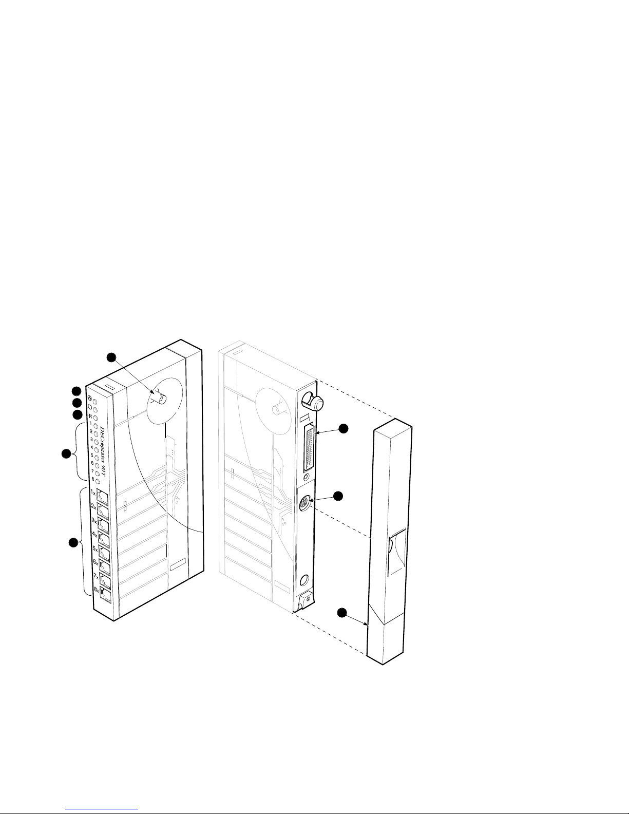
LEDs and Connectors
The front panels on the DECrepeater 90T and DECrepeater 90T+ repeaters,
although somewhat different in appearance, both contain the same indicator
lights (LEDs) and connectors. These LEDs and connectors are shown in
Figure 1–2 and Figure 1–3 and are described in Table 1–1.
Figure 1–2 DECrepeater 90T LEDs and Connectors
6
1
2
3
7
7
4
8
8
5
PJ-D120
REDUCE .45
ORG
9
9
LJ-00543-TI0A
Overview 1–3
Page 12
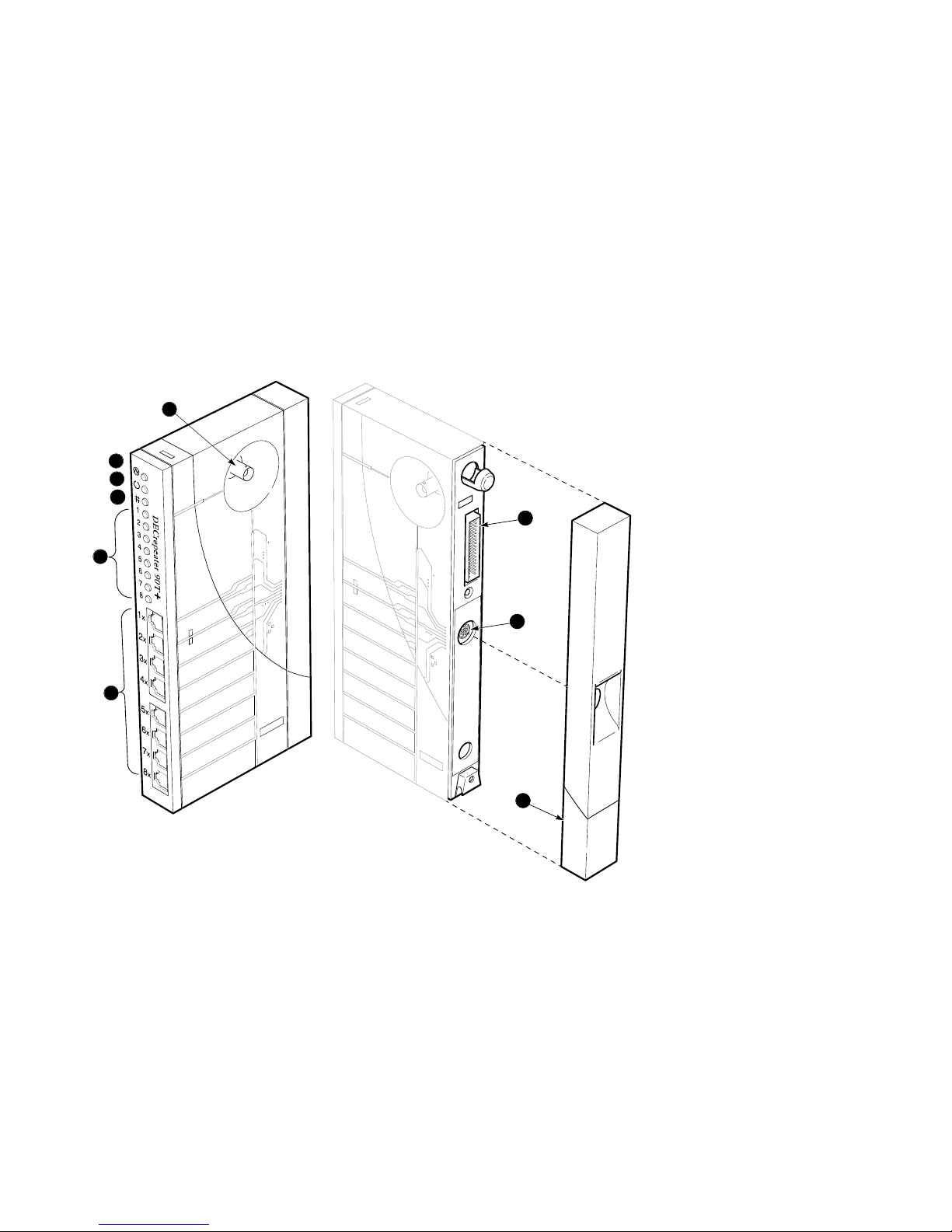
Figure 1–3 DECrepeater 90T+ LEDs and Connectors
6
1
2
3
4
5
PJ-D120
REDUCE .45
ORG
7
7
8
8
9
9
1–4 Overview
LJ-02660-TI0
Page 13
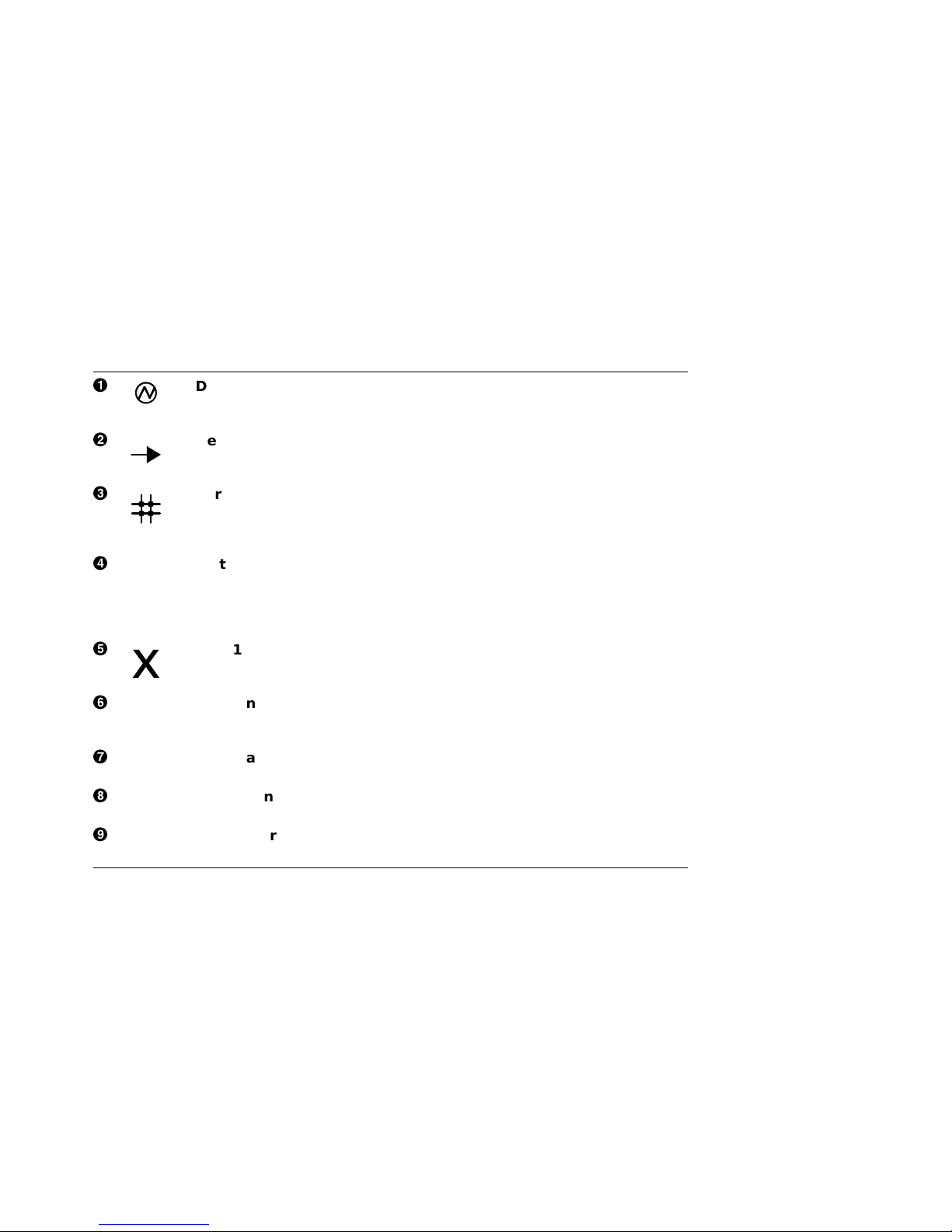
Table 1–1 DECrepeater 90T and DECrepeater 90T+ LEDs and Connectors
!
"
#
$
%
&
'
(
)
DC OK monitors the voltage.
On: The +5.0 Vdc voltage is normal.
Off: The voltage is abnormal (as when a power failure occurs).
Network activity indicator monitors the network activity.
On: There is network activity.
Off: There is no network activity.
Port 0 status indicator monitors the status of port 0.
On: Port 0 is functional.
Off: Port 0 is not functioning or has been partitioned.
Flashing: Port 0 has been partitioned by management.
Status indicators monitor the status activity of ports 1 to 8. The top
status LED represents port 1; the bottom LED represents port 8.
On: The port is functional.
Off: The port is not functioning or has been partitioned by management.
Flashing: The port has been partitioned by management.
Port 1X through 8X connectors (MJ) connect workstations and PCs to
the repeater. These connectors have internal crossovers (indicated by the
X).
Port 0 network connector (BNC) connects the repeater to the work
group ThinWire segment. Not used when the repeater is installed in the
DEChub 90 backplane.
Backplane connector provides network and power connections to the
repeater when it is installed in the DEChub 90 backplane.
Power connector receives +5.0 V from the repeater power supply. Not
used when the repeater is installed in the DEChub 90 backplane.
Back cover covers the backplane connector and mounting assembly. (Use
with standalone units only.)
Overview 1–5
Page 14

2
Configuring the DECrepeater 90T and
DECrepeater 90T+ Repeaters
Introduction
This chapter contains some of the basic configuration rules and guidelines
that must be followed to correctly install the typical DECrepeater 90T and
DECrepeater 90T+ configurations. For more detailed information about
installing IEEE 802.3 compliant multisegment LANs, refer to Section 13 of
the IEEE 802.3i-1990 standard.
Configuration Rules
The two basic constraints in IEEE 802.3 LAN configurations are segment lengths
and the number of repeaters between data terminal equipment (DTE). To ensure
the proper operation of the IEEE 802.3 physical layer and access methodology,
the network size must meet the round trip propagation delay budget.
Segment Length Constraints
Table 2–1 specifies the maximum segment lengths for ThinWire and twisted-pair
cables.
Table 2–1 Segment Lengths
Media Type Maximum Segment Length (Meters)
Mixing (coaxial) 10Base2 (ThinWire) 185
Link 10BaseT (twisted-pair) 100
Configuring the DECrepeater 90T and DECrepeater 90T+ Repeaters 2–1
Page 15

Network Constraints
The overall network constraints are imposed by the following IEEE 802.3 rules:
1. The transmission path between any two DTEs may consist of up to five
segments and four repeater sets.
When a network consists of five segments and four repeater sets, a maximum
of three of these segments may be mixing (coaxial) segments.
2. The total of all segments (up to five) shall not exceed 2500 meters.
The actual maximum segment length depends on the cable characteristics.
Longer or shorter lengths are possible depending on the performance of the
twisted-pair cable. A ThinWire segment may have a total of 30 transceivers.
Port 0 has an integral transceiver.
2–2 Configuring the DECrepeater 90T and DECrepeater 90T+ Repeaters
Page 16

3
Installation
Introduction
Before you install the DECrepeater 90T and DECrepeater 90T+ repeaters,
you should read this entire manual to become familiar with the features and
configuration rules of the repeaters. If problems occur during installation, refer
to Chapter 5, Troubleshooting. For additional information that may be useful
during installation, refer to Appendix A, Specifications and Parts List.
The repeaters may be installed on top of a desk or table, mounted on a wall by
the back cover, or installed in a DEChub 90 backplane. The only tool required for
installation is a screwdriver. The screwdriver is used to remove the back cover,
which covers the backplane connector and mounting assembly, and to mount the
repeater or the power supply on the wall.
Site Considerations
The repeaters and their power supplies can be placed in various locations,
including office areas, computer rooms, or wiring closets, as long as the
environmental requirements are met. These requirements are provided in
Table A–2, Operating Environment, in Appendix A.
Standalone Installation
To install a DECrepeater 90T or DECrepeater 90T+ repeater on top of a desk or
table, make sure that the air circulation around the repeater does not become
obstructed by papers or other materials. Refer to the environmental specifications
provided in Table A–2 in Appendix A.
Installation 3–1
Page 17
Mount the DECrepeater 90T and DECrepeater 90T+ on a Wall
To install the DECrepeater 90T or DECrepeater 90T+ as a standalone wall-mount
unit, use the following procedure:
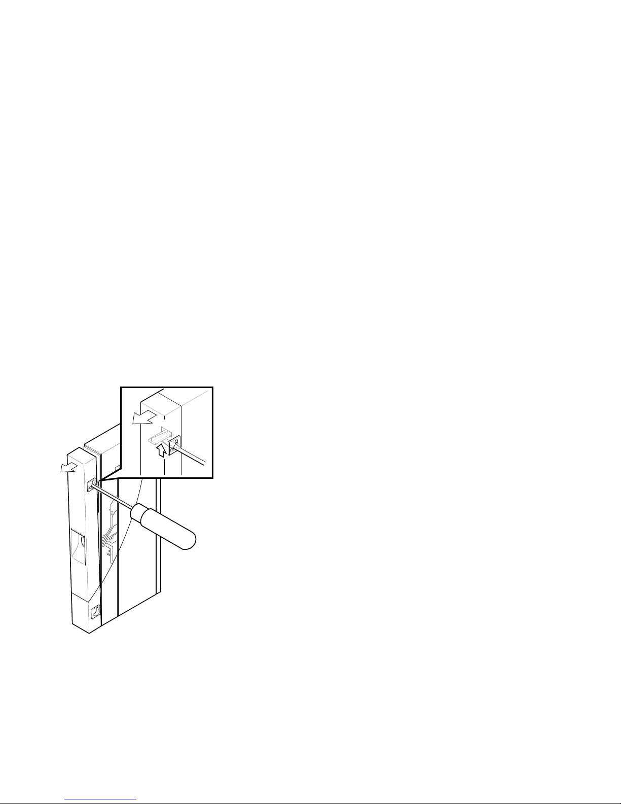
1. Remove the cover (if necessary).
a. Insert a small screwdriver into the top mounting hole on the cover
(Figure 3–1).
b. Lift the internal latch with the screwdriver, then pull the cover away and
down from the top of the unit.
Figure 3–1 Removing the Back Cover
LJ-00320-TI0
2. Use the mounting holes on the back cover to determine the placement for the
mounting screws on the wall (Figure 3–2).
3. Secure the back cover to the wall using the mounting screws.
3–2 Installation
Page 18
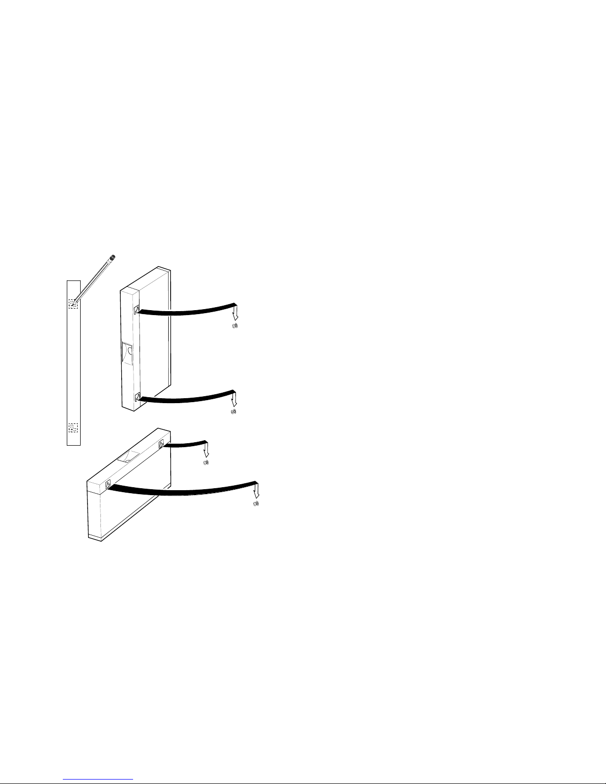
Figure 3–2 Mounting Screws
The screws should be tight enough to provide resistance if you try to remove the
back cover from the wall. However, do not make them so tight that the cover is
distorted or cannot be removed from the wall.
LJ-00701-TI0
Installation 3–3
Page 19

4. Remove the back cover from the wall.
5. Attach the back cover to the repeater.
6. Mount the repeater onto the mounting screws.
Standalone Installation Connections
To make the standalone installation connections, use the following procedure and
refer to Figure 3–3:
1. Connect the cable from the power supply to the 7-pin power connector on the
repeater. Align the power symbol on the direct current (dc) power connector
with the power symbol on the repeater and push the connector straight in.
2. Connect the repeater to the power source.
For a 240-volt power outlet, connect the power supply cord to the modular
power supply, then to the wall outlet.
For a 120-volt power outlet, connect the power supply directly to the wall
outlet.
All the LEDs should turn on during initial power-up. After approximately
.05 seconds, the network activity LED should turn off while the other LEDs
remain on.
3. Connect the Ethernet ThinWire segment to a T-connector; connect the
T-connector to the port 0 BNC network connector. Terminate the T-connector
using a 50-ohm terminator or extend the Ethernet segment to the next device.
The port 0 status activity LED should be on or flashing to indicate the
amount of traffic on the network. The LED intensity varies with the amount
of traffic: the more traffic, the brighter the LED appears.
4. Connect the twisted-pair cables to ports 1 to 8.
The crossover twisted-pair cable function is built into the repeater. Use
point-to-point wiring (with 8-pin MJ connectors) when connecting a device to
the twisted-pair ports.
The port LED should turn on when a port is correctly terminated and first
receives network activity. Verify the operation of each port by sending
information to the device being tested.
The repeater is now installed.
3–4 Installation
Page 20

Figure 3–3 Standalone Installation
T-Connector
50-Ohm
Terminator
PC
or
Workstation
LJ-00703-TI0A
Installation 3–5
Page 21

Backplane Installation
To install a DECrepeater 90T or DECrepeater 90T+ in a DEChub 90 backplane,
use the following procedure:
1. Remove the back cover (if necessary).
a. Insert a small screwdriver into the top mounting hole located on the
cover.
b. Lift the internal latch with the screwdriver and pull the cover away and
down from the top of the unit (Figure 3–1).
2. Place the lower mounting tab, located on the back of the repeater, into the
correct mounting slot on the backplane (Figure 3–4).
3. Rock the repeater into place. You will hear a click when the repeater is
secured in the slot.
4. Supply power to the backplane if this is a new installation.
The port 0 status activity LED should be on or flashing to indicate the
amount of traffic on the network. The LED intensity varies with the amount
of traffic: the more traffic, the brighter the LED appears.
The port status LEDs for unconnected ports should turn off when network
traffic is established.
The repeater is now installed.
The repeaters can be installed into or removed from the DEChub 90
backplane while power is supplied to the backplane. (This is referred to
as a hot swap.)
3–6 Installation
Note
Page 22

Figure 3–4 Installing a DECrepeater 90T Repeater into the DEChub 90
Backplane
LJ-00704-TI0
Installation 3–7
Page 23

Shielded Twisted-Pair Environments
The DECrepeater 90T+ accommodates environments where shielded twisted-pair
10BaseT installations are required. The DECrepeater 90T+ has shielded MJ
connectors, but retain the 100-ohm impedance environment. For installations
that require 160-ohm line impedances, connections to the repeater should be
made through a 10BaseT balun.
The DECrepeater 90T+ shields are electrically common to earth ground
connections in both standalone and backplane installations. The shielded
connections at the user end of twisted-pair links should be impedance-coupled to
earth ground to avoid direct current (dc) or low-frequency ground loop currents.
3–8 Installation
Page 24

4
Managing the DECrepeater 90T and
DECrepeater 90T+
Introduction
This chapter provides information about managing the DECrepeater 90T and
DECrepeater 90T+ repeaters on a network using the Maintenance Operations
Protocol (MOP) for VMS or ULTRIX operating systems. This chapter also
describes the management functions, commands, techniques, and messages.
The repeaters are managed online using a DECbridge 90 series unit in a
DEChub 90 backplane. All commands that affect the repeaters are part of the
DECbridge 90 series command set.
Functions
Online management allows the user to perform the following functions:
• Identify all repeaters in the DEChub 90.
• Examine port status (enabled, disabled, properly operating, or inoperative) of
repeater ports that share the DEChub 90 backplane with a bridge.
• Examine the work group address database entries 1 to 200, annotated with
the repeater port to which each is attached, if any.
• Reset any repeater in the DEChub 90 backplane.
• Enable or disable a repeater port.
• Define the bridge password.
See the Description of Commands section of this chapter for more information
about command syntax.
Managing the DECrepeater 90T and DECrepeater 90T+ 4–1
Page 25

Components Needed
You need the following components to manage a repeater online:
• DEChub 90 backplane
• DECbridge 90 work group bridge
• DECrepeater 90T or DECrepeater 90T+
Accessing MOP from VMS Systems
The MOP console carrier on a VMS operating system is included as part of
the Network Control Program (NCP) facility, which requires a DECnet license.
You do not need increased user privileges to use the NCP facility; however, to
establish a console carrier session, you must know the following:
• The Ethernet address of the bridge used for management
• The Ethernet name of the circuit containing the bridge
The circuit name is needed because a VMS operating system may have more than
one Ethernet interface. The Ethernet address is located on the front panel label
on a DECbridge 90 series unit.
Table 4–1 lists the Ethernet circuit names that apply. The Ethernet circuit names
are based on system type.
Table 4–1 Ethernet Circuit Names for Systems
System Ethernet Circuit Name
VAX 6000 and VAX 9000 XMI computers mna-0
BI based systems (VAX 6300 and VAX 6400 computers) bna-0
VAX 4000 computer series isa-0
MicroVAX systems and VAX 3600 and VAX 3900
computers
VAXstation 2000 and VAXstation 3000 computer series sva-0
VAX–11/780 and VAX–11/785 computers (UNIBUS) una-0
4–2 Managing the DECrepeater 90T and DECrepeater 90T+
qna-0
Page 26

Example:
If the bridge address is 08-00-2B-01-23-45 and the Ethernet circuit name is
sva-0, a typical VMS system command line to establish the session from a
VAXstation 3100 computer is:
$ MCR NCP CONNECT VIA SVA-0 PHYSICAL ADDRESS 08-00-2B-01-23-45
Return
When you establish the connection, the following message appears on the screen:
Console connected (press CTRL/D when finished)
Accessing a Bridge Repeatedly
If you need to access a specific bridge repeatedly, you can enter the bridge
Ethernet address in the NCP database by choosing an arbitrary address in area
13. Bridge names in the NCP database may have a maximum of six characters.
Example:
If you name your bridge DBRG1 on address 13.87 and access it from a VAX 6400
computer (the Ethernet circuit name is bna-0), you could use the following
commands:
$ NCP
NCP> DEFINE NODE DBRG1 ADDRESS 13.87 HARDWARE 08-00-2B-01-23-45 SERVICE CIR BNA-0
NCP> SET NODE DBRG1 ALL
Return
To access the bridge, enter the following:
$ NCP CONNECT NODE DBRG1
Return
$ NCP
NCP> DEFINE NODE DBRG1 ADDRESS 13.87 HARDWARE 08-00-2B-01-23-45 SERVICE CIR BNA-0
NCP> SET NODE DBRG1 ALL
Return
To access the bridge, enter the following:
Return
Return
$ NCP CONNECT NODE DBRG1
Return
Accessing MOP from ULTRIX Systems
On ULTRIX operating systems, the console carrier is a separate utility included
as part of the MOP option. This option is part of the regular distribution;
however, it is not selected by default and is not included in the basic installation.
You can install the MOP option from the original distribution media using the
setld utility. You must have superuser privileges to invoke console carrier.
After the MOP option is installed, each bridge to be managed must be given a
name and a dummy node number using the addnode utility. For example:
# addnode 13.1 DBRG1
Return
Managing the DECrepeater 90T and DECrepeater 90T+ 4–3
Page 27

After the name and node number are assigned, you can establish the link at any
time using the ccr command:
# ccr -n DBRG1 -h 08-00-2b-01-23-45 -c sva-0
In this example, the -h qualifier is followed by the station address of the
DECbridge unit to be attached. The -c qualifier is followed by the name of the
Ethernet circuit to use for the connection. Ethernet circuit names, based on
system type, apply. Refer to Table 4–1 for circuit names.
Return
Console Carrier User Interface
The DECbridge 90 is not shipped with a pre-set password; therefore, no password
prompt appears on the screen when you connect for the first time. For secure
operation of the DECbridge 90, you should define a password using the DEFINE
BRIDGE PASSWORD command.
The password prompt is represented by the pound sign (#). If you do not define a
password, then the password prompt does not appear on the screen when you log
in.
You have three attempts to enter a password; if all three attempts fail, then you
must disconnect and try again.
After you enter the correct password, or if there is no password, the DECbridge
console carrier management banner and prompt appears on the screen as follows:
Copyright © Digital Equipment Corporation 1991.
DEWGB V2.0 08-00-2B-2D-9B-81
EPROM V2.7 ©1991,92 Digital Equip Corp 25-JUN-92
DECbridge>
Console Carrier Command Language
You can type a question mark (?) at any point in the command line to display
a list of the options available at that point in the command line. The system
accepts unique command abbreviations.
Table 4–2 summarizes DECbridge commands that apply to the repeaters. For
a complete list of commands, refer to the DECbridge 90 Owner’s Manual or the
DECbridge 90FL Owner’s Manual.
4–4 Managing the DECrepeater 90T and DECrepeater 90T+
Page 28

Table 4–2 Summary of DECrepeater 90T and DECrepeater 90T+ Commands
Command Argument and Parameter
DEFINE
LIST BRIDGE
SET
SHOW ADDRESS [start index,[stop index]
1
BRIDGE AGE age
BRIDGE FLOOD
ENABLE
DISABLE
BRIDGE HUB MANAGEMENT
ENABLE
DISABLE
BRIDGE PASSWORD password string
BRIDGE SPANNING TREE
ENABLE
DISABLE
PORT port number
ENABLE
DISABLE
PROTOCOL protocol number
FILTER ALL protocol identifier
FILTER BACKGROUND protocol identifier
FILTER GROUP protocol identifier
FILTER WORKGROUP protocol identifier
FORWARD protocol identifier
NONE
REPEATER
PROTOCOL protocol number
2
BRIDGE HUB MANAGEMENT
ENABLE
DISABLE
PORT [hub number,]slot number,port number
ENABLE
DISABLE
REPEATER [[hub number,]slot number]RESET
1
Changes made with the DEFINE command change only the default settings, which are assumed on
power-up or reset. DEFINE commands do not change the currently active values.
2
The SET commands change only the currently active values, but do not affect the defaults that are
assumed on power-up or reset.
Managing the DECrepeater 90T and DECrepeater 90T+ 4–5
(continued on next page)
Page 29

Table 4–2 (Cont.) Summary of DECrepeater 90T and DECrepeater 90T+
Commands
Command Argument and Parameter
PORT [hub number,]slot number,port number
REPEATER [[hub number,]slot number]
Description of Command Parameters
A start index or stop index for an address is a decimal index into the work group
forwarding database in the range of 1 to 200.
A slot number is a single number ranging from 1 to 8 that identifies a hub slot
containing a repeater. When two DEChub backplanes are connected together, the
hub number (1 or 2) is specified before the slot number. For example, the hub slot
number 2,4 refers to the fourth slot from the left in the second DEChub, which is
the hub that does not contain the DECbridge 90.
A password string is a string with a maximum of 16 characters.
A port number is either a DECbridge 90 port, or the number of a port on a
repeater that is installed in the DEChub backplane with the bridge. The bridge
backbone port is 1. The work group port is 2. A repeater port is identified by a
hub slot number and the port number within the slot.
4–6 Managing the DECrepeater 90T and DECrepeater 90T+
Page 30

Description of Commands
This section describes the commands used with the DECrepeater 90T and
DECrepeater 90T+ repeaters. The examples used to explain the commands are
based on the configuration shown in Figure 4–1.
Figure 4–1 Sample Configuration
DECserver 90L
08-00-2B-0F-19-23
DECrepeater 90T
DECrepeater 90C
VT420
Disk Server
08-00-2B-A6-43-17
DECrepeater 90C
DECrepeater 90T
DECbridge 90
08-00-2B-1D-07-21
3
1
2
1
2
5 6
4
3
5 6
4
8
7
Power
Supply
MMJ
Cable
8
7
Power
Supply
H4005
ThinWire
Cable
AUI
Cable
PC PC
08-00-2B-10-6A-31
08-00-2B-16-23-4C
Managing the DECrepeater 90T and DECrepeater 90T+ 4–7
08-00-2B-10-20-30
LJ-00947-TI0A
Page 31

DEFINE BRIDGE HUB_MANAGEMENT DISABLE
SET BRIDGE HUB_MANAGEMENT DISABLE
Disables all repeater management through the DECbridge 90 unit for repeater
units in the DEChub 90 backplane. When disabled, you receive an error message
with the SHOW REPEATER, SET PORT, or SHOW PORT commands on repeater
ports. You do not receive port number information from the SHOW ADDRESS
command.
DEFINE BRIDGE HUB_MANAGEMENT ENABLE
SET BRIDGE HUB_MANAGEMENT ENABLE
Reverses the affect of the SET or DEFINE BRIDGE HUB_MANAGEMENT
DISABLE commands.
DEFINE BRIDGE PASSWORD password string
Lets you change the password string. You are prompted twice for a new password.
The password may be a maximum of 16 characters and does not appear on the
screen. The system saves the new password. There is no corresponding SET
command because the DEFINE BRIDGE PASSWORD takes effect immediately.
The MOP option provides a mechanism for setting and checking passwords.
This mechanism is intended to provide protection against accidental tampering
with parameters and is not intended as a security feature. No attempt is made
to prevent compromise of the password by malicious users. The DECbridge 90
should not be used in applications that absolutely depend on the prevention of
any unauthorized modifications to the parameters.
LIST BRIDGE
Displays the nonvolatile bridge-wide parameters.
4–8 Managing the DECrepeater 90T and DECrepeater 90T+
Page 32

SET PORT [hub number,] slot number,port number DISABLE
Disables the attachment of a specific repeater port in the DEChub backplane.
The port status indicator on the selected repeater flashes, indicating that the
port was disconnected by the network manager. There is no equivalent DEFINE
command for disabling repeater ports.
Example 1:
The expected response to a SET PORT DISABLE command for a repeater appears
as follows:
DECbridge>SET PORT 1,3,2 DISABLE
Return
Hub 1 slot 3 port 2 segment counter 0 status: disabled
SET PORT [hub number,] slot number, port number ENABLE
Reverses the effect of SET PORT DISABLE for DECrepeater 90 ports.
Example 2:
The expected response to a SET PORT ENABLE command for a repeater appears
as follows:
DECbridge>SET PORT 1,3,2 ENABLE
Hub 1 slot 3 port 2 segment counter 0 status: no carrier loopback
Return
SET REPEATER [hub number,]slot number RESET
Resets a specific repeater. There is no output response to this command. All
disabled ports are enabled.
SHOW ADDRESS [start index,[stop index]]
Displays the station address in a selected range (1 to 200) of entries in the
address database. The start index value always appears; however, other entries
in the range appear only if they are not empty. Addresses in this database are
all in the work group. If indexes are omitted, the addresses of all stations in the
work group are listed.
Managing the DECrepeater 90T and DECrepeater 90T+ 4–9
Page 33

When the DECbridge 90 unit is used with a DECrepeater 90T or
DECrepeater 90T+ repeater, the hub slot number and repeater port to which each
station is attached will also appear on the screen. Note that it may take several
minutes for the SHOW ADDRESS command to accurately reflect the correct
repeater port number for stations recently added to the network or stations
that have been moved from one port to another. See Appendix B, Management
Details, for more information about the SHOW ADDRESS command.
Example 1:
The SHOW ADDRESS command displays all addresses contained within the
hub configuration. Address 5 and address 7 show the same hub, slot, and port
because both devices are daisy chained on the same port.
DECbridge>SHOW ADDRESS
Return
Address 1: 08-00-2B-0F-19-23
Address 2: 08-00-2B-10-20-30 hub 2 slot 8 port 4
Address 5: 08-00-2B-10-6A-31 hub 2 slot 3 port 3
Address 6: 08-00-2B-A6-43-17 hub 1 slot 3 port 5
Address 7: 08-00-2B-16-23-4C hub 2 slot 3 port 3
Example 2:
The expected response to a SHOW ADDRESS command to a nonexisting address
appears as follows:
DECbridge>SHOW ADDRESS 3
Return
Address 3: unused
Example 3:
The expected response of a SHOW ADDRESS command to a valid address
appears as follows:
DECbridge>SHOW ADDRESS 2
Return
Address 2: 08-00-2B-10-20-30 hub 2 slot 8 port 4
Example 4:
The expected response of a SHOW ADDRESS command for a range of addresses
appears as follows:
DECbridge>SHOW ADDRESS 2,6
Return
Address 2: 08-00-2B-10-20-30 hub 2 slot 8 port 4
Address 5: 08-00-2B-10-6A-31 hub 2 slot 3 port 3
Address 6: 08-00-2B-A6-43-17 hub 1 slot 3 port 5
4–10 Managing the DECrepeater 90T and DECrepeater 90T+
Page 34

SHOW PORT [hub number,] slot number, port number
Shows whether the port is enabled or disabled and shows the operational status
of the port. Hub numbers can be 1 or 2; slot numbers can be 1 to 8. For the
DECrepeater 90T and DECrepeater 90T+, port numbers are 1 to 8; for the
DECrepeater 90C, port numbers are 1 to 6.
Example 1:
The expected response to a SHOW PORT command appears as follows:
DECbridge>SHOW PORT 3,2
Hub 1 slot 3 port 2 segment counter 0 status: disabled-no carrier
loopback
Return
The hub was not defined in the command so the default (1) was used.
Example 2:
A SHOW PORT command for hub 2 appears as follows:
DECbridge>SHOW PORT 2,3,2
Return
Hub 2 slot 3 port 2 segment counter 0 status: operational
SHOW REPEATER [[hub slot number,]slot number]
Shows the type of repeater and the port status for each port on that repeater.
The hub number can be 1 or 2, and slot numbers can be 1 to 8. If you do not
include parameters, information is shown for all repeaters in both hubs.
Example 1:
The expected response to a SHOW REPEATER command appears as follows:
DECbridge>SHOW REPEATER
Return
Hub 1 slot 3 twisted pair, repeater, rev.1, 8 ports.
Hub 1 slot 4 ThinWire repeater, rev.1, 6 ports.
Hub 2 slot 3 ThinWire repeater, rev.1, 6 ports.
Hub 2 slot 6 twisted pair repeater, rev.1, 8 ports.
Hub 2 slot 8 twisted pair repeater, rev.1, 8 ports.
Note that the DECrepeater 90T or DECrepeater 90T+, and the DECrepeater 90C
repeaters are installed in the hub.
Example 2:
The response to a SHOW REPEATER command to a slot that contains a device
other than a repeater appears as follows:
DECbridge>SHOW REPEATER 1
Return
No repeater responds.
Managing the DECrepeater 90T and DECrepeater 90T+ 4–11
Page 35

Example 3:
The response to a SHOW REPEATER command to an empty slot appears as
follows:
DECbridge>SHOW REPEATER 7
Return
No repeater responds.
Example 4:
The response to a SHOW REPEATER command for a particular repeater appears
as follows:
DECbridge>SHOW REPEATER 3
Hub 1 slot 3 twisted pair, rev.1, 8 ports.
Hub 1 slot 3 port 0 segment counter 0 status: operational
Hub 1 slot 3 port 1 segment counter 1 status: no carrier loopback
Hub 1 slot 3 port 2 segment counter 0 status: disabled
Hub 1 slot 3 port 3 segment counter 0 status: operational
Hub 1 slot 3 port 4 segment counter 1 status: no carrier loopback
Hub 1 slot 3 port 5 segment counter 1 status: no carrier loopback
Hub 1 slot 3 port 6 segment counter 1 status: no carrier loopback
Hub 1 slot 3 port 7 segment counter 1 status: no carrier loopback
Hub 1 slot 3 port 8 segment counter 1 status: no carrier loopback
Return
Example 5:
The response to a SHOW REPEATER command for hub 2 slot 3 appears as
follows:
DECbridge>SHOW REPEATER 2,3
Hub 2 slot 3 ThinWire, rev.1, 6 ports.
Hub 2 slot 3 port 0 segment counter 0 status: operational
Hub 2 slot 3 port 1 segment counter 1 status: no carrier loopback
Hub 2 slot 3 port 2 segment counter 1 status: no carrier loopback
Hub 2 slot 3 port 3 segment counter 1 status: no carrier loopback
Hub 2 slot 3 port 4 segment counter 1 status: no carrier loopback
Hub 2 slot 3 port 5 segment counter 0 status: operational
Hub 2 slot 3 port 6 segment counter 1 status: no carrier loopback
Return
Example 6:
The response to a SHOW REPEATER command when the DECbridge 90 is not
the hub manager or when the DECbridge 90 is still in the power-up stage appears
as follows:
DECbridge>SHOW REPEATER
The DECbridge 90 is not the designated hub manager.
There is a 60-second delay after power-up before the DECbridge 90 takes control
of the hub.
4–12 Managing the DECrepeater 90T and DECrepeater 90T+
Return
Page 36

Typical Management Techniques
The DECrepeater 90T and DECrepeater 90T+ can be managed in the following
ways:
• As standalone units using LEDs
The repeaters come with LEDs that indicate system status in a standalone
configuration.
• Online within a group of repeaters installed in a DEChub 90
In a DEChub 90 environment, the repeaters may be managed using both
LEDs and online management.
Remote Network Management with the DECbridge 90
You can manage the repeaters with a DECbridge 90 work group bridge and
a DEChub 90 backplane. The DECbridge 90 unit communicates across the
DEChub 90 backplane with any repeaters in the DEChub. You can also
connect two DEChub 90 backplanes together and manage the repeaters in
both DEChub 90 backplanes using one DECbridge 90 unit.
The DECbridge 90 unit communicates with the repeater units using unique
signals on the DEChub 90 backplane. The two DEChub 90 backplanes are
connected with two cables:
1. ThinWire coaxial cable to carry the work group Ethernet signals
2. DECconnect office cable to carry the management signals
If two DEChub 90 backplanes are being managed by one bridge, the
backplanes must be connected BNC to BNC using ThinWire cable
(order number BC16M-xx) and a DECconnect office cable (order number
BC16E-xx). (The xx in the order number represents the length.)
Management Disconnect
A port can be partitioned at any time by the management protocol. The
management protocol can be used only for the repeater ports mounted in
the DEChub 90 backplane and connected to a DECbridge 90. When a port is
disconnected by the management protocol, it can be reconnected either by turning
the power off and then on again, or by using the management protocol. If the
port LED flashes approximately twice a second, the port is partitioned by the
management protocol.
Managing the DECrepeater 90T and DECrepeater 90T+ 4–13
Note
Page 37

Whether your configuration is a standalone or a DEChub 90 installation, you
should create a network topology map to help facilitate management tasks.
Figure 4–2 shows an example of a typical network topology map.
Figure 4–2 Typical Network Topology Map
DEChub 90
DECrepeater 90T DECbridge 90
Slot 1 DECrepeater 90C
Port 1
Node - Address - Username
Node - Address - Username
Port 2
Port 3
Node - Address - Username
Node - Address - Username
Port 4
Port 5
Node - Address - Username
Node - Address - Username
Port 6
Port 7
Node - Address - Username
Node - Address - Username
Port 8
Slot 2
Port 1
Node - Address - Username
Node - Address - Username
Port 2
Port 3
Node - Address - Username
Node - Address - Username
Port 4
Port 5
Node - Address - Username
Node - Address - Username
Port 6
Port 7
Node - Address - Username
Node - Address - Username
Port 8
Slot 8
Port 1
Port 2
Port 3
Port 4
Port 5
Port 6
Port 7
Port 8
Address
Address
Address
Address
Address
Address
Address
Address
LJ-00956-TI0A
Management Session
To perform online management commands, establish a MOP console carrier
session with the bridge from any remote node. After you connect to the bridge,
the following prompt appears on the screen:
DECbridge>
When a bridge goes through a power cycle or is reset, the bridge begins to poll
repeaters for status. This process includes a special algorithm to determine
which repeater ports have stations that are attached. The time to complete this
algorithm depends on the number of repeaters and the network activity. You
should allow time before proceeding to manage the hub. For the same reason, it
can take time for the system to report on stations or repeaters that are moved in
the hub. See Appendix B, Management Details, for more information.
Example of a Typical Management Session
The following steps show how you can use the SHOW REPEATER and SHOW
ADDRESS commands in a typical management session.
1. Determine what repeaters are in the hub.
DECbridge>SHOW REPEATER
Return
Hub 1 slot 5 ThinWire repeater, rev.0, 6 ports.
In this example, there is a ThinWire repeater (DECrepeater 90C) in the same
hub (hub 1) as the bridge (if this is a 2-hub configuration). The repeater is in
slot 5 with six ThinWire ports.
4–14 Managing the DECrepeater 90T and DECrepeater 90T+
Page 38

2. Determine what stations are connected to the repeaters in the hub.
DECbridge>SHOW ADDRESS
Return
Address 1: 08-00-2B-19-94-FB
Address 2: 08-00-2B-1E-2D-0C hub 1 slot 5 port 3
This indicates that a station with address 08-00-2B-1E-2D-0C is connected to
the repeater in slot 5 on port 3. At this point, without physical examination,
you have enough information to construct a network map.
3. Determine the status of all ports on the repeater.
DECbridge>SHOW REPEATER 5
Return
Hub 1 slot 5 twisted pair, rev.1, 6 ports.
Hub 1 slot 5 port 0 segment counter 0 status: operational
Hub 1 slot 5 port 1 segment counter 0 status: excessive collisions
Hub 1 slot 5 port 2 segment counter 0 status: excessive length collision
Hub 1 slot 5 port 3 segment counter 0 status: operational
Hub 1 slot 5 port 4 segment counter 0 status: excessive length collision
Hub 1 slot 5 port 5 segment counter 0 status: excessive length collision
Hub 1 slot 5 port 6 segment counter 0 status: excessive length collision
Hub 1 slot 5 port 7 segment counter 0 status: excessive length collision
Hub 1 slot 5 port 8 segment counter 0 status: excessive length collision
Continue to use the SHOW REPEATER command for each port on the
repeater.
If Problems are Reported
Table 4–3 describes the status messages and the most common causes.
Table 4–3 Status Messages and Causes
Message Most Common Cause
Operational Cable connected, everything OK.
Excessive length collision Cable fault, usually either a port that is not connected
Excessive collisions Cable fault, usually either a port that is not connected
No carrier loopback Cable fault, usually a shorted cable.
Transmit carrier drop out Cable fault, usually a shorted cable.
Managing the DECrepeater 90T and DECrepeater 90T+ 4–15
to anything or an open cable. In the case of 10BaseT,
the remote station may be powered down (no link
beat).
to anything or an open cable. In the case of 10BaseT,
the remote station may be powered down (no link
beat).
(continued on next page)
Page 39

Table 4–3 (Cont.) Status Messages and Causes
Message Most Common Cause
Jabber Stations connected to this port continue to transmit;
expect a faulty station.
The operational condition is normal. All other conditions cause the repeater
to automatically partition the port. When the condition clears, the repeater
automatically reconnects the port and reports it as operational unless it is
partitioned by management.
To help solve intermittent problems, the repeater reports a segmentation count.
This count runs from 0 to 15 and then latches at 15. Every time you enter the
SHOW REPEATER command, this count is set to zero.
If this count is not zero, you can tell that a port has partitioned since the last
SHOW REPEATER command. This partitioning occurs normally if users turn
stations on and off, or if cables are connected and disconnected from the repeater
during installation and reconfiguration. If none of these normal causes have
occurred, there may be an intermittent problem with cabling or attached stations.
To Disable a Port
The following command allows the hub manager to disable a particular port on a
repeater. This may be useful if stations attached to that port are causing network
difficulties.
DECbridge>SET PORT 5,1 DISABLE
Return
Hub 1 slot 5 port 1 segment counter 0 status: disabled-no carrier
loopback
To Reset the Repeater
The following command resets the repeater to power-up condition. This includes
restoring any ports that have been partitioned by the hub manager as well as
resetting the segmentation counters.
DECbridge>SET REPEATER 5 RESET
4–16 Managing the DECrepeater 90T and DECrepeater 90T+
Return
Page 40

Error Messages
Table 4–4 describes the DECbridge 90 messages. For a complete list of messages,
refer to either the DECbridge 90 Owner’s Manual or the DECbridge 90FL
Owner’s Manual.
Table 4–4 DECbridge 90 Messages
Error Message Description
Address n: unused Address number n does not contain a station address.
Confirmation error -
password not changed
DECbridge 90 is not the
designated hub manager
The second entry or verification of the new password of
the DEFINE BRIDGE PASSWORD command did not
match the first entry.
The DECbridge 90 was not the designated hub manager
when either the SHOW PORT or SHOW REPEATER
command was issued. This occurs when
• The bridge is reset and, for 60 seconds, the
DECbridge is not the hub manager.
• Another DECbridge unit is acting as the current hub
manager.
• A fault exists in the BC16E cable or in the
connections between two DEChub backplanes.
• A fault exists in the power supply of one of the
DEChub backplanes. This prevents repeater
management communication.
Hub management disabled A SHOW PORT or SHOW REPEATER command was
Hub number and slot number
[[hub], slot]. Hub is 1 or 2,
slot is 1-15
Hub h slot s - port number
out of range
issued to a DECbridge 90 for which repeater management
is disabled. Enable repeater management with the SET
BRIDGE HUB_MANAGEMENT ENABLE command
before trying again.
One or more parameters of the SHOW REPEATER
command were out of range. The hub number must
be either 1 or 2. The slot number must be between 1 and
15.
The port number of the SHOW PORT command was out
of range for the device in hub h slot s. Use the SHOW
REPEATER command to determine the number of ports
for the device and to specify a port number within that
range.
Managing the DECrepeater 90T and DECrepeater 90T+ 4–17
(continued on next page)
Page 41

Table 4–4 (Cont.) DECbridge 90 Messages
Error Message Description
Hub h slot s not a repeater The device does not use the same management protocol as
Hub h slot s unrecognized
type
No repeater responds There is no repeater installed in the requested hub slots,
No such port The bridge port number of the SHOW PORT command
Password too long - not
changed
Port number [[hub,]slot,]port One of the parameters of a SET PORT or DEFINE PORT
Station address number
[first [,last] ] in range 1-200
Unsupported by this
hardware revision
??? A command or parameter was not recognized. Press the
180501 A loopback diagnostic has run and passed on the backbone
180201 A loopback diagnostic has run and passed on the work
1805:00-00-00-00
01
1802:00-00-00-00
01
the repeaters. The device ports, if any, cannot be managed
by the DECbridge 90 unit.
The repeater type in hub h slot s is not known to the
DECbridge 90. The repeater ports can still be managed
with the DECbridge 90.
or the repeater is not functioning.
was invalid. Valid numbers are 1 and 2.
A password longer than 16 characters was given to the
DEFINE BRIDGE PASSWORD command.
command was not a valid hub, slot, or port number.
One or more parameters of the SHOW ADDRESS
command was invalid. The valid range is 1 to 200.
This occurs when you attempt to execute a SET or
DEFINE BRIDGE FLOOD command on a bridge with
a firmware revision of 1 (DECbridge 90 V1.4) but have
loaded V2.5 or a later version flash EPROM. The old
hardware revision does not support flood mode. These
version numbers appear in the MOP console connection
banner.
question mark (?) key to display valid commands.
port. If the backbone port is not receiving any messages,
this diagnostic is run every 10 minutes.
group port. If the work group port is not receiving any
messages, this diagnostic is run every 10 minutes.
A loopback diagnostic has run and failed on the backbone
port. The diagnostic is tried every 5 seconds until the test
passes.
A loopback diagnostic has run and failed on the work
group port. The diagnostic is tried every 5 seconds until
the test passes.
4–18 Managing the DECrepeater 90T and DECrepeater 90T+
Page 42

Standalone Configuration Management
The recommended process for managing a small standalone network is as follows:
1. Maintain records indicating which stations are connected to each port on each
repeater. It may be helpful to draw a network topology map (Figure 4–2).
2. Observe the LEDs on the repeater for network status. Refer to Table 1–1 for
a description of each LED and its function.
Note
After you power up a standalone repeater, all LEDs, except the network
activity LED, stay on if there are no active connections, or if there is no
hardware or network activity. After an active station is connected to one
of the ports, the LED for the active port stays on and all other ports turn
off.
Managing the DECrepeater 90T and DECrepeater 90T+ 4–19
Page 43

5
Troubleshooting
Introduction
This chapter provides troubleshooting information for the DECrepeater 90T
and DECrepeater 90T+ when used as standalone units or when installed in the
DEChub 90 backplane.
Before you start to troubleshoot a problem:
1. Verify the installation of the repeater. The installation must meet the
configuration rules provided in Chapter 2, Configuring the DECrepeater 90T
and DECrepeater 90T+ Repeaters.
2. Note the fault condition.
3. Isolate the problem.
Port Partitioning
Any messages or data packets received from any port by the repeater are
transmitted to all ports. The port status LEDs display the following port
partition status:
On The port is not partitioned.
Off The port is autopartitioned.
Flashing The port is partitioned by management.
Each port is automatically controlled by the repeater function and can be
partitioned for any of the reasons listed in Table 5–1.
Troubleshooting 5–1
Page 44

Table 5–1 DECrepeater 90T and DECrepeater 90T+ Status Indicators
LED Fault Non-Fault
Port 0 off Open cables
Ports 0 to 8
flashing
Ports 1 to 8 off Open cables
Shorted cables
Cables not properly connected
Cables not properly terminated
– Partitioned by management.
Shorted cables
Cables not properly terminated
Port not connected.
Port not connected.
DECrepeater 90T and DECrepeater 90T+ Standalone
Troubleshooting
To troubleshoot a DECrepeater 90T or DECrepeater 90T+ standalone installation,
refer to Table 5–2 for a list of possible error conditions and the corrective action.
Table 5–2 Troubleshooting a DECrepeater 90T and DECrepeater 90T+
Standalone Unit
If... Then... Do this...
All LEDs are off. Check the ac power connection. Check that the power
Check the power supply. Check the 7-pin connector
The network activity
LED is off.
There is low network activity or
no network activity.
supply is properly plugged
into the power outlet.
Check the power to the
power outlet.
at the repeater unit.
If the connections are
okay, replace either the
power supply (for 120 V
operation) or both the
power supply cord and
power supply (for 220 V
operation).
Ensure that network
activity is present.
(continued on next page)
5–2 Troubleshooting
Page 45

Table 5–2 (Cont.) Troubleshooting a DECrepeater 90T and DECrepeater 90T+
Standalone Unit
If... Then... Do this...
If the network activity LED still
fails to light
If the network activity LED
lights momentarily, the LED
portion of testing has passed.
If the network LED fails to light
The port status LED is
off.
All port LEDs are off. A connection has not been made. Remove all network
Ensure that the cable has
activity on it.
If the LED still fails to light
If any LED other than the
network activity LED turns off,
the repeater has failed this part
of the self-test.
If all LEDs except the network
activity LED are on, this portion
of the self-test has passed.
Turn the repeater off and
on by unplugging and
replugging the power
supply in. Check that
the network activity LED
comes on momentarily.
Replace the repeater.
Switch to an unused port
or replace the repeater.
connections. Turn the
repeater off and on by
unplugging and replugging
the power supply. All LED
indicators turn on. Only
the network activity LED
turns off.
Replace the repeater.
Connect a known active
ThinWire network segment
to the repeater. The status
LED for the connected
port will stay on while
all status LEDs for the
unconnected ports should
turn off as soon as the first
connection to the active
segment is made.
(continued on next page)
Troubleshooting 5–3
Page 46

Table 5–2 (Cont.) Troubleshooting a DECrepeater 90T and DECrepeater 90T+
Standalone Unit
If... Then... Do this...
If the status LED for the
connected port stays on and the
status LED for the unconnected
ports stay off, then the connected
port is okay.
If the status LED for the
unconnected ports do not turn off
while the LED for the connected
port remains on, there is a
possible problem with the cable
or that port.
If the same condition exists
when a good cable is plugged in
Continue installing other
network cables for each port
that you are going to use.
If the LED for each properly
terminated port remains off
when a cable is connected, the
repeater is defective.
Continue installing the
other network cables for
each port that you are
going to use.
Try another port. If the
same conditions exist,
check for a cable problem
by connecting a good cable
with a good device at the
other end.
Replace the repeater.
The indicator LED for each
properly terminated port
should turn on.
Replace the repeater.
5–4 Troubleshooting
Page 47

DECrepeater 90T and DECrepeater 90T+ Backplane
Troubleshooting
To troubleshoot a DECrepeater 90T or DECrepeater 90T+ installed in a
DEChub 90 configuration, refer to Table 5–3 for a list of possible error conditions
and the corrective action.
Table 5–3 Troubleshooting a DECrepeater 90T and DECrepeater 90T+ in a
DEChub 90 Backplane
If... Then... Do this...
The power LED is off. The repeater does
not have the correct
operating voltage.
If the power LED on
the DEChub 90 is off,
there is a problem with
the DEChub 90 power
supply.
If the power LED on
the DEChub 90 power
supply is on, check if
other component power
LEDs are off? If other
components LEDs are
on, the repeater has a
power problem.
If the power LED on
the DEChub 90 power
supply is on, check if
other component power
LEDs are off. If other
component LEDs are off,
the DEChub 90 has a
power problem.
If the power LED turns
on when reseated in the
same slot, the repeater
was not properly seated.
Check the power LED on the
DEChub 90 power supply.
See the troubleshooting procedures
in the DEChub 90 Owner’s
Manual.
Reseat the repeater in either the
same slot or another slot.
See the troubleshooting procedures
in the DEChub 90 Owner’s
Manual.
Make sure that the repeater is
properly seated in the slot.
(continued on next page)
Troubleshooting 5–5
Page 48

Table 5–3 (Cont.) Troubleshooting a DECrepeater 90T and DECrepeater 90T+ in
a DEChub 90 Backplane
If... Then... Do this...
The port 0 network
activity LED is off.
The port 0 network
activity LED is on.
The port 0 network
activity LED is on.
If the power LED turns
on when reseated
in another slot, the
problem is with the
DEChub 90.
If the repeater does
not turn on in a known
good slot, the repeater is
defective.
The repeater or any
other unit in the
DEChub 90 may not be
connected to an active
segment.
If the repeater is
connected to a known
active segment and the
port 0 LED is off, the
repeater is defective.
This portion of the
self-test ran successfully.
If the LED for the
connected cable is
off, the repeater does
not acknowledge the
connection to its port.
If the condition still
exists, verify that the
cable and station are
good. If the cable and
station are good
If the port LED turns
on, the port is okay.
See the troubleshooting procedures
in the DEChub 90 Owner’s
Manual.
Replace the repeater.
Connect a known active segment to
any unit in the DEChub 90.
Replace the repeater.
Check that the LED for each port
with a connected cable is on.
Plug the cable into another port.
Replace the repeater.
No action is required.
5–6 Troubleshooting
Page 49

A
Specifications and Parts List
Introduction
This appendix provides the specifications and a parts list for the DECrepeater 90T
and DECrepeater 90T+ repeaters.
Specifications for the repeaters are divided into the following categories:
• Physical dimensions
• Environmental (operating and shipping) specifications
• Power specifications
Physical Dimensions
Table A–1 lists the physical dimensions of the repeaters.
Table A–1 Physical Dimensions
Dimension Measurement
Height 3.5 cm (1.4 in)
Width 28.0 cm (11.0 in)
Depth 14.0 cm (5.5 in)
Weight .77 kg (1.7 lb)
Specifications and Parts List A–1
Page 50

Environmental Specifications
Table A–2 lists the operating environment specifications for the repeaters.
Table A–2 Operating Environment
Condition Value
Temperature 5°C to 50°C (41°F to 122°F)
Maximum rate of change 20°C/hr (36°F/hr)
Relative humidity 10% to 95% (noncondensing)
Wet-bulb temperature 32°C (90°F) maximum
Dew point 2°C (36°F) minimum
Altitude Sea level to 2.4 km (8000 ft)
Air flow Convectively cooled. A minimum of 10 cm (4 in) of space must
The DECrepeater 90T and DECrepeater 90T+ are designed to operate in an
office environment or equipment room environment such as telephone closets or
satellite equipment rooms. The repeaters are not intended to operate in an air
plenum.
Table A–3 lists the shipping environment specifications for the repeaters.
be provided on both ends of the unit for adequate air flow.
Table A–3 Shipping Environment
Condition Value
Temperature -40°C to 66°C (-40°F to 151°F)
Relative humidity 10% to 95% (noncondensing)
Altitude Sea level to 4.9 km (16,000 ft)
A–2 Specifications and Parts List
Page 51

Power Specifications
Table A–4 lists the power specifications for the repeaters.
Table A–4 Power Specifications
Specification Value
Voltage (domestic) 104 Vac to 128 Vac (nominal 120 Vac)
Voltage (international) 208 Vac to 256 Vac (nominal 240 Vac)
AC cord length 6 ft
Current at 120 V .25 A
Current at 240 V .125 A
Frequency 50 Hz to 60 Hz
Power consumption 9 W
Output voltage 5.1 Vdc
DC cord length 8 ft
Output current 1.8 A
The repeaters feature either a self-contained power supply or self-contained
power supply and power cord option.
Table A–5 lists the voltage and current specifications for the repeaters.
Table A–5 DECrepeater 90T and DECrepeater 90T+ Input
Specification Value
Input voltage 4.75 to 5.25 Vdc
Input current 1.7 A
Specifications and Parts List A–3
Page 52

MJ Pin Assignments
The following table lists the MJ pin assignments:
Pin Signal
1 RD+
2 RD3 TD+
4 Not used
5 Not used
6 TD7 Not used
8 Earth ground for DECrepeater 90T
The DECrepeater 90T+ supports earth ground shield connection by using
a shielded MJ connector and plug. The MJ connector shield provides
connection between the overall cable shield and the repeater analog
ground, which is dc common to earth ground. The shield of the MJ socket
is not connected in unshielded environments.
Not used for DECrepeater 90T+
MJ Connector Shield
Parts List
Table A–6 lists the replacement parts for the repeaters.
Table A–6 Parts List
Replacement Part Part Number
DECrepeater 90T (unshielded) DETMR-MA
DECrepeater 90T+ (shielded and
unshielded)
Power supply (110 Vac) H7082-AA
Power supply (220 Vac) H7082-BA
A–4 Specifications and Parts List
DETMR-MB
Page 53

B
Management Details
Introduction
This appendix supplements the management information in Chapter 4, Managing
the DECrepeater 90T and DECrepeater 90T+. It provides the following
information for managing the repeaters in a DEChub backplane:
• Designating a hub manager
• Annotating the bridge address table
• Using the work group bridge address table for work group management
Designating a Hub Manager
The protocol used on the DEChub management bus allows for only a single
manager unit to access the management bus. When a DECbridge 90 series unit
is first powered up or reset, the bridge waits 60 seconds before it is established as
the designated hub manager. This delay ensures that there is no other manager
unit in use in the hub.
During the 60 seconds, you cannot remotely manage the repeaters. This
restriction does not apply to the repeaters themselves. A repeater installed into
the hub is immediately manageable by whatever unit is currently the designated
hub manager.
If you receive the following message after a DECbridge unit has been running for
60 seconds, then there is something wrong.
The DECbridge unit is not the designated hub manager.
When this message appears, check the following:
• If you are using two hubs, then ensure that the MMJ cable is wired correctly,
and that it is not shorted or broken.
• If you are using only one hub, then ensure that the MMJ connector is
disconnected.
Management Details B–1
Page 54

Only one DECbridge unit is allowed in the hub. If more than one is installed,
only one is able to manage the repeaters. The other unit issues this message.
If you do not want a specific DECbridge 90 series unit to be the designated hub
manager, use the DEFINE BRIDGE HUB_MANAGEMENT DISABLE command
to disable the hub management features.
You can use the SHOW REPEATER and SET PORT or SHOW PORT commands
without restriction after the DECbridge unit is the designated hub manager.
There is, however, an additional delay before the SHOW ADDRESS command has
complete information.
The DEFINE commands do not take effect until the next SET ALL or SET
BRIDGE RESET commands are used. To have the command take effect
immediately, you must also issue the corresponding SET command.
Annotating the Bridge Address Table
The DECbridge 90 series unit SHOW ADDRESS command lists the repeater slot
number and port number for every station in the work group that is connected
to the same DEChub with a repeater. However, when changes are made to the
network topology, there is a time lapse before the changes appear in the bridge
address table. The algorithm for creating this information for every station in the
work group is as follows:
• Tell the repeaters to wait for a message from this station.
• Wait as long as 90 seconds for the station to transmit a message.
• Ask the repeaters what port the message came from.
If a station does not transmit a message within 90 seconds, then the
algorithm proceeds to the next station. In a typical network situation, this
information is complete in a few minutes. After a bridge is newly installed or
reset, this information should be complete after approximately 10 minutes of
operation.
If some stations do not transmit messages often, then the DECbridge can
hang on those stations as long as 90 seconds each before going to the next one. If
you add a station or move it to another port, then it could take about 10 minutes
before the SHOW ADDRESS command recognizes this move.
If you remove a station from the network entirely, then it should take a
full address age time (default is 30 minutes) for the DECbridge unit to notice the
removal. If you remove several stations at once, then the DECbridge unit hangs
on each of these stations for 90 seconds, until they age out of the bridge address
database. In this case, it usually takes the full address age time (30 minutes)
before the port number annotations are complete.
B–2 Management Details
Page 55

As a worst case example, if it takes 60 seconds for each of the recommended 200
stations to transmit a message, then it could take 200 minutes to complete the
address database annotations. However, the DECbridge 90 unit tries to expedite
the transmission as follows:
• If the station remains quiet after waiting 30 seconds for a message, then the
DECbridge 90 attempts to generate a response using the IEEE XID request.
• If the IEEE XID request fails, then the DECbridge unit tries a MOP
system-ID request.
For these reasons, the DECbridge unit never hangs for more than 30 seconds on
an IEEE conforming station, or for more than 60 seconds on any Digital station
that pre-dates the IEEE specifications. If you are monitoring messages and
protocols on your work group Ethernet, then you occasionally see these messages.
Using the WGB Address Table for Work Group
Management
The work group bridge Ethernet address table is dynamic: Ethernet addresses
are added to the table when a device first transmits on the network; addresses
are removed when a device does not retransmit for a user-specified period, from
1 to 32767 seconds (about 10 hours). The default is 15 minutes. When a device
is learned or relearned after it has timed out, the address is listed in the lowest
empty entry of the address table.
This continuous learning, timeout, and relearning of the Ethernet addresses
means that devices in a particular work group may or may not be in the address
table at any moment. If they are in the address table, then they may not be in
a consistent database location. Devices such as personal computers or laptop
computers, that are removed and reconnected elsewhere, time out from the
address table. When the device is reconnected, the addresses for these devices
are stored in a different address table location.
Because the address table is so dynamic, the network manager cannot easily
compare printouts of the work group bridge address table to determine workgroup
changes on a day-to-day or week-to-week basis.
Management Details B–3
Page 56

C
Documentation and Ordering
Introduction
This appendix provides information about related documentation and ordering.
Related Documentation
You can order the following documents from Digital:
Document Title Order Number
DECbridge 90 Owner’s Manual EK-DEWGB-OM
DECbridge 90FL Owner’s Manual EK-DEWGF-OM
DEChub 90 Owner’s Manual EK-DEHUB-OM
Open DECconnect Building Wiring Components
and Application Catalog
DECconnect System Planning and Configuration
Guide
EB-K2407-42
EK-DECSY-CG
Ordering Information
You can order options and documentation by mail, phone, or electronically.
Need Help?
If you need help deciding which documentation best meets your needs, please call
800–DIGITAL (800–344–4825) and press 2 for technical assistance.
Electronic Orders
To place an order through your account at the Electronic Store, dial 800–234–1998,
using a modem set to 2400 or 9600 baud. You must use a VT terminal or terminal
emulator set at 8 bits, no parity. If you need help, call 800–DIGITAL (800–344–4825)
and ask for an Electronic Store specialist.
Documentation and Ordering C–1
Page 57

Telephone or Direct Mail Orders
You can order documentation by phone or direct mail.
If You Are
From . . . Call . . . Or Write . . .
U.S.A. DECdirect
Phone: 800–DIGITAL
(800–344–4825)
Digital Equipment Corporation
P.O. Box CS2008
Nashua, NH 03061
FAX: (603) 884–5597
Puerto Rico Phone: (809) 781–0505
FAX: (809) 749–8377
Digital Equipment Caribbean, Inc.
3 Digital Plaza, 1st Street
Suite 200
Metro Office Park
San Juan, Puerto Rico 00920
Canada Phone: 800–267–6215
FAX: (613) 592–1946
Digital Equipment of Canada Ltd.
100 Herzberg Road
Kanata, Ontario, Canada K2K 2A6
Attn: DECdirect Sales
International — Local Digital subsidiary or approved
distributor
Digital Personnel
You can order documentation by electronic mail. Contact the following
organizations for instructions:
If You Need . . . Call . . . Contact . . .
Software
documentation
Hardware
documentation
DTN: 241–3023
1
(508) 874–3023
DTN: 234–4325
(508) 351–4325
FAX: (508) 351–4467
Software Supply Business
Digital Equipment Corporation
1 Digital Drive
Westminster, MA 01473
Publishing & Circulation Services
Digital Equipment Corporation
NRO2-2/I5
444 Whitney Street
Northboro, MA 01532
1
Call to request an Internal Software Order Form (EN–01740–07).
C–2 Documentation and Ordering
Page 58

A
Address number, 4–6
B
Backcover, 1–5
Backplane
DEChub 90, 1–1
installation, 3–6 to 3–7
Backplane connector, 1–5
Bridge names
maximum length, 4–3
C
Commands
abbreviations, 4–4
additional, 4–16
arguments and parameters, 4–5
console carrier, 4–4 to 4–6
parameters descriptions, 4–6
Configuration rules
network, 2–2
number of repeaters, 2–1
repeaters, 2–1 to 2–2
segment length, 2–1
Connections
backplane, 3–6 to 3–7
power supply, 3–4
standalone, 3–4 to 3–5
ThinWire, 3–4
Index
Connector
backplane, 1–5
port (MJ), 1–5
port 0 network (BNC), 1–5
power, 1–5
Console carrier
commands, 4–4 to 4–6
to establish a session from ULTRIX,
4–3 to 4–4
to establish a session from VMS, 4–2
to 4–3
user interface, 4–4
Constraints
segment length, 2–1
CSMA/CD networks, 1–1
D
DC OK indicator, 1–5
DEChub 90 backplane
See backplane.
Documentation
ordering, C–1
E
Error messages
DECbridge 90, 4–17 to 4–18
Ethernet
addresses, 4–2
arbitrary address, 4–3
circuit names, 4–2
Index–1
Page 59

H
Help command, 4–4
Hub slot number, 4–6
I
Indicators
DC OK, 1–5
network activity, 1–5
port 0 status, 1–5
ports 1 to 8, 1–5
Installation
backplane, 3–6 to 3–7
environmental requirements, 3–1
standalone, 3–1 to 3–5
tool, 3–1
wall-mount, 3–2 to 3–5
L
LEDs and connectors, 1–3 to 1–5
M
Maintenance Operations Protocol (MOP)
See MOP.
Management
annotating bridge address, B–2 to B–3
components, 4–2
designating a hub manager, B–1 to
B–2
from remote network, 4–13
port partitioning, 4–13
problems, 4–15 to 4–16
session, 4–14 to 4–15
techniques, 4–13
topology map, 4–14
using bridge address table, B–3
MJ Pin assignments, A–4
MOP
access from ULTRIX, 4–3
access from VMS, 4–2
functions, 4–1 to 4–4
N
Network activity indicator, 1–5
Network Control Program (NCP), 4–2
Networks
10Base2, 1–1
10BaseT, 1–1
CSMA/CD, 1–1
O
Options
ordering, C–1
P
Password
at login, 4–3
defining, 4–3
length, 4–8
security, 4–3
Port
number, 4–6
ThinWire, 1–1
twisted-pair, 1–1
Port (MJ) connector, 1–5
Port 0 network (BNC) connector, 1–5
Port 0 status indicator, 1–5
Port partitioning, 5–1
Power supply
auto-ranging, 1–1
output voltage, A–3
120 Vac, 1–1
240 Vac, 1–1
Power supply connector, 1–5
R
Repeaters
backplane troubleshooting, 5–5 to 5–6
configuration rules, 2–1 to 2–2
disabling ports, 4–9
environmental specifications, A–1
features, 1–2
managed in backplane, 1–1
Index–2
Page 60

Repeaters (cont’d)
operating environment, A–2
physical dimensions, A–1
port numbers, 4–11
power specifications, A–3
replacement parts, A–4
shipping environment, A–2
SHOW REPEATER command, 4–11
slot numbers, 4–11
standalone troubleshooting, 5–2 to 5–4
unmanaged as standalone, 1–1
voltage and current specifications, A–3
S
Shielded twisted-pair, 3–8
Standalone installation, 3–1 to 3–5
Status indicators for ports 1 to 8, 1–5
T
ThinWire
connections, 1–1
port, 1–1
Troubleshooting
repeater in DEChub 90 backplane, 5–5
to 5–6
repeater standalone, 5–2 to 5–4
Twisted-pair
connections, 1–1
ports, 1–1
shielded, 1–1, 3–8
unshielded, 1–1
U
ULTRIX access to MOP, 4–3
Unshielded twisted-pair, 1–1
V
VMS access to MOP, 4–2
W
Wall-mount installation, 3–2 to 3–5
Index–3
 Loading...