

Page 1

BA42 DSSI Expander Installation
Manual
Order Number: EK–BA42C–IN. A01
December 1992
Digital Equipment Corporation
Maynard, Massachusetts
Page 2

First Printing, December 1992
© Digital Equipment Corporation 1992.
All Rights Reserved.
The information in this document is subject to change without notice and should not be
construed as a commitment by Digital Equipment Corporation.
Digital Equipment Corporation assumes no responsibility for any errors that may appear in this
document.
Any software described in this document is furnished under a license and may be used or copied
only in accordance with the terms of such license. No responsibility is assumed for the use or
reliability of software or equipment that is not supplied by Digital Equipment Corporation or its
affiliated companies.
MicroVAX, VAX, VAX 4000, VAXserver, and the Digital logo are trademarks of Digital Equipment
Corporation.
All other trademarks and registered trademarks are the property of their respective holders.
FCC NOTICE: This equipment has been tested and found to comply with the limits for a
Class A digital device, pursuant to Part 15 of the FCC Rules. These limits are designed to
provide reasonable protection against harmful interference when the equipment is operated in
a commercial environment. This equipment generates, uses, and can radiate radio frequency
energy and, if not installed and used in accordance with the instruction manual, may cause
harmful interference to radio communications. Operation of this equipment in a residential
area is likely to cause harmful interference, in which case users will be required to correct the
interference at their own expense.
Printed in U.S.A.
S2147
Page 3

Contents
Preface . . . . . . . . . . . . . . . . . . . . . . . . . . . . . . . . . . . . . . . . . . . . . . . . . . . . . vii
1 Installing the BA42 DSSI Storage Expander
1.1 Checking the Shipment . . . . . . . . . . . . . . . . . . . . . . . . . . . . . . . . 1–1
1.2 Setting Up the Expander . . . . . . . . . . . . . . . . . . . . . . . . . . . . . . . 1–3
1.3 Determining Which DSSI ID Numbers Are Available . . . . . . . . . 1–4
1.4 Setting DSSI ID Switches for Hard Disk Drives . . . . . . . . . . . . . 1–5
1.4.1 Remove the DSSI ID Switch Cover from the Expander . . . . . 1–5
1.4.2 Check the DSSI ID Switch Setting on the Expander . . . . . . . 1–6
1.4.3 Change the DSSI ID Switch Settings if Necessary . . . . . . . . . 1–7
1.5 Drive Indicator Panel . . . . . . . . . . . . . . . . . . . . . . . . . . . . . . . . . . 1–8
1.6 Installing an Expander . . . . . . . . . . . . . . . . . . . . . . . . . . . . . . . . 1–9
1.6.1 Turn Power Off . . . . . . . . . . . . . . . . . . . . . . . . . . . . . . . . . . . 1–10
1.6.2 Remove the Terminator from the DSSI Connector on the
System Unit . . . . . . . . . . . . . . . . . . . . . . . . . . . . . . . . . . . . . . 1–10
1.6.3 Connect the DSSI Cable to the System Unit . . . . . . . . . . . . . 1–11
1.6.4 Connect the DSSI Cable to the Expander . . . . . . . . . . . . . . . 1–12
1.6.5 Connect the Terminator . . . . . . . . . . . . . . . . . . . . . . . . . . . . . 1–13
1.6.6 Connect the Power Cord . . . . . . . . . . . . . . . . . . . . . . . . . . . . 1–13
1.7 Connecting One Expander to Another Expander . . . . . . . . . . . . . 1–14
1.7.1 Turn Power Off . . . . . . . . . . . . . . . . . . . . . . . . . . . . . . . . . . . 1–14
1.7.2 Remove the Terminator from the Expander Box . . . . . . . . . . 1–15
1.7.3 Connect the DSSI Expander Cable and Terminator . . . . . . . . 1–15
1.7.4 Connect the Power Cords . . . . . . . . . . . . . . . . . . . . . . . . . . . . 1–16
1.8 Verifying the System Configuration . . . . . . . . . . . . . . . . . . . . . . . 1–18
1.8.1 Turn Power On . . . . . . . . . . . . . . . . . . . . . . . . . . . . . . . . . . . 1–18
1.8.2 Check the Configuration Display . . . . . . . . . . . . . . . . . . . . . . 1–18
iii
Page 4

2 Installing a BA42 Storage Expander Upgrade
2.1 Checking the Shipment . . . . . . . . . . . . . . . . . . . . . . . . . . . . . . . . 2–1
2.2 Preparing the Expander Box . . . . . . . . . . . . . . . . . . . . . . . . . . . . 2–2
2.2.1 Turn Power Off . . . . . . . . . . . . . . . . . . . . . . . . . . . . . . . . . . . 2–2
2.2.2 Remove the Cover from the Expander Box . . . . . . . . . . . . . . . 2–2
2.3 Installing an RF3x-EK Hard Disk Drive . . . . . . . . . . . . . . . . . . . 2–3
2.3.1 Attach the Drive Bracket and Shock Isolator Rubber Feet . . 2–4
2.3.2 Determine the Drive Location . . . . . . . . . . . . . . . . . . . . . . . . 2–5
2.3.3 Connect the 50-Pin DSSI Cable . . . . . . . . . . . . . . . . . . . . . . . 2–5
2.3.4 Connect the 5-Pin Power Cable . . . . . . . . . . . . . . . . . . . . . . . 2–8
2.3.5 Connect the 12-Pin RFP Cable . . . . . . . . . . . . . . . . . . . . . . . . 2–11
2.3.6 Install the Drive in the Expander Box . . . . . . . . . . . . . . . . . . 2–13
2.3.7 Replace the Cover on the Expander Box . . . . . . . . . . . . . . . . 2–14
2.4 DSSI ID Switch Settings . . . . . . . . . . . . . . . . . . . . . . . . . . . . . . . 2–15
Figures
1–1 Parts of a BA42 DSSI Expander Box Shipment . . . . . . . . . . . 1–2
1–2 On/Off Switch in the Off Position . . . . . . . . . . . . . . . . . . . . . . 1–4
1–3 Removing the DSSI ID Switch Cover from the Expander . . . 1–6
1–4 LED Indicators and DSSI ID Switches for Hard Disk
Drives . . . . . . . . . . . . . . . . . . . . . . . . . . . . . . . . . . . . . . . . . . 1–7
1–5 Drive Indicator Panel LEDs . . . . . . . . . . . . . . . . . . . . . . . . . . 1–9
1–6 Removing the DSSI Terminator from the System Unit . . . . . 1–10
1–7 Connecting a DSSI Cable to the System Unit . . . . . . . . . . . . 1–11
1–8 Connecting a DSSI Cable to the Expander . . . . . . . . . . . . . . . 1–12
1–9 Connecting a Terminator to the Expander . . . . . . . . . . . . . . . 1–13
1–10 Connecting a Power Cord to an Expander . . . . . . . . . . . . . . . 1–14
1–11 Removing a Terminator from an Expander . . . . . . . . . . . . . . 1–15
1–12 Connecting the Three-Foot DSSI Cable and Terminator to
the Final Expander . . . . . . . . . . . . . . . . . . . . . . . . . . . . . . . . 1–16
1–13 Connecting Power Cords to Expander Boxes . . . . . . . . . . . . . 1–17
2–1 Removing the Cover from the Expander Box . . . . . . . . . . . . . 2–3
2–2 Drive Bracket . . . . . . . . . . . . . . . . . . . . . . . . . . . . . . . . . . . . . 2–4
2–3 Drive Locations Inside the BA42 Expander Box . . . . . . . . . . 2–5
2–4 Connecting 50-Pin DSSI Signal Cable . . . . . . . . . . . . . . . . . . 2–6
2–5 50-Pin DSSI Signal Cable in the Expander Box . . . . . . . . . . . 2–7
2–6 Connecting the 5-Pin Power Cable . . . . . . . . . . . . . . . . . . . . . 2–8
2–7 Power Cables for Drives 1 and 4 in the Expander Box . . . . . 2–9
iv
Page 5

2–8 Power Cables for Drives 2 and 3 in the Expander Box . . . . . 2–10
2–9 Connecting the RFP Cable . . . . . . . . . . . . . . . . . . . . . . . . . . . 2–11
2–10 RFP Cables in the Expander Box . . . . . . . . . . . . . . . . . . . . . . 2–12
2–11 Inserting an RF3x-EK Hard Disk Drive in the Expander
Box . . . . . . . . . . . . . . . . . . . . . . . . . . . . . . . . . . . . . . . . . . . . . 2–13
2–12 Fastening an RF3x-EK Hard Disk Drive in the Expander
Box . . . . . . . . . . . . . . . . . . . . . . . . . . . . . . . . . . . . . . . . . . . . . 2–14
2–13 Replacing the Cover on the BA42 Expander . . . . . . . . . . . . . 2–15
Tables
1–1 DSSI ID Numbers and Switch Settings for Hard Disk Drives
in the Expander Box . . . . . . . . . . . . . . . . . . . . . . . . . . . . . . . 1–8
v
Page 6

Page 7

Preface
Use this guide to install one or more BA42 DSSI expanders, to add a drive to a
BA42 DSSI expander, and to verify that DSSI switches have been set correctly
for each drive in a BA42 DSSI expander.
This guide describes the following:
• How to install one or more expanders
• How to install new drives inside BA42 DSSI expanders
• How to make sure the drives inside a BA42 DSSI expander are recognized
by the system and what to do if they are not
vii
Page 8

Page 9

1
Installing the BA42 DSSI Storage Expander
This chapter covers the following topics:
• Checking the shipment to make sure nothing is broken or missing
• Setting up a BA42 DSSI expander
• Selecting DSSI ID numbers and setting the DSSI ID switches for
Digital-supplied hard disk drives installed in the BA42 expander
• Attaching the expander to the system unit
• Attaching one expander to another expander
• Ensuring that the system recognizes the drive or drives inside the
expander
1.1 Checking the Shipment
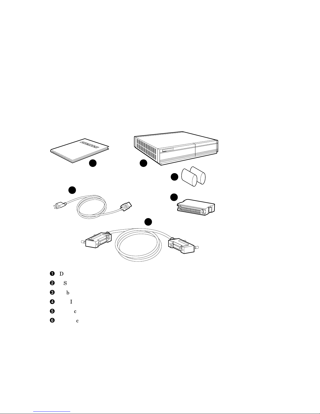
When you unpack the carton that contains a BA42 DSSI expansion box, you
will find all of the items shown in Figure 1–1.
Installing the BA42 DSSI Storage Expander 1–1
Page 10
Installing the BA42 DSSI Storage Expander
1.1 Checking the Shipment
Figure 1–1 Parts of a BA42 DSSI Expander Box Shipment
1 2
6
3
4
5
Documentation
DSSI expander box
Rubber drive shipping bracket supports (up to three)
DSSI terminator
DSSI cable
Power cord (In Europe the power cord may not be included; it is an optional
item which may be ordered from a menu.)
1–2 Installing the BA42 DSSI Storage Expander
MLO-009778
Page 11

1.2 Setting Up the Expander
It takes two people to unpack and set up a BA42 DSSI expander safely.
Standing an expander on its side blocks vents and can damage the
expander and any drives it contains.
Set up the BA42 DSSI expander on a flat surface as near as possible to the
system unit. If you are installing more than one expander, you can stack the
boxes on top of each other.
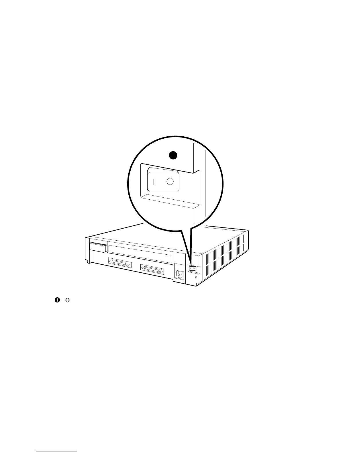
Make sure the on/off switch on the expander is in the off position (see
Figure 1–2).
Installing the BA42 DSSI Storage Expander
1.2 Setting Up the Expander
Warning
Caution
Installing the BA42 DSSI Storage Expander 1–3
Page 12
Installing the BA42 DSSI Storage Expander
1.2 Setting Up the Expander
Figure 1–2 On/Off Switch in the Off Position
1
On/off switch
1.3 Determining Which DSSI ID Numbers Are Available
A DSSI ID number must be designated for the first drive installed in a BA42
expander; the DSSI IDs for the remainder of the drives in the expander will be
set automatically in increments of one, beginning with the number assigned to
the first drive.
Numbers that can be used range from 0 to 7 (up to seven DSSI drives can be
connected to a given DSSI connector on the system unit); each number may
be used only once via that connector. To find out what DSSI ID numbers are
available, see the option installation instructions in the installation guide or
user’s guide for the system.
After determining the DSSI ID number to be assigned to the first drive, use
the DSSI ID switches on the rear of the expander box to set the ID to that
number (see Section 1.4).
1–4 Installing the BA42 DSSI Storage Expander
MLO-009779
Page 13

Installing the BA42 DSSI Storage Expander
1.4 Setting DSSI ID Switches for Hard Disk Drives
1.4 Setting DSSI ID Switches for Hard Disk Drives
The DSSI ID switch for hard disk drives installed in a BA42 expander is
located on the back of the expander.
If there are one to four hard disk drives preinstalled in your expander,
check the DSSI ID switch setting for the first drive and change the setting
if necessary. Settings for the remaining hard disks are then automatically
incremented.
1.4.1 Remove the DSSI ID Switch Cover from the Expander
Access the DSSI ID switches by lifting up and removing the switch cover (see
Figure 1–3). Replace the switch cover after checking the switches or the drive
indicator LEDs.
Installing the BA42 DSSI Storage Expander 1–5
Page 14
Installing the BA42 DSSI Storage Expander
1.4 Setting DSSI ID Switches for Hard Disk Drives
Figure 1–3 Removing the DSSI ID Switch Cover from the Expander
1.4.2 Check the DSSI ID Switch Setting on the Expander
If there is a hard disk drive installed in the expander, the three DSSI ID
switches on the back of the box determine the DSSI ID switch setting for the
first drive (see Figure 1–4).
The DSSI IDs for additional hard drives are automatically incremented by one
as they are added; no further action is necessary.
1–6 Installing the BA42 DSSI Storage Expander
MLO-010020
Page 15

Installing the BA42 DSSI Storage Expander
1.4 Setting DSSI ID Switches for Hard Disk Drives
Figure 1–4 LED Indicators and DSSI ID Switches for Hard Disk Drives
1 2
1
2 3
OPEN
LED indicators
DSSI ID switches
MLO-010042
1.4.3 Change the DSSI ID Switch Settings if Necessary
Normally the three switches are preset at the factory to the ID number zero,
with all three switches set to open (down, down, and down). However, if the
expander is ordered with a CPU that has storage embedded, the ID of the
system disk drive in the CPU is set to zero and the first drive in the expander
box is the first available ID outside of the CPU cabinet.
If necessary, use a pen or small pointed object to flip the switches to set the
DSSI ID of the first drive to the appropriate number (see Table 1–1).
Installing the BA42 DSSI Storage Expander 1–7
Page 16

Installing the BA42 DSSI Storage Expander
1.4 Setting DSSI ID Switches for Hard Disk Drives
Table 1–1 DSSI ID Numbers and Switch Settings for Hard Disk Drives in the
Expander Box
DSSI ID NUMBERS:
Drive 1 Drive 2 Drive 3 Drive 4 Switch 1 Switch 2 Switch 3
0 1 2 3 Down Down Down
1 2 3 4 Down Down Up
2 3 4 5 Down Up Down
3 4 5 6 Down Up Up
4 5 6 7 Up Down Down
5 6 7 0 Up Down Up
6 7 0 1 Up Up Down
7 0 1 2 Up Up Up
1.5 Drive Indicator Panel
The drive indicator panel is located under the DSSI switch cover (see
Figure 1–3). The number of drives present is indicated by one to four green
LEDs. The panel also lights one of four amber LEDs to indcate that a
particular drive has faulted. See Figure 1–5.
Switch Settings
1–8 Installing the BA42 DSSI Storage Expander
Page 17

Installing the BA42 DSSI Storage Expander
Figure 1–5 Drive Indicator Panel LEDs
Drive 3
3 2
Amber LEDs
(Drive Failure)
7 6
Green LEDs
(Drive OK)
4 1
8 5
1.5 Drive Indicator Panel
Drive 2
Drive 1 failure indicator (amber LED)
Drive 2 failure indicator (amber LED)
Drive 3 failure indicator (amber LED)
Drive 4 failure indicator (amber LED)
Drive 1 OK indicator (green LED)
Drive 2 OK indicator (green LED)
Drive 3 OK indicator (green LED)
Drive 4 OK indicator (green LED)
1.6 Installing an Expander
If you are adding an expander to a system that already has an expander fully
installed, turn to Section 1.7.3 for instructions on how to connect one expander
to another.
Drive 4
Drive 1
MLO-010043
Installing the BA42 DSSI Storage Expander 1–9
Page 18

Installing the BA42 DSSI Storage Expander
1.6 Installing an Expander
1.6.1 Turn Power Off
Turn off the power first to the monitor and then to the system unit.
1.6.2 Remove the Terminator from the DSSI Connector on the System
Unit
If there is a terminator on the DSSI connector on the back of the system unit,
remove it by squeezing the release tab on the sides of the terminator and
pulling the terminator out of the connector (see Figure 1–6).
Figure 1–6 Removing the DSSI Terminator from the System Unit
1
DSSI terminator
1–10 Installing the BA42 DSSI Storage Expander
MLO-010030
Page 19

Installing the BA42 DSSI Storage Expander
1.6 Installing an Expander
1.6.3 Connect the DSSI Cable to the System Unit
Figure 1–7 depicts the proper installation of a DSSI cable.
Figure 1–7 Connecting a DSSI Cable to the System Unit
1
DSSI cable
MLO-010029
Installing the BA42 DSSI Storage Expander 1–11
Page 20

Installing the BA42 DSSI Storage Expander
1.6 Installing an Expander
1.6.4 Connect the DSSI Cable to the Expander
Connect the free end of the DSSI cable to one of the connectors on the
expander. See Figure 1–8.
If you are installing more than one expander, turn to Section 1.7.3 after
connecting the DSSI cable to the first expander.
If you are installing only one box, turn to Section 1.6.5 to connect the
terminator.
Figure 1–8 Connecting a DSSI Cable to the Expander
1
DSSI cable
1–12 Installing the BA42 DSSI Storage Expander
MLO-010022
Page 21

1.6.5 Connect the Terminator
Connect the terminator to the empty connector on the expander (see
Figure 1–9).
Figure 1–9 Connecting a Terminator to the Expander
1
Installing the BA42 DSSI Storage Expander
1.6 Installing an Expander
DSSI terminator
1.6.6 Connect the Power Cord
Digital suggests that all power cords for the system be plugged into a
single source of power, such as a power strip.
Connect the prongless end of the power cord to the expander and plug the
pronged end into a power outlet or power strip (see Figure 1–10).
MLO-010031
Note
Installing the BA42 DSSI Storage Expander 1–13
Page 22

Installing the BA42 DSSI Storage Expander
1.6 Installing an Expander
After connecting the power cord, turn to Section 1.8 to verify the system
configuration.
Figure 1–10 Connecting a Power Cord to an Expander
1
Power cord
1.7 Connecting One Expander to Another Expander
This section describes attaching an expander box to a system that already has
one or more expander boxes fully installed.
1.7.1 Turn Power Off
Turn off power first to the expanders and then to the system unit.
1–14 Installing the BA42 DSSI Storage Expander
MLO-010024
Page 23

Installing the BA42 DSSI Storage Expander
1.7 Connecting One Expander to Another Expander
1.7.2 Remove the Terminator from the Expander Box
Remove the terminator from the last expander box attached to the DSSI
connector on the system unit by squeezing the release tab on the sides of the
terminator and pulling the terminator out of the connector (see Figure 1–11).
Figure 1–11 Removing a Terminator from an Expander
1
DSSI terminator
1.7.3 Connect the DSSI Expander Cable and Terminator
1. Connect the three-foot DSSI expander cable to the empty connector on the
last box connected to the system unit.
2. Connect the other end of the cable to the left-hand connector on the box
you are installing.
3. Connect the terminator to the empty connector on the final expander box.
MLO-010023
Installing the BA42 DSSI Storage Expander 1–15
Page 24

Installing the BA42 DSSI Storage Expander
1.7 Connecting One Expander to Another Expander
Figure 1–12 shows how to connect the three-foot DSSI expander cable and the
terminator.
Figure 1–12 Connecting the Three-Foot DSSI Cable and Terminator to the
Final Expander
1
Three-foot DSSI cable
DSSI terminator
2
MLO-010026
1.7.4 Connect the Power Cords
Digital suggests that all power cords for the system be plugged into a
single source of power, such as a power strip.
1–16 Installing the BA42 DSSI Storage Expander
Note
Page 25

Installing the BA42 DSSI Storage Expander
1.7 Connecting One Expander to Another Expander
Connect the prongless end of a power cord to each expander box and plug the
pronged end of each cord into a power outlet or power strip as depicted in
Figure 1–13.
Figure 1–13 Connecting Power Cords to Expander Boxes
1
Power cord
MLO-010027
Installing the BA42 DSSI Storage Expander 1–17
Page 26

Installing the BA42 DSSI Storage Expander
1.8 Verifying the System Configuration
1.8 Verifying the System Configuration
Use the following section to verify the configuration of the system.
1.8.1 Turn Power On
Turn on the power first to all expansion boxes and then to the system unit.
1.8.2 Check the Configuration Display
The configuration display for the system tells you whether the system
recognizes the drives in the expander boxes.
To display and read the system configuration, follow the instructions provided
in the hardware installation guide or user’s guide that came with the system.
If an expander box drive does not appear in the configuration display, follow
this procedure:
1. Press the on/off switch on the expander to be sure the switch is securely in
the on position.
2. Turn off the system unit and expander boxes.
3. Be sure all expander box cables are connected securely.
4. Be sure all power cords are connected securely.
5. Be sure the DSSI terminator is attached securely to the expander box.
6. Be sure the internal cables are connected securely to the drive.
7. Check the expander box cable connector for damaged pins.
8. Check the DSSI ID switch settings.
9. Check the drive indicator lights.
10. Turn on all expander boxes and the system unit; then check the
configuration display again.
11. If the configuration display still does not show the drives in the expander
box, contact the system manager or Digital service representative.
Once DSSI ID switch settings for the hard disk drives installed in the
expansion box are recognized by the system, replace the cover on the DSSI ID
switch on the back of the expander box by inserting the notch on the bottom of
the cover into the opening below the switch on the back of the expander box,
and snapping the cover into place.
1–18 Installing the BA42 DSSI Storage Expander
Page 27

Installing a BA42 Storage Expander
Use this chapter in lieu of the Installation Guide, EK–RF31T–IN,
supplied with the RF3x-EK option shipment.
This chapter includes the following topics:
• Checking the shipment to make sure nothing is broken or missing
• Installing a hard disk drive inside an expander box
2.1 Checking the Shipment
In addition to the items that make up the shipment, you will need a
Phillips screwdriver.
2
Upgrade
Note
Note
If you ordered an RF3x-EK hard disk drive, the shipment will include in
addition to the drve:
• Drive mounting bracket
• Four rubber mounts with integral screws
If any item is broken or missing, contact the system manager or Digital service
representative.
Installing a BA42 Storage Expander Upgrade 2–1
Page 28

Installing a BA42 Storage Expander Upgrade
2.2 Preparing the Expander Box
2.2 Preparing the Expander Box
Caution
To prevent damage to equipment, take the following precautions:
• Only qualified service personnel should remove the cover or install
drives.
• Static electricity can damage integrated circuits. Always use a
grounded wrist strap and a grounded work surface (29–26246)
when working with the internal parts of a computer system.
• Shut down the operating system in an orderly fashion before you
remove or install drives; the procedures in this document assume
that the operating system has been shut down first.
• Turn off the system power before you remove or install drives (see
Section 2.2.1).
Prepare the expander box for the addition of a drive:
1. Turn off all power (Section 2.2.1).
2. Remove the cover (Section 2.2.2).
2.2.1 Turn Power Off
Turn off power first to all expander boxes, then to the system unit, and remove
the power cord from the expander box to be upgraded.
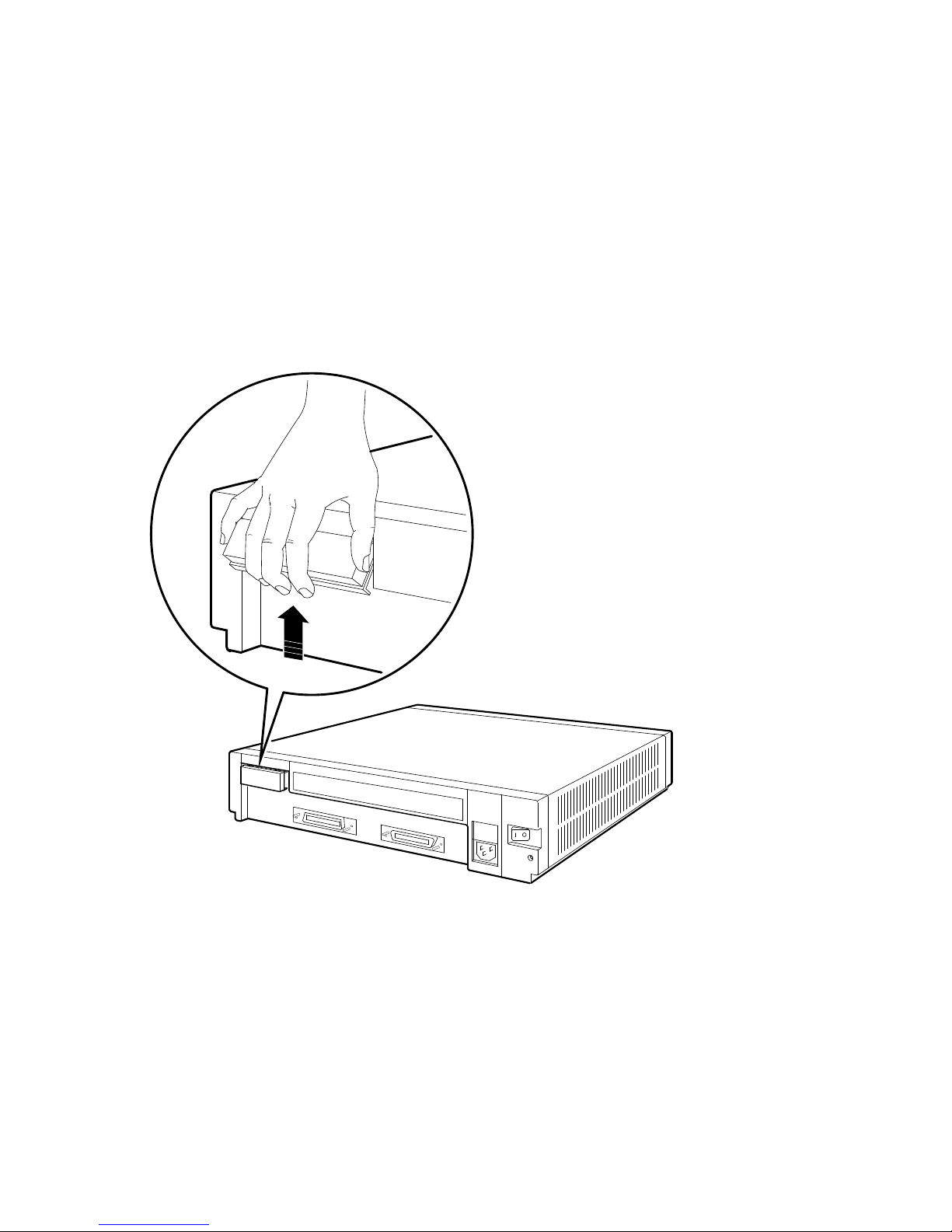
2.2.2 Remove the Cover from the Expander Box
Loosen the two cover release screws on the back of the expander. Grasp each
side of the cover and pull it toward you (see Figure 2–1). Then pull the cover
up and away from the box.
2–2 Installing a BA42 Storage Expander Upgrade
Page 29

Installing a BA42 Storage Expander Upgrade
2.2 Preparing the Expander Box
Figure 2–1 Removing the Cover from the Expander Box
1
Cover release screws
2.3 Installing an RF3x-EK Hard Disk Drive
These are the general steps to install a hard disk drive in the BA42 expander
box:
• Attach the drive bracket and shock isolator rubber feet (see Section 2.3.1).
• Determine the appropriate location (see Section 2.3.2).
• Connect the DSSI signal cable (see Section 2.3.3).
• Connect the power cable (see Section 2.3.4).
• Connect the Remote Front Panel (RFP) cable (see Section 2.3.5).
• Install the drive in the expander box (see Section 2.3.6).
MLO-010048
Installing a BA42 Storage Expander Upgrade 2–3
Page 30

Installing a BA42 Storage Expander Upgrade
2.3 Installing an RF3x-EK Hard Disk Drive
2.3.1 Attach the Drive Bracket and Shock Isolator Rubber Feet
Using a Phillips screwdriver, attach the drive bracket and four shock isolator
rubber feet to the drive as shown in Figure 2–2.
Figure 2–2 Drive Bracket
2
Shock isolator rubber foot
Drive bracket
2–4 Installing a BA42 Storage Expander Upgrade
1
MLO-010045
Page 31

Installing a BA42 Storage Expander Upgrade
2.3 Installing an RF3x-EK Hard Disk Drive
2.3.2 Determine the Drive Location
Each RF3x-EK hard disk drive must be placed in a specific location within the
BA42 expander box. Figure 2–3 shows the appropriate location for the first
and all subsequent drives.
Figure 2–3 Drive Locations Inside the BA42 Expander Box
1
2
2.3.3 Connect the 50-Pin DSSI Cable
Connect the appropriate 50-pin DSSI connector to the drive (see Figure 2–4).
The keyed tab on the bottom of the connector slides into the corresponding slot
on the drive. The drive must only be attached to the DSSI signal cable with
the appropriate connector for that drive (see Figure 2–5 to determine which
connector to use for each drive).
4
3
MLO-010032
Installing a BA42 Storage Expander Upgrade 2–5
Page 32

Installing a BA42 Storage Expander Upgrade
2.3 Installing an RF3x-EK Hard Disk Drive
Figure 2–4 Connecting 50-Pin DSSI Signal Cable
1
Signal cable
2–6 Installing a BA42 Storage Expander Upgrade
MLO-010034
Page 33

Installing a BA42 Storage Expander Upgrade
2.3 Installing an RF3x-EK Hard Disk Drive
Figure 2–5 50-Pin DSSI Signal Cable in the Expander Box
1
Signal cable
1
2
4
3
MLO-010035
Installing a BA42 Storage Expander Upgrade 2–7
Page 34

Installing a BA42 Storage Expander Upgrade
2.3 Installing an RF3x-EK Hard Disk Drive
2.3.4 Connect the 5-Pin Power Cable
Connect the appropriate 5-pin power connector to the drive. The keyed tab
on top of the connector slides into the corresponding slot on the drive, as
shown in Figure 2–6. The drive must only be attached to the power cable with
the appropriate connector for that drive (see Figure 2–7 and Figure 2–8 to
determine which connector to use for each drive).
The connections to the Remote Front Panel (RFP) detailed in Figure 2–7
and Figure 2–8 will already be in place; they are included here as an aid in
troubleshooting.
Figure 2–6 Connecting the 5-Pin Power Cable
Power cable
2–8 Installing a BA42 Storage Expander Upgrade
1
MLO-010036
Page 35

Installing a BA42 Storage Expander Upgrade
2.3 Installing an RF3x-EK Hard Disk Drive
Figure 2–7 Power Cables for Drives 1 and 4 in the Expander Box
2
1
3
Drive 1 power cable
RFP connectors
Drive 4 power cable
1
4
MLO-010037
Installing a BA42 Storage Expander Upgrade 2–9
Page 36

Installing a BA42 Storage Expander Upgrade
2.3 Installing an RF3x-EK Hard Disk Drive
Figure 2–8 Power Cables for Drives 2 and 3 in the Expander Box
2
1
Drive 2 power cable
RFP connector
Drive 3 power cable
2–10 Installing a BA42 Storage Expander Upgrade
3
2 3
MLO-010038
Page 37

Installing a BA42 Storage Expander Upgrade
2.3 Installing an RF3x-EK Hard Disk Drive
2.3.5 Connect the 12-Pin RFP Cable
The Remote Front Panel cables will already be in place on the RFP. Attach the
appropriate RFP cable to the drive. The cable is attached so that it extends
downward from the drive as shown in Figure 2–9. The drive must only be
attached to the appropriate RFP cable for that drive (see Figure 2–10 to
determine which cable to use for each drive).
Figure 2–9 Connecting the RFP Cable
RFP cable
1
MLO-010039
Installing a BA42 Storage Expander Upgrade 2–11
Page 38

Installing a BA42 Storage Expander Upgrade
2.3 Installing an RF3x-EK Hard Disk Drive
Figure 2–10 RFP Cables in the Expander Box
J1
J2
1
J3
J4
1
4
2
2 3
RFP cables for drives 1 and 2
RFP cables for drives 4 and 3
2–12 Installing a BA42 Storage Expander Upgrade
MLO-010040
Page 39

Installing a BA42 Storage Expander Upgrade
2.3 Installing an RF3x-EK Hard Disk Drive
2.3.6 Install the Drive in the Expander Box
Tilt the drive until you can place the shock isolator rubber feet on the bottom
of the drive into the four keyhole-shaped openings in the floor of the box. See
Figure 2–11.
Figure 2–11 Inserting an RF3x-EK Hard Disk Drive in the Expander Box
1
Shock isolator rubber foot
Slide the drive toward the small end of the keyhole-shaped openings so that
the slots on the shock isolator rubber feet engage the hole, and the metal
spring tab on the expander box floor fits into the appropriate slot on the drive
bracket (see Figure 2–12).
Support is required if the expander box is to be shipped or moved; in
that case, insert a rubber drive shipping bracket support (shown in
Figure 2–12) into the metal retaining slot for each drive.
MLO-010046
Note
Installing a BA42 Storage Expander Upgrade 2–13
Page 40

Installing a BA42 Storage Expander Upgrade
2.3 Installing an RF3x-EK Hard Disk Drive
Figure 2–12 Fastening an RF3x-EK Hard Disk Drive in the Expander Box
Metal spring tab
Rubber drive shipping bracket support
1
2
MLO-010047
2.3.7 Replace the Cover on the Expander Box
Position the cover so it rests on top of the box about 3 inches short of the back
of the box. Move the cover straight toward the back of the box until it slips
into place (see Figure 2–13). Tighten the two cover release screws on the back
of the box and plug in the power cord.
Caution
Make sure the internal cables are pushed down into the box before
replacing the cover. Closing the cover on the cables may damage the
cables.
2–14 Installing a BA42 Storage Expander Upgrade
Page 41

Installing a BA42 Storage Expander Upgrade
2.3 Installing an RF3x-EK Hard Disk Drive
Figure 2–13 Replacing the Cover on the BA42 Expander
1
Cover release screws
2.4 DSSI ID Switch Settings
The three DSSI ID switches on the back of the box determine the DSSI ID
switch setting for the first drive (see Section 1.4).
The DSSI IDs for additional hard drives are automatically incremented by one
as the drives are added and brought on line; no further action is necessary. To
verify the system configuration, see Section 1.8.
MLO-010049
Installing a BA42 Storage Expander Upgrade 2–15
Page 42

Page 43

Reader’s Comments BA42 DSSI Expander Installation Manual
EK–BA42C–IN. A01
Your comments and suggestions help us improve the quality of our publications.
Please rate the manual in the
following categories: Excellent Good Fair Poor
Accuracy (product works as described)
Completeness (enough information)
Clarity (easy to understand)
Organization (structure of subject matter)
Figures (useful)
Examples (useful)
Table of contents (ability to find topic)
Index (ability to find topic)
Page design (overall appearance)
Print quality
What I like best about this manual:
What I like least about this manual:
Additional comments or suggestions:
I found the following errors in this manual:
Page Description
For which tasks did you use this manual?
Installation Programming
Maintenance System Management
Marketing Training
Operation/Use Other (please specify)
Name/Title
Company
Address
Page 44

Do Not Tear – Fold Here and Tape
BUSINESS REPLYMAIL
FIRST CLASS PERMIT NO. 33 MAYNARD MASS.
POSTAGE WILL BE PAID BY ADDRESSEE
DIGITAL EQUIPMENT CORPORATION
INFORMATION DESIGN AND CONSULTING
PKO3–1/D30
129 PARKER STREET
MAYNARD, MA 01754–9975
NO POSTAGE
NECESSARY
IF MAILED
IN THE
UNITED STATES
Do Not Tear – Fold Here and Tape
 Loading...