

Page 1

AlphaServer 1000A
Owner's Guide
Order Number: EK–ALPSV–OG. A02
Digital Equipment Corporation
Maynard, Massachusetts
Page 2

February 1996
October 1996
Digital Equipment Corporation makes no representations that the use of its products in the manner
described in this publication will not infringe on existing or future patent rights, nor do the
descriptions contained in this publication imply the granting of licenses to make, use, or sell
equipment or software in accordance with the description.
Possession, use, or copying of the software described in this publication is authorized only pursuant
to a valid written license from Digital or an authorized sublicensor.
Copyright Digital Equipment Corporation, 1996. All Rights Reserved.
The following are trademarks of Digital Equipment Corporation:
Alpha, AlphaGeneration, DEC, DECchip, Digital, OpenVMS, OpenVMS Alpha, and the DIGITAL
logo.
Digital UNIX Version 3.0 is an X/Open UNIX 93 branded product.
The following are third party trademarks:
Microsoft is a registered trademark, and Microsoft Windows and Microsoft Windows NT are
trademarks of Microsoft Corporation.
OSF/1 is a trademark of the Open Software Foundation, Inc.
PostScript is a trademark of Adobe Systems, Inc.
All other trademarks and registered trademarks are the property of their respective holders.
S3379
FCC ID: AO9-PB702
FCC NOTICE:
digital device, pursuant to Part 15 of the FCC rules. These limits are designed to provide reasonable
protection against harmful interference in a residential installation.
Any changes or modifications made to this equipment may void the user's authority to operate this
equipment.
This equipment generates, uses, and can radiate radio frequency energy and, if not installed and used
in accordance with the instructions, may cause harmful interference to radio communications.
However, there is no guarantee that interference will not occur to radio or television reception. If
this equipment does cause harmful interference to radio or television reception, which can be
determined by turning the equipment off and on, the user is encouraged to try to correct the
interference by one or more of the following measures:
- Reorient or relocate the receiving antenna.
- Increase the separation between the equipment and receiver.
- Connect the equipment into an outlet on a circuit different from that to which the receiver is
connected.
- Consult the dealer or an experienced radio/TV technician for help.
This equipment has been tested and found to comply with the limits for a Class B
Page 3
The user may find the following booklet prepared by the Federal Communications Commission
helpful: How to Identify and Resolve Radio-TV Interference Problems. This booklet is available from
the U.S. Government Printing Office, Washington, D.C., 20402. Stock No. 004-00398-5.
All external cables connecting to this basic unit need to be shielded. For cables connecting to option
boards, see the option manual or installation instructions.
This digital apparatus does not exceed the Class B limits for radio noise emissions set out in the
radio interference regulations of the Canadian Department of Communications.
ACOUSTIC DECLARATION:
AlphaServer 1000A
(PB73A-A9/PB74A-A9)
Idle
Operating
Preliminary declared values per ISO 9296 and ISO 7779:
LwAd, B LpAm, dBA
(Bystander Positions)
5.6
5.6
36
36
AlphaServer 1000A
(PB73A-A9/PB74A-A9) with
6xRZ26L
Idle
Operating
Current values for specific configurations are available from Digital representatives. 1 B = 10 dBA.
5.7
5.8
38
39
Page 4

Page 5

Contents
Preface
About This Guide..............................................................................................................xi
Purpose and Audience.........................................................................................xi
Before You Use This Guide.................................................................................xi
Reader's Comment's ............................................................................................xi
Online Version....................................................................................................xi
Organization.....................................................................................................xiii
Conventions....................................................................................................................xiv
Related Documentation.................................................................................................... xv
1 Overview
Introduction....................................................................................................................1-1
System Overview ............................................................................................................1-1
Supported Operating Systems............................................................................1-2
System Console Firmware.................................................................................1-2
System Features................................................................................................. 1-4
Front Panel Controls and Indicators ..................................................................1-6
Rear Panel Ports and Slots.................................................................................1-9
Internal System Options..................................................................................1-10
External Options.............................................................................................1-12
Ordering Options ............................................................................................1-12
2 Hardware Installation
Introduction....................................................................................................................2-1
Hardware Setup Overview...............................................................................................2-1
Selecting a System Location............................................................................................2-2
Environmental Conditions.................................................................................2-2
Power Requirements..........................................................................................2-4
Identifying Accessories ................................................................................................... 2-6
Optional Accessories.........................................................................................2-7
Connecting a Keyboard, Mouse, or Printer......................................................................2-7
Connecting a Monitor or Terminal..................................................................................2-8
AlphaServer 1000A Owner's Guide Contents • v
Page 6

Connecting to Network Hardware...................................................................................2-8
Verifying Hardware Setup...............................................................................................2-9
Locking Your System ................................................................................................... 2-11
Recording the System Unit Key Number .........................................................2-12
3 Preparing to Install an Operating System
Introduction....................................................................................................................3-1
Preparing to Install Windows NT....................................................................................3-2
Preparing the System ........................................................................................3-2
Installing Microsoft Windows NT.....................................................................3-7
Preparing to Install Digital UNIX...................................................................................3-7
Installation Preparation.....................................................................................3-7
Installing Digital UNIX ....................................................................................3-8
Preparing to Install OpenVMS Alpha.............................................................................3-8
Preparing the System ........................................................................................3-8
Installing OpenVMS Alpha............................................................................. 3-10
4 Basic Operation
Introduction....................................................................................................................4-1
Turning the System On................................................................................................... 4-1
Turning the System Off ..................................................................................................4-3
Accessing the System from a Remote Location ...............................................................4-4
Interpreting Startup Messages.........................................................................................4-5
Reading the Startup Test Results.......................................................................4-7
Using the Consoles .........................................................................................................4-8
Invoking Console Mode ....................................................................................4-8
When to Switch Consoles..................................................................................4-8
Switching to the Digital UNIX and OpenVMS Alpha (SRM) Console...............4-9
Switching to the Windows NT (ARC) Console..................................................4-9
Windows NT (ARC) Console Menus............................................................... 4-10
Digital UNIX and OpenVMS Alpha (SRM) Console Commands ....................4-11
SRM Console Security Features.......................................................................4-13
Getting Help on the Windows NT (ARC) Console........................................... 4-15
Getting Help on the Digital UNIX and OpenVMS Alpha (SRM) Console ....... 4-17
Booting the Operating System.......................................................................................4-19
Booting Windows NT......................................................................................4-23
Booting Digital UNIX or OpenVMS Alpha Operating Systems....................... 4-25
Using Storage Drives.................................................................................................... 4-26
Using a Diskette Drive....................................................................................4-28
Using a CDROM Drive...................................................................................4-29
Using a StorageWorks Disk Drive...................................................................4-32
Caring for Your System................................................................................................ 4-32
vi • Contents AlphaServer 1000A Owner's Guide
Page 7

Cleaning Your System Unit............................................................................. 4-32
Cleaning Your Mouse .....................................................................................4-32
Cleaning Your Keyboard.................................................................................4-33
Moving Your System.......................................................................................4-33
Packing Your System ......................................................................................4-33
Installing Your System at a New Location.......................................................4-33
5 Installing and Removing Components
Introduction....................................................................................................................5-1
Preparing to Install or Remove Components....................................................................5-2
Required Equipment..........................................................................................5-2
Antistatic Precautions........................................................................................5-2
Top Cover and Side Panels .............................................................................................5-3
Removing the Top Cover and Side Panels .........................................................5-3
Replacing the Top Cover and Side Panels..........................................................5-5
Memory Modules............................................................................................................5-6
Removing Memory Modules..............................................................................5-7
Installing Memory Modules...............................................................................5-8
PCI, EISA, and ISA, Option Cards ...............................................................................5-10
Installing an Option Card................................................................................5-11
Removing an Option Card...............................................................................5-13
Testing an Option Card Installation.................................................................5-14
Configuring an Option Card............................................................................ 5-16
Network Interface Card...................................................................................5-16
Storage Devices ............................................................................................................5-16
Identifying the Drive Bays............................................................................... 5-17
Installing a Tape Drive.................................................................................... 5-18
Removing a Tape Drive...................................................................................5-19
Installing a CDROM Drive..............................................................................5-20
Removing a CDROM Drive.............................................................................5-20
Installing a StorageWorks Disk Drive ............................................................. 5-20
Installing a Diskette Drive...............................................................................5-22
Removing a Diskette Drive..............................................................................5-23
Power Supply................................................................................................................5-24
CPU Card ..................................................................................................................... 5-27
6 Configuring
Introduction....................................................................................................................6-1
Viewing the System Configuration..................................................................................6-1
ARC Console Configuration Options.................................................................6-2
SRM Console Configuration Commands...........................................................6-4
Memory........................................................................................................................6-11
AlphaServer 1000A Owner's Guide Contents • vii
Page 8

Network Connections....................................................................................................6-12
Power Supply................................................................................................................ 6-12
Keyboard Type..............................................................................................................6-13
EISA and ISA Options.................................................................................................. 6-14
PCI Option Cards .........................................................................................................6-22
Storage Devices ............................................................................................................6-23
7 Upgrading
Introduction....................................................................................................................7-1
Planning Your Upgrade..................................................................................................7-1
Upgrade Options.............................................................................................................7-4
Setting Network Configuration........................................................................6-12
EISA Bus........................................................................................................6-14
ISA Bus ..........................................................................................................6-15
EISA Configuration Utility (ECU) ..................................................................6-16
Configuring EISA Options..............................................................................6-18
Configuring ISA Options................................................................................6-20
Determining SCSI Storage Device IDs............................................................ 6-23
On-board SCSI Bus Configuration..................................................................6-25
Rules for Configuring SCSI Controller Option Cards...................................... 6-25
SCSI Device Configurations............................................................................6-26
Single-Controller Configuration...................................................................... 6-28
Dual-Controller Configuration........................................................................6-31
Dual-Controller, Split-Backplane Configuration..............................................6-34
Triple-Controller, Split-Backplane Configuration............................................6-37
Access from the Internet....................................................................................7-3
Digital Systems and Options Catalog ................................................................7-3
Firmware ..........................................................................................................7-4
Updating Firmware Using the CDROM Drive...................................................7-5
Updating Firmware Using the Network.............................................................7-6
Updating Firmware Using the Diskette Drive....................................................7-6
8 Troubleshooting
Introduction....................................................................................................................8-1
Troubleshooting Overview..............................................................................................8-2
System Diagnostics.........................................................................................................8-3
Interpreting Error Beep Codes...........................................................................8-3
Reading the Console Event Log.........................................................................8-4
The test Command............................................................................................8-4
The kill and kill_diags Commands.................................................................... 8-7
The show_status Command...............................................................................8-7
Power Problems..............................................................................................................8-8
viii • Contents AlphaServer 1000A Owner's Guide
Page 9

Console Problems ...........................................................................................................8-8
Boot Problems...............................................................................................................8-10
Problems Detected by the Operating System..................................................................8-12
Storage Problems..........................................................................................................8-13
Option Card Problems...................................................................................................8-15
Network Problems...........................................................................................8-15
EISA/ISA Bus Problems..................................................................................8-15
PCI Bus Problems ...........................................................................................8-16
Monitor and Terminal Problems ...................................................................................8-17
Keyboard and Mouse Problems .....................................................................................8-19
Printer Problems...........................................................................................................8-19
Overheating Problems................................................................................................... 8-20
RAID Device Problems.................................................................................................8-20
Using the Fail-Safe Loader............................................................................................8-21
9 Quick Reference
Introduction....................................................................................................................9-1
Messages ........................................................................................................................9-1
Hardware Overview ........................................................................................................9-2
System Front View............................................................................................9-2
System Rear View.............................................................................................9-3
System Side View..............................................................................................9-4
System Board Connectors, Chips, and Slots.......................................................9-6
Port Pinouts.......................................................................................................9-7
Indicator Lights ............................................................................................................9-11
System Board and CPU Card Jumper Settings...............................................................9-12
SCSI ID Settings...........................................................................................................9-17
Single-Controller Configuration Jumper Options.............................................9-17
Dual-Controller Configuration Jumper Options...............................................9-18
Triple-Controller Configuration Jumper Options.............................................9-19
Specifications................................................................................................................9-20
System Architecture......................................................................................................9-22
Glossary of Terms
Index
AlphaServer 1000A Owner's Guide Contents • ix
Page 10

Page 11

Preface
About This Guide
Purpose and Audience
This guide describes how to set up, operate, troubleshoot, and maintain your server
system. This information is intended for users, system managers, and others who
perform system management tasks.
Before You Use This Guide
If you have not already installed the system, refer to the installation card shipped
with the system and to Chapter 2, "Hardware Installation," in this guide. Some
procedures in this document require that you refer to your operating system
documentation. Please have your operating system documentation available for use
with this guide.
Reader's Comment's
Digital welcomes your comments on this or any other manual. You can send your
comments in the following ways:
Internet electronic mail to:
Mail to: Digital Equipment Corporation
Shared Engineering Services
129 Parker Street
PKO3-2/A9
Maynard, MA 01754-2199
Online Version
Your system shipment should include documentation on a CDROM. This CD
contains an easy-to-navigate, electronic version of the information in this printed
AlphaServer 1000A Owner's Guide Preface • xi
readers_comment@zk3.dec.com
Page 12

user's guide, plus an additional resource guide. You can install the CDROM on any
personal computer running Microsoft Windows 3.1 or later, Microsoft Windows NT
3.1, or a Windows emulator. The disk on which you install the CDROM must have
approximately four megabytes of free space available.
Organization
This guide is organized as follows:
The Preface provides an overview of this guide.
Chapter 1, "Overview," provides an overview of the system features and
capabilities.
Chapter 2, "Hardware Installation," provides instructions for installing your
system hardware.
Chapter 3, "Preparing to Install an Operating System," explains how to prepare
your system for installation of an operating system.
Chapter 4, "Basic Operation," describes how to turn the system on and off,
interpret startup messages, use console mode, boot an operating system, and use
storage devices.
Chapter 5, "Installing and Removing Components," explains how to install and
remove internal system components and options.
Chapter 6, "Configuring," describes how to configure the system.
Chapter 7, "Upgrading," describes how to plan for upgrading the system with
additional memory, network connections, power supply, options, and firmware.
Chapter 8, "Troubleshooting," explains how to identify and solve system
problems and how to perform diagnostics.
Chapter 9, "Quick Reference" contains system messages, jumper settings, SCSI
ID settings, specifications, and the system diagram.
The Glossary defines technical terms related to the system.
The Index provides a listing of main topics in this guide.
xii • Preface AlphaServer 1000A Owner's Guide
Page 13
Conventions
The following table lists the typographical conventions used in this guide.
Convention Meaning
x
Ctrl/
Warning:
Caution:
Note:
boot
show config
[ ] In command descriptions, brackets indicate
{ } In command descriptions, braces containing
< > In console mode online help, angle brackets
italic type
1
Ctrl/x indicates that you hold down the Ctrl key
while you press another key, indicated here by x.
Warnings contain information to prevent
personal injury.
Cautions provide information to prevent damage
to equipment or software.
Notes provide important additional information
that you may need when performing certain
procedures.
Commands that you enter are shown in this
special typeface. Commands shown in lowercase
letters can be entered in either uppercase or
lowercase. Commands shown in uppercase
letters must be entered in uppercase for the
command to work.
Console command abbreviations must be entered
exactly as shown.
optional elements.
items separated by commas indicate mutually
exclusive items.
enclose a placeholder for which you must specify
a value.
Italic type in console command sections indicates
a variable.
In figures, a numbered callout labels a part of a
figure. In text, the numbered callout refers to a
labeled part of a corresponding figure.
AlphaServer 1000A Owner's Guide Preface • xiii
Page 14
Related Documentation
This section lists related documents that you may find helpful when operating your
system or adding options.
To Learn More about the System:
Document Part Number
Alpha Architecture Concepts
Alpha Architecture Concepts
(Digital UNIX)
(OpenVMS Alpha)
EY-N389E
EY-K725E
To Install the System:
Document Part Number
AlphaServer 1000A Basic Installation Card
DEC OSF/1 AXP Factory Installed Software
User Information
OpenVMS Factory Installed Software User
Information
EK-ALPSV-IN
EK-SFFIS-UG
EK-A0377-UG
To Install and Operate Options:
Document Part Number
RRD45 CDROM Disc Drive Operating Guide
TZK11 Tape Backup System User's Guide
StorageWorks RAID Array 200 Subsystem
Family Installation and Configuration Guide
EK-RRDDD-IN
EK-TZK11-UG
EK-SWRA2-IG
To Service the System:
Document Part Number
AlphaServer 1000A Service Guide
AlphaServer 1000A Illustrated Parts Breakdown
xiv • Preface AlphaServer 1000A Owner's Guide
EK-ALPSV-SV
EK-ALPSV-IP
Page 15

1 Overview
Introduction
This chapter provides an overview of your system features and capabilities. The
following topics are covered:
System Overview
Supported Operating Systems
Console Firmware
System Features
Front Panel Controls and Indicators
Rear Panel Ports and Slots
Internal System Options
External Options
Ordering Options
System Overview
This high-performance, single-processor system is intended for use as a local area
network (LAN) server or commercial applications server. It is housed in a deskside
enclosure, which is divided into two sides. One side contains components: the
system board, CPU card, other logic modules, and fans. The other side contains up
to two power supplies and a StorageWorks backplane. The system uses the
DECchip 21064 and DECchip 21064A RISC microprocessors based on the Alpha
architecture, and provides all the power of a 64-bit computing environment. The
Alpha Privileged Architecture Library code (PALcode) supports multiple operating
environments that offer a choice of applications.
AlphaServer 1000A Owner's Guide Overview • 1-1
Page 16

This system is intended for the following types of uses:
As an applications server, running relational databases, electronic mail,
communications, or other applications
As a print server, providing common printing resources to PCs and other systems
in a LAN
As a file server, providing disk storage to PCs and other systems in a LAN
As a compute server, displaying the output of applications that you run remotely
on the server
Supported Operating Systems
This system supports the following operating systems:
Microsoft Windows NT
OpenVMS Alpha
Digital UNIX (DEC OSF/1)
While the operating system is running, it controls the system, which is in program
mode. When the operating system is not running, a second mode, console mode,
allows you to control system management functions, described in the next section.
System Console Firmware
You perform many of the tasks for managing and configuring your server system in
console mode, where the system is controlled by the console subsystem, rather than
the operating system.
The console subsystem, located in ROM (read-only memory) on the system board,
contains special software, called firmware, that interacts directly with hardware
components and facilitates interaction between the system hardware and the
operating system.
Because the system is designed to support multiple operating systems, it offers two
separate interfaces to the console subsystem. The Windows NT operating system is
supported by the Advanced RISC Computing (ARC) console. The OpenVMS Alpha
and Digital UNIX operating systems are supported by the Alpha System Reference
Manual (SRM) console. Regardless of the operating system you use, you may need
to access both consoles, depending on the particular task.
Console Firmware Tasks
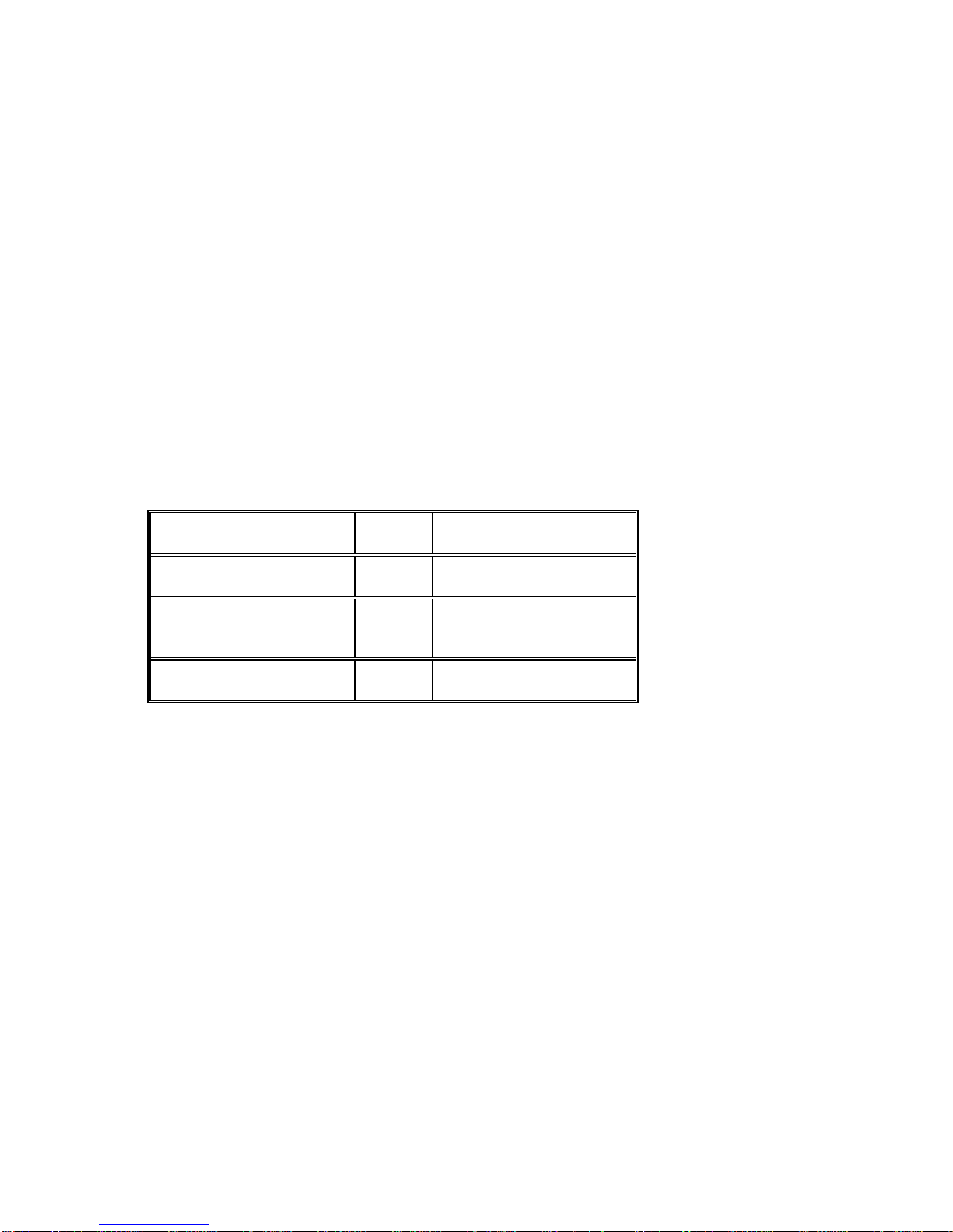
The console firmware allows you to perform the tasks listed in Table 1-1 through
either the ARC or the SRM console. The Windows NT (ARC) console firmware has
1-2 • Overview AlphaServer 1000A Owner's Guide
Page 17
a menu-based interface designed to facilitate hardware interaction with the Windows
NT operating system. The OpenVMS Alpha and Digital UNIX (SRM) console
firmware has a command line interface for hardware interaction with the Digital
UNIX or OpenVMS Alpha operating systems.
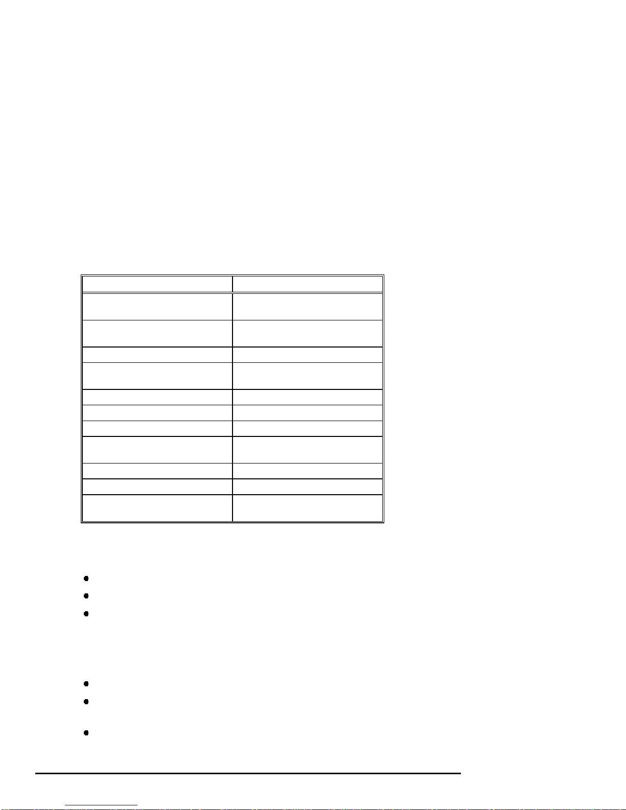
Table 1-1 Console Firmware Tasks
You Are Using... And You Want to... Console to Use
Windows NT Boot Windows NT ARC
Run the EISA Configuration Utility ARC
Run an adapter configuration utility ARC
Update firmware ARC
Switch to the SRM console ARC
Run programs written to run within the ARC firmware ARC
List Windows NT device names ARC
Digital UNIX or
OpenVMS Alpha
Change Windows NT boot configurations and
environment variables
Initialize the system ARC
Display system configuration ARC
Perform diagnostic tests SRM
Boot Digital UNIX or OpenVMS Alpha SRM
Update firmware SRM
Switch to Windows NT console SRM
Initialize the system SRM
Display system configuration SRM
Display system storage devices SRM
Set and display environment variables specific to
Digital UNIX and OpenVMS Alpha
Set and display environment variables that are common
to Digital UNIX, OpenVMS Alpha and Windows NT
Set console security SRM
Perform diagnostic tests SRM
Run the RAID Configuration Utility SRM command
Run the EISA Configuration Utility SRM command
ARC
SRM
SRM
invokes ARC
invokes ARC
AlphaServer 1000A Owner's Guide Overview • 1-3
Page 18

System Features
The system provides a number of special features that enhance its reliability, ensure
its availability, and improve its expansion capabilities, as well as facilitate hardware
management and improve security.
Reliability/Availability
•
64-bit Alpha RISC architecture Provides significantly better performance
•
Error Correction Code (ECC)
memory and CPU cache
•
Dual SCSI backplanes
•
Second power supply
•
Variable fan speed
•
Internal sensors
System Expansion
•
Flexible memory architecture
•
Seven PCI expansion slots, and
two EISA expansion slots
•
Integrated Fast Wide SCSI-2
controller with external SCSI-2
connector
•
Integrated SVGA controller
than 32-bit architecture.
Allows recovery from most cache and
memory errors.
One SCSI controller for each backplane
allows fully redundant disk subsystems.
Provides redundant power as backup.
Adjusts fan speed according to system
temperature.
Monitor and detect internal system
temperature, fan failure, power supply
temperature.
Provides a 128-bit data path with ECC
protection. System memory can be
upgraded from 16 MB to 1 GB using
memory options.
Accommodates industry-standard option
cards such as Ethernet, FDDI, SCSI, and
modems.
Supports tape, CDROM and hard disk
drives without use of an expansion slot.
Supports management and configuration
applications locally without use of an
expansion slot.
1-4 • Overview AlphaServer 1000A Owner's Guide
Page 19

• Capacity for 10 internal storage
devices
• External ports
• Wide-ready SCSI backplane
• Hot swap disk capability
Server Management
• System diagnostics
• Hardware configuration
• Unique asset management
• RAM-based error log
• Firmware upgrade utility
• Hard drive indicator lights
Accommodates one StorageWorks modular
storage system, which supports up to seven
3½-inch SCSI drives. The system also
supports up to two 5½-inch, half-height
drives (CDROM or tape), and one 3½-inch
diskette drive.
Two serial ports and one parallel port
support external options such as a printer,
modem or local terminal.
Provides high-performance drive
technology.
Allows replacement of StorageWorks disk
drives while the system continues to
operate.
Allows local and remote diagnosis of system
problems.
Allows local and remote system
configuration.
Unique system identifier in nonvolatile
memory provides easy asset management.
Records startup error messages.
Provides loading and verification of
firmware versions.
Provide immediate status information on
hard drive activity or failure.
System Security
• Key lock
• Security loop (on rear of system
unit)
• Interlock sensor switch
AlphaServer 1000A Owner's Guide Overview • 1-5
Limits access to system components.
Allows system to be secured in place.
Automatically turns off system power if the
top cover is removed while power is on.
Page 20
Front Panel Controls and Indicators
The controls and indicators on the front panel of the system unit are shown in Figure
1-1 and described in Table 1-2.
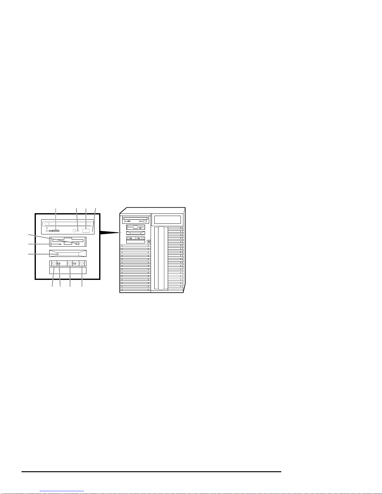
Figure 1-1 shows the locations of the controls and indicators on the front panel of the
system unit.
Figure 1-1 Front Panel Indicators
8 9 10 11
7
6
5
432 1
MA00904
1 Halt switch
2 Reset switch
3 On/Off indicator
4 On/Off switch
5 Operator control panel
6 Diskette drive activity indicator
7 Diskette drive eject button
8 CDROM volume control
9 CDROM activity indicator
10 CDROM eject button
11 CDROM emergency eject hole
1-6 • Overview AlphaServer 1000A Owner's Guide
Page 21
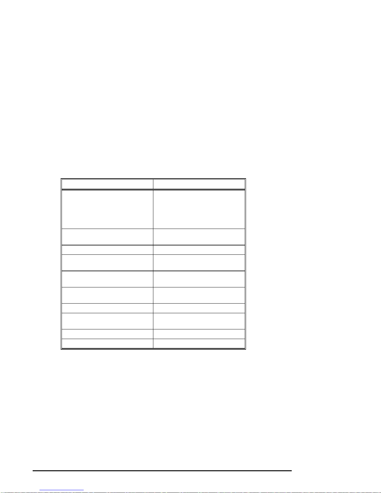
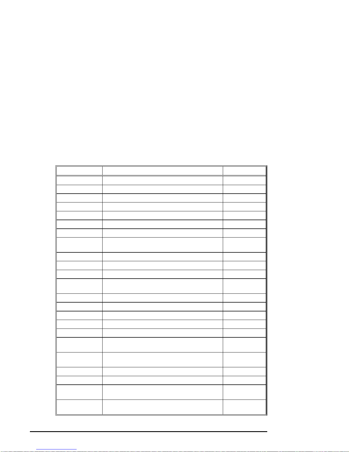
Front Panel Controls and Indicators Description
Table 1-2 describes how the front panel controls and indicators function.
Table 1-2 Front Panel Controls and Indicators
Control or Indicator Function
Halt switch Halts an OpenVMS or Digital UNIX
system, returning it to console mode
control
Does not affect a Windows NT
system.
Reset switch Reinitializes the system and performs
startup tests
On/Off switch Switches the system unit on and off
On/Off indicator Lights when the system unit is turned
on
Diskette drive activity indicator Lights when the system is accessing
the diskette drive
Diskette drive eject button Ejects a diskette from the diskette
drive
CDROM volume control Adjusts headphone volume
CDROM drive activity indicator Lights when the system is accessing
the CDROM drive
CDROM eject button Ejects disc from the CDROM drive
Operator control panel display Displays startup messages
AlphaServer 1000A Owner's Guide Overview • 1-7
Page 22
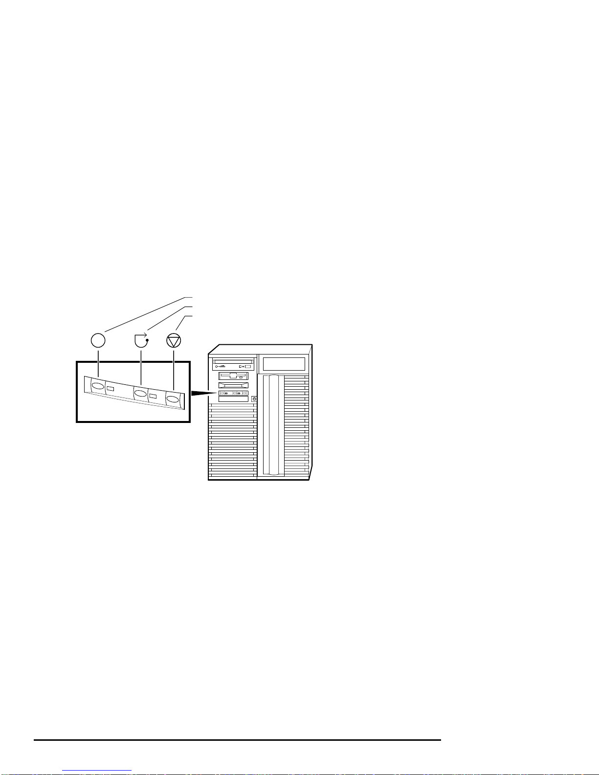
Front Panel Switches
The On/Off, reset, and halt switches are located on the left side of the front panel.
They are identified by the icons shown in Figure 1-2.
Figure 1-2 Front Panel Switches
On/Off Switch
Reset Switch
Halt Switch
MA00905
1-8 • Overview AlphaServer 1000A Owner's Guide
Page 23
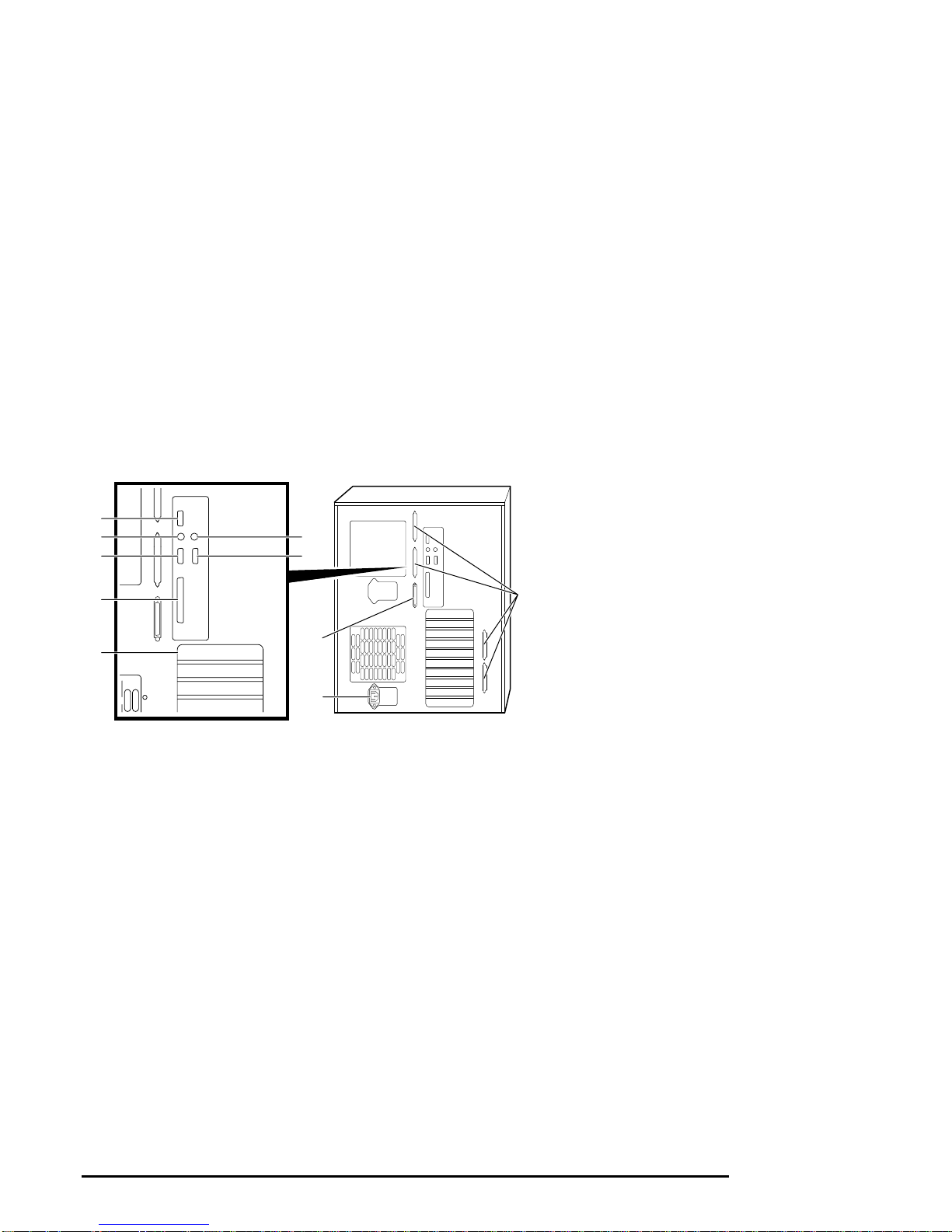
Rear Panel Ports and Slots
The ports and slots on the rear of the system unit are shown and described in Table
1-3.
Figure 1-3 Rear Panel Ports and Slots
5
4
3
2
6
7
10
8
1
9
MA00211
1 EISA/PCI slots
2 Parallel port
3 Serial port/
terminal port
(COM2)
4 Mouse port
5 VGA port
6 Keyboard port
7 Serial port/
terminal port
(COM1)
8 SCSI port (8-bit,
narrow)
9 Power inlet
10 Four additional
SCSI ports (16-
bit, wide)
AlphaServer 1000A Owner's Guide Overview • 1-9
Page 24
Rear Panel Ports and Slots Description
Table 1-3 describes the rear panel ports and slots shown in Figure 1-3.
Table 1-3 Rear Panel Ports and Slots
Port or Slot Used to connect....
Up to seven PCI slots Option cards for high-performance
network, video, or disk controllers
Up to two EISA slots Option cards for network, video,
sound, or disk controllers
Parallel port Parallel device such as a printer
Serial port/terminal port (COM1) Console terminal or serial-line
peripheral such as a modem
Mouse port PS/2-compatible mouse
VGA port VGA monitor
Keyboard port PS/2-compatible keyboard
Serial port (COM2) Serial-line peripheral such as a
modem
SCSI port External SCSI devices
Power inlet System unit to a power outlet
Four additional SCSI port knockouts External SCSI devices without using
an adjacent slot
Internal System Options
Your system supports the following types of options:
Storage options
PCI and EISA/ISA options
Memory options
Storage Options
Mass storage options are located in several compartments inside the system as shown
in Figure 1-4. The system accommodates the following types of storage options:
One diskette drive
Two removable-media storage devices, typically, a CDROM drive, a digital
audio tape (DAT) drive, or a quarter-inch cartridge (QIC) tape drive
Up to seven 3½-inch StorageWorks drives
1-10 • Overview AlphaServer 1000A Owner's Guide
Page 25
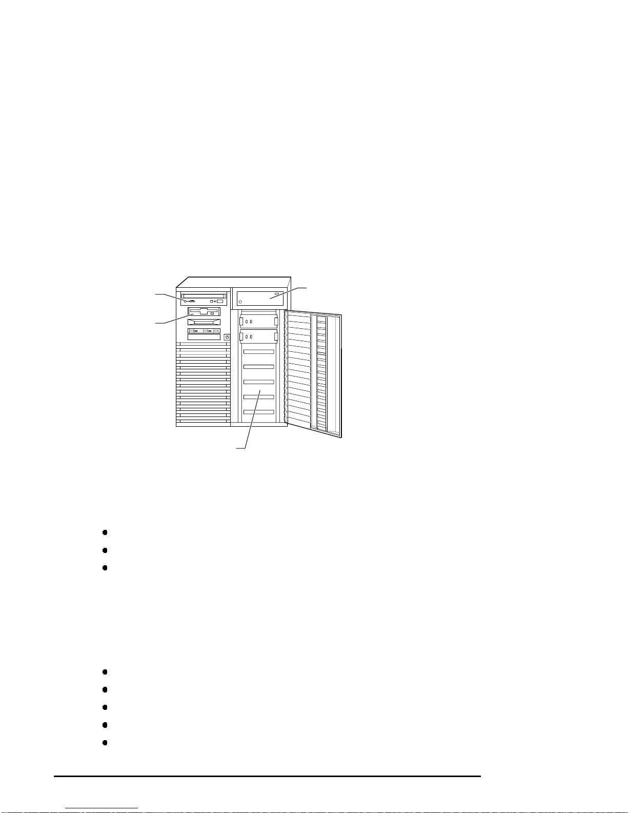
Figure 1-4 shows the locations of the storage option compartments.
Figure 1-4 Storage Option Compartments
CDROM Drive
Compartment
Diskette Drive
Compartment
StorageWorks
Drives Shelf
PCI, EISA, and ISA Options
The system supports EISA, ISA, and PCI options, including those for:
SCSI storage expansion
Networking and Communications
Graphics
Tape Drive
Compartment
MA00907
Memory Options
You can increase your system's memory to one gigabyte by using various
combinations of memory options. Adding more memory allows your system to run
memory-intensive software more quickly.
The system supports the following memory option sizes:
16 MB
32 MB
64 MB
128 MB
256 MB
AlphaServer 1000A Owner's Guide Overview • 1-11
Page 26

Memory options consist of five single in-line memory modules (SIMMs), including
one ECC module: a 16-MB option consisting of 4-MB modules, a 32-MB option
consisting of 8-MB modules, a 64-MB option consisting of 16-MB modules, a 128MB option consisting of 32-MB modules, and a 256-MB option consisting of 64-MB
modules.
External Options
External options that can be added to the system include the following:
Monitor or terminal
Expansion boxes
Printers
RAID controller
Uninterruptible power supply (UPS)
Ordering Options
The list of supported options is subject to change. Contact your sales representative
for information on the current list of supported options and for information on
ordering. If you are an Internet participant, you can obtain information related to the
AlphaServer 1000A system through the Digital FTP archive:
ftp.digital.com: /pub/DEC/Alpha/systems/as1000/docs/
For access through the Digital World-Wide Web Server:
http://www.service.digital.com/alpha/server/1000.html
Users of the Windows NT operating system can access the Microsoft hardware
compatibility list (HCL) of officially supported devices:
http://www.windowsnt.digital.com/support/hcl/hcl.htm
1-12 • Overview AlphaServer 1000A Owner's Guide
Page 27

2 Hardware Installation
Introduction
This chapter explains how to set up and install your system hardware. The following
topics are discussed:
Hardware Setup Overview
Selecting a System Location
Identifying Accessories
Connecting a Keyboard, Mouse, or Printer
Connecting a Monitor or Terminal
Connecting to Network Hardware
Verifying Hardware Setup
Locking Your System
Hardware Setup Overview
The steps for setting up your hardware are summarized as follows. Depending on
the options you use with your system, these steps may vary.
1. Select a location for the system, giving consideration to service access,
environmental conditions, and power requirements.
2. Confirm that you have all the desired accessories that ship with the system and
any additional accessories you may want to add.
3. Connect the keyboard, mouse, printer, and monitor or terminal.
4. Connect to the network hardware.
5. Verify your hardware setup.
AlphaServer 1000A Owner's Guide Hardware Installation • 2-1
Page 28
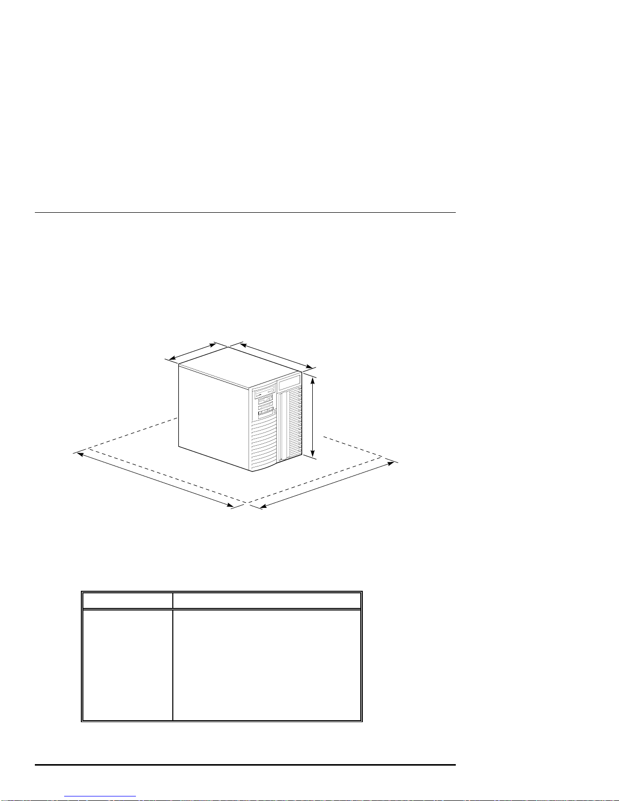
Selecting a System Location
When choosing a system location, keep in mind the optimal environmental conditions
and power requirements for the system. Be sure to keep the system in an upright
position. Figure 2-1 shows the system dimensions and the clearance needed to access
the system for servicing.
Figure 2-1 System Dimensions and Service Area
35 cm
(14.1 in)
1 m
(36 in)
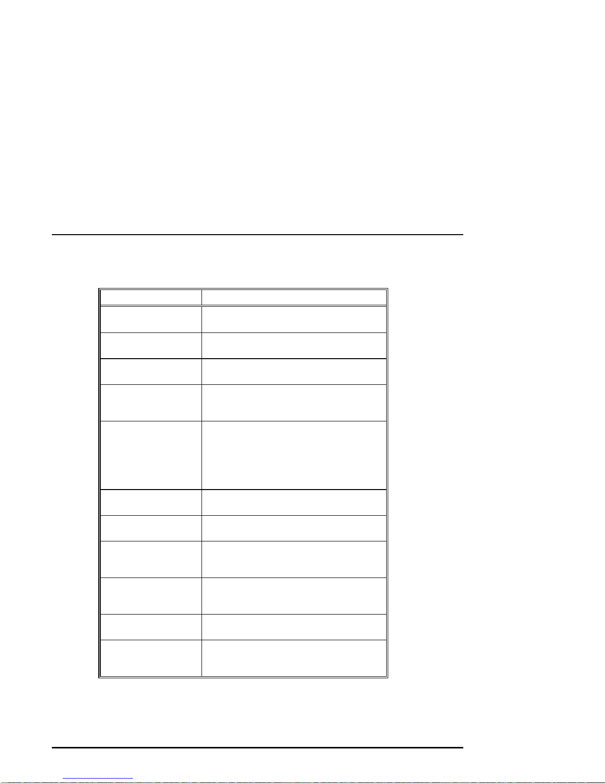
Environmental Conditions
Table 2-1 lists the environmental conditions in which the system unit best operates.
Table 2-1 Optimal Environmental Conditions
Condition Specification
Temperature range
Relative humidity
Air circulation
Room temperature: Between 10º C and 40º C
(50º F and 104º F).
Between 10% and 90% (20% to 80% with
removable media options).
Allow a minimum clearance of 8 cm (3 inches)
on all sides of the system unit to allow sufficient
air circulation. Fans inside the system unit
circulate the air to prevent excessive heat, which
can damage the system components.
53 cm
(21 in)
44 cm
(17.4 in)
65 cm
(26 in)
MA00908
2-2 • Hardware Installation AlphaServer 1000A Owner's Guide
Page 29

Power Requirements
Your system ships with one primary power supply and the option of a second power
supply. The second power supply provides redundant power to the system. Both the
primary and secondary power supplies connect to an AC outlet. An internal cable
connecting the two power supplies is required when using the second power supply.
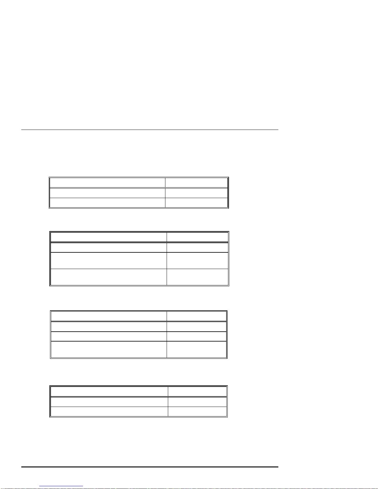
Voltage selection is not required. The system is intended for use at all rated ACinput voltages. Table 2-2 lists the power supply ratings for systems using one or two
power supplies. Figure 2-2 shows the power supply requirements for a system with
one power supply.
Table 2-2 Power Supply Ratings
Specification Range
Voltage 100-120/220-240 volts AC
Frequency 50-60 Hz
Current 8.5/4.0 amperes (one power cord)
7.5/3.5 amperes (two power cords)
Note:
These ratings are the maximum with a fully loaded system enclosure and do
not include a monitor or terminal.
Figure 2-2 Power Supply Requirements (Single Power Supply)
100-120 VAC 7.5A 50-60 Hz
220-240 VAC 3.5A 50-60 Hz
= Properly grounded power receptacle
AlphaServer 1000A Owner's Guide Hardware Installation • 2-3
Power Supply
Cable Socket
Power
Supply
Cable
MA00937
Page 30
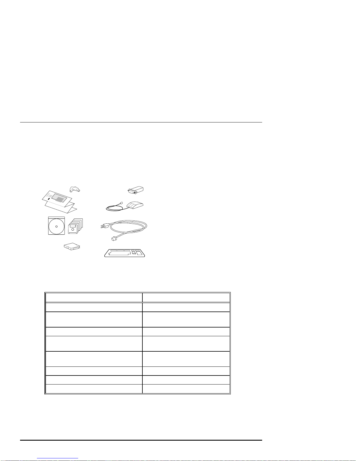
Identifying Accessories
Figure 2-3 shows the accessories that are included with the system. Table 2-2
describes the accessories.
Figure 2-3 System Accessories
1
2
3
5
6
7
4
8
MA00213
1 System unit keys (2)
2 Installation card
3 Owner's Guide (CDROM)
and EISA Configuration
Utility kit
4 External SCSI terminator
5 MMJ Serial Connector
6 Mouse
7 Power cord
8 Keyboard
Table 2-3 System Accessories
Accessory Description
System unit keys (2) Locks and unlocks the system unit
Basic Installation card and Owner's Guide
(in hardcopy and CDROM versions)
EISA Configuration Utility kit Runs the EISA Configuration Utility
External SCSI terminator Terminates the SCSI bus at system
MMJ serial port connector (H8571-1) Attaches Digital 423 DECconnect
Mouse PS/2-style mouse
Power cord Connects AC power to power supply
Keyboard PS/2-style keyboard
Installation, operation, and
troubleshooting information
rear
cables
2-4 • Hardware Installation AlphaServer 1000A Owner's Guide
Page 31

Optional Accessories
Table 2-4 lists optional accessories that you may want to order, depending on your
system's configuration.
Table 2-4 Optional Accessories
Accessory Description
Monitor or terminal VGA or SVGA monitor or terminal
Second power supply Provides redundant power in case
primary power supply fails.
Second power cord Connects AC power to second power
supply
Power supply interconnect cable (with
3-pin connector)
Connects primary and secondary
power supplies
Connecting a Keyboard, Mouse, or Printer
If you are using a keyboard, a mouse, or a printer, connect each to the appropriate
connector at the rear of the system. Refer to Figure 1-3, "Rear Panel Ports and
Slots," to verify the location of the connectors.
AlphaServer 1000A Owner's Guide Hardware Installation • 2-5
Page 32

Connecting a Monitor or Terminal
Connect a VGA monitor, an SVGA monitor, or a terminal to your system unit, as
shown in Figure 2-4.
Figure 2-4 Connecting a Monitor or Terminal
VGA
VTxxx
Terminal Port
(COM1)Connection
Connecting to Network Hardware
Mouse Port
Connection
Keyboard Port
Connection
High-Performance
Graphics Option
Card Slot
MA00947
Your system supports various network options. You can connect to ThinWire, AUI,
or 10Base-T Ethernet networks as shown in Figure 2-5. With appropriate options,
you can also connect to FDDI and token ring networks.
2-6 • Hardware Installation AlphaServer 1000A Owner's Guide
Page 33

Figure 2-5 Network Connections
Verifying Hardware Setup
Before turning on the system, check that you have made all the proper cabling
connections, as shown in Figure 2-6. Refer to the section, "Basic Operation," for
information about turning on your system.
10BASE-T Cable
AUI Cable
ThinWire Cable
MA00938
Figure 2-6 External System Cabling
Terminal
VTxxx
Printer
AlphaServer 1000A Owner's Guide Hardware Installation • 2-7
Modem
Power Cable
VGA Monitor
VGA
High-Performance
Graphics Option
Mouse
Keyboard
MA00939
Page 34

Locking Your System
The system unit is protected by a key lock located on the front door that prevents
unauthorized access to the hardware inside the unit. Turning the key to the left locks
the front door. When the front door is locked, the top cover and side panels cannot
be removed. Turning the key to the right unlocks the system unit and allows you
access to install or remove system components. When the system unit is unlocked,
push the lock to open the door. Figure 2-7 shows the system lock in the unlocked
position.
To remove the top cover, pull down the latch located on the front of the system above
the lock, and while holding down the latch, pull the top cover off from the rear of the
system. With the top cover and side panels removed, the system cannot be turned on.
Figure 2-7 System Lock and Key
2-8 • Hardware Installation AlphaServer 1000A Owner's Guide
MA00909
Page 35

Additional security is provided by a latching loop on the rear panel of the system unit
that allows you to attach the system unit to a post or other fixed object.
Recording the System Unit Key Number
Write down the number and letter of the system unit key and record this information
in a safe place in case you need to order a replacement key. Figure 2-8 shows the
location of the key number on the system unit key.
Figure 2-8 System Unit Key Number Location
Key Number
Location
00
MA00948
AlphaServer 1000A Owner's Guide Hardware Installation • 2-9
Page 36

Page 37

3 Preparing to Install an Operating
System
Introduction
This chapter covers the following topics:
• Preparing to Install Windows NT
• Preparing to Install Digital UNIX
• Preparing to Install OpenVMS Alpha
These sections explain how to prepare for installing or upgrading:
Windows NT Server or Workstation 3.51 or later
Digital UNIX Version 3.0B or later
OpenVMS Alpha Version 6.2-1H2 or later
Note: If your system was shipped with pre-installed
software, proceed to "Booting the Operating System"
in Chapter 4 "Basic Operation," and refer to the
software documentation to start up your operating
system for the first time.
Preparing to Install Windows NT
Preparing the System
1. Before you install the Windows NT operating system, make sure that you have
the following items:
AlphaServer 1000A Owner's Guide Preparing to Install Operating System • 3-1
Page 38

Microsoft Windows NT ARC firmware for the AlphaServer 1000A, Version
4.44 or later. The ARC firmware is a menu-driven utility to configure your
system, and Version 4.44 is required to run Windows NT 3.51 or later.
Microsoft Windows NT Server or Workstation 3.51 or later.
The EISA Configuration Utility (ECU) diskette for Microsoft Windows NT,
Version 1.8 or later.
A partitioned and formatted hard disk drive installed in your system. If your
drive has not yet been prepared, follow the instructions in "Hard Disk
Preparation" later in this section.
2. If a Microsoft Windows NT product announcement was included with your
system, read the announcement, which contains important READ FIRST
information.
3. Contact the administrator of your local area network to obtain the network
information you will need. This information will vary depending on the type of
network hardware and software installed at your location.
Setting the Operating System Type
1. Turn the system on by pressing the On/Off switch on the front of the system.
(See Chapter 4, "Basic Operation.") After a short wait, the operator control
panel on the front of the system displays the message "Model 4/2xx," and the
screen displays initialization and testing information. Internal errors are
indicated by audible "beep" codes. (See Chapter 8, "Troubleshooting.")
2. Press the Enter key. If your screen displays the ARC console Boot menu, your
system has already been prepared for use with Microsoft Windows NT and you
can proceed to the next section, "Updating the Firmware."
If your screen displays a triple arrow (>>>) prompt instead of the ARC console
Boot menu, your system has booted the SRM console. Proceed to step 3.
3. Type the following two commands at the SRM console prompt and press the
Enter key after each command:
set console graphics
set os_type nt
4. Turn off the power to your system by pressing the On/Off switch on the front of
your system. Wait at least 10 seconds, then turn the power back on.
5. The system performs several diagnostics. If you see an ECU error message, you
can ignore it, because the remainder of the configuration procedure will correct
any configuration errors that are displayed on the screen.
3-2 • Preparing to Install Operating System AlphaServer 1000A Owner's Guide
Page 39

Updating the Firmware
When the ARC Boot menu is displayed, note the firmware version number at the top
of the screen display. Compare this version number to the required version listed in
your Windows NT documentation. If no update is required, proceed to the section,
"Setting Default Environment Variables." If an update is required, follow these
steps:
1. From the Boot menu, use the arrow keys to highlight the Supplementary menu,
then press the Enter key.
2. Insert the Digital AlphaServer 1000A Drivers and Firmware Update diskette or
CDROM
for Windows NT 3.51 into the drive.
3. From the Supplementary menu, select "Install new firmware" and press the Enter
key. The update process begins and the following prompt appears.
Apu ->
4. Type Update and press the Enter key.
5. At the prompt, "Are you ready to program device?" type the letter y and press the
Enter key.
6. If the update is successful, the screen displays the message, "ARC ROM update
successful." If this message is not displayed, call your technical support
representative for further assistance.
7. Turn off the power to your system by pressing the On/Off switch on the front of
your system. Wait at least 10 seconds, then turn the power back on.
Note: For more information on updating firmware,
see "Upgrade Options" in Chapter 7, "Upgrading."
Setting Default Environment Variables
After updating the firmware, verify that the correct firmware version number is
displayed at the top of the ARC Boot menu. Then follow these steps to set the
default environment variables:
1. From the ARC Boot menu, select the Supplementary menu and press the Enter
key.
2. Select "Set up the System..." and press the Enter key.
3. Select "Set default environment variables" and press the Enter key.
4. When prompted to enter the system partition location, select "SCSI hard disk"
and press the Enter key.
AlphaServer 1000A Owner's Guide Preparing to Install Operating System • 3-3
Page 40

5. When prompted to enter SCSI bus and SCSI ID numbers, enter the SCSI bus
and ID for the location for the system partition. These values are used to set an
environment variable, which Windows NT uses to determine the correct drive
and partition to boot from.
If you are unsure about these values, simply accept the default values of 0. If
these values are incorrect for your particular system (if, for example, your hard
drives are on a secondary controller on SCSI bus 1), NT setup will prompt you
to run the arcinst utility. The arcinst utility provides valid values to choose for
setting this environment variable correctly.
6. When prompted to enter the partition number on the disk, verify that it is set to 1,
and press the Enter key. If you plan to partition your hard disk, set the partition
number to 2. Otherwise, enter the boot partition number corresponding to your
existing disk and NT configuration.
If you are unsure about your disk configuration, select "Display hardware
configuration" to view a summary of your system hardware.
7. Select "Set default configuration" and choose the diskette and keyboard settings
that correspond to your system.
Setting the EISA Configuration
1. Insert the EISA Configuration Utility (ECU) diskette for Microsoft Windows NT
into the diskette drive on your server.
2. From the Setup menu, select "Run EISA Configuration Utility from floppy" and
press the Enter key. After a few moments, the EISA Configuration Utility dialog
box appears. Press the Enter key.
If any of the EISA option cards in your computer have not yet been identified, a
Caution dialog box is displayed. You can ignore this dialog box because your
option cards will be identified in the following steps.
3. Press the Enter key to display the "Steps in Configuring your Computer" dialog
box.
4. Select "Step 3: View or edit details" to verify your system's configuration
(optional).
Note: Your system supports two EISA option slots.
Your ECU display may show more than two slots, but
only the first two are valid.
5. Select "Step 5: Save and Exit" and press the Enter key. At the confirmation
prompt, select "Save the configuration" and press the Enter key. When a dialog
3-4 • Preparing to Install Operating System AlphaServer 1000A Owner's Guide
Page 41

box appears, indicating that the configuration has been saved, press the Enter
key. Your system will restart with the updated information.
Preparing Your Hard Disk
If your first hard disk is already partitioned and formatted with either the FAT or
NTFS file systems, you can omit the steps in the section "Partitioning and Formatting
the First Hard Disk" and begin installation of the Microsoft Windows NT software.
It is recommended that you partition and format your system's hard disk before
installing Windows NT software, even if your hard disk has already been partitioned
and formatted. Repartitioning and reformatting reduce the likelihood of operational
problems due to conflicting versions of the operating system or disk-related
problems.
Note: If the first hard disk in your system currently
contains any information that you need, back that
information up to another medium before proceeding.
Partitioning and Formatting Your Hard Disk
Note: Omit these steps if you want to maintain your
current partitions.
1. Insert the Microsoft Windows NT CDROM into your system's CDROM drive.
2. Turn on your system. After your system performs startup diagnostics, the screen
displays the Windows NT (ARC) console Boot menu.
3. From the Boot menu, select "Run a program" and press the Enter key. A
"Program to run" prompt appears.
4. Type cd: \alpha\arcinst and press the Enter key. The ARC Installation Program
screen is displayed.
5. Select "Configure Partitions" and press the Enter key. The available disk
partitioning options appear.
6. Select "Delete Partition" and press the Enter key. If your system has only one
hard disk, press the Enter key. If your system has more than one hard disk,
select the disk to be prepared, and press the Enter key.
Depending on the previous disk configuration, you might be notified that no
partitions exist, or you may see a list of one or more partitions. Follow the onscreen prompts to delete all partitions on the disk.
AlphaServer 1000A Owner's Guide Preparing to Install Operating System • 3-5
Page 42

7. Select "Create Partition" and press the Enter key. When the list of available
disks appears, select the disk to be prepared and press the Enter key. You are
prompted for the size of the partition.
8. Type 6 after the "Enter size" prompt, then press the Enter key. A 6-megabyte
partition is created. This partition will be a file allocation table (FAT) system
partition. Note that the number you enter depends on the maximum partition
size. The number must equal the maximum size displayed minus 6. For
example, if the largest possible value is 500, you would enter 494.
9. Press the Enter key to format the partition. Once the formatting is completed,
press the Enter key again.
10. Select "Create Partition" and press the Enter key. When the list of available
disks appears, select the first disk again and press the Enter key. You are
prompted for the size of the partition.
11. Type the larger of the two values at the "Enter size" prompt, then press the Enter
key. The partition is created.
12. Press the Enter key to format the partition. Once the formatting is completed,
press the Enter key again.
13. Select "Make Existing Partition into a System Partition" and press the Enter key.
A message may appear asking whether to overwrite an already defined system
partition. Type y.
If the message, "Boot selections already exist" is displayed, exit the ARCINST
program, go to the Setup menu, choose "Manage boot selections," and delete all
existing boot selections. Then return to the Boot menu to restart the ARCINST
program and return to step 13 in these instructions.
14. When the list of available disks is displayed, select the same disk you just
formatted and then press the Enter key. The list of available partitions is
displayed.
15. Select "Partition 1" and press the Enter key. Your system is now prepared for
installation of Microsoft Windows NT.
16. Select Exit and press the Enter key. Select Exit again and press the Enter key.
Installing Microsoft Windows NT
From the ARC Boot menu, select the Supplementary menu and press the Enter key.
When the Supplementary menu appears, select "Install Windows NT from CDROM"
3-6 • Preparing to Install Operating System AlphaServer 1000A Owner's Guide
Page 43

and press the Enter key. At this point, installation of Windows NT begins. For
further installation information, refer to your Windows NT documentation.
Note: During installation, you are prompted for the
location of the files for Microsoft Windows NT. Install
the files into the larger of the two partitions you just
created, and when prompted, format that partition with
the NTFS file system.
Preparing to Install Digital UNIX
Installation Preparation
Before installing Digital UNIX (DEC OSF/1) on your system, make sure that you
have the following items:
• Digital UNIX Version 3.0B, Version 3.2d, or later
• SRM console firmware, Version 2.0-3 or later
• EISA Configuration Utility (ECU) diskette, Version 1.8 or later, for Digital
UNIX and OpenVMS Alpha.
Before starting installation, be sure to review the Digital UNIX release notes
("General Installation") and the Digital UNIX installation guide for your version of
the operating system.
Setting the Operating System Type
1. Turn the system on. After a short wait, the operator control panel on the front of
the system displays the message "Model 4/2xx," and the screen displays
initialization and testing information.
2. Press the Enter key. If the screen displays a triple arrow prompt (>>>) you have
booted the SRM console. Verify the value of the
environment variable. It should be set to "new." (See "Booting the Operating
System" in Chapter 4, "Basic Operation.") Then, proceed to the next section,
"Installing Digital UNIX."
If the computer booted directly into the ARC Boot menu, and you did not see the
>>> prompt, you must proceed to step 3 to switch to the SRM console.
3. From the ARC Boot menu, select the Supplementary menu.
4. From the Supplementary menu, select "Set up the system."
AlphaServer 1000A Owner's Guide Preparing to Install Operating System • 3-7
set bus_probe_algorithm
Page 44

5. From the Setup menu, select "Switch to OpenVMS or Digital UNIX console."
This allows you to select your operating system console.
6. Select your operating system, then select "Enter" on the Setup menu.
7. When the system displays the message, "Power-cycle the system to implement
the change," press the Reset button.
These steps initiate loading of the firmware. Once the Digital UNIX and
OpenVMS Alpha firmware is loaded and the system is initialized, the system
displays the SRM console prompt (>>>).
8. Verify the value of the
set bus_probe_algorithm
should be set to "new." (See "Booting the Operating System" in Chapter 4,
"Basic Operation.")
Installing Digital UNIX
To install the Digital UNIX operating system from a CDROM or to do a remote
installation over a local network using Remote Installation Service (RIS), refer to
your operating system documentation.
Preparing to Install OpenVMS Alpha
Preparing the System
Before you install the OpenVMS Alpha operating system on your system, make sure
that you have the following:
• OpenVMS Alpha operating system, Version 6.2-1H2 or later
• SRM console firmware, Version 2.0-3 or later
• EISA Configuration Utility (ECU) diskette for Digital UNIX (DEC OSF/1)
and OpenVMS Alpha, Version 1.8.
Before beginning the installation or upgrade, prepare the required hardware and
software components, as described in this section. After preparation is complete,
refer to the OpenVMS Alpha Version 6.2 Upgrade and Installation Manual to install
the operating system.
environment variable. It
Preparing Hardware Components
To prepare the hardware components, follow these steps:
1. Be sure the hardware has been installed and checked for proper operation.
3-8 • Preparing to Install Operating System AlphaServer 1000A Owner's Guide
Page 45

2. Be sure you know how to turn on and operate your system components, including
the system unit, console, monitor or terminal, drives, and printer. Refer to the
section, "Basic Operation" in this guide, if necessary.
3. Set up your system to record the installation procedure on either a hardcopy
terminal or a printer attached to the console terminal. If you do not do this, the
screen messages will be lost. You may want to record a transcript of screen
messages to refer to during installation.
Preparing Software Components
To prepare the software components, follow these steps:
1. Be sure you have all the items listed on the bill of materials in the software
distribution kit. If your distribution kit is incomplete, notify your service
representative and request priority shipment of any missing items.
2. Review all cover letters and release notes.
Setting the Operating System Type
To set the operating system type, follow steps 1 through 7.
1. Turn the system on. After a short wait, the operator control panel on the front of
the system displays the message "Model 4/2xx" and the screen displays
initialization and testing information.
2. Press the Enter key. If the screen displays a triple arrow prompt (>>>), you
have booted the SRM console. Verify that the
environment variable is set to "new." (See "Booting the Operating System" in
Chapter 4, "Basic Operation.") Then, proceed to the section "Installing
OpenVMS Alpha".
bus_probe_algorithm
If the computer booted directly into the ARC Boot menu, and you did not see the
>>> prompt, you must proceed to step 3 to switch to the SRM console.
3. From the ARC Boot menu, select the Supplementary menu.
4. From the Supplementary menu, select "Set up the system."
5. From the Setup menu, select "Switch to OpenVMS or Digital UNIX console."
This allows you to select your operating system console.
6. Select your operating system, then select Enter on the Setup menu.
7. When the system displays the message, "Power-cycle the system to implement
the change," press the Reset button.
AlphaServer 1000A Owner's Guide Preparing to Install Operating System • 3-9
Page 46

These steps initiate loading of the firmware. Once the Digital UNIX and
OpenVMS Alpha firmware is loaded and the system is initialized, the system
displays the SRM console prompt (>>>).
8. Verify the value of the
should be set to "new." (See "Booting the Operating System" in Chapter 4,
"Basic Operation.")
Required PALcode
If your computer console does not have a specific minimum version of the privileged
architecture library code (PALcode), you may not be able to boot your system during
the installation or upgrade procedure. To ensure the correct version, follow these
steps before performing an installation or upgrade:
1. At the SRM console prompt (>>>) on your running system, enter the show
configuration command. The system display will indicate the PALcode
version your system is using.
2. To determine whether your system is running the required or recommended
version of PALcode, refer to the most recent OpenVMS Alpha operating system
cover letter or release notes to check for new information that supplements the
PALcode information in the OpenVMS Alpha Version 6.2 Upgrade and
Installation Manual. You can also contact your service representative.
3. If the PALcode version is below the required or recommended minimum, upgrade
your firmware either by following the directions in the section, "Firmware," in
Upgrading, or by contacting your service representative.
set bus_probe_algorithm
environment variable. It
Installing OpenVMS Alpha
Use the OpenVMS Alpha CDROM to install or upgrade the operating system, or to
perform operations such as backing up the system disk. For installation information,
refer to your operating system documentation.
3-10 • Preparing to Install Operating System AlphaServer 1000A Owner's Guide
Page 47

4 Basic Operation
Introduction
This chapter explains how to start and stop your system, issue console commands,
and operate other basic system functions. It includes the following topics:
Turning the System On
Turning the System Off
Accessing the System from a Remote Location
Interpreting Startup Messages
Using the Consoles
Booting the Operating System
Using Storage Drives
Caring for Your System
This chapter assumes that you have set up the hardware and made all necessary
connections, as described in the Hardware Installation chapter.
Turning the System On
Note: Your server may be equipped with pre-installed
operating system software when you receive it.
To turn on a system that has pre-installed operating system software, follow steps 1
through 5 below. For a system without pre-installed software, follow steps 1 through
8:
1. Connect any external options, such as monitors or terminals, or expansion boxes
that house storage devices.
2. Make sure the top cover and side panels of the system unit enclosure are in place.
The system will not start if the cover and side panels are not in place.
AlphaServer 1000A Owner's Guide Basic Operation • 4-1
Page 48

3. Plug the power cord into a wall outlet. If your system has two power supplies,
plug in a power cord for each one.
4. Turn on any external options that are connected to the system.
5. Press the On/Off switch on the front of the system unit. The switch stays
depressed in the "on" position. The green On/Off indicator on the front of the
system will light.
Figure 4-1 shows the location of the On/Off switch (1 shows the switch in the
"on" position; 2 shows the switch in the "off" position).
Figure 4-1 Location of the On/Off Switch
On/Off Switch In
("On" Position)
On/Off Switch Out
("Off" Position)
The screen on your monitor or terminal will display test codes and initialization
messages. When the startup procedure is complete, the operator control panel
displays the message "Model 4/2xx." The screen displays the SRM console
prompt (>>>) or the ARC menu, depending on how the
variable has been set.
6. If you encounter a problem, verify that you correctly followed steps 1 through 5.
Refer to Chapter 8, "Troubleshooting" for more information. If your operating
system was preinstalled, proceed to the section, "Turning the System Off."
7. At this point, if your operating system was not preinstalled, you may have to
perform one or all of the following tasks, depending on the startup display
messages and the operating system you choose to run. Refer to the section
"Booting the Operating System" in this chapter for more information on each of
these tasks.
4-2 • Basic Operation AlphaServer 1000A Owner's Guide
MA00910
os_type
environment
Page 49

Run the EISA Configuration Utility.
Check required environment variable settings.
Change the way your system powers up or boots.
Verify your configuration.
8. Install the operating system. (Refer first to Chapter 3, "Preparing to Install an
Operating System" and then refer to your operating system documentation.)
9. Reboot the system by pressing the Reset button.
10. If you encounter a problem, verify that you correctly followed steps 1 through 8.
Refer to Chapter 8, "Troubleshooting" for more information.
Turning the System Off
You may not need to turn the system off in order to resolve system hangs or similar
problems. You can often recover from hangs or other problems by pressing the Reset
switch on the operator control panel shown in Figure 1-2.
Caution: Pressing the Reset switch
reinitializes the system and causes you to lose
the applications you are running.
Within Windows NT, pressing the Ctrl, Alt,
and Delete keys at once allows you to shut
down the operating system and bring up the
ARC firmware with no loss of data.
The following list summarizes the steps for turning the system off.
1. Shut down the operating system, following the instructions in the operating
system documentation.
2. Press the On/Off switch on the front of the system unit.
Turning the System Off for an Extended Period
If you need to turn off your system for an extended period, first turn off power as
described above. Next, unplug the power cords from the power outlets.
Caution: If two power supplies are present,
unplug the power cord for each supply.
AlphaServer 1000A Owner's Guide Basic Operation • 4-3
Page 50

Accessing the System from a Remote Location
If you are running the Digital UNIX or OpenVMS Alpha operating systems, you can
invoke console mode from a remote device that is connected to your system through
one of the serial ports on the rear of the system. The default console port is COM1.
(See Figure 1-3, which shows the rear panel ports and slots.)
To access the system from a remote location, follow these steps:
1. If you are running Digital UNIX or OpenVMS Alpha, shut down the operating
system (refer to the operating system documentation, if necessary). When the
shutdown has completed, press Return.
The SRM console prompt (>>>) is displayed. Set the console to serial mode by
turning the system off and then on or by using the following commands at the
console prompt:
>>> set console serial
>>> init
Note: From a remote location, you cannot reset or
initialize a system running Windows NT. If the
system is running Windows NT when you try to
access it from a remote location, attempts to access
the system will fail.
2. Connect to your system from the remote location.
Note: Setting the
variable to 1 enables login to the SRM console
firmware from alternative console ports. Setting it to
0 disables.
If you want to run the EISA Configuration Utility (ECU) from a terminal
connected to a serial line, refer to the section, "EISA Configuration Utility
(ECU)" in Chapter 6 for more information.
Note: The terminal must be set for 8-bit controls, the
keyboard set so that the tilde (~) key sends the escape
signal, and the console environment variable set to
serial.
4-4 • Basic Operation AlphaServer 1000A Owner's Guide
tt_allow_login
environment
Page 51

Interpreting Startup Messages
After you turn the system on, the operator control panel and your monitor or terminal
screen provide the following status information:
The countdown and ready message on the operator control panel
The system startup display on your monitor or terminal screen
The Boot menu (for Windows NT systems) or the console prompt (for Digital
UNIX or OpenVMS Alpha systems) on your monitor or terminal screen
Audible beep codes indicate startup errors. See "Interpreting Error Beep Codes" in
Chapter 8, "Troubleshooting."
While the system runs the startup tests, the operator control panel on the front of the
system displays a series of codes. When the startup tests are complete, the operator
control panel displays the following message:
Model 4/2xx
During the startup sequence, the startup display scrolls on your monitor or terminal
screen. The Windows NT system startup display looks similar to Example 4-1.
After the startup display, the operating system determines whether your system
displays a Boot menu (for the Windows NT operating system) or a console prompt
(for Digital UNIX and OpenVMS Alpha operating systems). If the system does not
display either a menu or a console prompt, press the Return key several times. If
there is no response, refer to the "Troubleshooting" section of this guide for more
information.
Systems with Windows NT
If you are using the Windows NT operating system, the ARC firmware displays the
Windows NT Boot menu after the system startup display. The following example
shows the Windows NT Boot menu.
Example 4-1: Windows NT Boot Menu
Alpha Firmware Version n.nn
Copyright (c) 1993-1995 Microsoft Corporation
Copyright (c) 1993-1995 Digital Equipment Corporation
Boot menu:
Boot the Windows NT operating system
Boot an alternate operating system
Run a program
AlphaServer 1000A Owner's Guide Basic Operation • 4-5
Page 52

Supplementary menu...
Use the arrow keys to select, then press Enter.
Systems with Digital UNIX or OpenVMS Alpha
If you are using the Digital UNIX or OpenVMS Alpha operating systems, the SRM
console prompt is displayed after the system startup display. The prompt looks like
this:
>>>
To display any messages that may have scrolled by, enter the
more el
command at the console prompt. Either command lists the contents of the
event log file one screen at a time.
The following example shows a sample startup display and the SRM console prompt
for systems running Digital UNIX or OpenVMS. (The initial lines, related to
copyright and patent information, remain on-screen for a few seconds only.)
Example 4-2: Digital UNIX or OpenVMS Alpha SRM Startup Display
BIOS Emulation V1.15a
Copyright (c) 1993-1995 Digital Equipment Corporation
All Rights Reserved
Patent Pending
cat el
command or
initializing keyboard
eb.....ea.e9.e8.e7.e6.e5.e4.e3.e2.e1.e0.
Xn.n-nnnn, built on Oct 4 1996 at 14:48:51
>>>
Reading the Startup Test Results
The Windows NT startup test display looks similar to the following example. Test
failures are indicated by an error list including errors that must be fixed before
Windows NT may be booted.
BIOS Emulation V1.15a
Copyright (c) 1993-1995 Digital Equipment Corporation
All Rights Reserved
Patent Pending
4-6 • Basic Operation AlphaServer 1000A Owner's Guide
Page 53

Initializing firmware
Initializing EISA bus 0
Initializing device drivers: NCRC810, SWXCR, QLOGIC, KZPSA...OK
The Digital UNIX and OpenVMS Alpha startup test displays indicate successful
tests with the word OK.
If the System Passes Startup Tests
If the system passes the startup tests, it either boots the selected operating system or
emits audible "beep" codes and halts in console mode, depending on the system
default settings.
If the System Fails Startup Tests
The following list summarizes the steps to follow if the system fails the startup tests.
1. Turn the system unit off, wait approximately 15 seconds, then turn it on again.
2. If the system continues to fail the startup tests, or emits audible error beep codes
and halts, refer to the "Troubleshooting" section of this guide.
Using the Consoles
The Windows NT (ARC) console and the Digital UNIX and OpenVMS Alpha
(SRM) console are used to perform different tasks. For example, ROM-based
diagnostics (such as the
test
OpenVMS Alpha console, regardless of the operating system you are running.
Invoking Console Mode
To perform tasks from console mode you must first invoke console mode by shutting
down the operating system according to the operating system shutdown procedure
described in your operating system documentation. If you are running either the
Digital UNIX or OpenVMS Alpha operating system, you can also invoke console
mode by pressing the Halt switch on the operator control panel.
AlphaServer 1000A Owner's Guide Basic Operation • 4-7
command) are run only from the Digital UNIX and
Page 54

Caution: If you are running Digital UNIX or
OpenVMS Alpha operating systems, press the
Halt switch only after you have shut down the
operating system using the proper shutdown
procedure.
The Halt switch does not affect the Windows NT operating system. To invoke
console mode in Windows NT, shut down the operating system following the
procedure described in the operating system documentation. Turn the system off and
then on or press the Reset switch.
When to Switch Consoles
You can perform most console-related tasks from the interface designed to interact
with your operating system. However, the console interfaces are designed so that
you can easily switch between them. You will need to switch between the consoles in
the following instances:
If you are running Digital UNIX or OpenVMS Alpha and need to run the RAID
Configuration Utility (RCU) or other adapter utilities such as those for the
KZPSA or Qlogic options, switch to the Windows NT (ARC) console.
If you are running Windows NT and want to perform any of the following tasks,
switch to the Digital UNIX and OpenVMS Alpha (SRM) console:
1. Test the system (other than self-tests at system startup)
2. Examine and verify memory locations that are recognized by the system
3. Set or change some environment variables, such as Ethernet device type and
speed for Fast SCSI devices
4. Verify the versions of all firmware PALcode.
Switching to the Digital UNIX and OpenVMS Alpha (SRM) Console
Depending on the command you used to invoke the Windows NT (ARC) console,
you may be able to switch to the Digital UNIX and OpenVMS Alpha (SRM) console
by pressing the Reset switch on your system unit, or turning the system off and then
back on. If you typed >>> arc or >>>runecu at the SRM console prompt,
you can use this method.
However, if you typed >>> set os_type nt, use the following procedure,
which loads the firmware:
1. From the ARC Boot menu, select the Supplementary menu.
4-8 • Basic Operation AlphaServer 1000A Owner's Guide
Page 55

2. From the Supplementary menu, select "Set up the system."
3. From the Setup menu, select "Switch to OpenVMS or Digital UNIX console" to
select your operating system console.
4. Press enter on the Setup menu.
5. When the system displays the message, "Power-cycle the system to implement
the change," press the Reset button.
Once the Digital UNIX and OpenVMS Alpha firmware is loaded and the system is
initialized, the system displays the SRM console prompt (>>>).
Switching to the Windows NT (ARC) Console
To switch from the Digital UNIX or OpenVMS Alpha (SRM) console to the
Windows NT (ARC) console, type the following command at the console prompt:
>>> set os_type nt
AlphaServer 1000A Owner's Guide Basic Operation • 4-9
Page 56

Then turn the system off and then back on. This procedure loads the firmware. Once
the Windows NT firmware is loaded and the system is initialized, the system displays
the Windows NT Boot menu.
Note: If the screen display shows option device names
flashing, see "Troubleshooting," later in this guide.
As an alternate method, you can use the following command to switch from the SRM
to the ARC console in your current session but return to the SRM console if you turn
off the system:
>>> arc
Windows NT (ARC) Console Menus
The Windows NT (ARC) console has three primary menus: the Boot menu, the
Supplementary menu, and the Setup menu.
Boot Menu Functions
The Boot menu contains menu items that allow you to perform the following tasks:
Boot the default boot selection
Boot an alternative boot selection
Run a program
Access the Supplementary menu
Supplementary Menu Functions
The Supplementary menu contains items that allow you to perform the following
tasks:
Install new firmware
Install Windows NT from a compact disc
Access the Setup menu
List the ARC firmware device names for the installed devices
Return to the Boot menu
4-10 • Basic Operation AlphaServer 1000A Owner's Guide
Page 57

Setup Menu Functions
The Setup menu contains menu items that allow you to perform the following tasks:
Set the system time
Set the default system partition
Configure the system floppy drives and keyboard
Manage the Windows NT (ARC) boot selections
Set the system to boot automatically
Run the EISA Configuration Utility
Edit the system environment variables
Reset the system to factory defaults
Set the default operating system and system firmware
Return to the Supplementary menu, with or without saving Setup menu changes
Digital UNIX and OpenVMS Alpha (SRM) Console Commands
There are two levels of Digital UNIX and OpenVMS Alpha (SRM) console
commands:
Basic
Comprehensive
Basic Commands
Use basic commands to perform common tasks described in this guide. Table 4-1
lists each console task and provides the corresponding command and its syntax.
Note: To limit the screen display to 23 lines at a time, use:
>>> more [filename]
>>> [command] | more
AlphaServer 1000A Owner's Guide Basic Operation • 4-11
Example:
.
Example:
>>> more el
>>> show config | more
Or, use
.
Page 58

Table 4-1 Basic SRM Console Commands
Task Command Syntax
Boot the Windows NT
(ARC) console
firmware.
Boot the operating
system.
Display error logs.
Resume program
execution.
Invoke the EISA
Configuration Utility.
Display online help on
using console
commands.
Initialize the system.
Halt system tests
invoked by test
command.
Display online help on
using console
commands.
Display status of all
system processes.
Set an environment
variable.
Display the value of an
environment variable or
display configuration
information.
Test the system and
display results.
arc arc
boot boot [-flags
cat el
continue continue
ecu ecu
help help [
init init
kill_diags kill_diags
man man [
ps ps
set set [-default]
[
longword,]longword
[-halt] [[
boot_device
cat el or more el
val
show show [
test test
[{config,device,memory,
pal,version}]
filename
command
command
envar
]
]
. . .]
. . . ]
envar
]
Caution:
exactly as shown, not abbreviated. The system will
not recognize an abbreviated form.
4-12 • Basic Operation AlphaServer 1000A Owner's Guide
Environment variables must be entered
Page 59

Comprehensive Commands
Additional commands are available for system diagnosis and other complex tasks.
Use of these commands requires detailed knowledge of your system. Do not use
these commands without fully understanding the effect they can have on your system.
To see a list of additional commands, enter help or man at the SRM console
prompt.
SRM Console Security Features
Console security features, which restrict access to certain console commands, are
intended to prevent unauthorized users from modifying system parameters or
otherwise tampering with the system from the console. The SRM console supports
two modes:
Secure mode allows access only to specific console commands: start,
continue, boot (with stored parameters), and login.
User mode allows access to all SRM console commands
Note: The security features work only if
access to the system hardware is controlled.
Be sure to keep the front panel of the system
locked and the key secure.
The set secure Command
Use the set secure command to enable the security features without restarting
the console. If the console password has already been set, access will be limited to
the start, continue, boot (using the stored parameters), and login
commands. For example:
>>> set secure
Console is secure
If the password has not been set, the console will prompt you to set it. (See "The set
password Command.")
>>> set secure
Secure not set. Please set the password.
The set password Command
Use the set password command to set or change the console password. If the
password has already been set, the console prompts you for the new password and
verification, then for the old password.
AlphaServer 1000A Owner's Guide Basic Operation • 4-13
Page 60

>>> set password
Please enter the password:
Please enter the password again:
Now enter the old password:
>>>
If the validation password does not match the one previously set, the password does
not change.
>>> set password
Please enter the password:
Please enter the password again:
Validation error
If the password has not been set, the console prompts you for the new password and
verification.
>>> set password
Please enter the password:
Please enter the password again:
>>>
The login Command
Use the login command to turn off the security features and gain access to all the
SRM console commands during a particular session. If a password has not been set
when you enter the login command, you will be prompted to set it, but you need
not do so unless you wish to.
>>> login
Secure not set. Please set the password:
>>>
When the console prompt is redisplayed, the console is no longer in secure mode. If
a password has been set when you enter the login command, you must enter the
password at the prompt:
>>> login
Please enter the password:
If the password you enter matches the current password, the secure mode is turned
off and all console commands can be used. You can then return to secure mode by
initializing the system or entering the boot, continue, or start command.
Note: The password length must be between
15 and 30 alphanumeric characters. Any
characters after the 30th are not stored.
If you forget the password, you can use the login command and the Halt switch to
clear the password:
4-14 • Basic Operation AlphaServer 1000A Owner's Guide
Page 61

1. Check that the Halt switch is off.
2. Enter the login command.
3. When the Enter Password: prompt is displayed, press the Halt switch, then
press Return.
4. Press the Halt switch off. The password is now cleared, and secure mode cannot
be reinstated until you set a new password.
Note: If you leave the Halt switch on after
you clear the password, the system will not
boot.
The clear password Command
The clear password command clears the environment variable, password,
setting it to zero. Use this command when you want access to all the SRM console
commands, but the system is in secure mode. To use clear password, you
must know the current password. If you do not know the password, see "The login
Command."
>>> clear password
Please enter the password:
Password successfully cleared
Getting Help on the Windows NT (ARC) Console
The Windows NT (ARC) console provides general help on using the Setup menu,
although it does not provide help on all the menu items contained in its menus. Table
4-2 lists the steps that you follow to display the Setup menu help screen.
AlphaServer 1000A Owner's Guide Basic Operation • 4-15
Page 62

Table 4-2 Windows NT (ARC) Console Help
Step Action Result
1 If necessary, enter the Windows
2 Choose "Supplementary menu..." The system displays the
3 Choose "Set up the system..." The system displays the Setup
4 Choose Help menu and press
Setup Menu
Example 4-3 shows a partial Setup menu display with the help menu item selected
(shown in bold).
Example 4-3: Setup Menu
Alpha Firmware Version n.nn Day, M-DD-YYYY 9:49:50 PM
Copyright (c) 1993-1995 Microsoft Corporation
Copyright (c) 1993-1995 Digital Equipment Corporation
NT console by shutting down the
operating system following the
procedure described in the
operating system documentation.
Turn the system off and then on.
Enter.
The system displays the Windows
NT console Boot menu.
Supplementary menu.
menu.
The system displays the help
screen.
Setup menu:
.
.
.
Reset system to factory defaults
Help
Switch to OpenVMS or Digital UNIX console
Supplementary menu, and do not save changes...
Use the arrow keys to select, then press Enter.
4-16 • Basic Operation AlphaServer 1000A Owner's Guide
Page 63

Setup Menu Help
Example 4-4 shows the Setup menu help display.
Example 4-4: Setup Menu Help Display
Do the following steps, in this order, to set up the system:
1. Set system time.
2. Set default environment variables.
3. Set default configuration.
4. Create at least one boot selection.
5. Setup autoboot, if desired.
6. Run the EISA configuration utility.
-> An arrow next to a menu item means that something is wrong
in this area of the machine, and you should select this item
to fix it.
"Reset system to factory defaults" does steps 2 -- 5 for a
typical system.
The ESCape key returns from a menu, and aborts a sequence.
The firmware automatically reboots if the configuration is
changed.
Press any key to continue. . .
Getting Help on the Digital UNIX and OpenVMS Alpha (SRM) Console
To get online help, enter
command and the resulting display.
help
help
Example 4-5: The help Command
>>> help
NAME
help
FUNCTION
Display information about console commands.
AlphaServer 1000A Owner's Guide Basic Operation • 4-17
at the SRM console prompt. Example 4-5 shows the
Page 64

SYNOPSIS
help [<command>...]
Command synopsis conventions:
<item> Implies a placeholder for user specified item.
<item>... Implies an item or list of items.
[] Implies optional keyword or item.
{a,b,c} Implies any one of a, b, c.
{a|b|c} Implies any combination of a, b, c.
The following help topics are available:
alloc boot bpt break cat
check chmod clear continue crash
create date deposit dynamic echo
edit eval examine exer exit
false find_field fr_cmd free fw_cmd
grep halt hd help init
isp1020_edit kill kill_diags line ls
man memtest mem_more net nettest
ps rm sa semaphore set
set host shell show show cluster show config
show hwrpb show iobq show map show memory show_status
sleep sp start stop true
update wc x
4-18 • Basic Operation AlphaServer 1000A Owner's Guide
Page 65

Booting the Operating System
You may need to perform some of the following tasks before booting your operating
system.
Run the EISA Configuration Utility.
Check required environment variable settings.
Change the way your system powers up or boots.
Verify your configuration.
The remainder of this section contains more information about each of these tasks.
Running the EISA Configuration Utility
If you have added, removed, or moved an EISA or ISA card, you must run the EISA
Configuration Utility before booting the operating system. Refer to "EISA
Configuration Utility" under "EISA and ISA Options" in Chapter 6 of this guide for
more information.
Checking Required Environment Variable Settings
If you are running the Digital UNIX or OpenVMS Alpha operating system, verify
the value of the
set bus_probe_algorithm
set to "new."
You may also want to check that settings for the following variables match your
configuration. The SRM console command to reset each variable is shown in
parenthesis. To see a complete list of environment variables, type
SRM console prompt.
environment variable. It should be
show *
at the
Operating system (
Ethernet device type (
set os_type
set ew*0_mode
Speed for Fast SCSI devices (
Boot device (
Boot flags (
Device names (
Network protocols
AlphaServer 1000A Owner's Guide Basic Operation • 4-19
set bootdef_dev
set boot_osflags
set bus_probe_algorithm
(set ew*0_protocols
)
)
set pk*0_fast
)
)
)
)
)
Page 66

Changing Startup and Boot Defaults
You can change the way the system starts up or boots the operating system. For
example, you can set the system to autoboot or you can change the default boot
device. To make these kinds of changes you need to change default values for your
system's environment variables.
To change default values for Windows NT systems, which boot automatically,
you can prevent autoboot by selecting one of the menu options.
To change default values for Digital UNIX or OpenVMS Alpha systems, see
"set" in Table 4-1, "Basic SRM Console Commands."
Startup and Boot Environment Variables
The following environment variables affect the way the system starts up or boots:
auto_action
autoload
countdown
os_type
Table 4-3 lists the boot environment variables and their values, and briefly describes
their effects. Environment variables marked with an asterisk * in Table 4-3 require
that you use the init command to initialize the firmware whenever you reset that
particular variable. Example: >>> set os_type NT
>>> init
4-20 • Basic Operation AlphaServer 1000A Owner's Guide
Page 67

Table 4-3 Startup and Boot Environment Variables
_
_
Operating
System
Digital UNIX
OpenVMS
Alpha
Digital UNIX
OpenVMS
Alpha
Windows NT
Windows NT
Windows NT
Digital UNIX
OpenVMS
Alpha
Environment
Variable
auto_action
bus
probe
algorithm
autoload
countdown
os_type
Value Description
Boot
Halt
Restart
*Specifies the system default startup action. Applies
only to the Digital UNIX and OpenVMS Alpha
operating systems.
New *Improves bus sizing and configuration on systems
running the Digital UNIX and OpenVMS operating
systems. Failure to set this environment variable could
result in errors.
Yes or No Specifies whether the Windows NT operating system
should boot. Does not affect the OpenVMS Alpha or
Digital UNIX operating systems. If the value is YES,
the Windows NT firmware boots the system after the
COUNTDOWN time-limit expires. If the value is NO,
the system halts at the Windows NT firmware Boot
menu.
10 seconds
(default value)
Specifies the time limit within which you can stop the
Windows NT operating system from booting if
AUTOLOAD is set to YES. The time limit is specified
in seconds. When you turn on the system or reinitialize
the firmware, the system displays the seconds
remaining before the operating system boots
automatically. To stop the system from booting
automatically, you must choose another menu item
from the Boot menu.
NT
UNIX
VMS
*Specifies the system default operating system setting.
Depending on the value, the system either boots or
restarts the specified operating system, or halts in the
specified console. You can modify the value from
either the Windows NT (ARC) console or Digital
UNIX and OpenVMS (SRM) console.
AlphaServer 1000A Owner's Guide Basic Operation • 4-21
Page 68

Entering the Windows NT Firmware
The system enters and remains in the Windows NT firmware under the following
conditions:
When os_type is set to NT and autoload is set to NO
When autoload is set to YES and you choose another menu item on the Boot
menu before the countdown time limit expires.
Entering the Digital UNIX and OpenVMS Alpha Firmware
The system enters and remains in the Digital UNIX and OpenVMS Alpha firmware
under the following conditions:
When auto_action is set to HALT and os_type is set either to OSF or
VMS.
When the startup tests fail, the system ignores the os_type setting and enters
the Digital UNIX and OpenVMS Alpha console automatically. If the os_type
setting is NT when the system fails, it returns to the Windows NT firmware
when you correct the error.
Verify Your Configuration
Windows NT Systems
To verify your Windows NT configuration, select the ARC console menu option
"Display Hardware Configuration," which displays configuration information in a
sequence of four displays. The first display shows system information such as
memory, CPU speed, NVRAM usage, the ARC version time stamp, and the type of
video detected. The second display lists the devices detected by the firmware,
including the monitor, keyboard, serial ports, and devices on the SCSI bus. The third
display contains PCI slot information: bus number, device number, function number,
vendor ID, device ID, revision ID, interrupt vector, and device type. All PCI
network cards are displayed. The fourth display contains EISA slot information:
slot, device, and identifier. All EISA network cards are displayed.
You can also list options recognized by your system by entering the Digital UNIX
and OpenVMS Alpha commands described in the section "Viewing the System
Configuration" in Chapter 6, "Configuring." To enter these commands, you must
switch from the Windows NT (ARC) console to the Digital UNIX and OpenVMS
Alpha (SRM) console. For information about switching to the Digital UNIX and
OpenVMS Alpha (SRM) console, refer to "Switching to the Digital UNIX and
OpenVMS Alpha (SRM) Console" earlier in this section.
4-22 • Basic Operation AlphaServer 1000A Owner's Guide
Page 69

Note: Switch back to the Windows NT (ARC)
console before booting the Windows NT
operating system.
Digital UNIX or OpenVMS Alpha Systems
Use the following SRM console commands to verify system configuration for Digital
UNIX or OpenVMS systems.
show config
show device
show memory
set
and
show
Displays the buses on the system and the
devices found on those buses
Displays the bootable devices and
controllers in the system
Displays main memory configuration
Set and display environment variable
setting
Booting Windows NT
When the system is shipped with the Microsoft Windows NT operating system, the
system default settings cause the system to boot from the system disk automatically
after it successfully completes the startup tests. However, the system counts down
for 10 seconds after it displays the Boot menu before booting. You can stop the
system from booting before this time limit expires by choosing another menu item,
using the up or down arrow key.
You can change these system default settings. For example, you can cause the
system to halt at the Windows NT firmware Boot menu after the startup tests, or you
can increase the countdown time limit.
Changing Windows NT Boot Selections
The Windows NT firmware uses boot selections to identify the location of the
operating system files. When the system is shipped, the default boot selection
identifies the system disk as the location of the operating system files. Thus, the
system boots from the system disk. You can set alternative boot selections if, for
example, you want to boot the operating system from a different device.
AlphaServer 1000A Owner's Guide Basic Operation • 4-23
Page 70

Using the Windows NT Boot Menu
Example 4-6 shows the Windows NT Boot menu.
Example 4-6: Windows NT Boot Menu
Alpha Firmware Version n.nn
Copyright (c) 1993-1995 Microsoft Corporation
Copyright (c) 1993-1995 Digital Equipment Corporation
Boot menu:
Boot the default operating system
Boot an alternate operating system
Run a program
Supplementary menu...
Use the arrow keys to select, then press Enter.
Table 4-4 lists the steps you must follow to boot Windows NT from the Boot menu.
Table 4-4 Booting Windows NT from the Boot Menu
Step Action Result
1 To boot the system using the
default boot selection, choose
"Boot Windows NT" on the
Boot menu, and press Return.
2 To boot the system using an
alternative boot selection,
choose "Boot an alternative
operating system" on the Boot
menu and press Return.
3 Choose the alternative boot
selection name that you want
to boot and press Return.
4-24 • Basic Operation AlphaServer 1000A Owner's Guide
The system boots from the system disk,
using the default boot selection -Environment Variables.
The system displays a list of the alternative
boot selection names.
The system boots from the boot selection
that you choose.
Page 71

Windows NT Boot Selection Menu
Use the Windows NT Boot selection menu to change boot selections for your system.
Choose "Supplementary menu" from the Boot menu and then "Manage boot selection
menu" to access the Boot selection menu. The following example shows the Windows
NT Boot selection menu.
Example 4-7: Windows NT Boot Selection Menu
Alpha Firmware Version n.nn
Copyright (c) 1993-1995 Microsoft Corporation
Copyright (c) 1993-1995 Digital Equipment Corporation
Boot selection menu:
Add a boot selection
Change a boot selection
Check boot selections
Delete a boot selection
Dump boot selections
Rearrange boot selections
Setup menu...
Use the arrow keys to select, then press Enter.
Booting Digital UNIX or OpenVMS Alpha Operating Systems
The operating system, if supplied, is installed on the system disk.
For more information on pre-installed Digital UNIX software, see the Digital
UNIX Factory-Installed Software user information.
For more information on pre-installed OpenVMS Alpha software, see the
OpenVMS Factory-Installed Software user information.
AlphaServer 1000A Owner's Guide Basic Operation • 4-25
Page 72

When the system is shipped with Digital UNIX or OpenVMS Alpha software
installed, the system default settings cause the system to boot from the system disk
automatically after it successfully completes the startup tests. You can change these
settings if, for example, you want the system to halt at the console prompt (>>>)
after it completes the startup tests.
Digital UNIX and OpenVMS Alpha System Defaults
The Digital UNIX and OpenVMS Alpha operating systems use default settings to tell
the system where the operating system is located and how to boot the system. When
the system is shipped, these default settings cause the system to boot from the system
disk. You can set different default settings if, for example, you want to boot the
operating system from a different device. See "set" in Table 4-1, "Basic SRM
Console Commands."
Boot Command
Use the following command to boot either the Digital UNIX operating system or the
OpenVMS Alpha operating system using the preinstalled default settings.
>>> boot
If you wish to change any default settings, see "Changing Startup and Boot Defaults"
in the section, "Booting the Operating System" earlier in this chapter.
Using Storage Drives
Mass storage drives are devices that are used to store large amounts of data for
extended periods. The system accommodates the following types of storage devices,
shown in Figure 4-2:
One 3½-inch diskette drive
Two 5¼-inch half-height drives (CDROM or tape)
Up to seven 3½-inch StorageWorks hard disk SCSI drives
The drives are located in compartments inside your system, as shown in Figure 4-3.
4-26 • Basic Operation AlphaServer 1000A Owner's Guide
Page 73

Figure 4-2 Storage Devices
CDROM Drive
Tape Drive
Diskette Drive
StorageWorks
Disk Drive
Figure 4-3 Location of Storage Devices
CDROM Drive
Compartment
Diskette Drive
Compartment
MA00911
Tape Drive
Compartment
StorageWorks
Drives Shelf
AlphaServer 1000A Owner's Guide Basic Operation • 4-27
MA00907
Page 74

Using a Diskette Drive
Diskette drives read information from removable diskettes.
The diskette drive is located to the left of the removable-media mass storage
compartment, below the CDROM drive. The diskette drive components are shown in
Figure 4-4.
To insert a diskette into a diskette drive:
1. Set the write-protect switch on the diskette to either the write-protected or writeenabled position.
2. Insert the diskette as shown in the figure.
The activity indicator lights when the systems reads the diskette.
Figure 4-4 Diskette Drive Components
Enabled Position
Protected Position
Activity
Indicator
Eject
Button
Write-Protect
Switch
To remove a diskette:
Press the Eject button (
4-28 • Basic Operation AlphaServer 1000A Owner's Guide
) on the diskette drive.
5
MA00940
Page 75

Using a CDROM Drive
CDROM
discs).Your system uses a
drives read information from removable
CDROM
drive that has an automatic loading/ejection
CDROMs
feature that is functional only when power is supplied. The
(read-only compact
CDROM
drive on your
system may or may not use a disc caddy. Figure 4-5 shows the components of a
caddyless
CDROM
Figure 4-5 CDROM Drive Components
X
X
X
X
X
X
X
X
X
X
X
X
X
X
X
X
X
X
X
X
X
X
X
X
X
X
X
X
X
X
X
X
X
X
X
X
X
X
123456
drive.
Caution:
Handle a
CDROM
touch the surface of a
dust can cause the
MA00224
CDROM
by its edges. Do not
CDROM
. Fingerprints and
to malfunction.
1 CDROM
2 Drive headphone port
3 Drive volume control
4 Drive activity indicator
5 Drive eject button
6 Emergency eject hole
To insert a caddyless disc in the drive:
1. Press the drive Eject button (
The
CDROM
drawer opens approximately one inch.
2. Gently pull the drawer out far enough so that you can insert the disc (
3. Insert the disc into the drawer.
4. Push the drawer back into the drive.
The activity light (
in the figure) comes on. When the activity light goes off, the
4
drive is ready to use. To operate the drive, follow the instructions provided with
your system software.
AlphaServer 1000A Owner's Guide Basic Operation • 4-29
in the figure).
5
1).
Page 76

To remove a caddyless disc from the drive:
1. Press the drive Eject button (
).
5
The CDROM drawer opens approximately one inch.
2. Gently pull the drawer out far enough so that you can remove the compact disc.
3. Remove the disc from the drawer.
4. Push the drawer back into the drive.
Note: If the CDROM drawer will not open when you press the Eject
button, use the following emergency procedure: Insert the end of a
paper clip (no more than 2.0 mm in diameter) into the emergency eject
hole (6 in Figure 4-5) and push in gently. The caddy will eject from
the drive. (Do not insert the bar more than 1 inch [25 mm].)
To insert a disc in a drive with a caddy:
1. Open the caddy by pressing the tabs on both sides of the caddy (1) in Figure 4-6.
2. Set a disc, printed side up, into the caddy as shown (2).
3. Be sure the system is on and the indicator light is off.
Insert the caddy into the drive with the arrow forward (3), as shown.
4. Push the caddy into the drive as far as it will go. The caddy should be completely
inside the drive when properly inserted.
5. Check the indicator light, which comes on when the caddy is inserted correctly.
4-30 • Basic Operation AlphaServer 1000A Owner's Guide
Page 77

Figure 4-6 Inserting a Disc in a Drive with a Caddy
1
2
X
X
2
X
5
4
X
X
0
X
X
0
X
A
X
X
X
M
X
X
X
X
X
X
X
X
X
X
X
X
X
X
X
X
X
X
X
X
X
X
X
X
X
X
X
X
X
X
X
X
X
X
X
X
X
X
X
X
X
X
X
X
X
X
X
X
X
X
X
X
X
X
X
X
X
To remove a disc from a drive with a caddy:
1. Press the drive Eject button (
).
4
The CDROM caddy ejects from the drive.
2. Remove the disc from the caddy.
3
4
MA00452
AlphaServer 1000A Owner's Guide Basic Operation • 4-31
Page 78

Using a StorageWorks Disk Drive
StorageWorks disk drives are mass storage devices. They are located in a seven-bay
shelf on the front right of the system unit, behind the door.
When the system is turned on and during periods of activity, the StorageWorks disk
drive indicator lights blink, but do not stay on. Table 4-5 explains the meaning of the
indicator lights.
Table 4-5 StorageWorks Disk Drive Indicator Lights
Indicator Status Meaning
Activity (green) Blinks Reading or
Fault (amber) On Problem exists
Caring for Your System
Before doing any cleaning of your system, make sure you turn off the system and
disconnect any external devices. When using a moistened cloth for cleaning, do not
allow any excess fluid to leak into the system, keyboard, or monitor. Wait until the
system is completely dry before turning it on.
Cleaning Your System Unit
writing to disk
Clean the outside of your system periodically with a soft cloth lightly moistened with
a mild detergent solution. Do not use solvents or abrasive cleaners.
Cleaning Your Mouse
If your mouse does not move smoothly or if the pointer jumps across the screen when
you are using the mouse, the ball inside the mouse may need cleaning. To clean the
ball, do the following:
1. Turn the mouse over and remove the plate on the bottom.
2. Remove the rubber ball.
3. Clean the ball and rollers with a cotton swab that has been lightly dampened with
a mild detergent.
4. Replace the ball and plate.
4-32 • Basic Operation AlphaServer 1000A Owner's Guide
Page 79

Cleaning Your Keyboard
From time to time, your keyboard keys may get dirty with use. Clean them with a
clean cloth that has been lightly dampened with a mild detergent solution.
Moving Your System
Perform the following steps before moving or shipping the system:
1. Back up all files stored on the hard disk drive.
2. Turn off the system, the external peripherals, and the monitor or terminal.
3. Disconnect the power cord for each power supply from the wall outlet and from
the back of the system unit.
4. Disconnect the monitor or terminal, keyboard, mouse, and any other cables from
the back of the system unit.
5. Package the system as described in the next section, "Packing Your System."
Packing Your System
If you are moving the system a short distance (from one room to another in the same
building), you do not need to pack it. If you are shipping the system or moving it by
vehicle, pack it to avoid damage.
Pack the system in the original packing material and containers. If you did not save
the boxes and packing material, use a sturdy carton and padding to avoid damage.
Installing Your System at a New Location
After moving the system to a new location, follow the installation instructions that
came with your system, and the information in Chapter 2, to unpack and install it.
Ensure that the new location conforms to the recommendations provided in "Selecting
a System Location" in Chapter 2, "Hardware Installation."
AlphaServer 1000A Owner's Guide Basic Operation • 4-33
Page 80

Page 81

5 Installing and Removing
Components
Introduction
This chapter explains how to prepare for and perform installation and removal of
your system's components. You need to perform these procedures in order to upgrade
your system or replace defective components. Topics covered in this chapter are
listed below.
Caution: Be sure to follow the appropriate antistatic
precautions whenever handling internal components.
Components listed in "Removing/Replacing Other
Options" should be handled by qualified service
personnel only.
Preparing to Install or Remove Components
Top and Side Panels
Memory Modules
EISA, ISA, and PCI Option Cards
Storage Devices
Power Supply
CPU Card
Removing/Replacing Other Options
AlphaServer 1000A Owner's Guide Installing and Removing Components • 5-1
Page 82

Preparing to Install or Remove Components
To prepare your system for installation and removal of components, you will need to
assemble the required equipment, familiarize yourself with antistatic precautions, and
remove the top and side panels of the system unit.
Required Equipment
You need the following equipment to perform the installation and removal procedures
described in the following sections.
Flat-head screwdriver
Phillips screwdriver
Antistatic wrist strap
Replacement option board kit or device kit, if necessary
Antistatic Precautions
When handling internal system components, use an antistatic wrist strap to avoid
damaging the components.
Caution: Do not disconnect the system
unit power cord or unplug the power cord
from the power supply socket. The power
cord grounds the system unit, preventing
damage to the internal components.
Figure 5-1 shows how to attach the antistatic wrist strap to your wrist and to the
system unit.
5-2 • Installing and Removing Components AlphaServer 1000A Owner's Guide
Page 83

Figure 5-1 Attaching the Antistatic Wrist Strap
Top Cover and Side Panels
Depending on the components involved, you may not need to remove all panels from
the system unit. The top cover and left side panel must be removed to install or
remove any internal component; the right side panel, to install or remove a power
supply or second SCSI controller that will connect to internal drives.
MA00913
Removing the Top Cover and Side Panels
To remove the top cover and side panels, refer to Figure 5-2 and follow these steps:
1. Shut down the operating system following the instructions listed in the operating
system documentation.
2. Set the On/Off switches on all external options connected to the system to the off
position.
AlphaServer 1000A Owner's Guide Installing and Removing Components • 5-3
Caution: Make sure the system unit On/Off
switch is in the "off" position before
removing the system cover and panels.
Page 84

3. Set the On/Off switch on the system unit to the off position. An interlocking
sensor switch inside the system unit (see Figure 9-4) will automatically turn off
the system if you remove the top cover and have not turned off the system.
4. Turn the front door lock to the right to unlock the system unit.
5. Pull down the top cover release latch on the front of the system until it catches in
the down position.
6. Grasp the finger groove at the rear of the top cover and pull the top cover
straight back about two inches, and lift up on the cover.
7. Pull the top of the side panel back, then up and away from the unit and pull up
on the panel to remove it. (Repeat this step for the other panel.)
Figure 5-2 Removing the Top Cover and Side Panels
Top Cover
Release Latch
5-4 • Installing and Removing Components AlphaServer 1000A Owner's Guide
MA00914
Page 85

Replacing the Top Cover and Side Panels
Follow these steps and refer to Figure 5-3 to replace the top cover and side panels of
the system unit:
1. Align the guides on the top and bottom inside of the side panel with the lip of the
system unit frame.
2. Tilt the side panel top towards the unit and lift the flange at the top of the panel
over the system unit frame.
3. Slide the panel forward into position. (Repeat steps 1 to 3 for the other panel.)
4. Align the top cover with the top of the side panels and slide the cover gently onto
the unit from the rear. Hold down the top cover release latch until the top cover
is in place, and then release it to secure the cover and panels.
5. Lock the top cover and side panels using the system unit key.
6. Set the On/Off switches on all external options connected to the system to the
"on" position.
7. Set the On/Off switch on the system unit to the "on" position.
Figure 5-3 Replacing the Top Cover and Side Panels
Top Cover
Release Latch
AlphaServer 1000A Owner's Guide Installing and Removing Components • 5-5
Top Side
Panel Guide
Bottom Side
Panel Guide
Top Cover
Right Side
Panel
MA00915
Page 86

Memory Modules
The system unit supports 20 single in-line memory module (SIMM) connectors on
the system board. The SIMM connectors are grouped in four memory banks
consisting of five memory modules, including one for ECC (Error Correction Code).
Figure 5-4 shows the four memory banks and their memory module connectors.
Keep in mind the following rules when installing memory modules:
A memory option consists of five memory modules.
Bank 0 must contain a memory option (five modules: 0,1,2,3 plus one ECC
module)
All memory modules within a bank must be of the same capacity.
The system unit supports five sizes of memory options: 16, 32, 64, 128, and 256
megabytes. Using combinations of these five memory options, the system supports
between 16 megabytes to one gigabyte of memory.
Figure 5-4 Memory Banks and Connectors
Bank 3
Bank 2
Bank 1
Bank 0
ECC Banks
5-6 • Installing and Removing Components AlphaServer 1000A Owner's Guide
ECC SIMM for Bank 2
ECC SIMM for Bank 0
SIMM 1
SIMM 0
SIMM 1
SIMM 0
SIMM 1
SIMM 0
SIMM 1
SIMM 0
SIMM 3
SIMM 2
SIMM 3
SIMM 2
SIMM 3
SIMM 2
SIMM 3
SIMM 2
ECC SIMM for Bank 3
ECC SIMM for Bank 1
MA00327
Page 87

Removing Memory Modules
Caution: To avoid electrostatic damage to components,
use an antistatic wrist strap while handling these
components (see the section, "Antistatic Precautions").
You may need to remove memory modules to either remove or install another
memory module. Note the position of any memory modules that you remove.
Figure 5-5 shows the removal procedure for a memory module. To remove a
memory module:
1. Remove the appropriate memory modules by pressing the metal clips (1) on both
sides of the memory module connector to the side.
2. Tilt the memory module and lift it (2) out of its connector.
Note: Memory modules can only be removed and
installed in successive order. For example, to remove a
module at bank 0, you must first remove modules 0 and
1 for banks 3, 2, and 1.
AlphaServer 1000A Owner's Guide Installing and Removing Components • 5-7
Page 88

Figure 5-5 Removing a Memory Module
1
Installing Memory Modules
You need to install a new memory module to replace a faulty module or when
upgrading a memory bank. You may need to remove memory modules in order to
access the memory slots for any new modules (see the earlier section, "Removing
Memory Modules"). To install a memory module, refer to Figure 5-6 and follow
these steps:
MA00233
2
1. Tilt the connecting end of the module and press gently on the module so it slips
over the two posts located at each end of the slot (see Figure 5-5).
2. Reinstall any memory modules you may have removed for access purposes.
3. Replace the system covers following the procedures listed in "Replacing the
System Unit Covers."
4. Test the memory configuration using the following commands:
>>> show memory
>>> memory
For more information, see the section, "Configuring Memory" in Chapter 6,
"Configuring."
5-8 • Installing and Removing Components AlphaServer 1000A Owner's Guide
Page 89

Figure 5-6 Installing a Memory Module
MA00234
2
1
AlphaServer 1000A Owner's Guide Installing and Removing Components • 5-9
Page 90

PCI, EISA, and ISA, Option Cards
For a description of available system options, see the section, "Upgrade Options," in
Chapter 7, "Upgrading."
Installing and removing PCI, EISA, and ISA, option cards includes these tasks:
Installing an Option Card
Removing an Option Card
Testing an Option Card Installation
Configuring an Option Card
Figure 5-7 shows the option card slots on the system board.
Figure 5-7 PCI, EISA, and ISA Slots on the System Board
EISA/ISA
Option Slots
PCI
Primary
Slots
PCI
Secondary
Slots
5-10 • Installing and Removing Components AlphaServer 1000A Owner's Guide
11
12
13
1
2
3
4
MA00916
Page 91

Installing an Option Card
To install a PCI, EISA, or ISA option card on the system board, refer to Figures 5-8
and 5-9, and follow the steps below.
Note: If you want to install a high-performance graphics
option card, you must disable the SVGA jumper (J27) on
the system board. Figure 9-6 in Chapter 9, "Quick
Reference" shows the jumper location.
If you are running the Digital UNIX or OpenVMS Alpha
operating system, run the EISA Configuration Utility
(ECU) and disable the on-board VGA using the "View or
Edit Details" ECU option. See "Configuring EISA
Options" in Chapter 4, "Basic Operations."
1. Select a vacant option card slot on the system board. The top two slots are
reserved for EISA or ISA options; the bottom seven are for PCI options. Figure
5-8 shows examples of the three kinds of option cards.
Caution: Static electricity can damage
electronic components. Use an antistatic
wrist strap while handling these components.
(See "Antistatic Precautions.")
AlphaServer 1000A Owner's Guide Installing and Removing Components • 5-11
Page 92

Figure 5-8 PCI, EISA, and ISA Option Cards
ISA
EISA
MA00236
PCI
2. Remove the screw securing the slot cover to the chassis.
3. Remove the slot cover from the system unit and store it for future use.
4. Carefully install the option card into the appropriate connectors on the system
board and press it firmly into place.
5. Secure the option card to the chassis using the screw you removed.
6. If you have finished removing or installing internal options, reassemble the
system following the procedure described in "Replacing the Top Cover and Side
Panels" earlier in this chapter.
7. Test the option card installation (see the section, "Testing an Option Card
Installation" later in this chapter).
5-12 • Installing and Removing Components AlphaServer 1000A Owner's Guide
Page 93

Figure 5-9 Installing or Removing an Option Card
Slot Cover
Screw
Option Card
Removing an Option Card
To remove an EISA, ISA, or PCI option card from the system unit, refer to Figure 59 and follow the steps below.
MA00917
Caution: Static electricity can damage
electronic components. Use an antistatic wrist
strap while handling these components.
1. Disconnect any cables connected to the external or internal ports on the option
card you want to remove.
2. Remove the slot cover screw securing the option card to the chassis.
3. Carefully disconnect the option card (1) from the slot connectors on the system
board and remove it from the system.
4. If you intend leaving the option slot vacant, install a slot cover and secure it to
the chassis using the screw that you removed.
5. If you have finished removing or installing internal options, reassemble the
system following the procedure described in "Replacing the Top Cover and Side
Panels," earlier in this chapter.
AlphaServer 1000A Owner's Guide Installing and Removing Components • 5-13
Page 94

Testing an Option Card Installation
To test an option card installation, follow the steps in Table 5-1 and refer to Example
5-1.
Caution: Reassemble the system following
the procedures listed in "Replacing the Top
Cover and Side Panels."
Table 5-1 Testing with the show config Display
Step Action Result
1 Enter the
command to display the
system configuration.
2 Examine the PCI Bus or
EISA bus information in the
display to make sure that the
new option is listed.
3 Determine the device name
of the new option.
4 Run a self-test on the option
by entering the
command followed by its
device name.
show config
test
The system responds with a display
similar to that shown in Example
5-1.
If the option is not listed, see
"Troubleshooting."
You must know the device name to
run diagnostic tests on the option.
Enter the
to see the device name.
If the self-test passes, the system
displays the word OK (6) before
displaying the console prompt
(>>>).
If the system displays a failure
message, see "Troubleshooting."
show device
command
5-14 • Installing and Removing Components AlphaServer 1000A Owner's Guide
Page 95

Example 5-1 The show config Command Display
>>> show config
Firmware
SRM Console: X4.4-5365
ARC Console: 4.43p
PALcode: VMS PALcode X5.48-115, OSF PALcode X1.35-84
Serial ROM: X2.1
Processor
DECchip (tm) 21064A-6 266
MEMORY
32 Meg of System Memory
Bank 0 = 32 Mbytes (8 MB Per Simm) Starting at 0x00000000
PCI Bus
Bus 00 Slot 07: Intel 8275EB PCI to Eisa Bridge
Bus 00 Slot 08: Digital PCI to PCI Bridge Chip
Bus 02 Slot 00: ISP1020 Scsi Controller
pka0.7.0.2000.0 Scsi Bus ID 7
dka0.0.0.2000.0 RZ29B
dka400.4.0.2000.0 RRD45
Bus 02 Slot 04: DECchip 21040 Network Controller
ewa0.0.0.2004.0 08-00-2B-E5-6A-41
Bus 00 Slot 11: DECchip 21040 Network Controller
ewb0.0.0.11.0 08-00-2B-E1-03-19
EISA Bus Modules (installed)
>>>
AlphaServer 1000A Owner's Guide Installing and Removing Components • 5-15
Page 96

Configuring an Option Card
Depending on the type of option card you install, you may or may not need to
configure it. When installing EISA and ISA option cards, refer to the system startup
display screen to see if configuration of the card is required. After you turn on the
system, the system startup sequence examines the EISA option slots and reports
whether you need to run the EISA Configuration Utility. See the section, "EISA and
ISA Options" in Chapter 6, "Configuring" for more information. When installing PCI
option cards, you do not normally need to perform any configuration procedures.
The system configures PCI cards automatically. But because some PCI option
modules require configuration utility diskettes, refer to the option documentation.
Network Interface Card
The system supports PCI or EISA network option cards. For information on
installing network option cards in your system, refer to the section, "Installing an
Option Card" earlier in this chapter. For information on cabling them to destinations
outside the unit, refer to the documentation that accompanies the option.
Storage Devices
The system unit is designed to accommodate multiple SCSI devices, including a
CDROM drive, a tape drive, and several StorageWorks device options. The diskette
drive connects directly to the system board and is not a SCSI device.
Whenever you install a SCSI device, you must assign it a unique SCSI ID number.
Otherwise, the system will not recognize the device. Depending on how many SCSI
devices you are using or how you want them configured, you may need to alter the
SCSI cabling to enable all of the devices (see Chapter 6, "Configuring").
5-16 • Installing and Removing Components AlphaServer 1000A Owner's Guide
Page 97

Identifying the Drive Bays
The system contains four storage drive bays, shown in Figure 5-10.
Figure 5-10 System Drive Bays
5 1/4-Inch CSI
CDROM Drive Bay
3 1/2-Inch Diskette
Drive Bay
3 1/2-Inch
StorageWorks
Drive Shelf
5 1/4-Inch SCSI
Tape Drive Bay
MA00941
AlphaServer 1000A Owner's Guide Installing and Removing Components • 5-17
Page 98

Installing a Tape Drive
To install or replace a tape drive, refer to Figure 5-11 and follow these steps:
1. If you have not done so already, remove the original drive that you want to
replace. To remove the tape drive, reverse the order of steps 3 to 7 in this
installation procedure.
2. If you are replacing a drive, set the SCSI ID jumpers on the replacement drive to
the same ID as the original drive. If you are installing a drive, set the SCSI
device ID to 5. The ID 5 is the default device ID for a tape drive. See the
section, "Determining SCSI Storage Device IDs" in Chapter 6, "Configuring" for
more information.
3. Remove the tape drive bracket from the bay by loosening the bracket retaining
screw and pulling back on the bracket.
4. Slide the tape drive you want to install into the bracket and insert two screws on
each side.
5. Slide the drive assembly into the back of the bay until its screw holes are aligned
with the tape drive bracket holes.
6. Tighten the single retaining screw in the tape drive bracket.
7. Connect the power cable and the data cable to the back of the drive.
5-18 • Installing and Removing Components AlphaServer 1000A Owner's Guide
Page 99

Figure 5-11 Installing a Tape Drive
Tape Drive
and Bracket
Bracket Screw
Bracket Screw
Bracket Screw
Data Cable
Power Cable
MA00942
Removing a Tape Drive
To remove a tape drive, reverse the order of steps 3 to 7 in the installation procedure.
AlphaServer 1000A Owner's Guide Installing and Removing Components • 5-19
Page 100

Installing a CDROM Drive
To install or replace a CDROM drive, refer to Figure 5-12 and follow these steps:
1. Before you can install the CDROM drive, you must first remove the tape drive
and tape drive bracket. See "Removing a Tape Drive" earlier in this section.
2. If you have not done so already, remove the drive you want to replace.
3. Set the SCSI ID on the replacement drive to the same ID as the original drive. If
you are installing a drive, set the SCSI drive ID to 4. The ID 4 is the default
device ID for a CDROM drive. See the section "Determining SCSI Storage
Device IDs" in Chapter 6, "Configuring" for more information.
4. Slide the drive into the front of the bay until its screw holes are aligned with the
drive bracket holes.
5. Insert two screws into each side of the CDROM drive.
6. Connect the power cable and the data cable to the back of the drive.
7. If necessary, reinstall the tape drive. See "Installing a Tape Drive" earlier in this
section.
8. Screw in the holding clip that secures the drives from on top.
Removing a CDROM Drive
Reverse the order of steps 4 to 8 in the installation procedure to remove the CDROM
drive.
Installing a StorageWorks Disk Drive
If your StorageWorks disk drives are plugged into a RAID controller, you can hot
swap drives, that is, you can install or replace drives without first shutting down the
operating system or turning off the system hardware. For more information, see the
StorageWorks RAID Array 200 Subsystem Family Installation and Configuration
Guide (EK-SWRA2-IG).
5-20 • Installing and Removing Components AlphaServer 1000A Owner's Guide
 Loading...