

Page 1

DECNetworkIntegrationServer600
InstallationandServiceManual
Order Number: EK-A0543-IN.001
This manual shows how to install and test the DEC Network Integration
Server 600 hardware system. It includes problem solving procedures and
describes how to remove and replace DEC Network Integration Server 600
components. It also contains important safety information.
It must be read by service personnel who install the DEC Network
Integration Server 600 and perform problem solving procedures.
Revision Information: This is a new manual.
Page 2

First Printing, March 1992
The information in this document is subject to change without notice and should not be
construed as a commitment by Digital Equipment Corporation. Digital Equipment Corporation
assumes no responsibility for any errors that may appear in this document.
No responsibility is assumed for the use or reliability of software on equipment that is not
supplied by Digital Equipment Corporation or its affiliated companies.
Restricted Rights: Use, duplication, or disclosure by the U.S. Government is subject to
restrictions as set forth in subparagraph (c)(1)(ii) of the Rights in Technical Data and Computer
Software clause at DFARS 252.227-7013.
© by Digital Equipment Corporation 1992.
All Rights Reserved.
The postpaid READER’S COMMENTS form on the last page of this document requests the
user’s critical evaluation to assist in preparing future documentation.
The following are trademarks of Digital Equipment Corporation: DDCMP, DEC, DECnet,
DECNIS, DECrouter, DECUS, DECvoice, DECwriter, DNA, MASSBUS, MicroVAX, Packetnet,
PDP, Q-bus, Q22-bus, RSTS, RSX, ULTRIX, UNIBUS, VAX, VAXcluster, VMS, VT, and the
DIGITAL Logo.
This document was prepared using VAX DOCUMENT, Version 1.2
Page 3

Contents
How to Use This Manual ..................................... xi
Part I Installing the System
1 Preparing to Install the System
1.1 Tasks . . . ........................................... 1–1
1.2 Planning a Site . . . ................................... 1–1
1.3 Rack Requirements ................................... 1–2
1.3.1 Dimensions . . . ................................... 1–2
1.3.2 Stability ......................................... 1–2
1.3.3 Power ........................................... 1–2
1.3.4 Access .......................................... 1–3
1.3.5 Position of the DECNIS 600.......................... 1–3
1.4 Kit Contents ........................................ 1–3
1.5 Tools............................................... 1–5
1.6 People . . ........................................... 1–5
2 Installing the DEC Network Integration Server 600
2.1 Tasks . . . ........................................... 2–1
2.2 Mark a Position in the Rack . ........................... 2–2
2.3 Install the Clip Nuts .................................. 2–3
2.4 Install the Support Brackets . ........................... 2–4
2.5 Lift the System into the Rack ........................... 2–8
2.6 Attach the Screws . ................................... 2–12
2.7 What to Do Next . . ................................... 2–13
iii
Page 4

3 Installing the Network Interface Cards
3.1 Tasks .............................................. 3–1
3.2 Preparation . ........................................ 3–2
3.2.1 Tools............................................ 3–2
3.2.2 Network Interface Card Position ...................... 3–2
3.3 Check the System Is Switched Off ........................ 3–3
3.4 Attach the Static Protection Equipment.................... 3–4
3.5 Remove the Slot Cover . ................................ 3–5
3.6 Install the Card into the System . ........................ 3–6
3.7 Install the Distribution Panel . . . ........................ 3–8
3.8 Attach the Communications Cables ....................... 3–8
3.9 Enable the Network Interface Card ....................... 3–9
3.10 What to Do Next ..................................... 3–10
4 Testing the Installed System
4.1 Tasks .............................................. 4–1
4.2 Check the Network Interface Card Installations ............. 4–1
4.3 Power Up the System. . ................................ 4–2
4.4 Monitor the Power Module LEDs . ........................ 4–3
4.5 Monitor the System Displays and LEDs . . . ................ 4–4
4.6 Loading the DECNIS 600 .............................. 4–10
4.7 What to Do if Things Go Wrong . . ........................ 4–11
4.8 What to Do Next ..................................... 4–11
Part II Upgrading and Removing the System
5 Adding Network Interface Cards to a Running System
5.1 Tasks .............................................. 5–2
5.2 Preparation . ........................................ 5–2
5.2.1 Tools............................................ 5–3
5.2.2 Network Interface Card Position ...................... 5–3
5.3 Attach the Static Protection Equipment.................... 5–4
5.4 Remove the Slot Cover . ................................ 5–5
5.5 Install the Card into the System . ........................ 5–6
5.6 Install the Distribution Panel . . . ........................ 5–10
5.7 Attach the Communications Cables ....................... 5–10
5.8 Enable the Network Interface Card ....................... 5–11
5.9 Monitor the Network Interface Card LEDs . ................ 5–12
5.10 What to Do if Things Go Wrong . . ........................ 5–14
5.11 What to Do Next ..................................... 5–15
iv
Page 5

6 Installing Upgraded Processor or Memory Cards
6.1 Tasks . . . ........................................... 6–1
6.2 Preparation ......................................... 6–2
6.2.1 Tools. ........................................... 6–2
6.2.2 Card Position . . ................................... 6–2
6.3 Power Down the System ............................... 6–3
6.4 Attach the Static Protection Equipment. ................... 6–4
6.5 Remove the Protective Cover . ........................... 6–5
6.6 Remove the Processor Card or Memory Card ................ 6–6
6.7 Install the New Processor Card or Memory Card . . . .......... 6–10
6.8 Replace the Protective Cover . ........................... 6–12
6.9 Power Up the System.................................. 6–13
6.10 Monitor the Card LEDs ................................ 6–14
6.11 Monitor the System Displays . ........................... 6–16
6.12 What to Do if Things Go Wrong .......................... 6–17
7 Removing Network Interface Cards
7.1 Tasks . . . ........................................... 7–1
7.2 Preparation ......................................... 7–1
7.3 Attach the Static Protection Equipment. ................... 7–2
7.4 Disable the Network Interface Card . . . ................... 7–3
7.5 Detach the Communications Cables ....................... 7–3
7.6 Remove the Network Interface Card . . . ................... 7–4
7.7 Replace the Slot Cover ................................. 7–6
8 Removing the System
8.1 Tasks . . . ........................................... 8–1
8.2 Preparation ......................................... 8–1
8.3 Power Down the System ............................... 8–2
8.4 Support the System and Remove the Screws ................ 8–3
8.5 Remove the System ................................... 8–4
8.6 Replace the System in its Packaging . . . ................... 8–5
v
Page 6

Part III Problem Solving
9 Identifying the Problem
9.1 Preparation . ........................................ 9–2
9.2 How to Identify the Problem ............................ 9–2
9.2.1 Monitor the Power Module . . . ........................ 9–4
9.2.2 Monitor the Processor Card and Memory Card ........... 9–6
9.2.3 Monitor Network Interface Card LEDs . ................ 9–8
9.2.4 Monitor the Software ............................... 9–9
10 Locating the Faulty Component
10.1 How to Use the Flowcharts ............................. 10–2
10.2 System Does Not Power Up ............................. 10–4
10.2.1 Check the Circuit Breaker . . . ........................ 10–4
10.2.2 Check the Power Outlet and Cable .................... 10–6
10.3 Overtemperature Problem .............................. 10–8
10.3.1 Check the Environment ............................. 10–8
10.3.2 Check the Fans . . . ................................ 10–10
10.3.3 Check the Temperature Sensor ....................... 10–12
10.3.4 Check the Power Module ............................ 10–14
10.4 Power Module Overvoltage.............................. 10–16
10.4.1 Check Fan Tray and Power Module .................... 10–16
10.4.2 Check Backplane Assembly . . ........................ 10–18
10.5 Power Module Overcurrent ............................. 10–20
10.5.1 Check DECNIS 600 Unit ............................ 10–20
10.5.2 Check the Processor Card . . . ........................ 10–22
10.5.3 Check the Memory Card ............................ 10–24
10.5.4 Check the Network Interface Cards .................... 10–26
10.5.5 Replace the Network Interface Card . . . ................ 10–28
10.5.6 Check Power Module ............................... 10–30
10.5.7 Check the Backplane Assembly ....................... 10–32
10.6 Processor Card Fault . . ................................ 10–34
10.6.1 Check Processor Card .............................. 10–34
10.6.2 Check Memory Card ............................... 10–36
10.6.3 Remove Network Interface Cards ..................... 10–38
10.6.4 Check Network Interface Cards ....................... 10–40
10.6.5 Replace Network Interface Card ...................... 10–42
10.6.6 Check Backplane Assembly . . ........................ 10–44
10.7 Memory Card Fault . . . ................................ 10–46
10.7.1 Check Memory Card ............................... 10–46
10.7.2 Check Processor Card .............................. 10–48
vi
Page 7

10.7.3 Remove Network Interface Cards . . ................... 10–50
10.7.4 Check Network Interface Cards ....................... 10–52
10.7.5 Replace Network Interface Card . . . ................... 10–54
10.7.6 Check Backplane Assembly .......................... 10–56
10.8 System Fault ........................................ 10–58
10.8.1 Check System Operation Display . . . ................... 10–58
10.8.2 Check Network Interface Card........................ 10–60
10.8.3 Check Memory Card ............................... 10–62
10.8.4 Check Processor Card . . . ........................... 10–64
10.8.5 Check Backplane Assembly .......................... 10–66
10.9 Network Interface Card Fault ........................... 10–68
10.9.1 Check Cables and Ports . . ........................... 10–68
10.9.2 Check Processor Card . . . ........................... 10–70
10.9.3 Check Memory Card ............................... 10–72
10.10 No LEDs Lit on Network Interface Card ................... 10–74
10.10.1 Check Network Interface Card........................ 10–74
10.10.2 Check Processor Card . . . ........................... 10–76
10.10.3 Check Memory Card ............................... 10–78
10.11 Software Does Not Load................................ 10–80
10.11.1 Check Software Configuration ........................ 10–80
10.11.2 Check Network Interface Cards and Cables .............. 10–82
10.12 No Circuits Available for Loading ........................ 10–84
10.12.1 Monitor Network Interface Card LEDs ................. 10–84
10.12.2 Check Network Interface Cards and Cables .............. 10–86
10.13 Software Loads But No Communication With the Host
System . . ........................................... 10–88
10.13.1 Check Software Configuration ........................ 10–88
10.13.2 Check Network Interface Card........................ 10–90
11 Removing and Replacing Faulty Components
11.1 Power Module ....................................... 11–4
11.1.1 Power Down the System . ........................... 11–5
11.1.2 Attach the Static Protection Equipment................. 11–6
11.1.3 Remove the Protective Cover ......................... 11–7
11.1.4 Remove the Power Module ........................... 11–8
11.1.5 Install a New Power Module ......................... 11–9
11.1.6 Replace the Protective Cover ......................... 11–10
11.1.7 Final Checks . . ................................... 11–10
11.2 FanTray ........................................... 11–11
11.2.1 Power Down the System . ........................... 11–12
11.2.2 Remove the Fan Tray ............................... 11–13
11.2.3 Install the New Fan Tray. ........................... 11–16
vii
Page 8

11.2.4 Final Checks ..................................... 11–16
11.3 Fans ............................................... 11–17
11.3.1 Power Down the System ............................ 11–18
11.3.2 Remove the Fan Tray............................... 11–19
11.3.3 Disconnect the Fans ................................ 11–21
11.3.4 Replace the Fans . . ................................ 11–22
11.3.5 Install the Fan Tray ................................ 11–23
11.3.6 Final Checks ..................................... 11–24
11.4 Temperature Sensor . . . ................................ 11–24
11.4.1 Power Down the System ............................ 11–25
11.4.2 Attach the Static Protection Equipment. ................ 11–26
11.4.3 Remove Network Interface Cards ..................... 11–27
11.4.4 Disconnect the Temperature Sensor .................... 11–27
11.4.5 Remove the Temperature Sensor ...................... 11–28
11.4.6 Install the New Temperature Sensor . . . ................ 11–29
11.4.7 Connect the New Temperature Sensor . . ................ 11–30
11.4.8 Replace the Network Interface Cards . . ................ 11–30
11.4.9 Final Checks ..................................... 11–31
11.5 Backplane . . ........................................ 11–31
11.5.1 Power Down the System ............................ 11–32
11.5.2 Attach the Static Protection Equipment. ................ 11–33
11.5.3 Remove the Protective Cover . ........................ 11–34
11.5.4 Remove the Power Module . . . ........................ 11–35
11.5.5 Remove the Cards . ................................ 11–36
11.5.6 Remove the Back Panel ............................. 11–37
11.5.7 Disconnect the Temperature Sensor .................... 11–38
11.5.8 Remove the Backplane Assembly ...................... 11–39
11.5.9 Transfer the Fan Connector Plate ..................... 11–40
11.5.10 Install the Backplane Assembly ....................... 11–41
11.5.11 Connect the Temperature Sensor ...................... 11–42
11.5.12 Install the Cards . . ................................ 11–43
11.5.13 Install the Power Module ............................ 11–44
11.5.14 Replace the Protective Cover . ........................ 11–45
11.5.15 Replace the Back Panel ............................. 11–46
11.5.16 Final Checks ..................................... 11–47
viii
Page 9

Part IV Reference Information
A Display Codes
A.1 Power Module LEDs .................................. A–1
A.2 System Displays . . . ................................... A–2
A.3 Module LEDs ........................................ A–6
B Electrical, Environmental, and Physical Information
B.1 Electrical Information ................................. B–1
B.2 Environmental Information . . ........................... B–2
B.3 Physical Information .................................. B–4
C United Kingdom Specifications
C.1 Safety Warning for UK Installations Only .................. C–1
C.2 Direct Connection to a Digital Circuit (PTT) ................ C–2
C.3 Apparatus Between DECNIS 600 and a Digital Circuit (PTT) . . . C–2
C.4 DECNIS 600 Information for BABT Conformance . . .......... C–2
C.5 Power Module Information for BABT Conformance . .......... C–3
C.6 Network Interface Card Information for BABT Conformance . . . C–3
D Dumping the System
Index
Figures
1 Safety Symbology .................................. xv
1–1 Kit Contents . . ................................... 1–4
5–1 Network Interface Card States ....................... 5–13
6–1 Processor Card and Memory Card LED States . .......... 6–15
A–1 System Self-Test Display Codes ....................... A–3
A–2 System Operation Display Codes . . . ................... A–4
A–3 Module LED States ................................ A–7
B–1 DECNIS 600 Physical Dimensions . . ................... B–5
B–2 DECNIS 600 Frame Measurements . ................... B–6
C–1 Network Interface Card Clearance and Creepage
Distances ........................................ C–5
ix
Page 10

Tables
4–1 Power Module LED States . . . ........................ 4–4
4–2 Problems at Power Up .............................. 4–11
5–1 Network Interface Card Installation Problems............ 5–14
6–1 Processor Card and Memory Card Installation Problems .... 6–17
9–1 Power Module Problems ............................. 9–5
9–2 Processor Card and Memory Card Problems ............. 9–7
9–3 Network Interface Card Problems ..................... 9–9
A–1 Power Display States ............................... A–1
B–1 Electrical Specifications ............................. B–1
B–2 Environmental Specifications . ........................ B–2
B–3 DECNIS 600 Weight Specifications .................... B–4
C–1 Power Module Output .............................. C–3
C–2 Network Interface Card Clearance and Creepage
Specifications ..................................... C–4
x
Page 11

This manual describes how to install and service the DEC Network Integration
Server 600 (DECNIS 600) hardware.
Required Skills
All procedures described in this manual must be performed by a service
person.
A service person must have experience of installing and servicing network
hardware, and be trained so that they are aware of:
• Hazards to which they are exposed in performing a task inside a service
access area of a system.
• Precautions they need to take to minimize danger to themselves and other
people.
Do not attempt the procedures in this manual unless you are a service person.
This manual also assumes that users are familiar with networking hardware.
Users are required to have some knowledge and experience of:
• Local Area Networks (LANs)
• Wide Area Networks (WANs)
How to Use This Manual
• IP (if using the IP protocols)
• X.25 (if using the X.25 protocols)
• DECnet/OSI
• NCL (Network Control Language)
xi
Page 12

Structure
This manual is divided into four parts:
• Part I contains all of the information that you need to install the DECNIS
• Part II shows you how to upgrade and remove the system:
• Part III contains information that you need for solving DECNIS 600
600:
– Chapter 1 describes the preparations you need to make before
installing the DECNIS 600 unit.
– Chapter 2 shows how to install the DECNIS 600.
– Chapter 3 shows how to install Network Interface Cards into a system
that is powered down.
– Chapter 4 shows how to power up and test the installed system.
– Chapter 5 shows how to install additional Network Interface Cards
without powering down the system.
– Chapter 6 shows how to install a processor card and a memory card.
– Chapter 7 shows how to remove Network Interface Cards from the
system.
– Chapter 8 shows how to remove the DECNIS 600 unit.
hardware problems:
– Chapter 9 describes how to identify a problem.
– Chapter 10 describes how to locate a faulty component in the system.
– Chapter 11 describes how to replace the faulty component.
• Part IV contains DECNIS 600 reference information:
– Appendix A describes the displays and codes shown on the DECNIS
600.
– Appendix B specifies the electrical, environmental, and physical
requirements of the DECNIS 600.
– Appendix C describes DECNIS 600 specifications for installations in
the United Kingdom.
– Appendix D shows how to dump the system.
xii
Page 13

Associated Documentation
Product Documentation
The DECNIS 600 hardware documentation set consists of this manual and the
following documents:
• DEC Network Integration Server 600 Configuration Card
This card includes system identification information and contacts. It also
specifies the load host(s) for the DECNIS 600.
• Network Interface Card Cabling Instructions and Specifications card
A Cabling Instructions and Specifications card is provided with each
Network Interface Card. The card shows how to install the cables
associated with a Network Interface Card and includes product information
that is specific to the Network Interface Card.
• Network Interface Card Problem Solving card
A problem solving card is provided with each Network Interface Card. The
card contains problem solving procedures specific to the Network Interface
Card.
• Network Interface Card Configuration Card
A configuration card is provided with each Network Interface Card. The
card includes information about the Network Interface Card lines and
ports.
Software Documentation
For information about the DECNIS 600 software, refer to:
• DEC Network Integration Server Introduction
• DEC Network Integration Server Installation card
• DEC Network Integration Server Configuration
• DEC Network Integration Server Management
• DEC Network Integration Server Event Messages
• DEC Network Integration Server Problem Solving
Conventions
The following conventions are used in this manual:
Italics This indicates variable information.
xiii
Page 14

Terminology
DECNIS 600 DEC Network Integration Server 600.
LED Light Emitting Diodes. This abbreviation is used to describe the
NIC Network Interface Card.
Safety Symbols
Figure 1 shows the safety symbols used in this manual.
indicators on the DECNIS 600.
xiv
Page 15
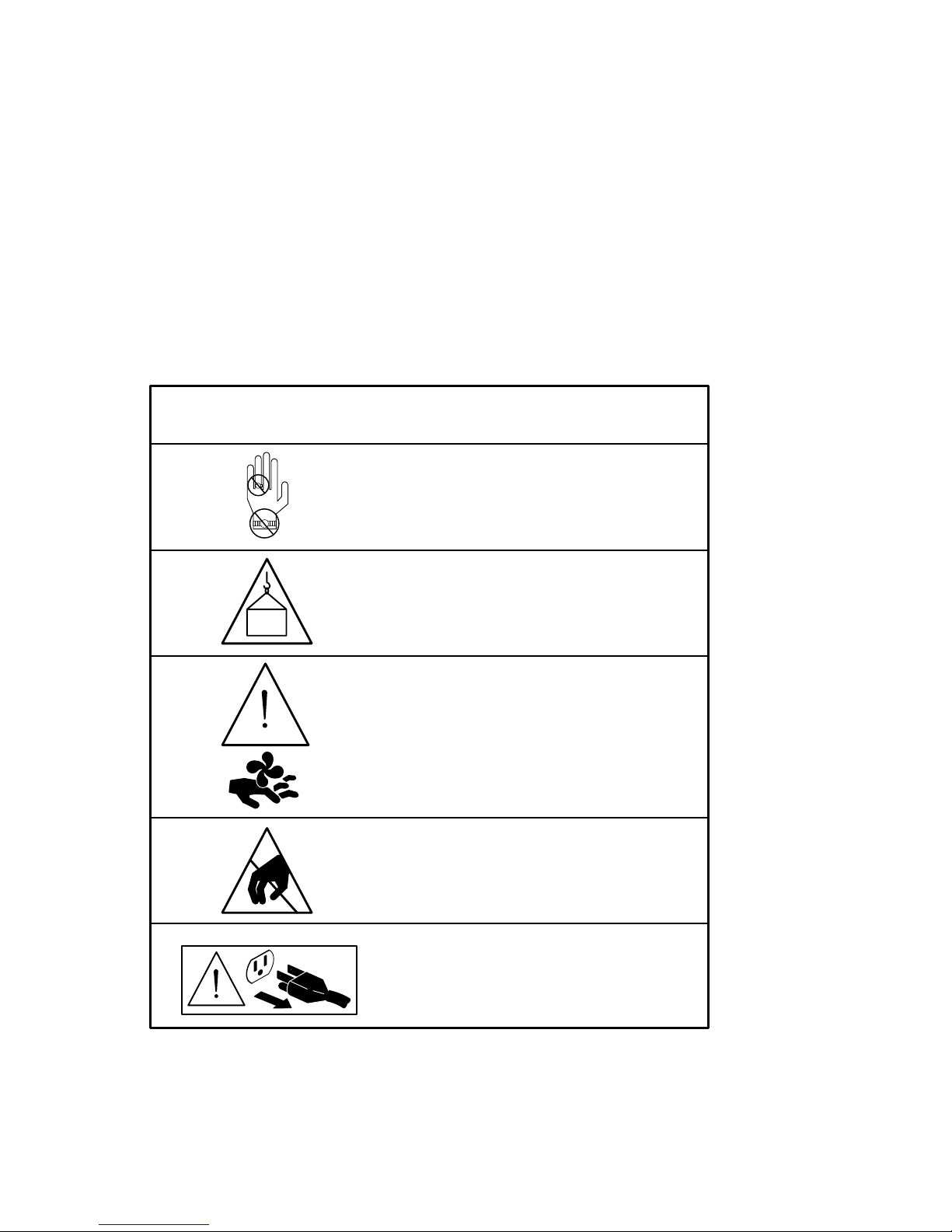
Figure 1 Safety Symbology
DescriptionSymbol
Danger – High Current
Do not wear metal objects.
Warning
40 kg
(88 lb)
The maximum weight of the DECNIS 600
is 40 kg (88 lb). At least two people are
required to lift the system.
Caution – Rotating Fans
After powering down the DECNIS 600,
wait at least 30 seconds before removing
the fan tray.
Electrostatic Sensitive Devices
Antistatic equipment must be attached
before handling.
Caution
Power down the DECNIS 600 before attempting the procedure marked with this
symbol.
LKG–5634-91I
xv
Page 16

Page 17

PartI
Installing the System
Part I contains all of the information that you need to install the DECNIS 600:
• Chapter 1 describes the preparations you need to make before installing
the DECNIS 600 unit.
• Chapter 2 shows how to install the DECNIS 600.
• Chapter 3 shows how to install Network Interface Cards into a system that
is powered down.
• Chapter 4 shows how to power up and test the installed system.
Page 18

Page 19

Preparing to Install the System
This chapter describes the preparations you need to make before installing the
DECNIS 600.
1.1 Tasks
Follow the procedures in Sections 1.2 to 1.6 to:
1. Plan a site for the DECNIS 600.
2. Prepare a rack (or cabinet) for the DECNIS 600.
3. Check that the site fulfills electrical requirements for the DECNIS 600.
4. Check the contents of the kit.
5. Check that you have the necessary tools available.
6. Check that two or more people are available to lift the DECNIS 600 from
its packaging and into the rack.
1.2 Planning a Site
1
Before you start the installation, plan and prepare the site for the DECNIS
600 so that:
• The site fulfills all electrical and environmental requirements for the
DECNIS 600. Appendix B describes these requirements.
• A rack is available and all rack requirements are fulfilled. Section 1.3
describes these requirements.
• The correct length of cabling is available for connecting the DECNIS 600 to
other equipment, for example, a modem.
• The site can accommodate plans to expand the system. For example, if
you require a Network Interface Card that uses a distribution panel, you
should allow room for the distribution panel in the rack or in a rack nearby.
Preparing to Install the System 1–1
Page 20

The dimensions of a Network Interface Card and its distribution panel (if
used) are specified on the Cabling Instructions and Specifications card. The
dimensions of the DECNIS 600 are shown in Section B.3.
1.3 Rack Requirements
The rack that you use for the DECNIS 600 must fulfill the requirements in
Section 1.3.1 to Section 1.3.4.
1.3.1 Dimensions
The DECNIS 600 can be installed in one of the following:
• NEP Hard Metric 600 mm rack
• Standard 19 inch rack
For example, the unit can be installed in the Digital H9A00 rack.
If you use the DECNIS 600 support brackets that are supplied as part of the
kit, the front and rear mounting rails on your rack or cabinet must be at least
47.63 cm (18.75 in) and no more than 80 cm (31.5 in) apart.
1.3.2 Stability
Make sure that the rack is stable:
• Extend any stabilizers available on the rack.
• If the rack has wheels, take one of the following actions to prevent them
rolling:
Jack the rack onto its feet (if available)
Apply the brakes (if available)
Wedge the wheels
Remove the wheels
• If possible, bolt the rack to the floor to prevent it from moving.
1.3.3 Power
If power is available from an outlet in the rack, check that sufficient power is
available to the DECNIS 600. Table B–1 shows the power requirements for the
DECNIS 600.
If power is available from an outlet outside the rack, for example, a wall socket,
check that the power cord from the DECNIS 600 reaches the outlet. The power
cord for the DECNIS 600 is 2 m (6.5 ft) long.
1–2 Preparing to Install the System
Page 21

1.3.4 Access
The following access is required so that the unit can be unpacked and installed:
• Remove any door on the front of the rack, or secure the door open.
• Clear a space of approximately 2 m (6.5 ft) at the front of the rack.
You will also need access to the rear of the rack to install the support brackets.
If possible, remove the rear door. If the rear of the rack is against a wall, make
sure that you can gain access from the front of the rack.
1.3.5 Position of the DECNIS 600
The DECNIS 600 can be installed in any position in the rack that satisfies the
following requirements:
• The position must conform to the published safety standard EN60950,
UL1950, CSA 950. This standard specifies important information about
the stability of rack mounted equipment.
• The position must satisfy the environmental requirements specified in
Appendix B.
If other equipment is installed in the rack, you should also check that
the DECNIS 600 does not affect the environmental requirements of that
equipment. For example, the DECNIS 600 should not be installed in a position
that restricts the air flow required for cooling other equipment.
1.4 Kit Contents
Figure 1–1 shows the contents of the kit as they are packed in the DECNIS
600 carton.
When you unpack the DECNIS 600, save the packaging materials and
carton in case you need to return any items.
If there are any items missing from the kit, or if any of the contents are
damaged, contact your Digital representative.
Note
Preparing to Install the System 1–3
Page 22
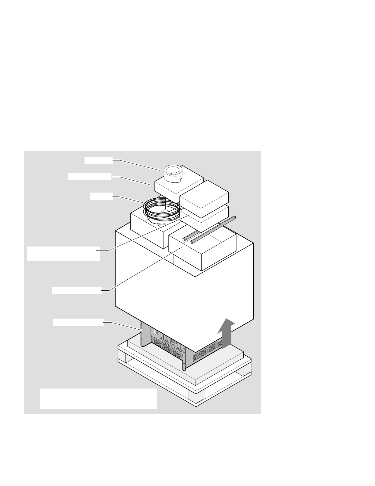
Figure 1–1 Kit Contents
Template
Documentation
Network Interface Cards
and loopback connectors
Support brackets
Cables
DECNIS 600 unit
Note: Some DECNIS 600 configurations
may be supplied with the Network
Interface Cards already installed
1–4 Preparing to Install the System
LKG-5635-91I
Page 23

1.5 Tools
Make sure you have the following equipment available:
• Template
The template is supplied with the DECNIS 600 kit. The markings on the
template correspond to the metric and imperial fixing holes on the DECNIS
600 unit and on the support brackets.
• Support brackets
Support brackets are supplied with the DECNIS 600 kit. These brackets
will fit all racks with front and rear vertical mounting rails that are
at least 47.63 cm (18.75 in) and no more than 80 cm (31.5 in) apart.
Section 2.4 describes how to fit the support brackets.
• Screwdrivers
You need the following screwdrivers for the DECNIS 600 installation:
• A Number 1 or Number 2 crosspoint screwdriver
• A3mm(
1.6 People
At least two people are required to lift the DECNIS 600 from its packaging
and into the rack.
1
in) flat blade screwdriver
8
The maximum weight of the DECNIS 600 with each slot occupied is
40 kg (88 lb). Each person must be capable and satisfied that they are
able to lift their share of the weight.
Preparing to Install the System 1–5
Page 24

Page 25

Installing the DEC Network Integration
This chapter describes how to unpack the DECNIS 600 and install it in a rack.
2.1 Tasks
Sections 2.2 to 2.6 show you how to:
1. Mark the position of the system in the rack
2. Install the clip nuts in the rack
3. Install the support brackets
4. Lift the system into the rack
5. Attach and tighten the screws
Section 2.7 describes what to do next.
2
Server 600
Installing the DEC Network Integration Server 600 2–1
Page 26
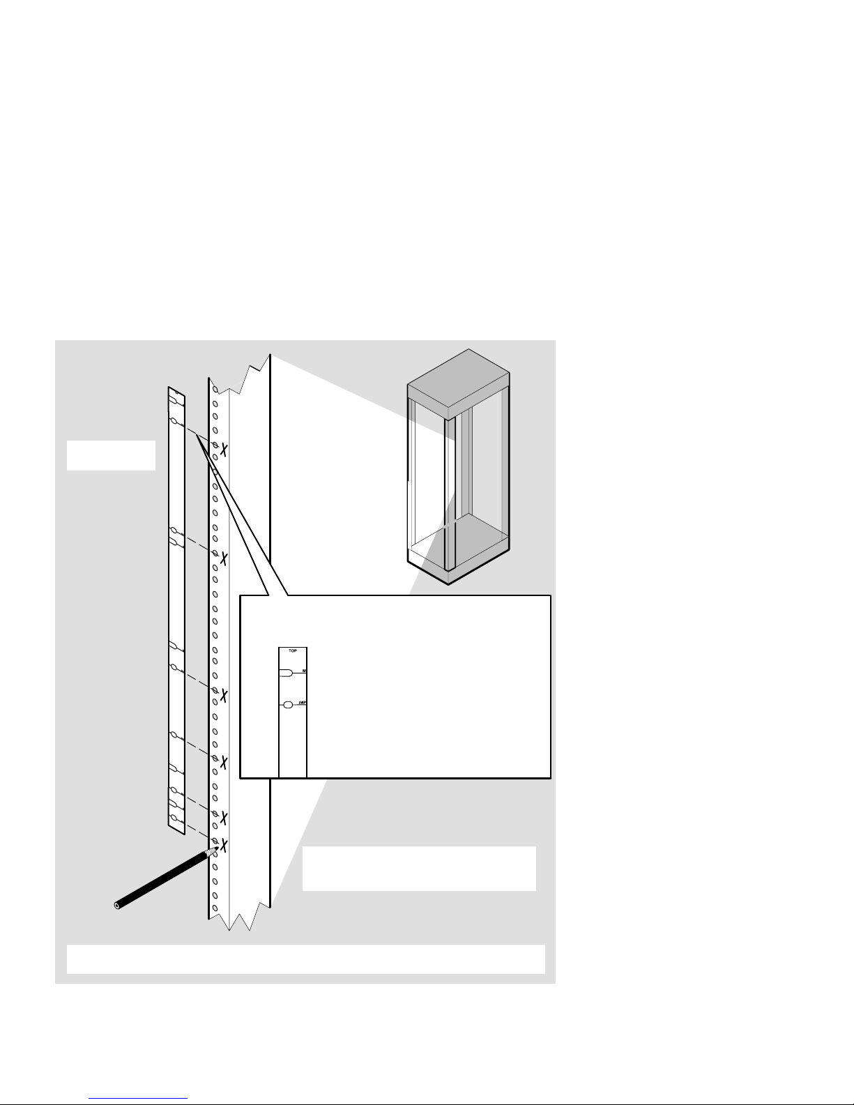
2.2 Mark a Position in the Rack
1. Position
template
2. Match template to holes in rails.
Use:
Metric markings for metric racks
Imperial markings for imperial racks
4. For the support brackets, repeat the procedure on the other 3 rails.
For the DECNIS 600 unit, repeat the procedure on the other front rail only
2–2 Installing the DEC Network Integration Server 600
3. Mark the position of the support
brackets and the DECNIS 600
unit in the rack
LKG–5636–91I
Page 27
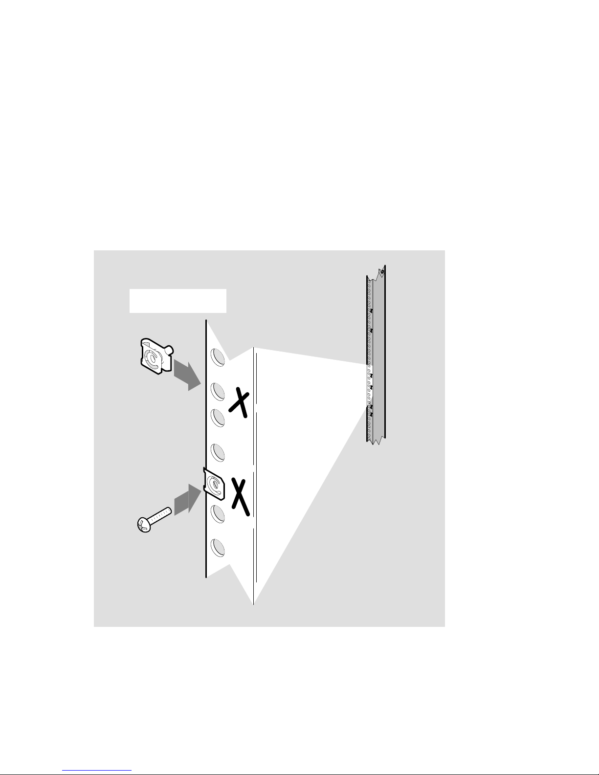
2.3 Install the Clip Nuts
Push clip nuts on to
marked holes
If the nuts and screws supplied with the DECNIS 600 are not suitable for your
rack, use appropriate fittings. Make sure that these are installed in the correct
position before installing the unit.
LKG–5637–91I
Installing the DEC Network Integration Server 600 2–3
Page 28
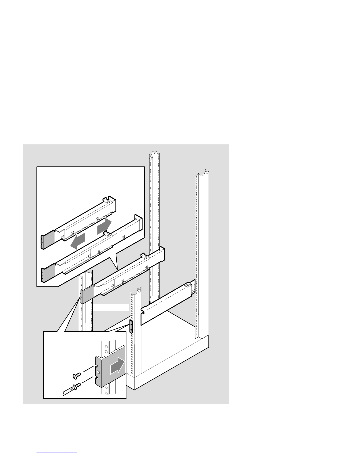
2.4 Install the Support Brackets
1. Extend the support brackets
to the depth of the rack
(80 cm (31.5 in) maximum)
Front of rack
2. Attach the side
supports to the
equipment rack.
Do not tighten
the screws
2–4 Installing the DEC Network Integration Server 600
LKG–5638–91I
Page 29
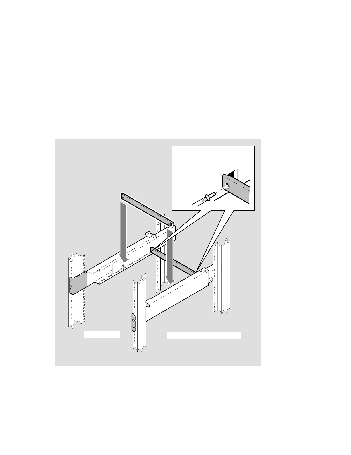
3. Attach the center supports,
starting with the rear bar
Front of rack
The DECNIS 600 support brackets are designed to provide support for the
DECNIS 600 unit and should remain in the rack after the installation is
complete.
4. Finally, tighten all screws
LKG–5639–91I
Installing the DEC Network Integration Server 600 2–5
Page 30
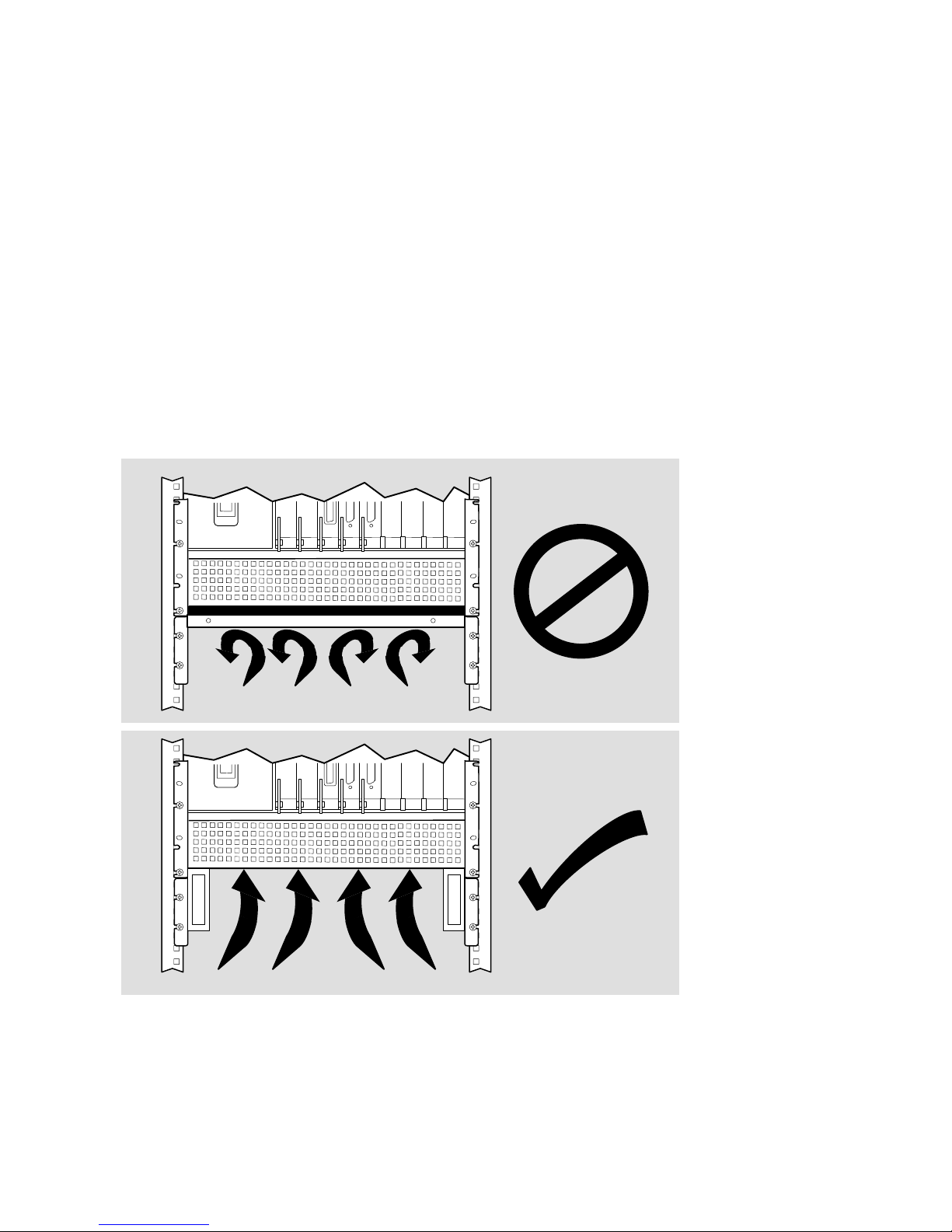
If the DECNIS 600 support brackets do not fit your rack, you can use brackets
or shelving supplied with your rack. However, make sure that:
• The rack brackets or shelves do not extend underneath the DECNIS 600
unit and block the vents on the bottom of the unit:
2–6 Installing the DEC Network Integration Server 600
LKG–5640–91I
Page 31

• The rack brackets or shelves do not cover the sides of the DECNIS 600:
LKG–6119–92I
Installing the DEC Network Integration Server 600 2–7
Page 32

2.5 Lift the System into the Rack
Warning
The maximum weight of the DECNIS 600 is 40 kg (88 lb). At least
two people are required to lift the system. Each person must be
competent and satisfied that they are able to lift their share of the
weight.
Avertissement
Le poids maximal du DECNIS 600 est de 40 kg. Au moins deux
personnes sont requises pour soulever le système. Chaque personne
doit être convaincue de pouvoir soulever sa part du poids.
40 kg
(88 lb)
Der DECNIS 600 wiegt maximal 40 kg. Zum Anheben des Systems
sind mindestens zwei Personen erforderlich.
Il massimo peso del DECNIS 600 è di 40 kg. Sono richieste almeno due
persone per sollevare il sistema. Entrambe devono essere certe di poter
sollevare la propria parte di peso.
El peso máximo del DECNIS 600 es de 40 kg, por lo que son necesarias
al menos dos personas para levantar el sistema.
2–8 Installing the DEC Network Integration Server 600
Warnung
Attenzione
Aviso
Page 33

Aviso
O peso máximo do DECNIS 600 é de 40 kg (88 lb). São necessárias, no
mínimo, duas pessoas para levantar o sistema. Cada pessoa deve estar
apta a levantar a sua parte do peso do sistema.
Waarschuwing
Het maximumgewicht van de DECNIS 600 is 40 kg (88 lb). Er zijn
minimaal twee personen nodig om het systeem op te tillen. Deze
personen moeten fit zijn en in staat hun deel van het gewicht te
dragen.
Advarsel
Den maksimale vægt af DECNIS 600 er 40 kg og der bør være mindst
to personer til at løfte systemet.
Varoitus
DECNIS 600 painaa enintään 40 kg. Järjestelmän nostamiseen
tarvitaan vähintään kaksi ihmistä.
DECNIS 600 veier inntil 40 kg, og bør løftes av minst to personer.
DECNIS 600 väger maximalt 40 kg (88 lb). Minst två personer
krävs för att lyfta maskinen. Varje person måste vara medveten om
maskinens vikt och säker på att klara att lyfta den.
Advarsel
Varning
Installing the DEC Network Integration Server 600 2–9
Page 34

2–10 Installing the DEC Network Integration Server 600
Page 35

Rack
Support
brackets
LKG-5678-91I
Installing the DEC Network Integration Server 600 2–11
Page 36

2.6 Attach the Screws
1. Attach screws
2. Tighten
screws
2–12 Installing the DEC Network Integration Server 600
LKG–5641–91I
Page 37

2.7 What to Do Next
If your DECNIS 600 system is supplied with its Network Interface Cards
already installed, you should now:
1. Follow the instructions on each of the Cabling Instructions and
Specifications cards provided for the Network Interface Cards. The
cards show how to install a distribution panel (if one is included as part of
the Network Interface Card kit) and attach the communications cables.
2. Go to Section 3.9 for instructions on how to enable each Network Interface
Card and Section 3.10 for details of what to do next.
If your DECNIS 600 system does not have any Network Interface Cards
installed, go to Chapter 3 for instructions on how to install the Network
Interface Cards.
Do not power up the system until the Network Interface Cards have
been installed.
Installing the DEC Network Integration Server 600 2–13
Page 38

Page 39

Installing the Network Interface Cards
This chapter shows how to install a Network Interface Card into the DECNIS
600 when it is powered down.
Some DECNIS 600 configurations are supplied with the Network Interface
Cards already installed. If your system arrives with all cards installed, follow
the procedures in Sections 3.7 to 3.10 only.
If you want to install a Network Interface Card in a running system, refer to
Chapter 5.
3.1 Tasks
Complete the procedures in Sections 3.2 to 3.9 to:
1. Prepare to install the Network Interface Card
2. Check that the system is switched off
3. Attach the static protection equipment
4. Remove the slot cover
3
5. Install the Network Interface Card
6. Install the distribution panel (if included as part of the Network Interface
Card kit)
7. Attach the communications cables
8. Enable the Network Interface Card
Installing the Network Interface Cards 3–1
Page 40

3.2 Preparation
Before you begin the installation procedure, check the contents of the Network
Interface Card kit. The Cabling Instructions and Specifications card for the
Network Interface Card lists the contents of the kit.
Do not remove the Network Interface Card from its antistatic
packaging until you have completed the procedures in Section 3.4.
The packaging protects the card from damage caused by static
discharge.
When you unpack the kit, keep all of the packaging in case you need to remove
and replace the Network Interface Card.
If any part of the kit is missing or damaged, contact your local Digital
representative.
3.2.1 Tools
You will need the following tools for the Network Interface Card installation:
• Antistatic kit that includes an antistatic wrist strap and antistatic mat
• A3mm(
1
in) flat blade screwdriver
8
Note
3.2.2 Network Interface Card Position
The Network Interface Cards can be installed in slots 3 to 9 in any order.
However, each time that a Network Interface Card is moved to a different slot,
the software configuration utilities must be run (see the software configuration
documentation for more information). For this reason, Digital recommends
that Network Interface Cards remain in the same slot wherever possible.
Management of the DECNIS 600 may be made easier if Network Interface
Cards of the same type are grouped together. Management of several network
systems may also be made easier if the organization of line configurations are
consistent. For example, LAN cards could be installed from slot 9 towards slot
3, and WAN cards from slot 3 towards slot 9.
3–2 Installing the Network Interface Cards
Page 41

3.3 Check the System Is Switched Off
Set power
switch to
0 (OFF)
LKG–5642–91I
Installing the Network Interface Cards 3–3
Page 42

3.4 Attach the Static Protection Equipment
2. Attach clip to
DECNIS 600
(unpainted
section)
4. Attach clip to
DECNIS 600
(unpainted
section)
1. Place mat on
work surface
3–4 Installing the Network Interface Cards
3. Put on
wrist strap
LKG–5643–91I
Page 43

3.5 Remove the Slot Cover
1. Loosen screws
2. Remove
from unit
3. Store slot cover
for future use
LKG–5644–91I
Installing the Network Interface Cards 3–5
Page 44

3.6 Install the Card into the System
2. Move the handles outwards
and position the card
in the slot
1. Check that the
NIC switch is
down (disabled)
3. Check that the
guide pins are
in line with the
pin holes on
the unit
3–6 Installing the Network Interface Cards
LKG–5645–91I
Page 45

4. GENTLY slide the
card into the unit,
locating the pins
in the holes
5. Move handles
inward to seat
card into unit
6. Secure screws.
Do not overtighten
Max. torque =
4.95 cm kg
(4.3 in lb)
Note: If there is any resistance,
gently remove the card
and locate its position again
LKG–5646-91I
Installing the Network Interface Cards 3–7
Page 46

3.7 Install the Distribution Panel
If a distribution panel is included as part of the Network Interface Card kit,
install the panel in the rack before you install the communications cables.
The Cabling Instructions and Specifications card for the Network Interface
Card describes how to install the distribution panel.
3.8 Attach the Communications Cables
Follow the procedures on the Cabling Instructions and Specifications card to
attach all communications cables for the Network Interface Card.
3–8 Installing the Network Interface Cards
Page 47

3.9 Enable the Network Interface Card
Move the
switch up
The Network Interface Card switch enables the card so that it is automatically
powered up and tested when the DECNIS 600 is powered up.
LKG–5647–91I
Installing the Network Interface Cards 3–9
Page 48

3.10 What to Do Next
Complete the following steps:
• Follow the procedures in Chapter 4 to power up and test the installed
system.
• Complete the Network Interface Card Configuration Card and place it in
the pocket inside the DECNIS 600 documentation binder.
• Store the packaging in a safe place in case you need to remove the Network
Interface Card from the system. In particular, it is important to keep the
antistatic bag.
• Store any removed slot covers for future use. Each slot in the DECNIS
600 must either contain a card or be covered with a slot cover so that the
system cooling fans and temperature sensors can operate correctly.
3–10 Installing the Network Interface Cards
Page 49

Testing the Installed System
This chapter describes how to power up and check the installed system.
4.1 Tasks
Follow the procedures in Sections 4.2 to 4.5 to:
1. Check the Network Interface Card installations
2. Power up the system
3. Monitor the power module LEDs
4. Monitor the system displays and LEDs
4.2 Check the Network Interface Card Installations
Before you power up the DECNIS 600, check that:
1. The Network Interface Cards are installed correctly and enabled.
2. The communications cables are installed correctly. Refer to the Cabling
Instructions and Specifications card for details of how to install the cables.
4
Testing the Installed System 4–1
Page 50

4.3 Power Up the System
1. Set power
switch to
0 (OFF)
2. Insert power
cord into unit
3. Insert power
cord into
outlet
4. Set power
switch to
1 (ON)
4–2 Testing the Installed System
5. Tie back power cord
to horizontal crossbars
LKG-5648-91I
Page 51

4.4 Monitor the Power Module LEDs
OVERVOLTAGE
LED (Red)
OVERCURRENT
LED (Yellow)
MODULE OK
LED (Green)
The MODULE OK LED should light approximately one second after power
up. Check Table 4–1 for the state displayed by the LEDs and then take the
corresponding action.
LKG–5649–91I
Testing the Installed System 4–3
Page 52

Table 4–1 Power Module LED States
LED State Action
MODULE OK Go to Section 4.5 to monitor the other displays on the unit.
No LEDs lit within 5
seconds of power up
Complete the following:
1. Move the power switch to 0 (OFF)
2. Unplug the power cable from the power outlet
Then follow the procedures in Section 10.3.
OVERVOLTAGE Power down the DECNIS 600 and follow the procedures in
OVERCURRENT Power down the DECNIS 600 and follow the procedures in
Chapter 9.
Chapter 9.
4.5 Monitor the System Displays and LEDs
On power up, the DECNIS 600 automatically tests each module and then tests
the operation of the installed system:
1. Module self-test
The DECNIS 600 activates a module self-test on each card that is installed
and enabled. The module self-test checks the card for faults.
2. System self-test
When each card has completed its module self-test, the DECNIS 600 runs
a system self-test. This test checks that each card can interact with the
rest of the system. It then runs a diagnostic check to test the operation of
the whole system.
4–4 Testing the Installed System
Page 53

The progress of these tests is shown on the system displays located on the
processor card and on the card LEDs:
Processor card
Memory card
System
self-test
display
HOTSWAP LEDs
System
operation
display
FAULT LEDs
READY LEDs
LKG–5651–91I
Testing the Installed System 4–5
Page 54

On power up, testing takes place in the following order:
1. The READY LEDs on the processor card and Network Interface Cards flash
on and off (one flash per second), indicating that the cards are running
module self-test:
Processor card
Memory card
The memory card is not tested (no LEDs lit) until the processor card has
successfully completed its module self-test.
When the processor card has passed module self-test, its READY LED
remains lit and the memory card starts module self-test. The memory
card’s READY LED flashes (one flash per second) to indicate that testing is
in progress.
4–6 Testing the Installed System
READY LEDs
flashing
LKG–5652–91I
Page 55

2. As soon as the memory card has passed module self-test and its READY
LED remains lit, the Network Interface Cards interact with it as part of
their module self-test. At this point, their READY LEDs flicker (8 flashes
per second):
When a Network Interface Card has successfully completed its module
self-test, its READY LED remains lit.
If the FAULT LED is lit on any of the cards, refer to Section 4.7.
READY LEDs
flickering
LKG–5653–91I
Testing the Installed System 4–7
Page 56

3. The DECNIS 600 then tests the whole system, including all Network
Interface Cards that pass module self-test. The displays on the processor
card show that the system self-test is in progress:
READY
LEDs lit
READY
LEDs lit
4–8 Testing the Installed System
Pattern runs up
and down over
both system
displays (one
segment lights
at a time)
LKG–5654–91I
Page 57

4. When testing is complete, the system self-test display shows the value 0 to
indicate that no faults were found and the system operation display shows
the progress of load operations (see Section 4.6):
READY
LEDs lit
READY
LEDs lit
If the system self-test display shows the value 1 or 2, or if it does not
display a value, follow the procedures in Section 9.2.
System
self-test
display
System
operation
display
LKG–5655–91I
Testing the Installed System 4–9
Page 58

4.6 Loading the DECNIS 600
If the system testing is successful, the DECNIS 600 automatically sends a load
request over its circuits. The system operation (lower) display on the processor
card shows the progress of the load.
For example, the following sequence of codes is shown on the system operation
display if the software is already installed and the load is successful:
Display Code Description
The value 7 in the lower display indicates that the
DECNIS 600 is sending a load request over all
circuits in an attempt to find a load host.
The value 2 in the lower display indicates that the
DECNIS 600 is loading a load host and is loading
software. This code is displayed while the load is
taking place.
The value 4 in the lower display indicates that the
software is loaded.
A circling pattern (two segments light at a time) in
the lower display indicates that the software is
running successfully .
Circling pattern
4–10 Testing the Installed System
LKG–5656–91I
Page 59

Figure A–2 shows all of the codes that are displayed on the system operation
display. If the displayed codes indicate that the system is loaded, or waiting
to load, refer to Section 4.8 for details of what to do next. If the displayed
codes indicate that there is a problem, refer to Section 9.2 for problem solving
procedures.
4.7 What to Do if Things Go Wrong
Check Table 4–2 for LED state shown and take the corresponding action.
Table 4–2 Problems at Power Up
Symptom Action
Processor card FAULT LED lit Follow the procedures in Section 10.6.
Memory card FAULT LED Follow the procedures in Section 10.7.
No LEDs lit on Network
Interface Card
Network Interface Card FAULT
LED
Network Interface Card FAULT
and READY LEDs lit
Network Interface Card READY
LED continuously flashing
Card is not enabled, may be faulty or have faulty
connections. Refer to Section 3.9 to enable card. If
problem persists, go to Section 10.10.
A diagnostic error was found on the Network
Interface Card. Go to Section 10.9.
Network Interface Card is in the ATTENTION
state. A diagnostic error was found on the card or
cables associated with it. Go to Section 10.9.
Network Interface Card not configured. Refer to
the software documentation for details of how to
configure the card.
4.8 What to Do Next
When the system displays show that the DECNIS 600 is running successfully:
1. Complete the DEC Network Integration Server 600 Configuration card and
the Network Interface Card configuration cards.
2. If the software is not installed, follow the procedures on the DEC Network
Integration Server Installation card to install the software.
Testing the Installed System 4–11
Page 60

Page 61

PartII
Upgrading and Removing the System
Part II shows you how to upgrade and remove the system:
• Chapter 5 shows how to install additional Network Interface Cards without
powering down the system.
• Chapter 6 shows how to install a processor card or memory card.
• Chapter 7 shows how to remove Network Interface Cards from the system.
• Chapter 8 shows how to remove the DECNIS 600 unit.
Page 62

Page 63

5
Adding Network Interface Cards to a
Running System
This chapter shows how to install a Network Interface Card in a running
DECNIS 600 system. Using this procedure, you can:
• Install a new Network Interface Card into a previously unused slot without
powering down the system. The card performs a module self-test and, if it
passes, is available for use by the software.
• ‘Hotswap’ or replace a Network Interface Card while the system is running.
To hotswap a Network Interface Card:
1. Follow the procedures in Chapter 7 to remove the Network Interface
Card.
2. Follow the procedures in this chapter to install a new Network
Interface Card in the same slot.
Note
Before you hotswap a Network Interface Card, consult the
documentation for the software you are using with the DECNIS 600.
The hotswap procedure may affect the state of the Network Interface
Card software.
Adding Network Interface Cards to a Running System 5–1
Page 64

5.1 Tasks
Follow the procedures in Sections 5.2 to 5.9 to:
1. Prepare to install the Network Interface Card
2. Attach the static protection equipment
3. Remove the slot cover that covers the system slot
4. Install the card in the system
5. Install the distribution panel (if supplied)
6. Attach the communications cables
7. Enable the Network Interface Card
8. Monitor the Network Interface Card LEDs
5.2 Preparation
Before you begin the installation procedure, check the contents of the Network
Interface Card kit. The Cabling Instructions and Specifications card for the
Network Interface Card lists the contents of the kit.
Do not remove the Network Interface Card from its antistatic
packaging until you have completed the procedures in Section 3.4.
The packaging protects the card from damage caused by static
discharge.
Note
When you unpack the kit, keep all of the packaging in case you need to remove
and replace the Network Interface Card.
If any part of the kit is missing or damaged, contact your local Digital
representative.
Before you start, do not power down the system.
5–2 Adding Network Interface Cards to a Running System
Page 65

5.2.1 Tools
You will need the following tools for the Network Interface Card installation:
• Antistatic kit that includes an antistatic wrist strap and antistatic mat
• 3 mm (
1
in) flat blade screwdriver
8
5.2.2 Network Interface Card Position
The Network Interface Card can be installed in slots 3 to 9 in any order.
However, each time that a Network Interface Card is moved to a different slot,
the software configuration utilities must be run (see the software configuration
documentation for more information). For this reason, Digital recommends
that Network Interface Cards remain in the same slot wherever possible.
Management of the DECNIS 600 may be made easier if Network Interface
Cards of the same type are grouped together. Management of several network
systems may also be made easier if the organization of line configurations are
consistent. For example, LAN cards could be installed from slot 9 towards slot
3, and WAN cards from slot 3 towards slot 9.
Adding Network Interface Cards to a Running System 5–3
Page 66

5.3 Attach the Static Protection Equipment
2. Attach clip to
DECNIS 600
(unpainted
section)
4. Attach clip to
DECNIS 600
(unpainted
section)
1. Place mat on
work surface
5–4 Adding Network Interface Cards to a Running System
3. Put on
wrist strap
LKG–5643–91I
Page 67

5.4 Remove the Slot Cover
1. Loosen screws
2. Remove
from unit
3. Store slot cover
for future use
LKG–5644–91I
Adding Network Interface Cards to a Running System 5–5
Page 68

5.5 Install the Card into the System
Remove the Network Interface Card from its antistatic packaging and complete
the steps shown in the diagrams on the following pages.
Danger—High Current
Do not wear metal objects.
Danger—Courants Élévés
Ne portez pas d’objets métalliques.
Gefahr—Hohe Stromstärken
Tragen Sie keine Metall-Gegenstände an Händen und Armen.
Pericolo—Corrente elettrica elevata
Non indossare oggetti metallici.
Peligro—Corriente eléctrica de alta intensidad
No llevar ningún objeto metálico.
5–6 Adding Network Interface Cards to a Running System
Page 69

Perigo—Corrente Elevada
Não usar objectos metálicos.
Gevaar—Hoge Stroom
Draag geen metalen voorwerpen.
Fare—Stærkstrøm
Pas på metalobjekter.
Vaara: voimakas sähkövirta
Älä käytä metalliesineitä.
Fare—Sterkstrøm
Ta av eventuelle metallgjenstander.
Fara—högström
Bär inga metallföremål.
Adding Network Interface Cards to a Running System 5–7
Page 70

2. Move the handles outwards
and position the card
in the slot
1. Check that the
NIC switch is
down (disabled)
3. Check that the
guide pins are
in line with the
pin holes on
the unit
5–8 Adding Network Interface Cards to a Running System
LKG–5645–91I
Page 71

4. GENTLY slide the
card into the unit,
locating the pins
in the holes
5. Move handles
inward to seat
card into unit
6. Secure screws.
Do not overtighten
Max. torque =
4.95 cm kg
(4.3 in lb)
Note: If there is any resistance,
gently remove the card
and locate its position again
LKG–5646-91I
Adding Network Interface Cards to a Running System 5–9
Page 72

5.6 Install the Distribution Panel
If a distribution panel is included as part of the Network Interface Card kit,
install the panel in the rack before you install the communications cables.
The Cabling Instructions and Specifications card for the Network Interface
Card describes how to install the distribution panel.
5.7 Attach the Communications Cables
Follow the procedures on the Cabling Instructions and Specifications card to
attach all communications cables for the Network Interface Card.
5–10 Adding Network Interface Cards to a Running System
Page 73

5.8 Enable the Network Interface Card
Move the
switch up
When you enable the Network Interface Card, a module self-test is activated.
This test detects any faults on the Network Interface Card and checks that the
Network Interface Card can interact with the running system.
The module self-test can also be used to provide loopback testing on a Network
Interface Card. The Network Interface Card Problem Solving card describes
how to run a loopback test by fitting a loopback connector and enabling the
card.
LKG–5647–91I
Adding Network Interface Cards to a Running System 5–11
Page 74

5.9 Monitor the Network Interface Card LEDs
HOTSWAP LED
(Yellow)
FAULT LED
(Yellow)
READY LED
(Green)
The progress and results of the module self-test are shown on the Network
Interface Card LEDs:
1. The READY LED flashes (one flash per second). This indicates that the
module self-test is in progress.
2. The READY LED flickers (eight flashes per second). This indicates that
the Network Interface Card has passed its module self-test and is waiting
to load. Refer to Section 5.11.
If the FAULT LED or HOTSWAP LED is lit, or there are no LEDs lit on the
Network Interface Card, refer to Figure 5–1.
5–12 Adding Network Interface Cards to a Running System
LKG–5659-91I
Page 75

Figure 5–1 Network Interface Card States
NIC
(flashing)
(flicker)
State ActionLEDS
No LED lit
Testing in
progress
Loading
FAULT
Either:
– The card is not installed correctly
– There is a fault on the card or the slot
Follow the procedures in Section 5.10.
The module self-test is running on the
card (1 flash per second).
The Network Interface Card is either waiting to
load or the software is loading.
Refer to Section 5.11.
The module self-test has failed. There may
be a fault on the Network Interface Card.
Follow the procedures in Section 5.10.
ATTENTION
HOTSWAP
The Network Interface Card is running, but
not all ports on the card are usable.
Follow the procedures in Section 5.10.
The Network Interface Card is disabled
(switch is down). Follow the procedures in
Section 5.8 to enable the card.
LKG–5660-91I
Adding Network Interface Cards to a Running System 5–13
Page 76

5.10 What to Do if Things Go Wrong
Check Table 5–1 for the Network Interface Card state and take the
corresponding action.
Table 5–1 Network Interface Card Installation Problems
LED State Action
No LEDs lit
on Network
Interface Card
FAULT or
ATTENTION
Complete the following steps:
1. Check that the Network Interface Card is installed correctly.
The Network Interface Card must be inserted into the DECNIS
600 and the handles moved inwards so that the card is seated
in the correct position. See Section 5.5.
2. Follow the procedures in Section 10.10.
Complete the following steps:
1. Check that all of the cables are installed correctly. Follow the
procedures on the Cabling Instructions and Specifications card
for the Network Interface Card.
2. Follow the procedures in Section 10.9.
5–14 Adding Network Interface Cards to a Running System
Page 77

5.11 What to Do Next
Complete the following steps:
• Complete the Network Interface Card Configuration Card and place it in
the pocket inside the DECNIS 600 documentation binder.
• Configure the software system as necessary. Refer to the software
configuration documentation for your load-host system.
• Store the packaging in a safe place in case you need to remove the Network
Interface Card from the system. In particular, it is important to keep the
antistatic bag.
• Store any removed slot covers for future use. Each slot in the DECNIS 600
must either contain a card or be covered by a slot cover so that the system
cooling fans and temperature sensors can operate correctly.
Adding Network Interface Cards to a Running System 5–15
Page 78

Page 79

Installing Upgraded Processor or Memory
Cards
This chapter describes how to remove the processor card and memory card and
install new cards into the DECNIS 600 unit.
6.1 Tasks
Complete the procedures in Sections 6.2 to 6.11 to:
1. Prepare for the installation
2. Power down the system
3. Attach the static protection equipment
4. Remove the protective cover
5. Remove the processor card or memory card
6. Install the new processor card or memory card
7. Replace the protective cover
6
8. Power up the system
9. Monitor the card displays
10. Monitor the system displays
Installing Upgraded Processor or Memory Cards 6–1
Page 80

6.2 Preparation
Remove the cardboard packaging from the processor card or the memory card.
Do not remove the card from its antistatic packaging until you have
completed the procedures in Section 6.4. The packaging protects the
card from damage caused by static discharge.
When you unpack the kit, keep all of the card packaging in case you need to
remove and replace the card.
6.2.1 Tools
Make sure you have the following available:
• Antistatic kit that includes an antistatic wrist strap and antistatic mat
• A3mm(
6.2.2 Card Position
The processor card and the memory card must be installed in slots 1 or 2.
1
in) flat blade screwdriver
8
Note
6–2 Installing Upgraded Processor or Memory Cards
Page 81

6.3 Power Down the System
1. Set power
switch to
0 (OFF)
2. Remove
power cord
from outlet
3. Remove
power
cord from
unit
LKG-5661–91I
Installing Upgraded Processor or Memory Cards 6–3
Page 82

6.4 Attach the Static Protection Equipment
2. Attach clip to
DECNIS 600
(unpainted
section)
4. Attach clip to
DECNIS 600
(unpainted
section)
1. Place mat on
work surface
6–4 Installing Upgraded Processor or Memory Cards
3. Put on
wrist strap
LKG–5643–91I
Page 83

6.5 Remove the Protective Cover
1. Loosen
screws
2. Remove
cover
LKG–5662-91I
Installing Upgraded Processor or Memory Cards 6–5
Page 84

6.6 Remove the Processor Card or Memory Card
Caution
Power down the DECNIS 600 before attempting these procedures.
Atención
Desconectar el DECNIS 600 antes de realizar estos procedimientos.
Advarsel
Slå av strømtilførselen til DECNIS 600 før du utfører disse oppgavene.
Desligar o DECNIS 600 antes de efectuar estes procedimentos.
Schalten Sie den DECNIS 600 ab, bevor Sie diese Arbeiten ausführen.
Spegnere il DECNIS 600 prima di eseguire queste procedure.
6–6 Installing Upgraded Processor or Memory Cards
Atenção
Vorsicht
Avvertenza
Page 85

HUOM:
Sammuta virta DECNIS 600:sta ennen kuin ryhdyt näihin
toimenpiteisiin.
Voorzichtig
Schakel de DECNIS 600 uit voordat u deze procedures probeert uit te
voeren.
Varning
Slå av strömmen på DECNIS 600 innan dessa procedurer utförs.
Advarsel
Sluk for DECNIS 600 før disse operationer påbegyndes.
Attention
Veuillez couper l’alimentation du DECNIS 600 avant d’effectuer ces
procédures.
Installing Upgraded Processor or Memory Cards 6–7
Page 86

2. Gently pull
handles
outwards
1. Loosen
screws
LKG–5663-91I
6–8 Installing Upgraded Processor or Memory Cards
Page 87

3. Slide card
out of unit
4. Reset handles
5. Replace card in antistatic
packaging
LKG–5664-91I
Installing Upgraded Processor or Memory Cards 6–9
Page 88

6.7 Install the New Processor Card or Memory Card
1. Move the handles outwards
and GENTLY slide the card
halfway into the slot
6–10 Installing Upgraded Processor or Memory Cards
2. Check that the
guide pins are
in line with the
pin holes on
the unit
LKG–5665-91I
Page 89

3. Gently slide the
card into the unit,
locating the pins
in the holes
4. Move handles
inward to seat
card into unit
5. Secure screws
Do not overtighten
Max. torque =
4.95 cm kg (4.3 in lb)
Note: If there is any resistance,
gently remove the card
and locate its position again
LKG–5666-91I
Installing Upgraded Processor or Memory Cards 6–11
Page 90

6.8 Replace the Protective Cover
1. Replace
cover
2. Secure screws
Do not overtighten
Max. torque =
4.95 cm kg (4.3 in lb)
6–12 Installing Upgraded Processor or Memory Cards
LKG–5667-91I
Page 91

6.9 Power Up the System
1. Insert
power
cord into
unit
2. Insert power
cord into
outlet
3. Set power
switch to
1 (ON)
4. Tie back power cord
to horizontal crossbars
LKG-5668–91I
Installing Upgraded Processor or Memory Cards 6–13
Page 92

6.10 Monitor the Card LEDs
FAULT LED
(Yellow)
READY LED
(Green)
Processor card
Memory card
On power up, the READY LED on the processor card flashes (one flash per
second). This indicates that the card is running its module self-test.
After 30–40 seconds, its READY LED should remain lit to indicate that the
test was successful. Then, the memory card starts its module self-test and its
READY LED flashes (one flash per second).
The DECNIS 600 activates a module self-test on the processor card, memory
card, and the Network Interface Cards each time that the system is powered
up.
6–14 Installing Upgraded Processor or Memory Cards
FAULT LED
(Yellow)
LKG–5669-91I
Page 93

Check Figure 6–1 for the LED state displayed on the processor card and
memory card and details of what to do next.
Figure 6–1 Processor Card and Memory Card LED States
LEDs State Action
The module self-test was successful and the
READY
card is running.
Follow the procedures in Section 6.11.
Possible causes:
– The card is waiting to run its module self-test.
See Section 6.10.
– The card is not installed correctly.
See Section 6.12.
– There is a fault on the card or with the slot.
(No LEDs lit)
Card
waiting or
disabled
See Section 6.12.
Testing in
Flashing
(1 flash per second)
progress
FAULT
The module self-test is running on the
card.
The module self-test has failed.
Follow the procedures in Section 6.12.
LKG–5670–91I
Installing Upgraded Processor or Memory Cards 6–15
Page 94

6.11 Monitor the System Displays
Processor card
System
self-test
display
System
operation
display
Appendix A describes the codes shown on the two system displays. If the
displays indicate that there is a problem with the DECNIS 600 system, follow
the procedures in Chapter 9 to identify and solve the problem.
6–16 Installing Upgraded Processor or Memory Cards
LKG–5671-91I
Page 95

6.12 What to Do if Things Go Wrong
Check Table 6–1 for the LED state displayed and take the corresponding
action.
Table 6–1 Processor Card and Memory Card Installation Problems
LED State Action
No LEDs lit Complete the following:
1. Check that the power cord is connected and that the power
module LEDs show that there is power to the unit. See
Section 4.4.
2. Check that the card is installed correctly. The card must
be inserted into the DECNIS 600 and the handles moved
inwards so that the card is seated in the correct position.
See Section 6.7.
3. The card may be faulty or there may be a problem with the
slot. Follow the procedures in Chapter 9.
FAULT The card has failed its module self-test. Remove the card and
replace it with a new processor card or memory card. If there is
still a problem, follow the procedures in Chapter 9.
Installing Upgraded Processor or Memory Cards 6–17
Page 96

Page 97

This chapter describes how to remove a Network Interface Card from a
DECNIS 600 running system.
7.1 Tasks
Complete the procedures in Sections 7.2 to 7.7 to:
1. Prepare to remove the card
2. Attach the static protection equipment
3. Disable the Network Interface Card
7
Removing Network Interface Cards
Note
If you want to hotswap a Network Interface Card, consult the
documentation for the software you are using with the DECNIS 600
before you remove the card. The hotswap procedure may affect the
Network Interface Card software.
4. Detach the communications cables
5. Remove the Network Interface Card
6. Replace the slot cover
7.2 Preparation
Make sure you have the following available:
• Antistatic kit that includes an antistatic wrist strap and antistatic mat
• A3mm(
• Antistatic bag and packaging for the Network Interface Card
1
in) flat blade screwdriver
8
Removing Network Interface Cards 7–1
Page 98

7.3 Attach the Static Protection Equipment
2. Attach clip to
DECNIS 600
(unpainted
section)
4. Attach clip to
DECNIS 600
(unpainted
section)
1. Place mat on
work surface
7–2 Removing Network Interface Cards
3. Put on
wrist strap
LKG–5643–91I
Page 99

7.4 Disable the Network Interface Card
1. Move the
switch down
2.
Wait for
HOTSWAP
LED to light
7.5 Detach the Communications Cables
When the HOTSWAP LED is lit, you can remove all cables connected to
the Network Interface Card ports. Follow the procedures on the Cabling
Instructions and Specifications card for the Network Interface Card.
Note that if the Network Interface Card has a separate distribution panel, you
must also remove the cables from the panel. See the Cabling Instructions and
Specifications card for more information.
LKG–5672-91I
Removing Network Interface Cards 7–3
Page 100

7.6 Remove the Network Interface Card
1. Loosen
screws
2. Gently pull
handles
outwards
7–4 Removing Network Interface Cards
LKG–5673-91I
 Loading...