

DEC 3000 Model 400S, DEC 3000 Model 700S, DEC 3000 Model 600S Installation & Owner's Manual

DEC3000Model400S/600S/700S
AXPRackmountServer
Installation/Owner’sGuide
Order Number: EK–RSNDP–IN. C01
Revision/Update Information: This is a revised document.
Digital Equipment Corporation
Maynard, Massachusetts

August 1994
Digital Equipment Corporation makes no representations that the use of its
products in the manner described in this publication will not infringe on
existing or future patent rights, nor do the descriptions contained in this
publication imply the granting of licenses to make, use, or sell equipment or
software in accordance with the description.
No responsibility is assumed for the use or reliability of software on equipment
that is not supplied by Digital Equipment Corporation or its affiliated
companies.
Restricted Rights: Use, duplication, or disclosure by the U.S. Government is
subject to restrictions as set forth in subparagraph (c)(1)(ii) of the Rights in
Technical Data and Computer Software clause at DFARS 252.227-7013.
FCC USER STATEMENT
NOTICE: This equipment generates, uses, and may emit radio frequency.
The equipment has been type tested and found to comply with the limits
for a Class A computing device pursuant to Part 15 of FCC rules, which
are designed to provide reasonable protection against such radio frequency
interference. Operation of this equipment in a residential area may cause
interference in which case the user at his own expense will be required to take
whatever measures may be required to correct the interference.
© Digital Equipment Corporation 1994. All Rights Reserved.
The postpaid Reader’s Comments forms at the end of this document request
your critical evaluation to assist in preparing future documentation.
The following are trademarks of Digital Equipment Corporation: AXP, DEC,
DECchip, DECUS, DECstor/me, OpenVMS, PDP, TURBOchannel, ULTRIX,
VAX, VMS, and the DIGITAL logo.
This document was prepared using VAX DOCUMENT Version 2.1.

Contents
Preface ..................................................... ix
Part I Basic Operations
1 The DEC 3000 Model 400S/600S/700S Rackmount Server
Chapter Overview . ................................... 1–1
Introduction . . . ................................... 1–1
Server Configuration ............................... 1–1
2 Preparing to Install the DEC 3000 Model 400S/600S/700S AXP
Rackmount Server
Chapter Overview . ................................... 2–1
Introduction . . . ................................... 2–1
In This Chapter ................................... 2–1
Verifying the Installation Site ........................... 2–2
Considerations . ................................... 2–2
Unpacking the Rackmount Server System .................. 2–5
Checking the Shipment . . ........................... 2–5
If Parts Are Missing ................................ 2–6
Screwdriver and Antistatic Wrist Strap ................. 2–6
Terminator Connectors . . . ........................... 2–6
Rackmount Server Components and Parts ............... 2–6
Mounting Hardware ................................ 2–8
A Closer Look at the Rackmount Server System . . . .......... 2–9
Rear of the Rackmount Server System.................. 2–9
Rackmount Server System Symbols . ................... 2–12
Front of the Rackmount Server System ................. 2–12
iii

3 Installing the Rackmount Server
Introduction . ........................................ 3–1
In This Chapter ...................................... 3–1
Installing the System on Slides . . ........................ 3–2
Tools Required .................................... 3–2
Preparing the Slides ............................... 3–2
Attaching Slide Races to Chassis ...................... 3–4
Locating the Rail Mounting Holes ..................... 3–6
Installing U-Nuts . . ................................ 3–6
Attaching the Slides to Rails . ........................ 3–8
Mounting the Chassis on Equipment Slides .............. 3–9
Installing the Cable Carrier . . ........................ 3–11
Connecting the Rackmount Server ........................ 3–12
Tying Off Cables to Cable Carrier Arm .................... 3–13
Part II Advanced Operations
4 Using the Password Security Feature
Chapter Overview .................................... 4–1
Introduction ...................................... 4–1
In This Chapter . . . ................................ 4–1
Where to Go . ........................................ 4–1
Part III Resolving Problems
Part IV Option Removal and Installation Procedures
5 Removal and Installation Procedures
Chapter Overview .................................... 5–1
In This Chapter ...................................... 5–2
Preparing for Service . . ................................ 5–3
Before You Start . . . ................................ 5–3
Disconnect AC Power ............................... 5–3
Antistatic Precautions .............................. 5–3
Removing the Covers . . ................................ 5–4
Introduction ...................................... 5–4
Pulling the System Out of the Rack .................... 5–4
Placing the System Back into the Rack . ................ 5–5
Removing the Top Cover ............................ 5–6
iv

Installing the Top Cover . . ........................... 5–6
Removing the Front Cover ........................... 5–7
Installing the Front Cover ........................... 5–8
Removable-Media Devices . . . ........................... 5–9
Removing Removable-Media Devices ................... 5–9
Installing Removable-Media Devices ................... 5–11
Fixed-Media Devices .................................. 5–12
Removing Fixed-Media Devices ....................... 5–12
Installing Fixed-Media Devices ....................... 5–12
TURBOchannel Options ................................ 5–14
Removing TURBOchannel Options . ................... 5–14
Installing TURBOchannel Options. . ................... 5–15
SIMMs . . ........................................... 5–16
Removing SIMMs/MMB . . ........................... 5–16
Installing SIMMs/MMB . . ........................... 5–17
I/O Board ........................................... 5–18
Removing the I/O Board . . ........................... 5–18
Installing the I/O Board . . ........................... 5–20
System Board ........................................ 5–22
Removing the System Board ......................... 5–22
Installing the System Board ......................... 5–23
Power Supply ........................................ 5–24
Removing the Power Supply ......................... 5–24
Installing the Power Supply .......................... 5–24
Fan ............................................... 5–26
Removing the Fan ................................. 5–26
Installing the Fan ................................. 5–26
A Hardware Specifications
Appendix Overview ................................... A–1
Introduction . . . ................................... A–1
In This Appendix .................................. A–1
System Specifications .................................. A–2
System Dimensions ................................ A–2
Electrical Specifications . . ........................... A–2
General Specifications . . . ........................... A–3
Environmental Limitations .......................... A–6
v

B Port Pin-Outs
Appendix Overview . . . ................................ B–1
Introduction ...................................... B–1
Where To Go ..................................... B–1
C Associated Documents
Appendix Overview . . . ................................ C–1
Introduction ...................................... C–1
In This Appendix . . ................................ C–1
Associated Printed Documents . . . ........................ C–2
Related Printed Books .............................. C–2
D Special Installation Information for the United Kingdom
Appendix Overview . . . ................................ D–1
Introduction ...................................... D–1
Where To Go ..................................... D–1
E Recommended Spares List (RSL)
Appendix Overview . . . ................................ E–1
In This Appendix . . ................................ E–1
Recommended Spares .............................. E–2
Other Rackmount Server FRUs ....................... E–3
Figures
1–1 DEC 3000 Model 400S/600S/700S AXP Rackmount Server
System . . ........................................ 1–2
2–1 System Clearance Requirements ...................... 2–4
2–2 Rackmount Server Components and Parts ............... 2–7
2–3 Rear View of Rackmount Server System ................ 2–10
2–4 Front View of the Rackmount Server System ............. 2–12
3–1 Attaching Brackets to Slide Assembly . . ................ 3–3
3–2 Attaching Slide Races .............................. 3–5
3–3 Establishing Mounting Location ...................... 3–7
3–4 Attaching the Slides to the Cabinet Rails ............... 3–8
3–5 Installing System on Slides . . ........................ 3–10
3–6 Installing the Cable Management System ............... 3–11
vi

4–1 Location of Security System Jumper ................... 4–2
5–1 Pulling Out the System . . ........................... 5–5
5–2 Removing the Top Cover . ........................... 5–7
5–3 Removing the Front Cover ........................... 5–8
5–4 Removing Removable-Media Devices ................... 5–10
5–5 Removing Fixed-Media Devices ....................... 5–13
5–6 Removing TURBOchannel Options . ................... 5–15
5–7 Removing SIMMs/MMB . . ........................... 5–17
5–8 Removing the I/O Board . . ........................... 5–19
5–9 Ethernet Chip and Jumper Locations .................. 5–21
5–10 Removing the System Board ......................... 5–23
5–11 Removing the Power Supply ......................... 5–25
5–12 Removing the Fan ................................. 5–27
Tables
1 Parts Description .................................. x
2–1 Shipping Contents ................................. 2–6
2–2 Mounting Hardware ................................ 2–8
2–3 Rear Ports, Switches and Indicators ................... 2–11
2–4 Front Controls and Indicators ........................ 2–13
A–1 Rackmount Server Dimensions ....................... A–2
A–2 System Electrical Specifications ....................... A–2
A–3 System Specifications (DEC 3000 Model 400S) . .......... A–3
A–4 System Specifications (DEC 3000 Model 600S) . .......... A–4
A–5 System Specifications (DEC 3000 Model 700S) . .......... A–5
A–6 System Environmental Specifications .................. A–6
C–1 Associated Printed Documents ........................ C–2
E–1 Recommended Spares List (RSL) . . . ................... E–2
E–2 Other FRUs . . . ................................... E–3
vii


About This Guide
Intended Audience
Preface
This guide, along with the following manuals as applicable,
provides the necessary information to install and operate the
DEC 3000 Model 400S/600S/700S AXP Rackmount Server:
• DEC 3000 Model 400/400S AXP Owner’s Guide
• DEC 3000 Model 600/600S/700 AXP Owner’s Guide
• DEC 3000 Model 400/400S AXP Options Guide
• DEC 3000 Model 600/600S/700 AXP Options Guide
This guide provides information for installing the DEC 3000
Model 400S/600S/700S AXP Rackmount Server. Also covered
are items unique to the rackmount server, and the removal and
installation instructions for failed or damaged Field Replaceable
Units (FRUs).
The instructions in this guide are for Digital service
representatives and customer maintenance personnel who
are familiar with computer hardware and operating systems.
Personnel should be experienced and trained in installing
computer and related equipment.
ix

Structure of This Guide
This guide consists of five chapters and five appendices, and is
organized into four parts as described in Table 1.
Table 1 Parts Description
Part Titles Description
I Basic
Operations
II Advanced
Operations
III Handling
Problems
IV Options
and Field
Replaceable
Units (FRUs)
Chapters in Part I describe the DEC 3000 Model
400S/600S/700S AXP Rackmount Server and how to install
it in a standard (RETMA) rack or cabinet. Additional
information concerning installing, turning on, and
maintaining the system are covered in Part I of the DEC
3000 Model 400/400S Owner’s Guide or DEC 3000 Model
600/600S/700 Owner’s Guide as applicable. Installation in
a rack should be performed by trained service personnel.
Chapters in Part II provide information on how to gain
access to the jumper that enables the Password Security
Feature. A complete description of these features and other
advanced operations for the system, including using console
commands and the alternate console feature are covered in
the DEC 3000 Model 400/400S Owner’s Guide or DEC 3000
Model 600/600S/700 Owner’s Guide as applicable. These
chapters describe advanced system operations.
Refers to Part III in DEC 3000 Model 400/400S Owner’s
Guide or DEC 3000 Model 600/600S/700 Owner’s Guide as
applicable for information on solving a system problem. The
information is only applicable if the system is not working
properly or if it is displaying errors.
Identifies options that are not applicable to the DEC 3000
Model 400S/600S/700S AXP Rackmount Server and provides
information about the removal and installation of options
and FRUs. This information is for trained service personnel.
x

Conventions
The following conventions are used in this manual:
Convention Meaning
Note A note calls the reader’s attention to any
item of information that may be of special
importance.
Caution A caution contains information essential to
avoid damage to the system.
Warning A warning contains information essential to the
safety of personnel.
show config
rackmount
server
Lower case letters in this format indicate a
command that must be entered as shown. For
example: the
This term refers to the DEC 3000 Model
400S/600S/700S AXP Rackmount Server
system.
show config
command.
xi
Important Safety Notes
The following symbols appear on the power supply. Please
review their definitions below:
This Dangerous Voltage warning symbol indicates
risk of electric shock and indicates hazards from
dangerous voltage.
This Attention symbol is used to alert readers
about specific safety conditions, and to instruct
the reader to read separate instructional
material.
Warning
To avoid the risk of injury, do not remove modules,
Integrated Storage Elements (ISEs), fans or the
power supply. No user-serviceable parts are
inside. Refer servicing questions to your Digital
service representative or to your qualified selfmaintenance personnel.
This equipment has not been designed for
connection to an IT power system (a power system
without a directly grounded neutral conductor).
This equipment should be plugged into a properly
grounded receptacle only.
xii

PartI
Basic Operations
Part I provides an overview of the DEC 3000 Model
400S/600S/700S AXP Rackmount Server and its configuration.
This part also describes how to verify an installation site
and install the system. Detailed information on performing
basic operations is contained in Part I of the DEC 3000
Model 400/400S AXP Owner’s Guide or DEC 3000 Model
600/600S/700 AXP Owner’s Guide and will be referred to as
applicable. This part includes the following chapters:
Chapter Title
1 The DEC 3000 Model 400S/600S/700S AXP Rackmount
Server
2 Preparing to Install the Rackmount Server
3 Installing the Rackmount Server


The DEC 3000 Model 400S/600S/700S
Chapter Overview
1
Rackmount Server
Introduction
Server
Configuration
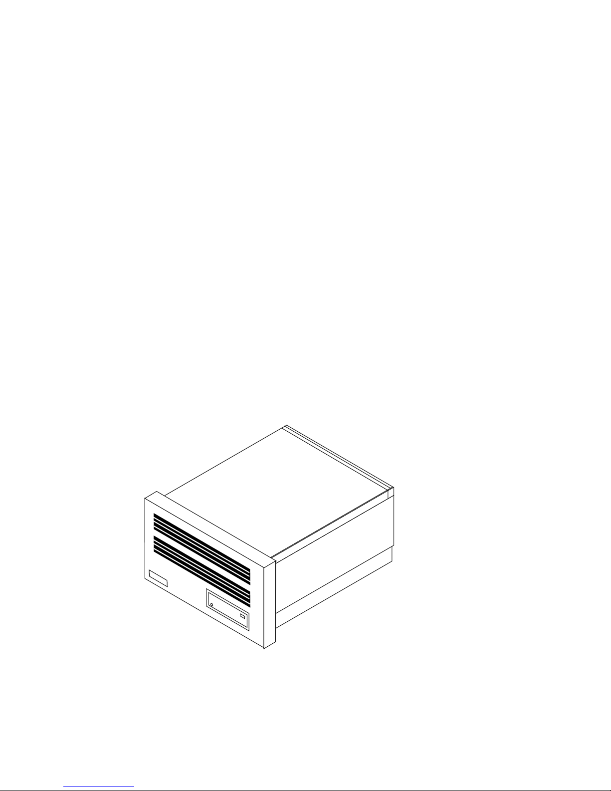
The DEC 3000 Model 400S/600S/700S AXP Rackmount Server
(see Figure 1–1) is the rackmount version of the DEC 3000
Model 400S/600S/700S AXP Server described in the DEC
3000 Model 400/400S AXP Owner’s Guide or DEC 3000 Model
600/600S/700 AXP Owner’s Guide. The systems are functionally
the same.
The DEC 3000 Model 400S/600S/700S AXP Rackmount Server
is preconfigured as a server. It does not include a graphics
card, and is not shipped with a monitor. The system is shipped
with slide assemblies and a cable management system for rack
installation. Chapter 2 and Chapter 3 provide information for
installing the rackmount server system.
The DEC 3000 Model 400S/600S/700S Rackmount Server 1–1
Chapter Overview
Refer to Chapter 1 in the DEC 3000 Model 400/400S AXP
Owner’s Guide or DEC 3000 Model 600/600S/700 AXP Owner’s
Guide as applicable for information about:
• System features
• Software product descriptions
• Operating systems
• Audio capabilities
• Available options
Figure 1–1 DEC 3000 Model 400S/600S/700S AXP Rackmount
Server System
1–2 The DEC 3000 Model 400S/600S/700S Rackmount Server
MK428-01

Preparing to Install the DEC 3000 Model
400S/600S/700S AXP Rackmount Server
Chapter Overview
2
Introduction
In This Chapter
Before installing the DEC 3000 Model 400S/600S/700S AXP
Rackmount Server, it is necessary to verify the installation site,
and be familiar with the system hardware.
This chapter covers the following topics:
• Verifying the Site Preparation
• Unpacking the Rackmount Server System
• Location of Controls and Indicators
Preparing to Install the DEC 3000 Model 400S/600S/700S AXP Rackmount Server 2–1

Verifying the Installation Site
Verifying the Installation Site
Considerations
Review your system warranty. It may require that
a Digital service representative install your system
to prevent damage to equipment or software.
Before installing the rackmount server system, make sure:
• All cables that you plan to connect to the rackmount server
are in place and clearly labeled:
Terminal data cables
Telephone cables
Network cables
Caution
• The specifications and conditions listed in Appendix A
are met. For additional information about planning and
preparing the installation site for a computer network
or free-standing system, refer to the Site Environmental
Preparation Guide (EK-CSEPG-MA) (not shipped with the
system).
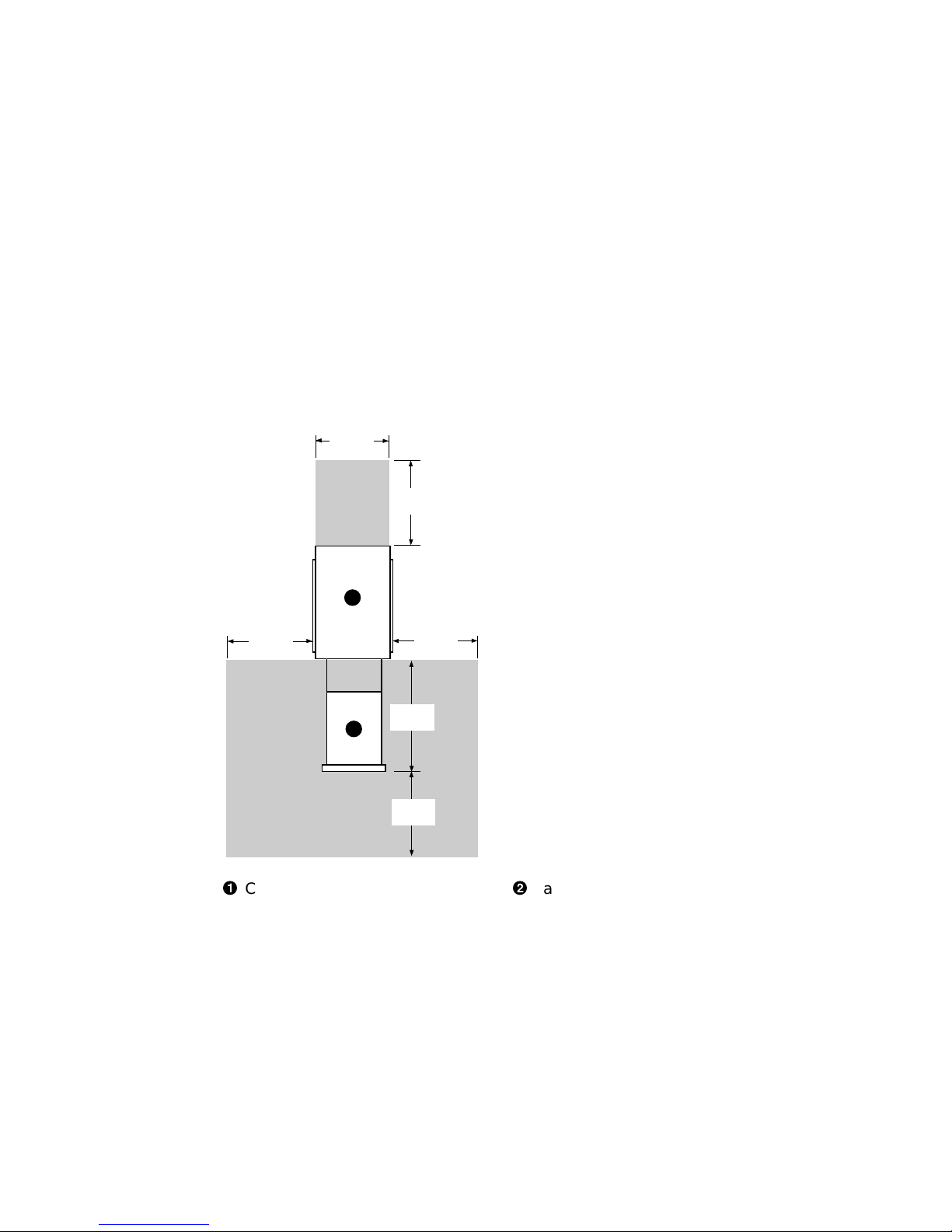
• The system is located in an area that provides sufficient
clearance for ventilation and servicing. Figure 2–1 shows the
clearance required around the system.
2–2 Preparing to Install the DEC 3000 Model 400S/600S/700S AXP Rackmount Server

Verifying the Installation Site
Caution
Do not impede airflow by obstructing the front and
rear of the unit. Exceeding internal thermal limits
can affect system reliability/availability.
Warning
The system weighs 34 kg (75 lbs). To prevent
personal injury and equipment damage, ensure
that the system is contained in an enclosure that
can be stabilized when the system is pulled out on
its slides.
Preparing to Install the DEC 3000 Model 400S/600S/700S AXP Rackmount Server 2–3
Verifying the Installation Site
Figure 2–1 System Clearance Requirements
48.3 cm
(19 in)
1
61 cm
(24 in)
61 cm
(24 in)
!
Cabinet or rack
61 cm
(24 in)
68.6 cm
2
(27 in)
61 cm
(24 in)
MK428-31
"
Rackmount server
2–4 Preparing to Install the DEC 3000 Model 400S/600S/700S AXP Rackmount Server

Unpacking the Rackmount Server System
Unpacking the Rackmount Server System
Checking the
Shipment
Save all packing materials in case you need to
return the system for service or reship the system.
Before installing the system, see Figure 2–2 and check the
packing list to ensure that all items listed have been received.
Your shipment may include several cartons. One carton contains
the system, hardware documentation, software documentation,
system software, diagnostic software, and software licenses.
Depending on your order, your shipment may also include some
of the following devices:
• Terminals
Note
• Printers
• Modems
• Options
Warning
The DEC 3000 Model 400S/600S/700S AXP
Rackmount Server weighs 34 kg (75 lbs). Digital
recommends that at least two people remove it
from the shipping box, as indicated on the packing
carton.
Preparing to Install the DEC 3000 Model 400S/600S/700S AXP Rackmount Server 2–5
Unpacking the Rackmount Server System
If Parts Are
Missing
Screwdriver
and Antistatic
Wrist Strap
Terminator
Connectors
Rackmount
Server
Components
and Parts
If any parts are missing or damaged, contact your delivery agent
immediately, and contact your Digital sales representative.
The Phillips screwdriver, flat blade screwdriver, and antistatic
wrist strap included in the shipment are for use when adding
options or performing removal and installation procedures.
Save the terminator connectors included in the accessory kit in
a safe place. Only the Ethernet loopback connector is needed
during system installation.
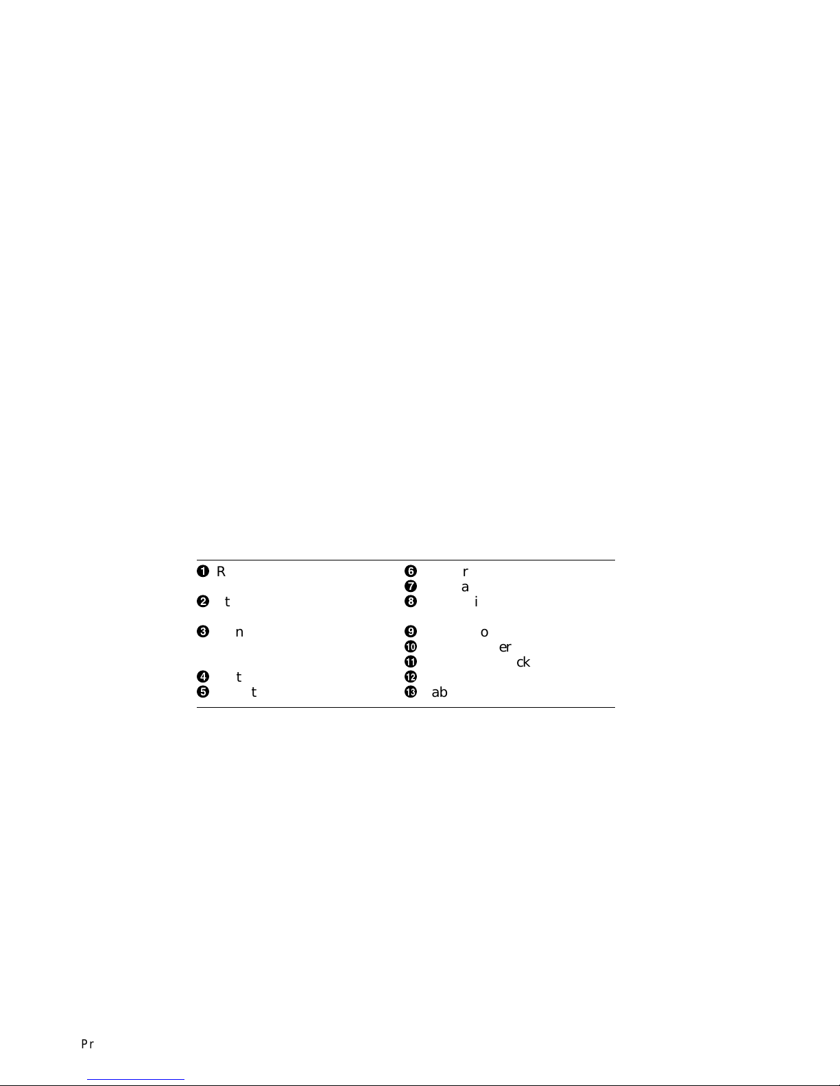
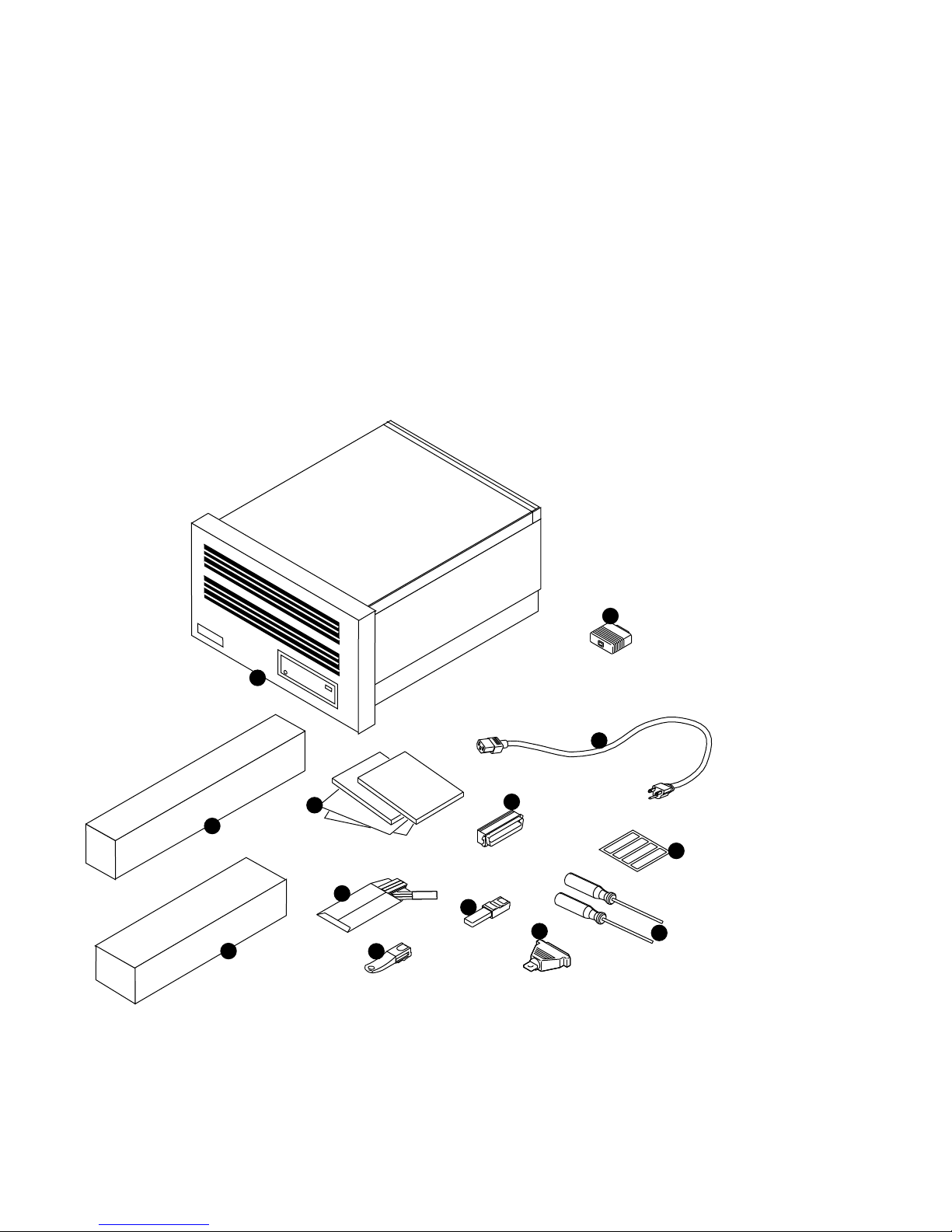
Table 2–1 lists the shipping contents shown in Figure 2–2.
Table 2–1 Shipping Contents
!
Rackmount server (shown
with front bezel attached)
"
Ethernet loopback
connector
#
Owner’s guides,
options guide,
other documentation
$
System power cord
%
SCSI terminator
&
Network label
'
Antistatic wrist strap
(
Screwdrivers (one Phillips,
one flat blade)
)
Printer port terminator
+>
10BASE-T terminator
+?
Modem loopback connector
+@
Pair of slides
+A
Cable carrier
2–6 Preparing to Install the DEC 3000 Model 400S/600S/700S AXP Rackmount Server
Unpacking the Rackmount Server System
Figure 2–2 Rackmount Server Components and Parts
1
2
4
10
5
6
11
8
MK428-40
12
13
3
7
9
Preparing to Install the DEC 3000 Model 400S/600S/700S AXP Rackmount Server 2–7

Unpacking the Rackmount Server System
Mounting
Hardware
Table 2–2 lists the mounting hardware included with the system
for installation into a RETMA standard 19-inch rack.
Table 2–2 Mounting Hardware
Description Part Number Quantity
Slide assembly 12-32764-05 1 pair
Cable carrier 12-26281-01 1
2–8 Preparing to Install the DEC 3000 Model 400S/600S/700S AXP Rackmount Server

A Closer Look at the Rackmount Server System
A Closer Look at the Rackmount Server System
Rear of the
Rackmount
Server System
The rackmount server has the same ports, switches, and
indicators as on the desktop version of the server described
in Chapter 2 of the DEC 3000 Model 400/400S AXP Owner’s
Guide or DEC 3000 Model 600/600S/700 AXP Owner’s Guide.
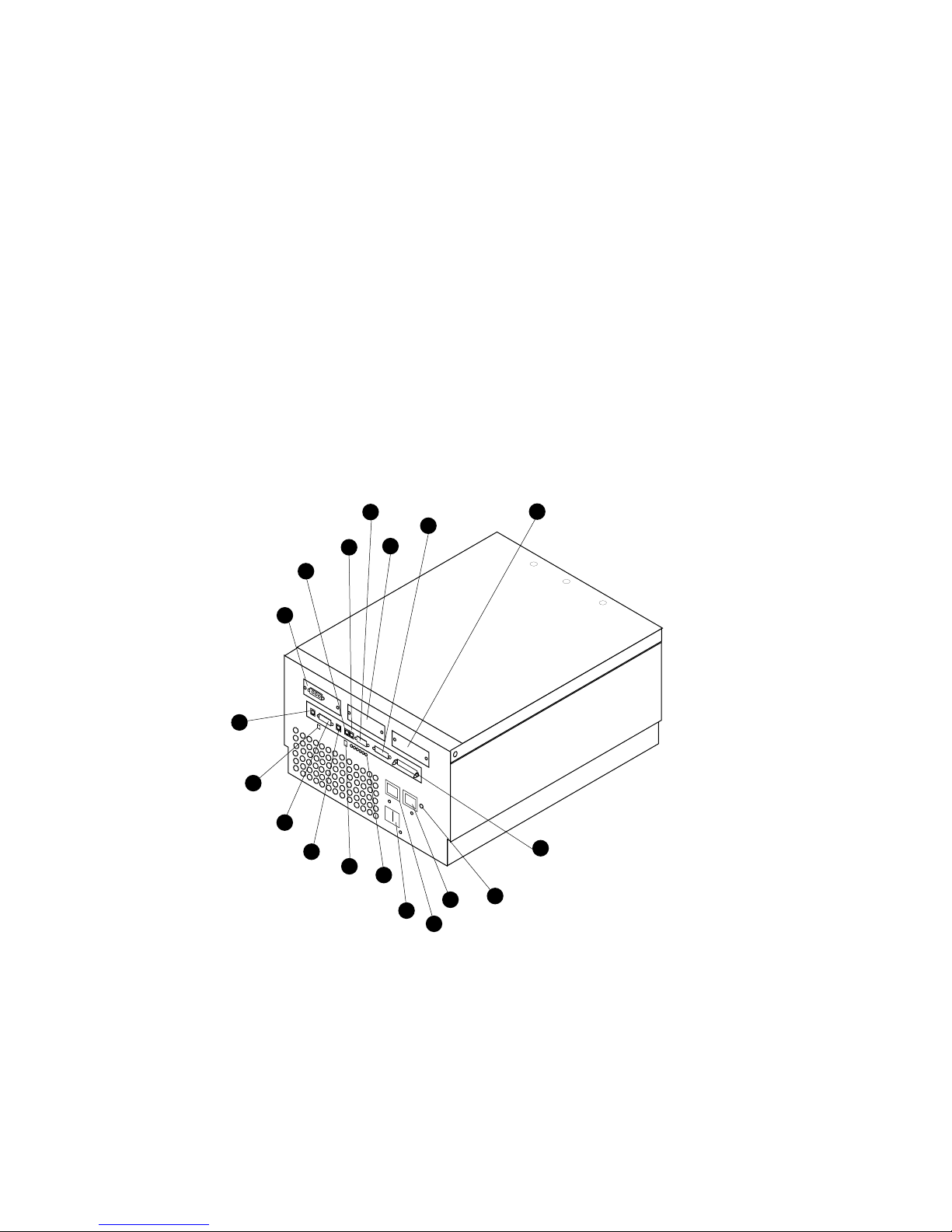
Figure 2–3 shows the location of the ports, switches and
indicators at the rear of the rackmount server system; Table 2–3
describes their functions.
Preparing to Install the DEC 3000 Model 400S/600S/700S AXP Rackmount Server 2–9
A Closer Look at the Rackmount Server System
Figure 2–3 Rear View of Rackmount Server System
14
12
10
1
6
7
8
9
11
13
15
2
18
17
5
4
3
16
MK428-17
2–10 Preparing to Install the DEC 3000 Model 400S/600S/700S AXP Rackmount Server
A Closer Look at the Rackmount Server System
Table 2–3 Rear Ports, Switches and Indicators
Index Feature Function
!
"
#
$
%
&
'
(
)
+>
+?
+@
+A
+B
+C
+D
+E
+F
TURBOchannel slot 0 For TURBOchannel options
TURBOchannel slot 1 For TURBOchannel options
TURBOchannel slot 2 For TURBOchannel options
Auxiliary power
1
socket
To connect a monitor power cord so the monitor does not
require a connection to a separate power outlet
System power socket To connect the rackmount server system power cord
10BASE-T port To connect a 10BASE-T Ethernet network cable
Halt button To place the system in console mode
AUI Ethernet
network port
To connect an AUI Ethernet network cable (sometimes
referred to as standard or Thickwire Ethernet)
ISDN port Currently not in use
Audio port To connect the audio input and output adapter
Alternate console
switch
Alternate console
/printer port
Diagnostic display
Toggle switch to redirect console output from a monitor (switch
up) to an alternate console such as a terminal (switch down)
To connect either a terminal as an alternate console, or a
printer
Used for diagnostic testing purposes
lights
Keyboard/mouse
1
port
Synchronous
/asynchronous
To connect the keyboard/mouse assembly unit
To connect a communications device such as a printer, plotter,
modem, or console terminal
communications port
SCSI port To connect Small Computer System Interface (SCSI)
peripheral devices
Power On/Off switch To turn the system unit power ON | and OFF (O)
Power On/Off
When lit, indicates that the rackmount server is on
indicator
1
Not supported in the DEC 3000 Model 400S/600S/700S AXP Rackmount Server
Preparing to Install the DEC 3000 Model 400S/600S/700S AXP Rackmount Server 2–11
A Closer Look at the Rackmount Server System
Rackmount
Server System
Symbols
Front of the
Rackmount
Server System
The rear of the rackmount server has symbols next to most of
the connectors and ports. These symbols are defined in Chapter
2oftheDEC 3000 Model 400/400S AXP Owner’s Guide or DEC
3000 Model 600/600S/700 AXP Owner’s Guide as applicable.
These definitions also apply to the rackmount server.
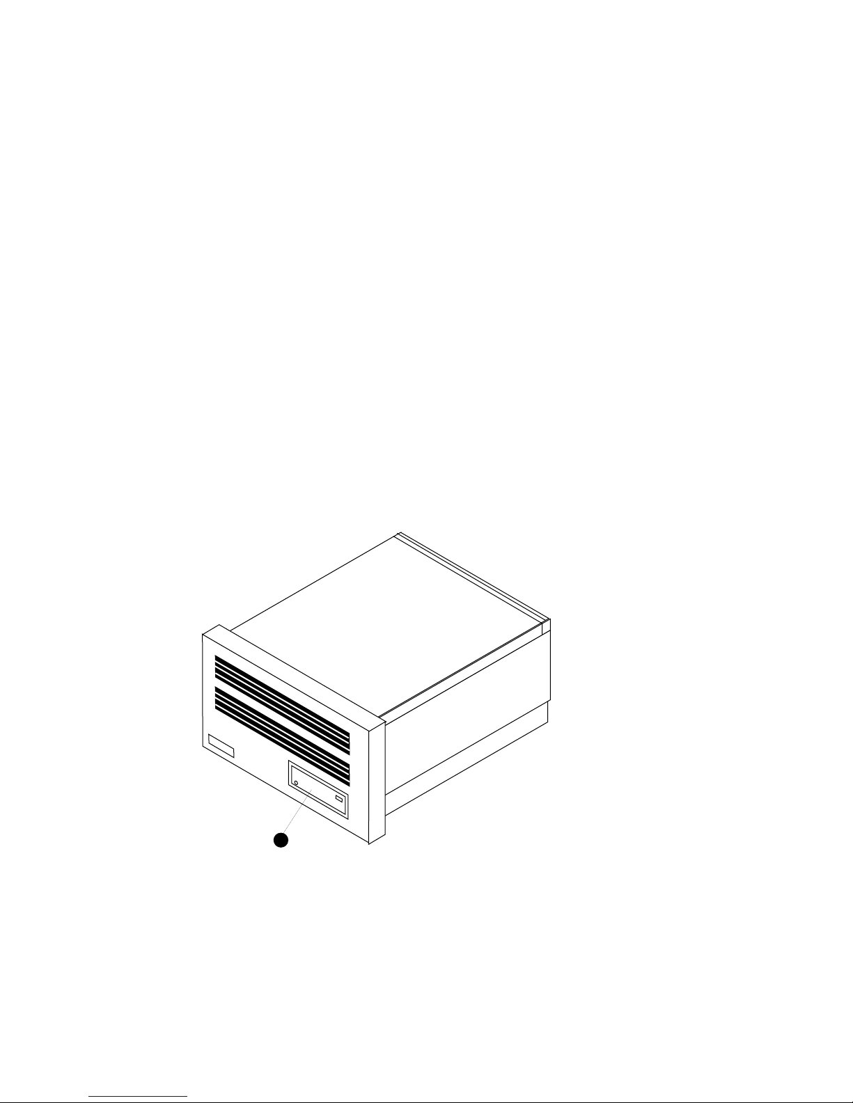
Figure 2–4 shows the front of the system. Table 2–4 describes
the items shown.
Figure 2–4 Front View of the Rackmount Server System
1
2–12 Preparing to Install the DEC 3000 Model 400S/600S/700S AXP Rackmount Server
MK428-13
A Closer Look at the Rackmount Server System
Table 2–4 Front Controls and Indicators
Index Feature Function
!
Optional
removable
media device
slot
Slot for inserting: an RRD43 compact
disc drive, an RX26 floppy disk drive,
a TLZ06 drive, a TKZ10 drive, or a
TZ30 drive.
Preparing to Install the DEC 3000 Model 400S/600S/700S AXP Rackmount Server 2–13
 Loading...