

Page 1

DEC3000Model500/500SAXP
Owner’sGuide
Order Number: EK–FLAMI–OG. C01
Digital Equipment Corporation, Maynard, Massachusetts
Page 2

Second Printing, April, 1993
© Digital Equipment Corporation 1993.
All Rights Reserved.
No responsibility is assumed for the use or reliability of software on equipment
that is not supplied by Digital Equipment Corporation or its affiliated
companies.
The information in this document is subject to change without notice and
should not be construed as a commitment by Digital Equipment Corporation.
Digital Equipment Corporation assumes no responsibility for any errors that
may appear in this document.
The postpaid Reader’s Comments forms at the end of this document request
your critical evaluation to assist in preparing future documentation.
The following are trademarks of Digital Equipment Corporation: Alpha
AXP, AXP, Bookreader, DEC, DECaudio, DECchip 21064, DECconnect, DEC
GKS, DECnet, DEC PHIGS, DECsound, DECwindows, DECwindows Motif,
DECwindows Mail, DECwrite, DELNI, DESTA, OpenVMS, OpenVMS AXP,
RX26, ScriptPrinter, ThinWire, TURBOchannel, ULTRIX, XMedia, VAX, VAX
DOCUMENT, VAXcluster, VAXstation, the AXP logo, and the DIGITAL logo.
CD is a trademark of Data General Corporation.
Open Software Foundation is a trademark of Open Software Foundation, Inc.
Motif, OSF, OSF/1 and OSF/Motif are registered trademarks of Open Software
Foundation, Inc.
ISDN is a registered trademark of Fujitsu Network Switching of America
Mylar is a registered trademark of E.I. DuPont de Nemours & Company, Inc.
UNIX is a registered trademark of UNIX System Laboratories, Inc.
FCC NOTICE: This equipment has been tested and found to comply with
the limits for a Class A digital device, pursuant to Part 15 of the FCC Rules.
These limits are designed to provide reasonable protection against harmful
interference when the equipment is operated in a commercial environment.
This equipment generates, uses, and can radiate radio frequency energy and, if
not installed and used in accordance with the instruction manual, may cause
harmful interference to radio communications. Operation of this equipment in
a residential area is likely to cause harmful interference, in which case users
will be required to correct the interference at their own expense.
S2231
This document is available on CD–ROM.
This document was prepared using VAX DOCUMENT, Version 2.1.
Page 3

Contents
Preface ..................................................... xv
Part I Basic Operations
1 Introduction to Your System
Chapter Overview . ................................... 1–1
System Configurations ................................ 1–2
An Overview of the DEC 3000 Model 500/500S AXP System . . . 1–3
Operating Systems ................................... 1–6
Software Product Descriptions (SPD) . . ................... 1–8
Graphics Capabilities ................................. 1–8
Integrated Services Digital Network (ISDN) ................ 1–11
Audio Capabilities . ................................... 1–12
Available Options . ................................... 1–13
System Enclosures ................................... 1–15
2 Preparing to Install the System
Chapter Overview . ................................... 2–1
Choosing a Location .................................. 2–2
Customizing Your Work Area ........................... 2–4
Moving Your System .................................. 2–6
Unpacking a Workstation System ........................ 2–8
Unpacking a Server System . ........................... 2–11
A Closer Look at a Pedestal System . . . ................... 2–14
A Closer Look at a Rackmount System . ................... 2–18
System Unit Symbols ................................. 2–22
Where to Go Next . ................................... 2–23
iii
Page 4

3 Installing a Workstation System
Chapter Overview . ................................... 3–1
Before You Begin . . ................................... 3–2
Task Overview . . . ................................... 3–3
Connecting the DEC 3000 Model 500 AXP Workstation ....... 3–5
System Unit Cover Lock ............................... 3–17
Checking Your Installation . . ........................... 3–20
Where to Go Next . ................................... 3–21
4 Installing a Server System
Chapter Overview . ................................... 4–1
Before You Begin . . ................................... 4–2
Task Overview . . . ................................... 4–3
Connecting the DEC 3000 Model 500S AXP Server .......... 4–4
System Unit Cover Lock ............................... 4–10
Checking Your Installation . . ........................... 4–13
Where to Go Next . ................................... 4–14
5 Connecting the System to a Network
Chapter Overview . ................................... 5–1
Before You Begin . . ................................... 5–2
Connecting to an AUI Ethernet Network .................. 5–4
Connecting to a 10BASE-T Network . . . ................... 5–6
Connecting to a ThinWire Network ....................... 5–8
Setting and Verifying the Network Connection .............. 5–12
Completing the Network Connection . . ................... 5–14
6 Starting Up the System
Chapter Overview . ................................... 6–1
Before You Begin . . ................................... 6–2
Turning On the DEC 3000 Model 500/500S AXP System ...... 6–3
Reviewing the Startup Display .......................... 6–6
Starting a System with Factory-Installed Software .......... 6–8
Loading Operating System Software . . . ................... 6–13
Where to Go Next . ................................... 6–14
iv
Page 5

7 Turning Off the System
Chapter Overview . ................................... 7–1
Before You Begin . . ................................... 7–2
Task Overview . . . ................................... 7–3
Shutting Down the System . . ........................... 7–4
Halting the System ................................... 7–6
8 Maintaining the System
Chapter Overview . ................................... 8–1
Before You Begin . . ................................... 8–2
Maintaining the System Unit and Keyboard ................ 8–2
Cleaning the Monitor ................................. 8–4
Cleaning the Mouse .................................. 8–4
Removing the Front Access Door ........................ 8–6
Part II Advanced Operations
9 Using Console Commands
Chapter Overview . ................................... 9–1
Before You Begin . . ................................... 9–2
Modes of System Operation . ........................... 9–3
Console Mode User Interface ........................... 9–4
Console Commands ................................... 9–6
The boot Command ................................... 9–8
The continue Command ............................... 9–11
The halt Command ................................... 9–11
The help Command ................................... 9–12
The help advanced Command ........................... 9–13
The set or setenv Command . ........................... 9–14
The show or printenv Command ......................... 9–15
The test Command ................................... 9–16
10 Changing Environment Variables
Chapter Overview . ................................... 10–1
Before You Begin . . ................................... 10–2
Available Environment Variables ........................ 10–2
Displaying Current Environment Variables ................ 10–4
Changing the Default Startup Action (auto_action) .......... 10–5
Changing the Default Boot Device (bootdef_dev) . . . .......... 10–7
v
Page 6

Changing the Default Diagnostic Startup Mode (diag_quick) . . . 10–9
Changing the Default Keyboard Language (language) ........ 10–10
11 Using the Password Security Feature
Chapter Overview . ................................... 11–1
Before You Can Use This Chapter ....................... 11–2
Before You Begin . . ................................... 11–3
Task Overview . . . ................................... 11–5
Entering a Password .................................. 11–5
Enabling System Security . . . ........................... 11–7
Forgetting the Password ............................... 11–8
Disabling or Changing the Password . . ................... 11–9
12 Using an Alternate Console
Chapter Overview . ................................... 12–1
Before You Begin . . ................................... 12–2
Using the Alternate Console Feature . . ................... 12–3
Part III Handling Problems
13 Identifying a Problem
Chapter Overview . ................................... 13–1
Before You Begin . . ................................... 13–2
Task Overview . . . ................................... 13–3
Determining Type of Problem ........................... 13–4
Startup Problems . ................................... 13–6
Interpreting the show Command Display .................. 13–12
Display Problems . ................................... 13–21
Daily Operations Problems . . ........................... 13–24
SCSI Device Problems ................................. 13–25
Network Problems ................................... 13–28
Where to Go Next . ................................... 13–29
vi
Page 7

14 Running Diagnostic Tests
Chapter Overview . ................................... 14–1
Before You Begin . . ................................... 14–2
Task Overview . . . ................................... 14–3
Running Diagnostic Tests . . . ........................... 14–4
Recording the Diagnostic Display Light Pattern . . . .......... 14–8
Reporting Problems to Digital Services . ................... 14–10
Handling Problems Worksheet .......................... 14–16
Part IV Appendixes
A Hardware Specifications
Appendix Overview ................................... A–1
System Specifications ................................. A–2
B Port Pin-outs
Appendix Overview ................................... B–1
Alternate Console/Printer Port .......................... B–2
Synchronous/Asynchronous Communications Port . .......... B–3
External SCSI Port ................................... B–5
Keyboard/Mouse or Tablet Port .......................... B–7
AUI Ethernet Port ................................... B–8
ISDN Port .......................................... B–10
10BASE-T Port . . . ................................... B–11
Audio Port .......................................... B–12
C European Economic Community (EEC) Considerations
Appendix Overview ................................... C–1
EEC Installation Instructions for Nonshielded Cables ........ C–2
D Associated Documents
Appendix Overview ................................... D–1
Associated Printed Documents .......................... D–2
OpenVMS AXP Documentation .......................... D–5
DEC OSF/1 AXP Documentation ........................ D–6
vii
Page 8

E Special Information for PTT Network Users
Appendix Overview ................................... E–1
Service Categories . ................................... E–2
Host Power Rating ................................... E–3
Module Isolation . . ................................... E–4
Safety Warnings for UK Installations Only ................. E–5
Cable Approval . . . ................................... E–7
Supported Cables . ................................... E–8
Equipment Between the Approved Module and a Digital Circuit
(PTT) . . ........................................... E–9
Glossary
Index
Figures
1–1 The DEC 3000 Model 500 AXP Workstation . . . .......... 1–3
1–2 The DEC 3000 Model 500S AXP Server ................. 1–4
1–3 Audio Ports on the DEC 3000 Model 500/500S AXP ....... 1–12
1–4 DEC 3000 Model 500S AXP server in H9A00-AJ Rack
Enclosure ........................................ 1–16
2–1 Dimensions of System . . . ........................... 2–2
2–2 Positioning Components . . ........................... 2–4
2–3 The DEC 3000 Model 500/500S AXP System Handle ...... 2–6
2–4 Lifting the DEC 3000 Model 500/500S AXP .............. 2–7
2–5 Required Workstation Components and Parts . . .......... 2–9
2–6 Components and Parts to Save ....................... 2–10
2–7 Required Server Components and Parts ................ 2–12
2–8 Components and Parts to Save ....................... 2–13
2–9 Back of System Unit ............................... 2–14
2–10 Front of System Unit ............................... 2–16
2–11 Back of System Unit ............................... 2–18
2–12 Front of System Unit ............................... 2–20
3–1 Parts Needed to Install Your Workstation ............... 3–3
3–2 Attaching the Ethernet Loopback Connector . . . .......... 3–5
3–3 Connecting the Keyboard/Mouse Extension Cable ......... 3–6
viii
Page 9

3–4 Connecting the Keyboard and Mouse to the Keyboard/mouse
Extension Cable ................................... 3–7
3–5 Connecting the Universal Strain Relief Strap . . .......... 3–9
3–6 Connecting the Monitor Video Cable ................... 3–12
3–7 Factory-Installed Software Sticker . . ................... 3–13
3–8 Connecting the System Power Cord to System. . .......... 3–14
3–9 Checking the Video Refresh Switch . ................... 3–15
3–10 Checking the Alternate Console Switch ................. 3–16
3–11 System Unit Cover Keys . ........................... 3–17
3–12 Locking the System Unit Cover ....................... 3–19
3–13 A Connected Workstation. ........................... 3–20
4–1 Parts Needed to Install Your Server. ................... 4–3
4–2 Connecting the Ethernet Loopback Connector . . .......... 4–5
4–3 Connecting a Terminal to the Server ................... 4–6
4–4 Factory Installed Software Sticker . . ................... 4–7
4–5 Connecting Power Cord to System Unit ................. 4–8
4–6 Checking the Alternate Console Switch ................. 4–9
4–7 System Unit Cover Keys . ........................... 4–10
4–8 Locking the System Unit Cover ....................... 4–12
4–9 A Connected Server ................................ 4–13
5–1 Connecting to an AUI Ethernet Network ................ 5–5
5–2 Connecting a 10BASE-T Network Cable ................ 5–7
5–3 Connecting the AUI Ethernet Cable to the DECXM
Transceiver or a DESTA Unit ........................ 5–9
5–4 Connecting the ThinWire Cables and T-Connector to the
DECXM Transceiver or a DESTA Unit ................. 5–10
5–5 Terminating the Ethernet Connection .................. 5–11
6–1 Turning On the DEC 3000 Model 500/500S AXP System . . . . 6–5
6–2 Startup Display ................................... 6–6
6–3 OpenVMS AXP Initial Startup Display ................. 6–9
6–4 OpenVMS AXP DECwindows Motif Start Session Screen . . . 6–10
6–5 DEC OSF/1 AXP Initial Startup Display ................ 6–11
6–6 DEC OSF/1 AXP DECwindows Motif Start Session
Screen .......................................... 6–12
7–1 Turning Off the System Unit ........................ 7–5
7–2 Pressing the Halt Button . ........................... 7–7
7–3 System Halt Message ............................... 7–8
ix
Page 10

8–1 Removing/Replacing the Mouse Cover Plate . . . .......... 8–5
8–2 Removing the Front Access Door . . . ................... 8–7
10–1 The show device Display . ........................... 10–8
12–1 Attaching a Device to the
Alternate Console/Printer Port........................ 12–4
12–2 Changing the Alternate Console Switch ................. 12–5
13–1 Power Indicator Light . . . ........................... 13–7
13–2 Startup Display with Error .......................... 13–9
13–3 Configuration Display with Error. . . ................... 13–13
13–4 The show device Display . ........................... 13–15
13–5 The show error Display . . ........................... 13–19
13–6 The show memory Display .......................... 13–20
14–1 SCC Diagnostic Test Display ......................... 14–5
14–2 SCC Test Display with Error ......................... 14–6
14–3 Initializing Your System. . ........................... 14–7
14–4 Initializing the System with the SCC Test ............... 14–7
14–5 Position of Diagnostic Display Lights................... 14–8
14–6 Console Mode Diagnostic Lights . . . ................... 14–9
14–7 Serial and Model Numbers .......................... 14–11
14–8 Connecting the 10BASE-T Loopback Connector . .......... 14–13
14–9 Connecting the Alternate Console/Printer Loopback
Connector ........................................ 14–14
14–10 Connecting the Modem Loopback Connector . . . .......... 14–15
B–1 Alternate Console/Printer Port........................ B–2
B–2 Synchronous/Asynchronous Communications Port......... B–3
B–3 External SCSI Port ................................ B–5
B–4 Keyboard/Mouse or Tablet Port ....................... B–7
B–5 AUI Ethernet Port ................................. B–8
B–6 ISDN Port ....................................... B–10
B–7 10BASE-T Port ................................... B–11
B–8 Audio Port ....................................... B–12
C–1 Connecting a Pigtail Grounding Wire .................. C–3
E–1 Front View ....................................... E–6
E–2 Connector Pin Layout . . . ........................... E–7
x
Page 11

Tables
1 Parts Description .................................. xv
1–1 Graphics Capabilities for OpenVMS AXP ............... 1–9
1–2 Graphics Capabilities for DEC OSF/1 AXP .............. 1–10
1–3 Setting Up Multiple Graphics Devices .................. 1–10
2–1 Positioning Your System Components .................. 2–5
2–2 Back of the System Unit . ........................... 2–15
2–3 Front of the System Unit . ........................... 2–17
2–4 Back of the System Unit . ........................... 2–19
2–5 Front of the System Unit . ........................... 2–21
2–6 Where to Go Next ................................. 2–23
3–1 Steps to Install Your DEC 3000 Model 500 AXP
Workstation . . . ................................... 3–4
3–2 Making Monitor Connectors .......................... 3–10
3–3 Connecting the Monitor Cords ........................ 3–11
3–4 Where to Go Next ................................. 3–21
4–1 Steps to Install Your DEC 3000 Model 500S AXP Server . . . . 4–4
4–2 Where to Go Next ................................. 4–14
5–1 Required Network Cables ........................... 5–3
5–2 Steps for Connecting an AUI Ethernet Network .......... 5–4
5–3 Steps for Connecting a ThinWire Ethernet Network ....... 5–8
5–4 DECXM and DESTA Documentation ................... 5–11
5–5 Network Settings .................................. 5–12
6–1 Steps for Starting a Workstation . . ................... 6–4
6–2 Steps for Starting a Server .......................... 6–4
6–3 Startup Display Information ......................... 6–7
6–4 Factory-Installed Software Documentation .............. 6–8
6–5 Start the Operating System .......................... 6–13
6–6 Where to Go Next ................................. 6–14
7–1 Current System Status . . ........................... 7–2
7–2 Steps to Shutting Down Your System .................. 7–3
7–3 Operating System Shutdown Procedure ................. 7–4
7–4 Halting the Operating Systems ....................... 7–6
8–1 Steps for Cleaning the Mouse ........................ 8–5
8–2 Steps to Remove the Front Access Door ................. 8–6
9–1 Supported Keys and Control Characters ................ 9–5
xi
Page 12

9–2 Advanced Console Commands ........................ 9–6
9–3 Basic Console Commands. ........................... 9–7
9–4 Boot Command Parameters/Qualifiers .................. 9–8
9–5 Device Naming Conventions ......................... 9–9
9–6 Diagnostic Tests ................................... 9–16
10–1 Environment Variables. . . ........................... 10–3
10–2 Parameters for Setting Startup Action.................. 10–5
10–3 Device Naming Conventions ......................... 10–7
11–1 Console Command Access ........................... 11–4
11–2 Steps to Making the System Secure . ................... 11–5
11–3 Entering a Password ............................... 11–6
11–4 Enabling System Security ........................... 11–7
11–5 Steps to Access System . . ........................... 11–8
11–6 Entering a Password ............................... 11–9
12–1 Current System Status . . ........................... 12–2
12–2 Alternate Console/Printer Port Parameters .............. 12–2
12–3 Using the Alternate Console ......................... 12–3
13–1 How to Identify a Problem ........................... 13–2
13–2 Steps to Resolving Problems ......................... 13–3
13–3 Type of Problem ................................... 13–5
13–4 Power Indicator Light Failure ........................ 13–6
13–5 Missing Startup Display . ........................... 13–8
13–6 Startup Error Codes................................ 13–10
13–7 Startup Without Booting . ........................... 13–11
13–8 Information Provided by the show Console Commands . . . . . 13–12
13–9 The show config Display Described . ................... 13–14
13–10 The show device Display Described . ................... 13–16
13–11 System Device Errors............................... 13–18
13–12 Error Message Elements . ........................... 13–19
13–13 Monitor Display Problems ........................... 13–22
13–14 Monitor Display Problems ........................... 13–23
13–15 Mouse Problems ................................... 13–24
13–16 Keyboard Problems ................................ 13–24
13–17 Installed Disk Drive Problems ........................ 13–25
13–18 Installed Software Problems ......................... 13–26
13–19 Software on Diskette Problems ....................... 13–27
13–20 Resolving NI Errors ............................... 13–28
xii
Page 13

13–21 Problems When Booting from the Network .............. 13–29
14–1 Steps to Diagnostic Tests . ........................... 14–3
14–2 Diagnostic Tests ................................... 14–4
14–3 Telephone Numbers of Digital Support Centers . .......... 14–12
A–1 System Unit Dimensions: Pedestal . ................... A–2
A–2 System Unit Dimensions: Rackmount .................. A–2
A–3 System Electrical Specifications ....................... A–2
A–4 General System Specifications ....................... A–3
A–5 System Environmental Specifications .................. A–4
B–1 Alternate Console/Printer Port Pin-outs ................. B–2
B–2 Synchronous/Asynchronous Communications Port
Pin-outs ......................................... B–3
B–3 External SCSI Port Pin-outs ......................... B–5
B–4 Keyboard/Mouse or Tablet Port Pin-outs ................ B–7
B–5 AUI Ethernet Port Pin-outs .......................... B–9
B–6 ISDN Port Pin-outs ................................ B–10
B–7 10BASE-T Port Pin-outs . ........................... B–11
B–8 Audio Port Pin-outs ................................ B–12
D–1 Associated Printed Documents ........................ D–2
D–2 Drives .......................................... D–3
D–3 Handbook Series .................................. D–3
D–4 TURBOchannel-Related Documents . ................... D–4
D–5 SCSI Documents .................................. D–4
D–6 General OpenVMS AXP Operating System Documents . . . . . D–5
D–7 DECconnect System ................................ D–6
D–8 User Documentation, QA–MT4AB–GZ .................. D–7
D–9 Server Documentation Kit, QA–MT4AL–GZ . . . .......... D–8
E–1 BABT-Approved Service Specifications for the 54-21147
Module for UK Compliance .......................... E–2
E–2 Module Power . ................................... E–3
E–3 Clearance and Creepage Distances . ................... E–5
E–4 Connector Pin-Outs Described ........................ E–7
E–5 Cables Supported by the 54-21147 Module .............. E–8
xiii
Page 14

Preface
Purpose of
This Guide
Structure of
This Guide
This guide is intended for all users of the DEC 3000 Model 500
/500S AXP system. It describes how to install and operate the
DEC 3000 Model 500 AXP workstation and the DEC 3000 Model
500S AXP server. To install options in the DEC 3000 Model
500/500S AXP system, refer to the DEC 3000 Model 500/500S
AXP Options Guide.
This guide consists of 14 chapters, 5 appendices, a glossary of
technical terms, and an index, and is organized into four parts
as Table 1 describes:
Table 1 Parts Description
Part Title Description
I Basic Operations Chapters in Part I describe
basic operations for using your
workstation or server system,
including installing, turning on, and
maintaining your system. These
chapters are for all DEC 3000
Model 500/500S AXP system users.
(continued on next page)
xv
Page 15

Table 1 (Cont.) Parts Description
Part Title Description
II Advanced
Operations
Chapters in Part II describe
advanced operations for your
system, including use of console
commands and the alternate console
feature. These chapters are for
users who understand advanced
system operations.
III Troubleshooting Chapters in Part III describe what
to do in the event of a system
problem. These chapters are
applicable only if your system is not
working properly or is displaying
error messages.
IV Appendixes The appendixes in Part IV provide
information such as specifications,
and port pinouts.
xvi
Page 16

Conventions
The following conventions are used in this guide:
Convention Description
RZ2x RZ2x refers to the RZ-series fixed disk
drives, including the RZ24L, RZ25, and
RZ26.
Return
A key name in a box indicates that you
press a named key on the keyboard.
Ctrl/x
A sequence such as
Ctrl/x
indicates that
you must hold down the key labeled
Ctrl while you press another key.
show config
Lowercase color type in this format
indicates a command that you must
enter exactly as shown. For example:
>>> show config
Return
variable Lowercase color italics indicate a
variable value that you must provide.
For example:
>>> set
variable
Return
CAUTION Cautions provide information to prevent
damage to equipment or software. Read
these carefully.
WARNING Warnings contain information to
prevent personal injury. Read these
carefully.
xvii
Page 17

Task Symbols
i
All of the tasks described in this guide have been assigned a
symbol indicating the level of difficulty in completing the task.
The task symbols that appear in the margin next to the task
should be used as a guide to help you decide whether you wish to
complete the task, or request help.
Different tasks within a category may require different levels
of expertise. For instance, one intermediate task may require
software expertise, while another intermediate task may require
hardware expertise. Check the Before You Begin section at the
beginning of most chapters, for the specific kind of experience
required to complete a task. This section will be identified by the
information icon, defined below.
Information
This section contains important background information that
will help you to perform the tasks listed and to operate your
DEC 3000 Model 500/500S AXP correctly.
Task
Categories
Task Symbols
on Bookmark
The tasks fall into four categories indicated by four symbols:
Basic Task
This task does not require any specific experience to complete.
Intermediate Task
Some specific experience is required to complete this task.
Advanced Task
Specific experience is highly desirable to complete this task.
The task symbol explanations provided here are also printed
on the bookmark provided with this guide. You can use the
bookmark for reference while using this manual.
xviii
Page 18

PartI
Basic Operations
Part I provides an overview of the DEC 3000 Model 500/500S
AXP system and its configurations. It also describes how to
install the system and how to perform basic operations. This
part includes the following chapters:
Chapter Title
1 Introduction to Your System
2 Preparing to Install the System
3 Installing a Workstation System
4 Installing a Server System
5 Connecting the System to a Network
6 Starting Up the System
7 Turning Off the System
8 Maintaining the System
Page 19

Chapter Overview
1
Introduction to Your System
Introduction
In This Chapter
Congratulations on choosing a DEC 3000 Model 500 AXP
workstation or DEC 3000 Model 500S AXP server. These highperformance, deskside or rackmount systems use Digital’s
DECchip 21064 RISC processor, part of the Alpha AXP
architecture, making them the most powerful low-end systems
ever designed.
The DEC 3000 Model 500/500S AXP system is based on the
Digital Alpha AXP architecture, providing all the advantages of
a 64-bit computing environment.
This chapter covers the following topics:
• System Configurations
• An Overview of the DEC 3000 Model 500/500S AXP System
• Operating Systems
• Software Product Descriptions (SPD)
• Graphics Capabilities
• Integrated Services Digital Network (ISDN)
• Audio Capabilities
• Available Options
• System Enclosures
Introduction to Your System 1–1
Page 20

System Configurations
System Configurations
Two System
Configurations
Workstation
Configuration
Server
Configuration
Your DEC 3000 Model 500/500S AXP system can be configured
as a workstation or as a server system. This guide describes how
to install and set up both configurations.
Your DEC 3000 Model 500 AXP workstation includes 2D
graphics capabilities integral to the system, and will be shipped
with a monitor, mouse, and keyboard. Chapter 3 describes how
to install a workstation system.
Your DEC 3000 Model 500S AXP server also has 2D graphics
capabilities integral to the system, but is not shipped with a
monitor, mouse, or keyboard. Chapter 4 describes how to install
a server system.
1–2 Introduction to Your System
Page 21
An Overview of the DEC 3000 Model 500/500S AXP System
An Overview of the DEC 3000 Model 500/500S AXP System
System
Components:
Workstation
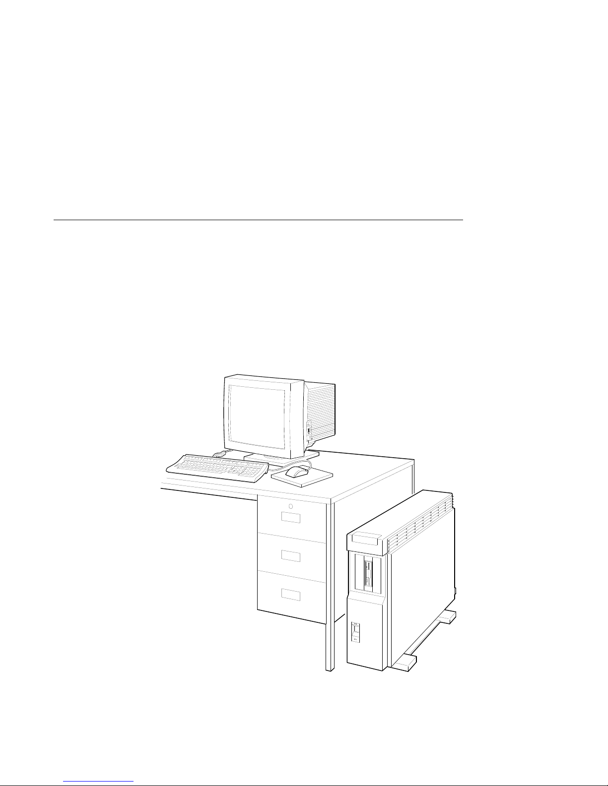
The DEC 3000 Model 500/500S AXP system can be configured
as a workstation or a server. The workstation consists of four
components: a system unit, a monitor, a keyboard, and a mouse.
Figure 1–1 shows a basic workstation configuration.
Figure 1–1 The DEC 3000 Model 500 AXP Workstation
MLO-007581
Introduction to Your System 1–3
Page 22
An Overview of the DEC 3000 Model 500/500S AXP System
System
Components:
Server
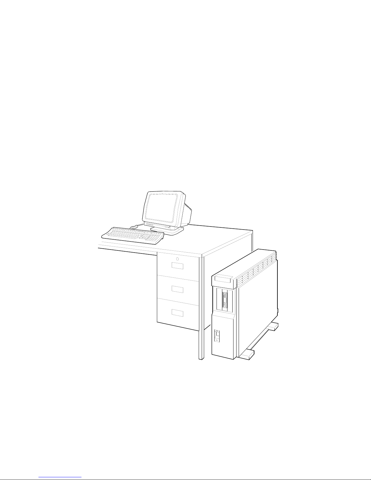
When configured as a server, the DEC 3000 Model 500S
AXP system does not include a monitor, keyboard, or mouse.
Figure 1–2 shows a typical DEC 3000 Model 500S AXP
configuration, with an optional terminal and keyboard.
Figure 1–2 The DEC 3000 Model 500S AXP Server
1–4 Introduction to Your System
MLO-007569
Page 23

An Overview of the DEC 3000 Model 500/500S AXP System
System
Highlights
The DEC 3000 Model 500/500S AXP system provides the
following special features:
This system feature... Provides...
Full 64-bit Alpha RISC
architecture
Up to 256 megabytes of
memory
Accelerated 2D graphics 8-plane, accelerated 2D graphics and
Multi-head graphic support Support for multiple graphic heads.
Internal and external options Increased storage capacity, graphics,
An Attachment Unit
Interface (AUI) Ethernet
port
A 10BASE-T network port Connection to a twisted-pair network
ISDN network ready An industry-standard port for an ISDN
Six TURBOchannel slots Access to high-performance module
Audio technology Built-in telephone-quality audio input
Secure console mode feature Limited access to core console functions
A password security feature Additional system security for
Two supported operating
systems
Double the 32-bit memory address.
Expandable memory using 32- and 64megabyte memory options.
windowing operations.
The number of graphics heads
supported depends on the operating
system.
communications, and other capabilities
to your system.
Connection to an AUI Ethernet
network.
network connection.
interconnect technology that allows a
variety of options, including graphics,
multimedia, communications, and other
third-party options.
and output capabilities.
for added system security.
privileged commands when the system
is in secure console mode.
Support for the OpenVMS AXP and the
DEC OSF/1 AXP operating systems.
Introduction to Your System 1–5
Page 24

Operating Systems
Operating Systems
A Choice of
Operating
Systems
Supported
Operating
Systems
OpenVMS AXP
Operating
System
Features of
OpenVMS AXP
Digital’s Alpha AXP architecture allows you to choose from
various operating systems for use on your DEC 3000 Model
500/500S AXP system. The operating system is the core software
installed on your DEC 3000 Model 500/500S AXP system, which
allows you to install and run applications.
Currently, both of the following operating systems are supported
for use on your DEC 3000 Model 500/500S AXP system:
• OpenVMS AXP
• DEC OSF/1 AXP
These two are the operating systems supported with the first
shipments of the DEC 3000 Model 500/500S AXP system. Other
operating systems may be supported at a later time.
The OpenVMS AXP operating system is a general purpose,
multiuser operating system that can be used in many different
environments for a wide variety of applications.
The OpenVMS AXP operating system promotes ease of use and
improved programming productivity, and it facilitates system
management.
OpenVMS AXP offers a combination of commercial features and
open system benefits, including the following capabilities:
• Integrated networking
• System security
• Distributed computing
• Windowing capabilities
Additionally, OpenVMS AXP supports a large number of
industry standards to facilitate application portability and
interoperability.
1–6 Introduction to Your System
Page 25

Operating Systems
DEC OSF/1
AXP Operating
System
Description
of DEC OSF/1
AXP
DEC OSF/1 AXP
Architecture
DEC OSF/1 AXP is Digital Equipment Corporation’s
implementation of the Open Software Foundation (OSF)
operating system components and Motif graphical user interface
and programming environment.
DEC OSF/1 AXP is compliant with the OSF Application
Environment Specification (AES), which specifies the interface
to support portable applications designed to run on a variety of
hardware platforms.
In addition, the DEC OSF/1 operating system complies with
these standards and industry specifications:
• FIPS 151-1
• POSIX (IEEE Std. 1003.1-1988)
• XPG3 BASE branding
• XTI
• AT&T System V Interface Definition (SVID) Issue 2 (Base
System and Kernel Extensions)
The DEC OSF/1 AXP operating system is an advanced kernel
architecture based on Carnegie Mellon University’s Mach
V2.5 kernel design with components from Berkeley Software
Distribution 4.3 (BSD) and other sources. DEC OSF/1 AXP
provides numerous features to assist application programmers
in developing applications that use shared libraries, multithread
support, and memory mapped files.
To ensure a high level of binary compatibility with the ULTRIX
operating system, the DEC OSF/1 AXP operating system is
compatible with the Berkeley 4.3 programming interfaces.
You May Have
Factory-Installed
Software
If there is a yellow sticker over the system power connector
on your DEC 3000 Model 500/500S AXP system, the operating
system is factory-installed on an internal fixed disk drive, and
you can start it on your system using either the OpenVMS AXP
Factory Installed Software (FIS) procedure, or the DEC OSF/1
AXP Factory-Installed Software (FIS) Startup Procedure.
Chapter 6 describes how to start your system if it has a
factory-installed operating system.
Introduction to Your System 1–7
Page 26

Software Product Descriptions (SPD)
Software Product Descriptions (SPD)
SPD
Description
The Software Product Description (SPD) is the official defining
document for software products licensed by Digital Equipment
Corporation, including third-party products licensed by Digital.
An SPD describes all important functional characteristics of the
software. The terms and conditions under which the corporation
sells and licenses its software products identify SPDs as the
documents that specify Digital’s obligation under software
warranty.
SPDs also describe a software product’s system environment
and identify required and optional hardware and software. All
information contained in the SPD is valid in the international
marketplace.
For more information on the SPD for your operating system,
please contact your Digital sales representative.
Graphics Capabilities
Standard
and Optional
Graphics
All DEC 3000 Model 500/500S AXP systems are shipped with
the HX 2D graphics capabilities integral to the system module.
This provides 8-plane, accelerated 2D graphics and windowing
operations for your system.
Additional graphics and multimedia capabilities are available via
a TURBOchannel graphics module that can be installed in your
system. Digital and third-party suppliers provide a wide variety
of TURBOchannel-based graphics options.
1–8 Introduction to Your System
Page 27

Graphics Capabilities
DEC Open3D
Software
OpenVMS AXP
Graphics
Three dimensional (3D) graphics support is provided by the DEC
Open3D software. Contact your Digital sales representative for
availability of the Open3D software as a layered product for both
the OpenVMS AXP and the DEC OSF/1 AXP operating systems.
If your system is running the OpenVMS AXP operating system,
the TURBOchannel graphics options listed in Table 1–1 are
available.
Table 1–1 Graphics Capabilities for OpenVMS AXP
Graphics
Option Capabilities Provided
HX 8-plane, accelerated 2D graphics and windowing
operations.
1
PXG+
PXGT+
1
1
Requires DEC Open3D software
Configurable 3D graphics: either 8- or 24-plane graphics,
double buffered and optional 24-bit Z-buffer graphics.
The PXG+ option requires DEC Open3D software.
96-plane 3D accelerated graphics: 24-plane frame and
double buffer graphics, 24-bit Z-buffer and additional
24-bit configurable buffer graphics.
3D Applications
for the
OpenVMS AXP
Operating
System
In addition to the hardware three-dimensional (3D) graphics
described in Table 1–1, there are also 3D software applications
available for use on the OpenVMS AXP operating system.
Two applications, DEC PHIGS (Programmer’s Hierarchical
Interactive Graphics System) and DEC GKS (Graphics Kernel
System) can be run as layered products. For more information,
contact your Digital sales representative.
Introduction to Your System 1–9
Page 28

Graphics Capabilities
DEC OSF/1
AXP Graphics
Multiple
Graphic
Devices
If your system is running the DEC OSF/1 AXP operating system,
the TURBOchannel graphics options listed in Table 1–2 are
available.
Table 1–2 Graphics Capabilities for DEC OSF/1 AXP
Graphics
Option Capabilities Provided
HX 8-plane, accelerated 2D graphics and windowing
operations.
TX 24-plane, true-color 2D graphics.
1
PXG+
PXGT+
1
1
Requires DEC Open3D software
Configurable 3D graphics: either 8- or 24-plane graphics,
double buffered and optional 24-bit Z-buffer graphics.
96-plane 3D accelerated graphics: 24-plane frame and
double buffer graphics, 24-bit Z-buffer and additional
24-bit configurable buffer graphics.
Your DEC 3000 Model 500/500S AXP system is capable of
supporting multiple 2D graphics devices. For information about
installing another graphics option in your system, see the DEC
3000 Model 500/500S AXP Options Guide.
Information about setting up your system to use more than one
monitor is provided in the documents listed in Table 1–3.
Table 1–3 Setting Up Multiple Graphics Devices
For this operating
system... See this document...
OpenVMS AXP OpenVMS Alpha Version 1.0 Upgrade and
DEC OSF/1 AXP X Window System Administrator’s Guide,
1–10 Introduction to Your System
Installation Manual
vol. 8, available from O’Reilly and
Associates, Inc.
Page 29

Integrated Services Digital Network (ISDN)
Integrated Services Digital Network (ISDN)
Note: ISDN Not
Yet Available
ISDN
Capabilities
Use of ISDN B
Channels
Though your DEC 3000 Model 500/500S AXP system can provide
ISDN capabilities, they are not yet agency approved or available.
Currently, a plug has been placed in the ISDN port pending
approval of ISDN licenses. Once agency approval of ISDN for
the DEC 3000 Model 500/500S AXP system has been granted,
you will be contacted by your Digital sales representative to
inform you of the ISDN certification. At that point, you must
remove the plug from the ISDN port before connecting the ISDN
network.
The following information explains the ISDN capabilities for
your DEC 3000 Model 500/500S AXP system pending license
approval.
ISDN is a digital telecommunications network, providing
connectivity for voice and data applications.
Your DEC 3000 Model 500/500S AXP system includes an ISDN
Basic Rate S/T interface, which includes:
• two 64 kilobits per second B channels
• one 16 kilobits per second D channel
The B channels can be used for digitized voice and circuitswitched data transmission at up to 64 kilobits per second, or for
packet-switched data transmission.
Use of ISDN D
Channels
The D channel uses a protocol standardized by the International
Telegraph and Telephone Consultative Commiittee (CCITT) for
setting up these connections. The D channel can also be used for
low-speed packet transmission.
Introduction to Your System 1–11
Page 30
Audio Capabilities
Audio Capabilities
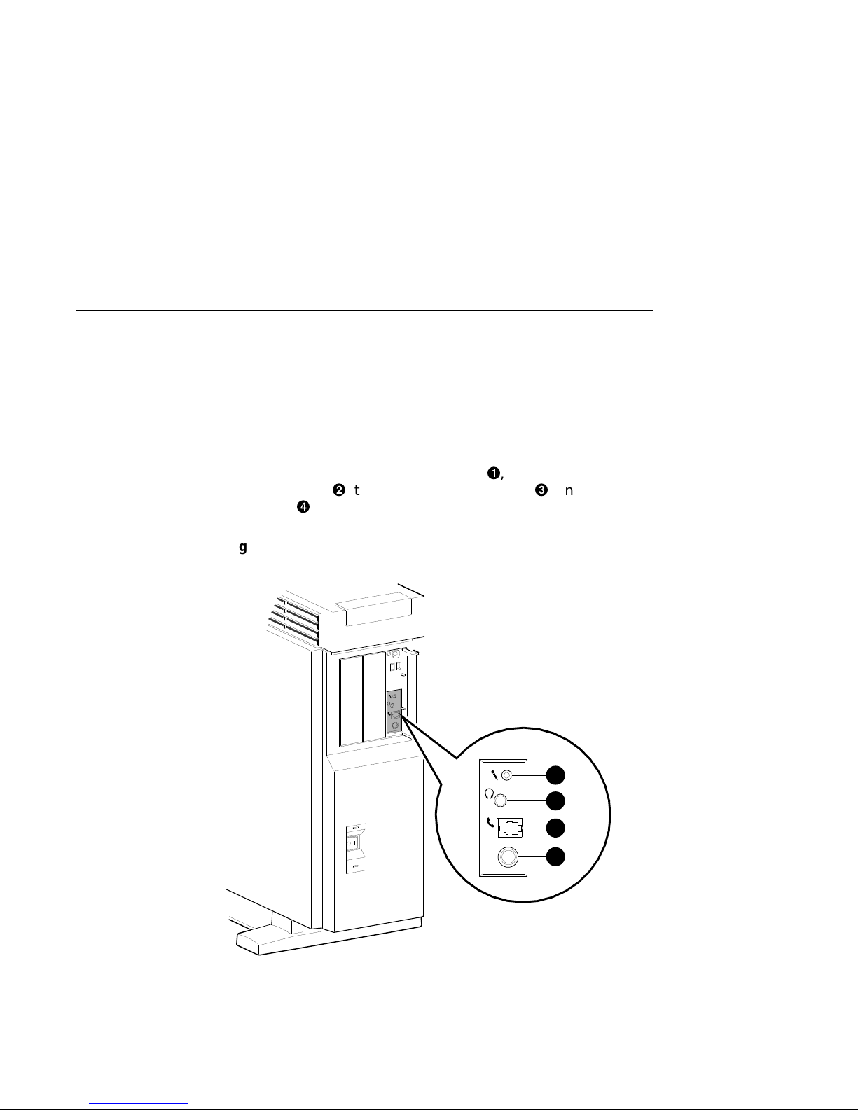
Audio Overview
The DEC 3000 Model 500/500S AXP system features telephonequality audio features, providing audio input and output
capabilities. The audio ports are located on the front of the
system unit, behind the front access door. Figure 1–3 shows the
audio ports: the microphone input jack!, the speaker/
headphone jack", the telephone handset jack#, and the audio
input jack$.
Figure 1–3 Audio Ports on the DEC 3000 Model 500/500S AXP
Line
In
1
2
Port pin-outs for the telephone handset jack on the system unit
are provided in Appendix B.
1–12 Introduction to Your System
3
Line
In
4
MLO-007498
Page 31

Audio Capabilities
DECsound
Application
XMedia
Application
The DECsound application, shipped with your DEC 3000
Model 500 AXP workstation as part of the OpenVMS AXP
DECwindows Motif layered product kit, is an easy-to-use
software application that lets you play back recorded messages,
record audio messages, mail recorded messages, and include
recorded messages in compound documents.
Audio support for DEC OSF/1 AXP systems is provided by
XMedia, Digital’s distributed multimedia software development
environment.
Available Options
Internal
Options
You can install the following hardware options inside the DEC
3000 Model 500/500S AXP system unit:
Option Capabilities Provided
Four RZ2x-series
3½-inch fixed disk
drives
Two 5¼-inch
removable media
devices (RMD)
Up to 256 megabytes
of total memory
Up to six
TURBOchannel
modules
Up to 4 gigabytes of additional storage
capacity.
Additional data storage on any of several
devices: the RX26 diskette drives, the
RRD42 compact disc drive, the TZ30 tape
drive, the TLZ06 tape drive, and the
TZK10 quarter-inch cartridge tape drive.
Increased performance.
A variety of TURBOchannel options,
including 2D and 3D graphics options.
Introduction to Your System 1–13
Page 32

Available Options
TURBOchannel
Options
Installing
Internal
Options
External
Options
There are a total of six TURBOchannel option slots on your
system. Since your 2D graphics capabilities are integral to your
system, you have all six TURBOchannel slots available for other
options.
For more information about adding TURBOchannel and other
internal options to your system, see the DEC 3000 Model 500
/500S AXP Options Guide.
You can add one or more of the following external options to your
system.
• A printer such as a PostScript laser printer.
• A modem
• A puck or stylus tablet
• A BA350 expansion box that can hold the following devices:
• RZ2x-series fixed disk drives
• RRD42 compact disc drive
• TZK10 quarter-inch tape drive
• TLZ06 DAT (digital audio tape) drive
Adding
External
Options
Ordering
Options
1–14 Introduction to Your System
For more information about external options and how to add
them to your DEC 3000 Model 500/500S AXP system, see the
DEC 3000 Model 500/500S AXP Options Guide.
Contact your Digital sales representative for more information
about ordering DEC 3000 Model 500/500S AXP system options.
Page 33

System Enclosures
System Enclosures
Choice of
Enclosures
Choice of Rack
Enclosures
Ordering
Rackmount
Systems
The DEC 3000 Model 500/500S AXP system is supported in one
of two enclosure styles:
• a deskside pedestal enclosure
• a rackmount enclosure
The deskside enclosure requires two people to move it, and can
be positioned by the side of your desk, as shown in Figure 1–1.
Figure 1–4 shows a DEC 3000 Model 500/500S AXP system
unit!installed in an H9A00–AJ rack enclosure. Your Digital
service representative must install the system unit into a rack
enclosure.
You can choose one of two rackmount kits for your DEC 3000
Model 500/500S AXP system:
• IEC–310 (RETMA)-compatible enclosure kit, for industry
standard, third-party rack enclosures
• H9A00–xx kit, for a Digital corporate rack enclosure
Contact your Digital sales representative for more information
about ordering DEC 3000 Model 500S AXP server rackmount
systems.
Introduction to Your System 1–15
Page 34

System Enclosures
Figure 1–4 DEC 3000 Model 500S AXP server in H9A00-AJ
Rack Enclosure
Line
In
1
1–16 Introduction to Your System
MLO-009396
Page 35

Chapter Overview
2
Preparing to Install the System
Introduction
In This Chapter
Before you install your DEC 3000 Model 500/500S AXP system,
you need to prepare your site, and familiarize yourself with your
system hardware.
This chapter covers the following topics:
• Choosing a Location
• Customizing Your Work Area
• Moving Your System
• Unpacking a Workstation System
• Unpacking a Server System
• A Closer Look at a Pedestal System
• A Closer Look at a Rackmount System
• System Unit Symbols
• Where to Go Next
Preparing to Install the System 2–1
Page 36

Choosing a Location
Choosing a Location
Space
Requirements
When choosing a location, consider the system measurements
as shown in Figure 2–1, and allow 7.6 cm (3 inches) ventilation
space between the system unit and the desk.
Figure 2–1 Dimensions of System
7.6 cm
(3 inches)
63 cm
(25 inches)
75 cm
(29 inches)
Monitor
Requirements
When allocating space for your new DEC 3000 Model 500 AXP
workstation, consider also the size of your monitor and the
length of your monitor video cable.
2–2 Preparing to Install the System
32 cm
(13 inches)
MLO-007592
Page 37

Choosing a Location
Location
Requirements
Choose a location for your DEC 3000 Model 500/500S AXP
system that meets the following requirements:
Requirement Explanation
Appropriate dedicated power
source with an isolated
ground
Moderate temperature Room temperature should remain
Relative humidity Relative humidity should range
Ample circulation Provide a minimum of three inches of
Working room Leave enough room on your desktop
Power source must be 110–120 volts
alternating current (VAC) or 220–240
VAC, used solely for system unit and
monitor.
between 15°C and 32°C (59°F and
90°F).
between 30 percent and 70 percent.
clearance all around the workstation.
This allows air to circulate around the
workstation to prevent excess heat
buildup and to keep the system air
vents clean.
for your keyboard, mouse pad, and any
papers and materials that you may
need.
What to Avoid
in a Location
When choosing a location for your workstation, try to avoid the
following hazards:
Hazard How to Avoid
Dust and dirt Position the system unit in a clean, dust-free
Heat and
sunlight
location. Dust and dirt damage system components.
Do not place your DEC 3000 Model 500/500S AXP
system in direct sunlight, close to a heater, or near
a photocopier.
Preparing to Install the System 2–3
Page 38

Customizing Your Work Area
Customizing Your Work Area
Ergonomic
Considerations
Considering the ergonomics of your working environment before
installing your system can help you to perform your job more
effectively once you begin using your DEC 3000 Model 500/500S
AXP system.
Comfort in your workplace can be achieved by making sure that
your chair, monitor, keyboard, and mouse are set at the right
height and distance for you and the work that you are doing, as
shown in Figure 2–2 and explained in Table 2–1.
Figure 2–2 Positioning Components
9
8
7
5
6
4
2–4 Preparing to Install the System
3
2
1
MLO-010354
Page 39

Customizing Your Work Area
Positioning
Components
Table 2–1 explains the numbered elements in Figure 2–2.
Table 2–1 Positioning Your System Components
Adjust your chair so that...
!
Your feet are flat on the floor—use a footrest if
needed.
"
#
Your legs form a right angle to the floor.
The backs of your knees are free from the seat
pan.
$
The body weight rests on the spine with support
at the lower back region.
Adjust your monitor and keyboard so that...
%
Your wrists are straight and supported. Keyboard,
mouse, and mousepad are at elbow height.
&
Your elbows are close to your sides, with your
upper arms perpendicular to the floor.
'
You maintain a neutral neck posture with the top
of the video screen no higher than eye level.
Adjust lighting and monitor so that...
(
Light is directed away from the screen to reduce
glare. Look away to distant objects frequently.
Use the tilt and swivel capabilities of your monitor
to place it in the most comfortable position for
your own use.
)
The screen is at the correct distance for your
vision.
Preparing to Install the System 2–5
Page 40

Moving Your System
Moving Your System
Locate the
Handle
The handle by which to move your system unit is located on
the front, at the top, under the product medallion!, as shown
in Figure 2–3. Grasp this area firmly and pull the system unit
towards you any time you wish to move it. The low-friction feet
on the bottom of the pedestal allow the unit to be moved easily
across the floor.
Figure 2–3 The DEC 3000 Model 500/500S AXP System Handle
1
2–6 Preparing to Install the System
MLO-007579
Page 41

Moving Your System
CAUTION: Two
People to Lift
the System Unit
Two people are needed to lift the DEC 3000 Model 500/500S AXP
system unit, which is quite heavy. The unit is designed to be
lifted using the front handle!and the rear of the system unit
at the top", as shown in Figure 2–4.
Do not attempt to lift the system unit from the bottom, as you
may cause damage to the front or side panels, which are not
designed to hold the weight of the system unit.
Figure 2–4 Lifting the DEC 3000 Model 500/500S AXP
2
1
MLO-009873
Preparing to Install the System 2–7
Page 42

Unpacking a Workstation System
Unpacking a Workstation System
Checking the
Box Contents
If Parts Are
Missing
WARNING:
Two People
Required
Your workstation system arrives in two boxes, one for the system
unit and accessories, the other for the monitor.
Before installing your system, check to see that you have all
of the parts shown in Figure 2–5. The contents shown are for
preconfigured systems. If you did not order a preconfigured
system, check your packing slip to make sure that whatever you
ordered has arrived in your shipment.
If you are missing any parts for your DEC 3000 Model 500
AXP workstation, contact your Digital sales representative
immediately.
The DEC 3000 Model 500 AXP workstation and the monitor
shipped with your system are both quite heavy. Have someone
help you remove these items from the shipping boxes, as
indicated on the packing cartons.
2–8 Preparing to Install the System
Page 43

Unpacking a Workstation System
Parts Required
for Installation
The accessory kit for your system includes many parts, some
of which you do not need during the system installation. See
Figure 2–5 for the parts you need.
Figure 2–5 Required Workstation Components and Parts
Monitor
Video Cable
Monitor Power Cord
System Unit
Keyboard/Mouse
Extension Cable
Owner’s Guide,
Options Guide,
Other Documentation
System Power Cord
Keys
(Attached to
System Unit)
Keyboard
Universal
Strain Relief
Strap
Ethernet Loopback
Connector
Mouse with
Mousepad
MLO-010456
Preparing to Install the System 2–9
Page 44

Unpacking a Workstation System
Save These
Parts for Later
For Users in
Germany
For Users in
Australia
The parts shown in Figure 2–6 can be stored for use later. You
do not need them for system installation.
Figure 2–6 Components and Parts to Save
Network
Label
Antistatic
Wrist Strap (2)
Screwdriver
10BASE-T Loopback
Connector
Modem Loopback
Connector
Printer Port
Terminator
MLO-010457
To comply with certain international standards, Digital includes
German regulatory information (sometimes referred to as the
FTZ card) in every system and monitor box. Disregard this
material if your system is not located in Germany.
The yellow Austel warning label, part number 36-39563-01,
attached to the shipping container and system unit, is required
by the country of Australia for systems that provide ISDN
functionality but are not yet certified for use in Australia.
Disregard these labels if your system is not located in Australia.
2–10 Preparing to Install the System
Page 45

Unpacking a Server System
Unpacking a Server System
Checking the
Box Contents
If Parts Are
Missing
WARNING:
Two People
Required
Before installing your server system, check to see that you have
all of the parts shown in Figure 2–7. The contents shown are
for preconfigured systems. If you did not order a preconfigured
system, check your packing slip to make sure that whatever you
ordered has arrived in your shipment.
If you are missing any parts for your DEC 3000 Model 500S AXP
server, contact your Digital sales representative immediately.
The DEC 3000 Model 500S AXP server system unit is quite
heavy and requires two people to remove it from the shipping
box, as indicated on the packing carton.
Preparing to Install the System 2–11
Page 46

Unpacking a Server System
Parts Required
for Installation
The accessory kit for your system includes many parts, some
of which you do not need during the system installation. See
Figure 2–7 for the parts you need.
Figure 2–7 Required Server Components and Parts
Documentation
Keys
(Attached to System Unit)
Ethernet Loopback
Connector
System Unit
System Power Cord
MLO-010458
2–12 Preparing to Install the System
Page 47

Unpacking a Server System
Save These
Parts for Later
For Users in
Germany
For Users in
Australia
The parts shown in Figure 2–8 can be stored for use later. You
do not need them for system installation.
Figure 2–8 Components and Parts to Save
Network
Label
Antistatic
Wrist Strap (2)
Screwdriver
10BASE-T Loopback
Connector
Modem Loopback
Connector
Printer Port
Terminator
MLO-010457
To comply with certain international standards, Digital includes
German regulatory information (sometimes referred to as the
FTZ card) in every system and monitor box. Disregard this
material if your system is not located in Germany.
The yellow Austel warning label, part number 36-39563-01,
attached to the shipping container and system unit, is required
by the country of Australia for systems that provide ISDN
functionality but are not yet certified for use in Australia.
Disregard these labels if your system is not located in Australia
Preparing to Install the System 2–13
Page 48

A Closer Look at a Pedestal System
A Closer Look at a Pedestal System
Back of the
System Unit
Familiarize yourself with the ports, switches, and indicators on
the back of the system unit, shown in Figure 2–9, and explained
in Table 2–2.
Figure 2–9 Back of System Unit
1
2
2
3
4
5
6
7
3
ISDN
S3
8
9
1
4
Hz
10
11
0
5
2–14 Preparing to Install the System
12
MLO-007554
Page 49

A Closer Look at a Pedestal System
Table 2–2 Back of the System Unit
Feature Function
!
10BASE-T port To connect a 10BASE-T Ethernet network
cable.
"
AUI port To connect an AUI (Attachment Unit Interface)
Ethernet network cable (sometimes referred to
as standard or thickwire Ethernet).
#
ISDN port To connect an Integrated Services Digital
Network (ISDN) cable.
$
Alternate
console/printer port
%
Keyboard/mouse
port
&
Synchronous
/asynchronous
communications port
'
External SCSI port To connect Small Computer System Interface
(
Alternate console
switch
)
TURBOchannel
slots
+>
Video refresh
switch
+?
Monitor video port To connect the monitor video cable.
+@
System power
socket
To connect a terminal as an alternate console,
or a printer.
To connect the keyboard/mouse extension
cable.
To connect a communications device such as a
printer, plotter, modem, or console terminal.
(SCSI) peripheral devices. The SCSI port has
the SCSI terminator shipped in place.
Toggle switch to direct console output to a
monitor (switch right) or to an alternate
console such as a terminal (switch left).
To connect TURBOchannel options, such as 2D
or 3D graphics modules. There are a total of
six slots.
To choose the correct video refresh rate (66Hz
or 72Hz) for your monitor.
To connect the system unit power cord.
Preparing to Install the System 2–15
Page 50

A Closer Look at a Pedestal System
Front of the
System
Familiarize yourself with the front of the system unit, shown in
Figure 2–10 and explained in Table 2–3.
Figure 2–10 Front of System Unit
7
8
1
2
Line
In
3
4
9
10
11
12
6
13
14
5
2–16 Preparing to Install the System
MLO-007553
Page 51

A Closer Look at a Pedestal System
Table 2–3 Front of the System Unit
Feature Function
!
and"Removable media
devices (Optional)
#
Power indicator light When lit, indicates that the system unit
$
Power On/Off switch To turn the system unit power on (|)
%
Fan failure light When lit, indicates that a fan has failed
Feature
(Behind front access
door&) Function
'
Halt button To place the system in console mode.
(
Diagnostic display Used for diagnostic testing purposes.
)
Microphone input jack To connect a microphone to the system.
+>
Speaker output jack To connect a speaker or headphone for
+?
Telephone handset jack To connect a telephone handset.
+@
Audio input port To connect an audio input line.
+A
Model and serial number
label
+B
Network label position Area to place optional network label
Devices that provide additional data
storage on removable media, such as
diskettes, compact discs, cassette tapes,
or cartridge tapes.
is on.
and off (O).
and the power supply has been shut
down.
audio output.
To find the model number and serial
number of your system.
that is included in the system’s
accessory kit.
Preparing to Install the System 2–17
Page 52

A Closer Look at a Rackmount System
A Closer Look at a Rackmount System
Back of the
System Unit
Familiarize yourself with the ports, switches, and indicators on
the back of the system unit, shown in Figure 2–11 and explained
in Table 2–4.
Figure 2–11 Back of System Unit
1 2 3 4
2
3
S3
ISDN
5 6 7 8 9 10 11 12
1
Hz
4
0
5
MLO-009804
2–18 Preparing to Install the System
Page 53

A Closer Look at a Rackmount System
Table 2–4 Back of the System Unit
Feature Function
!
Alternate console
switch
"
TURBOchannel
slot
#
Video refresh
switch
$
Monitor video port To connect the monitor video cable.
%
10BASE-T port To connect a 10BASE-T Ethernet network
&
AUI port To connect an AUI (Attachment Unit Interface)
'
ISDN port To connect an Integrated Services Digital
(
Alternate
console/printer port
)
Keyboard/mouse
port
+>
Synchronous
/asynchronous
communications port
+?
External SCSI port To connect Small Computer System Interface
+@
System power
socket
Toggle switch to direct console output to a
monitor (switch right) or to an alternate
console such as a terminal (switch left).
To connect TURBOchannel options, such as 2D
or 3D graphics modules. There are a total of
six slots.
To choose the correct video refresh rate (66 Hz
or 72 Hz) for your monitor.
cable.
Ethernet network cable (sometimes referred to
as standard or thickwire Ethernet).
Network (ISDN) cable.
To connect a terminal as an alternate console,
or a printer.
To connect the keyboard/mouse extension
cable.
To connect a communications device such as a
printer, plotter, modem, or console terminal.
(SCSI) peripheral devices. The SCSI port has
the SCSI terminator shipped in place.
To connect the system unit power cord.
Preparing to Install the System 2–19
Page 54

A Closer Look at a Rackmount System
Front of the
System
Familiarize yourself with the front of the system unit, shown in
Figure 2–12 and explained in Table 2–5.
Figure 2–12 Front of System Unit
4
1 2 3
5
Line
In
678
10
9
11
2–20 Preparing to Install the System
MLO-009736
Page 55

A Closer Look at a Rackmount System
Table 2–5 Front of the System Unit
Feature Function
!
Fan failure light When lit, indicates that a fan has failed
and the power supply has been shut
down.
"
Power On/Off switch To turn the system unit power on (|)
and off (O).
#
Power indicator light When lit, indicates that the system unit
is on.
$
and%Removable media
devices (Optional)
&
Audio input port To connect an audio input line.
'
Telephone handset jack To connect a telephone handset.
(
Speaker output jack To connect a speaker or headphone for
)
Microphone input jack To connect a microphone to the system.
+>
Diagnostic display Used for diagnostic testing purposes.
+?
Halt button To place the system in console mode.
Devices that provide additional data
storage on removable media, such as
diskettes, compact discs, cassette tapes,
or cartridge tapes.
audio output.
Preparing to Install the System 2–21
Page 56

System Unit Symbols
System Unit Symbols
Explanation of
Symbols
On the front and rear of your system unit symbols appear next
to most of the controls and ports. The following list explains
these symbols.
Halt Button
Press the halt button to halt the system and put the system into
console mode.
Network Interface Port
Insert the cable for a network connection.
ISDN Interface Port
Insert the cable for an ISDN network connection.
Handset Jack
Insert a telephone-style handset into this jack to use the audio
input and output features of the system.
Alternate Console Switch
Indicates the alternate console switch that directs console output
to the monitor or to an alternate console, such as a terminal.
Alternate Console/Printer/Communications Port
Connect an alternate console, such as a terminal or a printer, to
this port. You can also connect a communications device, such as
a modem, here.
Keyboard/mouse Port
Attach the Keyboard/mouse extension cable to this port.
Communications/Printer Port
Connect a communications device, such as a modem, to this port.
You can also connect a printer or terminal to this port.
SCSI Port
Attach a SCSI cable or terminator to this port.
2–22 Preparing to Install the System
Page 57

Where to Go Next
Where to Go Next
Determine Your
Next Step
Use Table 2–6 to determine which chapter to read next.
Table 2–6 Where to Go Next
If you... Go to...
Are installing a workstation Chapter 3
Are installing a server Chapter 4
Installed your system using the Setting
Up Your Workstation card or the Setting
Up Your Server card and you want to:
a. Connect to a network Chapter 5
b. Start up your system Chapter 6
Preparing to Install the System 2–23
Page 58

Installing a Workstation System
Chapter Overview
3
Introduction
In This Chapter
If your system is configured as a workstation, see the installation
instructions in this chapter. For a server configuration, see
Chapter 4. Your DEC 3000 Model 500 AXP workstation is
designed to be installed quickly and easily. The information in
this chapter explains how to connect the cables to the system
unit and to the monitor, and how to prepare the DEC 3000 Model
500 AXP workstation for startup. Starting your workstation is
explained in Chapter 6.
This chapter covers the following topics:
• Before You Begin
• Task Overview
• Connecting the DEC 3000 Model 500 AXP Workstation
• System Unit Cover Lock
• Checking Your Installation
• Where to Go Next
Installing a Workstation System 3–1
Page 59

Before You Begin
Before You Begin
i
What You
Should Have
Done Already
What You
Should Know
Beforehand
Before you install your system components, you should have
already completed the following tasks:
• Determined any ergonomic considerations you may have.
• Chosen a location for your DEC 3000 Model 500 AXP
workstation.
• Unpacked your DEC 3000 Model 500 AXP workstation.
• Familiarized yourself with the ports and controls on the rear
of the system unit.
If you have not performed all of these tasks, do so now. They are
covered in Chapter 2.
Note that:
• Installing your system requires little or no previous
knowledge of computer systems. Connecting your DEC
3000 Model 500 AXP workstation should take about 15
minutes.
• This chapter covers connecting your DEC 3000 Model 500
AXP as a standalone workstation. You may connect your
workstation to a network with a few minor adjustments to
the procedures in this chapter. Chapter 5 explains how to
connect to a network.
• The accessory bag shipped with your workstation includes
parts that you do not need during installation. Save any
terminators and additional parts in case you need them later.
3–2 Installing a Workstation System
Page 60

Task Overview
Task Overview
Parts for
Installation
Figure 3–1 lists the parts required to install your workstation.
Figure 3–1 Parts Needed to Install Your Workstation
Monitor
Video Cable
Monitor Power Cord
System Unit
Keyboard/Mouse
Extension Cable
Owner’s Guide,
Options Guide,
Other Documentation
Keys
(Attached to
System Unit)
Universal
Strain Relief
Strap
System Power Cord
Ethernet Loopback
Connector
Keyboard
Mouse with
Mousepad
MLO-010456
Installing a Workstation System 3–3
Page 61

Task Overview
Installation
Steps
Table 3–1 gives an overview of the steps involved in installing
your DEC 3000 Model 500 AXP workstation system components.
Table 3–1 Steps to Install Your DEC 3000 Model 500 AXP
Workstation
Step Connect or attach the... To the...
1 Ethernet loopback connector AUI Ethernet port
2 Keyboard/mouse extension
cable
3 Keyboard and mouse cables Keyboard/mouse extension cable
4 Universal strain relief strap Monitor video cable
5 Monitor cables Rear of the monitor and an
6 Monitor video cable Monitor video cable port
7 System unit power cord System unit power socket
8 System unit power cord Appropriate outlet
Step Check the... On the...
9 Video refresh switch to make
sure it is in the correct
position
10 Alternate console switch to
make sure it is in the correct
position
Keyboard/mouse port
appropriate outlet
Rear of the system unit
Rear of the system unit
3–4 Installing a Workstation System
Page 62

Connecting the DEC 3000 Model 500 AXP Workstation
Connecting the DEC 3000 Model 500 AXP Workstation
Step 1: Attach
the Ethernet
Loopback
Connector
Attach the Ethernet loopback connector to the AUI Ethernet
port on the system unit, as shown in Figure 3–2. If you plan to
connect to an AUI Ethernet network or a ThinWire Ethernet
network using a DECXM transceiver (or a DESTA unit), you
may omit this step. After you have completed the connections
in this chapter, see Chapter 5 for information about network
connections.
Figure 3–2 Attaching the Ethernet Loopback Connector
ISDN
S3
4
1
Hz
0
MLO-007543
Installing a Workstation System 3–5
Page 63

Connecting the DEC 3000 Model 500 AXP Workstation
Step 2:
Connect the
Keyboard/Mouse
Extension
Cable
Connect the keyboard/mouse extension cable to the keyboard/
mouse port on the system unit, as shown in Figure 3–3.
Figure 3–3 Connecting the Keyboard/Mouse Extension Cable
3
2
ISDN
S3
4
1
Hz
5
0
3–6 Installing a Workstation System
MLO-007542
Page 64

Connecting the DEC 3000 Model 500 AXP Workstation
Step 3:
Connect the
Keyboard Cable
and Mouse
Cables
Connect the keyboard cable and the mouse cable to the connector
block on the keyboard/mouse extension cable!, as shown in
Figure 3–4. The extension cable is provided so that the mouse
and keyboard can be located away from the system unit.
Figure 3–4 Connecting the Keyboard and Mouse to the
Keyboard/mouse Extension Cable
2
1
The Plastic
Mylar Tab
To keep the keyboard/mouse extension cable in one location, you
can place the plastic Mylar tab"on the connector block of the
keyboard/mouse extension cable under the base of your monitor.
MLO-010362
Installing a Workstation System 3–7
Page 65

Connecting the DEC 3000 Model 500 AXP Workstation
Step 4: Attach
the Universal
Strain Relief
Strap
Attaching the universal strain relief strap to your monitor
video cable can prevent the weight of the cable’s junction block
from pulling the cables out of the connectors on the back of the
monitor.
Attach the universal strain relief strap to the monitor video cable
by performing the following tasks:
1. Insert the three BNC connectors!and cable junction block
"
of the video cable through the center slot of the universal
strain relief strap#, making sure the strap is under the
cable junction block.
2. Pull the video cable into the slotted hole at the bottom end of
the universal strain relief strap. Bring the strap flush with
the cable junction block.
3. Align the green (G) BNC connector with the two keyslots of
the closed hole at the top end of the universal strain relief
strap, and snap the BNC connector into the hole.
Figure 3–5 shows a universal strain relief strap properly
attached.
3–8 Installing a Workstation System
Page 66

Connecting the DEC 3000 Model 500 AXP Workstation
Figure 3–5 Connecting the Universal Strain Relief Strap
R
G
1
B
3
2
MLO-008592
Installing a Workstation System 3–9
Page 67

Connecting the DEC 3000 Model 500 AXP Workstation
Step 5: Monitor
Cables to
Monitor
Complete the following steps to connect the monitor cables to the
back of the monitor.
• Step!for a color monitor.
• Step"for a monochrome or greyscale monitor.
• Step#for all monitors. Table 3–3 shows the locations of the
connectors on the backs of various monitors. Shaded areas
indicate location of connectors.
Table 3–2 Making Monitor Connectors
Step See diagram with... Then...
!
Three connectors
(color monitor)
Connect all three cable connectors
to the monitor, matching the color
cables, red (R), green (G), and
blue (B), with the corresponding
connectors marked R, G, and B on
the monitor.
Five connectors
(color monitor)
Do not use the H/C and V
connectors. Connect the other
three cable connectors as
described above.
"
Six connectors
(Video In and
Video Out)
One connector
(monochrome
Use the three Video In connectors.
Connect the three cable connectors
as described above.
Connect only the middle, green
(G) cable connector.
or greyscale
monitor)
#
Monitor power
cord
Connect the monitor power cord
to the power socket on the rear of
your monitor. The power socket
may be in a different location than
the position shown here. Make
sure the On/Off switch is in the
Off (O) position, and then plug the
other end of the monitor cord into
an appropriate outlet.
3–10 Installing a Workstation System
Page 68

Connecting the DEC 3000 Model 500 AXP Workstation
Table 3–3 Connecting the Monitor Cords
!
Connect the cable to a color monitor... Like this...
BGR
H/C VBG/SR
"
Connect the cable to a monochrome monitor... Like this...
BGR
R
B
G
R
G
G
MLO-010574
B
R
#
Connect the monitor power cord... Like this...
BGR
Installing a Workstation System 3–11
B
MLO-010662
MLO-009415
Page 69

Connecting the DEC 3000 Model 500 AXP Workstation
Step 6:
Connect the
Monitor Video
Cable
Connect the monitor video cable to the monitor port on the rear
of the system unit, as shown in Figure 3–6.
Figure 3–6 Connecting the Monitor Video Cable
3
2
ISDN
S3
4
1
Hz
5
0
3–12 Installing a Workstation System
MLO-007544
Page 70

Connecting the DEC 3000 Model 500 AXP Workstation
Yellow Sticker
on Power
Socket
If there is a sticker similar to the one shown in Figure 3–7
covering the system power socket on the rear of the system unit,
your system already has either the OpenVMS AXP or the DEC
OSF/1 AXP operating system, factory-installed on an internal
fixed disk.
Figure 3–7 Factory-Installed Software Sticker
Attention:
Attention:
Achtung:
Attenzione:
Atencion:
Software is preinstalled on the hard disk. See
installation guide before booting system.
Logiciels preinstalles sur le disque dur. Consultez le
guide d’utilisation avant de demarrer le systeme.
Software ist bereits auf def Festplatte installiert. Vor
dem Systemstart installationsanleitung lesen.
Software gia installato sul disco fisso. Consultare il
manuale di installazione prima di avviare il sistema.
El software esta preinstalado en el disco duro. Vease
la guia de instalacion antes de arrancar el sistema.
36-28979-01.D01
MLO-007596
When you are ready to start your system, refer to the OpenVMS
AXP Factory Installed Software (FIS) User Information to start
your OpenVMS AXP operating system, or to the DEC OSF/1
AXP Factory-Installed Software (FIS) User Information to start
your DEC OSF/1 AXP operating system. One of these documents
will be shipped with your system, depending on which operating
system you have ordered.
Installing a Workstation System 3–13
Page 71

Connecting the DEC 3000 Model 500 AXP Workstation
Step 7:
Connect the
System Power
Cord
Connect the system power cord to the DEC 3000 Model 500/500S
AXP unit, as shown in Figure 3–8. The system power cord is the
thicker of the two power cords shipped with your system, and is
specially keyed to fit in the system power socket.
Figure 3–8 Connecting the System Power Cord to System
3
2
ISDN
S3
4
1
Hz
5
0
3–14 Installing a Workstation System
MLO-007547
Page 72

Connecting the DEC 3000 Model 500 AXP Workstation
Step 8: Plug
Cord Into
Power Outlet
Step 9: Check
the Video
Refresh Switch
Make sure that the power On/Off switch is in the Off (O)
position, and then plug the other end of the power cord into a
power outlet of the correct voltage.
Check to make sure the video refresh switch on the system
unit is set to the correct position, according to your monitor
documentation’s frequency refresh rate. For monitors that run
at 72 Hz, the switch should be in the up, or two-dot position, as
shown in Figure 3–9. For monitors that run at 66 Hz, the switch
should be in the down, or one-dot position.
Figure 3–9 Checking the Video Refresh Switch
3
2
ISDN
S3
4
1
Hz
Hz
5
0
MLO-007546
Installing a Workstation System 3–15
Page 73

Connecting the DEC 3000 Model 500 AXP Workstation
Step 10: Check
the Alternate
Console Switch
Check to make sure the alternate console switch on the system
unit is set to the correct position, which is to the right when you
are using a monitor, as shown in Figure 3–10.
Figure 3–10 Checking the Alternate Console Switch
3
2
ISDN
S3
4
1
Hz
5
0
S3
3–16 Installing a Workstation System
MLO-007586
Page 74

System Unit Cover Lock
System Unit Cover Lock
Additional
System Unit
Security
Your DEC 3000 Model 500 AXP workstation comes with a cover
lock on the system unit to provide additional security. The
system is shipped with a set of two keys attached to the top
cover of the system unit, as shown in Figure 3–11.
Figure 3–11 System Unit Cover Keys
SN: nnnnnn
MLO-008595
Installing a Workstation System 3–17
Page 75

System Unit Cover Lock
Recording the
Serial Number
of the Keys
What to Do if
You Lose the
Keys
If there is a serial number engraved on the system unit keys,
record the number in case you lose the keys in the future. (See
Figure 3–11.)
Record the serial number of the cover lock keys here:
____________________________________________
If you lose the keys to your sytem unit cover lock, you will
need to call your Digital service representative, as described in
Chapter 14. Make sure that you have the keys’ serial number.
If there were no serial numbers on the keys, provide this
information to your Digital service representative.
3–18 Installing a Workstation System
Page 76

System Unit Cover Lock
Locking the
Cover
To lock the DEC 3000 Model 500/500S AXP unit, insert the key
and turn it clockwise, as shown in Figure 3–12.
Figure 3–12 Locking the System Unit Cover
3
2
ISDN
S3
4
1
Hz
5
0
MLO-007590
Installing a Workstation System 3–19
Page 77

Checking Your Installation
Checking Your Installation
An Installed
Workstation
Check your system against the diagram in Figure 3–13 to make
sure that you have connected everything correctly.
Figure 3–13 A Connected Workstation
2
3
ISDN
S3
1
4
Hz
0
5
3–20 Installing a Workstation System
MLO-010459
Page 78

Where to Go Next
Where to Go Next
Determine Your
Next Step
After you have completed the tasks in this chapter, refer to
Table 3–4 for information on where to go next.
Table 3–4 Where to Go Next
If you want to... Go to...
Connect your system to a network Chapter 5
Start up your system Chapter 6
Installing a Workstation System 3–21
Page 79

Chapter Overview
4
Installing a Server System
Introduction
In This Chapter
If your system is configured as a server, see the installation
instructions in this chapter. For a workstation configuration, see
Chapter 3. Your DEC 3000 Model 500S AXP server is designed
to be installed quickly and easily. The information in this
chapter explains how to install the server system and how to
prepare it for startup. Starting your server system is explained
in Chapter 6.
This chapter covers the following topics:
• Before You Begin
• Task Overview
• Connecting the DEC 3000 Model 500S AXP Server
• System Unit Cover Lock
• Checking Your Installation
• Where to Go Next
Installing a Server System 4–1
Page 80

Before You Begin
Before You Begin
i
What You
Should Have
Done Already
What You
Should Know
Before you can proceed with this chapter to install your system
components, you should have already completed the following
tasks:
• Chosen a location for your DEC 3000 Model 500S AXP
server.
• Unpacked your DEC 3000 Model 500S AXP server.
• Familiarized yourself with the ports and controls on the rear
of the system unit.
If you have not peformed all of these tasks, do so now. They are
covered in Chapter 2.
Note that:
• Installing your system requires little or no previous
knowledge of computer systems. Connecting your DEC
3000 Model 500S AXP server should take about 15 minutes.
• This chapter covers connecting your DEC 3000 Model 500S
AXP server as a standalone server system. You may connect
your server to a network with a few minor adjustments to
the procedures in this chapter. Chapter 5 explains how to
connect to a network.
4–2 Installing a Server System
Page 81

Task Overview
Task Overview
Parts for
Installation
Installation
Steps
The accessory kit shipped with your system includes parts that
you do not need during installation. Figure 4–1 identifies the
parts required to install your server. Save any terminators and
additional parts in case you need them later.
Figure 4–1 Parts Needed to Install Your Server
Documentation
Keys
(Attached to System Unit)
Ethernet Loopback
Connector
System Unit
System Power Cord
MLO-010458
Table 4–1 gives an overview of the steps involved in installing
your DEC 3000 Model 500S AXP server system components.
Installing a Server System 4–3
Page 82

Task Overview
Table 4–1 Steps to Install Your DEC 3000 Model 500S AXP
Server
Step Connect the... To the...
1 Ethernet loopback connector AUI Ethernet port
2 Terminal cable (optional) Alternate console/printer port
3 System power cord System power socket
4 Power cord Appropriate outlet
Step Check the... On the...
5 Alternate console switch to
make sure it is in the correct
position
Rear of the system unit
Connecting the DEC 3000 Model 500S AXP Server
Step 1: Attach
the Ethernet
Loopback
Connector
Attach the Ethernet loopback connector to the AUI Ethernet port
on the system unit, as shown in Figure 4–2. If you are planning
to connect to an AUI Ethernet network or a ThinWire Ethernet
network using a DECXM transceiver (or a DESTA unit), you
may omit this step. After you have completed the connections
in this chapter, see Chapter 5 for information about network
connections.
4–4 Installing a Server System
Page 83

Connecting the DEC 3000 Model 500S AXP Server
Figure 4–2 Connecting the Ethernet Loopback Connector
ISDN
S3
4
1
Hz
0
MLO-007543
Installing a Server System 4–5
Page 84

Connecting the DEC 3000 Model 500S AXP Server
Step 2:
Connect
a Console
Terminal to the
System Unit
Connect a terminal to the alternate console/printer port on
the rear of the system unit as shown in Figure 4–3 in order to
display console and startup information. See Chapter 12 for
more information on using an alternate console device.
Figure 4–3 Connecting a Terminal to the Server
3
2
ISDN
S3
4
1
Hz
5
0
4–6 Installing a Server System
MLO-007552
Page 85

Connecting the DEC 3000 Model 500S AXP Server
Yellow Sticker
on Power
Socket
If there is a sticker similar to the one shown in Figure 4–4
covering the power socket on the rear of the system unit, your
system already has either the OpenVMS AXP or the DEC OSF/1
AXP operating system factory-installed on an internal fixed
disk.
Figure 4–4 Factory Installed Software Sticker
Attention:
Attention:
Achtung:
Attenzione:
Atencion:
Software is preinstalled on the hard disk. See
installation guide before booting system.
Logiciels preinstalles sur le disque dur. Consultez le
guide d’utilisation avant de demarrer le systeme.
Software ist bereits auf def Festplatte installiert. Vor
dem Systemstart installationsanleitung lesen.
Software gia installato sul disco fisso. Consultare il
manuale di installazione prima di avviare il sistema.
El software esta preinstalado en el disco duro. Vease
la guia de instalacion antes de arrancar el sistema.
36-28979-01.D01
MLO-007596
When you are ready to start your system, refer to the OpenVMS
AXP Factory Installed Software (FIS) User Information to start
your OpenVMS AXP operating system, or to the DEC OSF/1
AXP Factory-Installed Software (FIS) User Information to start
your DEC OSF/1 AXP operating system. One of these documents
will be shipped with your system, depending on which operating
system you have ordered.
Installing a Server System 4–7
Page 86

Connecting the DEC 3000 Model 500S AXP Server
Step 3:
Connect the
System Power
Cord
Connect the system power cord to the DEC 3000 Model 500/500S
AXP unit, as shown in Figure 4–5. The system power cord is
specially keyed to fit in the system power socket.
Figure 4–5 Connecting Power Cord to System Unit
3
2
ISDN
S3
4
1
Hz
5
0
4–8 Installing a Server System
MLO-008582
Page 87

Connecting the DEC 3000 Model 500S AXP Server
Step 4: Plug
Cord Into
Power Outlet
Step 5: Check
the Alternate
Console Switch
Make sure that the power On/Off switch is in the Off (O)
position, and then plug the other end of the power cord into an
appropriate outlet.
The alternate console switch on the rear of the system unit
directs console output to one of two destinations: a monitor or an
alternate console device, such as a terminal.
If you have connected a terminal to display console information,
the switch should be in the left position as shown in Figure 4–6.
Figure 4–6 Checking the Alternate Console Switch
3
2
ISDN
S3
4
1
Hz
S3
5
0
MLO-008573
Installing a Server System 4–9
Page 88

System Unit Cover Lock
System Unit Cover Lock
Additional
System Unit
Security
Your DEC 3000 Model 500S AXP server comes with a cover lock
on the system unit to provide additional security. The system is
shipped with a set of two keys attached to the top cover of the
system unit, as shown in Figure 4–7.
Figure 4–7 System Unit Cover Keys
SN: nnnnnn
4–10 Installing a Server System
MLO-008595
Page 89

System Unit Cover Lock
Recording the
Serial Number
of the Keys
What to Do if
You Lose the
Keys
If there is a serial number engraved on the system unit keys,
record the number in case you lose the keys in the future. The
(See Figure 4–7.)
Record the cover lock keys serial number here:
____________________________________________
If you lose the keys to your sytem unit cover lock, you will
need to call your Digital service representative, as described in
Chapter 14. Make sure that you have the keys’ serial number.
If there were no serial numbers on the keys, provide this
information to your Digital service representative.
Installing a Server System 4–11
Page 90

System Unit Cover Lock
Locking the
Cover
To lock the DEC 3000 Model 500/500S AXP unit, insert the key
and turn it clockwise, as shown in Figure 4–8.
Figure 4–8 Locking the System Unit Cover
3
2
ISDN
S3
4
1
Hz
5
0
4–12 Installing a Server System
MLO-007590
Page 91

Checking Your Installation
Checking Your Installation
An Installed
Server
Check your system against the diagram in Figure 4–9 to make
sure you have connected everything correctly.
Figure 4–9 A Connected Server
2
3
ISDN
S3
1
4
Hz
0
5
MLO-010460
Installing a Server System 4–13
Page 92

Where to Go Next
Where to Go Next
Determining
Your Next Step
After you have completed the tasks in this chapter, refer to
Table 4–2 for information on where to go next.
Table 4–2 Where to Go Next
If you want to... Go to...
Connect your system to a network Chapter 5
Start up your system Chapter 6
4–14 Installing a Server System
Page 93

Connecting the System to a Network
Chapter Overview
5
Introduction
In This Chapter
At some point, you may want to connect your DEC 3000 Model
500/500S AXP system to a network at your site. There are
two parts to the task: making the hardware connections and
establishing the networking software connection.
This chapter describes how to complete the hardware connections
to a network. For the networking software connection, see your
system or network administrator at your site.
This chapter covers the following topics:
• Before You Begin
• Connecting to an AUI Ethernet Network
• Connecting to a 10BASE-T Network
• Connecting to a ThinWire Network
• Setting and Verifying the Network Connection
• Completing the Network Connection
Connecting the System to a Network 5–1
Page 94

Before You Begin
Before You Begin
i
What You
Should Do First
What You
Should Know
Beforehand
Determining
Your Network
Type
Network Labels
Before connecting your DEC 3000 Model 500/500S AXP system
to a network, you need to:
1. Turn off your system if it is already on. See Chapter 7.
2. Determine the network type at your site.
3. Understand the network connectors on your system.
4. Obtain the correct Ethernet cables or connectors to connect to
the appropriate network port on the rear of your workstation.
5. Obtain and register your network information, if necessary.
For the tasks described in this chapter, only basic hardware
knowledge is desirable, as for the tasks you performed when you
installed your system.
See your network administrator to find out the network type at
your site. If there is more than one network, find out to which
one you will be connecting your system.
For your convenience, network labels are shipped with your
system. Use the network labels to record pertinent information
about your system, such as the network node name and/or
number. You can adhere the label to the front of your system
behind the front access door on the front of the system. (See
Figure 2–10 for the location of the front access door.)
5–2 Connecting the System to a Network
Page 95

Before You Begin
Available
Networks
You can connect three different types of networking cables to
your DEC 3000 Model 500/500S AXP system:
1. AUI Ethernet
2. ThinWire Ethernet (by attaching a DECXM transceiver or a
DESTA unit to the AUI Ethernet port)
3. 10BASE-T Ethernet
4. ISDN (Integrated Services Digital Network), when available.
See Chapter 1 for a description of the ISDN services and
availability.
Network Cables
and Adapters
Once you determine your network type, be sure that you have
the cables and connectors listed in Table 5–1 before trying to
connect your system to a network.
Table 5–1 Required Network Cables
Network Cable Adapter
AUI Ethernet BNE4C-xx –
10BASE-T Ethernet BN24F-xx or BN26K-xx
twisted-pair cable
ThinWire Ethernet BNE4C-xx or BNE4D-xx,
BC16M-xx ThinWire cable
–
DECXM-AA transceiver (or DESTA-BA) and
H8225 ThinWire terminator
1
1
Terminator required only if DEC 3000 Model 500/500S AXP system is the last one on a ThinWire cable
Registering
Network
Information
All networks require you to register network information, such
as a node name and number. You must complete this task
before you can start using your system on the network. See your
system or network administrator for assistance.
Connecting the System to a Network 5–3
Page 96

Connecting to an AUI Ethernet Network
Connecting to an AUI Ethernet Network
Procedure
Overview
Step 1:
Loopback
Connector
Step 2: AUI
Ethernet Cable
To connect your DEC 3000 Model 500/500S AXP system to an
AUI Ethernet network, sometimes referred to as thickwire or
standard Ethernet, complete the steps in Table 5–2.
Table 5–2 Steps for Connecting an AUI Ethernet Network
Step Action
1 Removing loopback connector.
2 Connect the AUI Ethernet cable.
3 Move the sliding lock.
If the loopback connector is still connected to your system,
remove it now. Keep the loopback connector in a safe place. You
may need it later for testing purposes.
Connect the AUI Ethernet cable (BNE4C–xx) to the AUI port on
the rear of the system unit as shown in Figure 5–1. Be sure to
attach the cable securely.
5–4 Connecting the System to a Network
Page 97

Connecting to an AUI Ethernet Network
Figure 5–1 Connecting to an AUI Ethernet Network
3
2
ISDN
S3
4
1
Hz
5
0
Step 3: Sliding
Lock
Push the sliding lock on the AUI Ethernet cable connector up,
using your finger. The sliding lock prevents the cable from
becoming disconnected.
Connect the other end of the cable to the AUI Ethernet network
transceiver or DELNI unit.
MLO-007549
Connecting the System to a Network 5–5
Page 98

Connecting to a 10BASE-T Network
Connecting to a 10BASE-T Network
Procedure
Overview
To connect your DEC 3000 Model 500/500S AXP system to a
10BASE-T network, sometimes referred to as a twisted-pair
network, complete the following tasks.
1. Connect the 10BASE-T cable to the 10BASE-T port on the
back of the system unit as shown in Figure 5–2, making sure
that the cable is attached securely.
2. Connect the other end of the cable to the network connection.
5–6 Connecting the System to a Network
Page 99

Connecting to a 10BASE-T Network
Figure 5–2 Connecting a 10BASE-T Network Cable
3
2
ISDN
S3
4
1
Hz
5
0
MLO-007548
Connecting the System to a Network 5–7
Page 100

Connecting to a ThinWire Network
Connecting to a ThinWire Network
ThinWire
Ethernet
Connection
Procedure
Step 1:
Loopback
Connector
You can connect your DEC 3000 Model 500/500S AXP system to
a ThinWire Ethernet network by attaching an Ethernet cable
(BNE4C–xx) to the AUI Ethernet port on the system unit, and
then attaching a a DECXM transceiver (or a DESTA unit) to the
cable.
To connect your DEC 3000 Model 500/500S AXP to a ThinWire
Ethernet network, complete the steps listed in Table 5–3.
Table 5–3 Steps for Connecting a ThinWire Ethernet Network
Step Action
1 Remove loopback connector.
2 Connect a standard Ethernet cable to the AUI port on the
system unit.
3 Attach the cable to a DECXM transceiver (or a DESTA
unit).
4 Connect ThinWire cables and T-connector to the DECXM
transceiver (or a DESTA unit).
5 Terminate the T-connector (if necessary).
If the Ethernet loopback connector is still connected to your
system, remove it now. Keep the loopback connector in a safe
place. You may need it for testing purposes later.
5–8 Connecting the System to a Network
 Loading...