

Debem MB Series, MB 100, MB 80, MB 110, MB 120 Instructions For Use And Maintenance Manual
...Page 1
INDUSTRIAL PUMPS - INDUSTRIEPUMPEN
ISTRUZIONI PER L’USO
I
petrochemical, food, mechanical, environmental, printing, chemical, painting, galvanic, textile and ceramic, industry
MB
BEDIENUNGS-UND WARTUNGSANLEITUNG
D
GB
INSTRUCTIONS FOR USE AND MAINTENANCE
MB 03/2014
TÜV NORD Italia
I
S
O
S.r.l.
1
0
0
9
www.debem.it
Page 2

Debem SRL
2014
Alle Rechte der vollständigen oder teilweisen Übersetzung, des Nachdrucks und der Anpassung auf
irgendeine Weise sind in allen Ländern vorbehalten.
Debem SRL
2014
All rights of total or partial translation, reproduction
and adaptation by any means are reserved
in all countries.
debem.it
2
Page 3

D
INHALT
VORWORT 4
EINFÜHRUNG IN DAS HANDBUCH 4
IDENTIFIKATION DER PUMPE 6
IDENTIFIKATIONSCODE 6
BESCHREIBUNG DER PUMPE 7
TECHNISCHE CHARAKTERISTIKA 8
GARANTIE 12
SICHERHEITSANFORDERUNGEN 13
TRANSPORT UND POSITIONIERUNG 15
ANSCHLUSS DES PRODUKTKREISLAUFS 18
ELEKTRISCHER ANSCHLUSS DES MOTORS UND ÜBERPRÜFUNG DER DREHUNG 19
INBETRIEBNAHME 23
ZEITPLAN DER REGELMÄSSIGEN WARTUNG 24
WARTUNG DES PRODUKTKREISLAUFS 25
ÖFFNUNG DER PUMPE UND INTERNE REINIGUNG 26
AUSBAU DER DICHTUNG 27
MONTAGE DER DICHTUNG UND DES MOTORS 28
FEHLERBEHEBUNG 29
STILLLEGUNG 31
ENTSORGUNG UND RÜCKBAU 31
ERSATZTEILE 32
GB
INDEX
FOREWORD 4
INTRODUCTION 4
PUMP IDENTIFICATION 6
IDENTIFICATION CODES 6
PUMP DESCRIPTION 7
TECHNICAL FEATURES 8
WARRANTY 12
SAFETY RULES 13
TRANSPORT AND POSITIONING 15
CONNECTING THE PRODUCT CIRCUIT 18
ELECTRICAL MOTOR CONNESCTION AND ROTATION CHECK 19
START UP 23
STANDARD MAINTENANCE TIME-SCHEDULE 24
MAINTENANCE FOR THE PRODUCT CIRCUIT 25
PUMP OPENING AND INTERNAL CLEANING 26
SEALING DISASSEMBLY 27
SEALING AND MOTOR ASSEMBLY 28
TROUBLESHOOTING 29
DECOMMISSIONING 31
DEMOLITION AND DISPOSAL 31
SPARE PARTS 32
SEITE
PAGE
3
debem.it
Page 4

D
VORWORT
Die Horizontalkreiselpumpen MB wurden in Übereinstimmung
mit der Maschinenrichtlinie 2006/42/EG hergestellt. Daher
stellen sie keine Gefahren für den Bediener, wenn sie nach
den Anweisungen dieses Handbuchs verwendet werden.
Das Handbuch muss für zukünftiges Nachschlagen des Wartungspersonals in gutem Zustand und/oder in der Nähe der
Maschine aufbewahrt werden. Der Hersteller lehnt jede Haftung für Änderungen, Manipulationen, falsche Anwendungen
oder Arbeiten, die den Inhalt dieses Handbuchs nicht einhalten und die Schäden an der Gesundheit und Sicherheit von
Personen, Tieren und Gegenständen in der Nähe der Pumpe
verursachen können, ab.
Der Hersteller hofft, dass es Ihnen möglich sein wird, die vollen Leistungen der Horizontalkreiselpumpen MB zu nutzen.
Alle technischen Angaben beziehen sich auf die Standard-
FOREWORD
GB
The MB horizontal, centrifugal pumps have been manufactured
in accordance with the 2006/42/EC directives.
Therefore, when used according to the instructions contained
in this manual, the Boxer pumps will not pose any risk to the
operator.
This manual must be kept in good condition and/or be kept
with the machine as a reference for maintenance purposes.
The manufacturer declines any liability concerning any changes,
modications, incorrect use or operation not complying with the
contents of this manual and that may constitute a health and
safety hazard to people, animals or property nearby the pump.
The Manufacturer trusts you will take full advantage of the
EINFÜHRUNG IN DAS HANDBUCH
D
Das vorliegende Handbuch ist integraler Bestandteil der Pumpe und stellt eine SICHERHEITSEINRICHTUNG. Es enthält
wichtige Informationen, die dem Käufer und seinen Mitarbeitern
helfen, die Pumpe bei der Installation, Verwendung und Wartung ihrer gesamten Lebensdauer in guten Zustand zu halten.
Zu Beginn jedes Kapitels und jedes Abschnitts wurde ein Informationsfeld eingefügt, das dem für die Eingriffe geschultem
Personal durch Symbole die obligatorische persönliche Schutzausrüstung und/oder den Energiestatus der Pumpe anzeigt.
Jedes Restrisiko, das während des Vorgangs auftreten kann,
wird durch entsprechende Symbole, die im Text integriert sind,
angezeigt.
Spezielle Symbole werden auch verwendet, um besondere
pumpe MB (siehe “TECHNISCHE CHARAKTERISTIKA“),
aber es wird darauf hingewiesen, dass aufgrund der ständigen Suche nach technologischen Innovationen und Qualität
die angegebenen Charakteristika ohne Vorankündigung geändert werden können.
Alle Zeichnungen und Darstellungen in den mit dem Gerät gelieferten Dokumenten sind Eigentum des Herstellers, der sich
alle Rechte vorbehält und die Weitergabe an Dritte ohne seine
vorherige schriftliche Genehmigung VERBIETET.
ES SIND DAHER ALLE REPRODUKTIONEN, AUCH TEILWEISE, DES HANDBUCHS, DES TEXTES UND DER
ZEICHNUNGEN STRENGSTENS VERBOTEN.
performance offered by MB horizontal, centrifugal pumps.
All technical parameters refer to the standard MB models
(please see “TECHNICAL FEATURES”). However, the constant
search for innovation and technological quality means that the
characteristics detailed herein may change without prior notice.
All of the drawings and any other documentation supplied with
the pump are the property of the Manufacturer, who reserves
all rights and FORBIDS distribution to third parties without his
authorization in writing.
THEREFORE REPRODUCTION, EVEN PARTIAL, OF THIS
MANUAL, TEXT OR DRAWINGS IS STRICTLY FORBIDDEN.
Informationen oder Ratschläge bezüglich der Sicherheit und
der ordnungsgemäßen Verwendung der Pumpe hervorzuheben
und zu differenzieren.
FÜR ALLE WEITEREN INFORMATIONEN BEZÜGLICH DES
INHALTS DIESES HANDBUCHS KONTAKTIEREN SIE BITTE
DEN KUNDENSERVICE DES HERSTELLERS.
GB
INTRODUCTION
This manual is an integral part of the pump, and represents a
SAFETY DEVICE. It contains important information that will
assist the purchaser and his personnel in installing and using
the pump and ensuring that the pump is kept in safe and good
working order throughout its working life.
At the beginning of each chapter and section there is a status
bar: its symbols state the personnel qualied for the operation/
s in question, the compulsory individual protective devices to
wear and/or the power state of the pump. Any other hazard that
may occur during operations is highlighted by special symbols
embedded in the text.
Special identication symbols are used to highlight and differentiate particular information or suggestions concerning safety
debem.it
and the pump’s correct use.
FOR ANY FURTHER INFORMATION REGARDING THE
CONTENTS OF THIS MANUAL, PLEASE CONTACT THE
MANUFACTURER’S ASSISTANCE DEPARTMENT.
4
Page 5
I
GB
ATTENZIONE:
il personale addetto all’installazione, all’ispezio-
ne e alla manutenzione della pompa deve avere
adeguata preparazione tecnica unita a cognizioni
idonee al campo di applicazione (compatibilità ade-
guate in materia e rischi connessi ad eventuali reazio-
ni chimiche del prodotto da pompare).
INSTALLATORE/MANUTENTORE ELETTRICO:
questa qualifica presuppone una piena conoscenza e
comprensione delle informazioni contenute nel manuale
d’uso del costruttore, competenza tecnica specifica per
effettuare gli interventi di natura elettrica di: allacciamento,
manutenzione ordinaria e/o riparazione.
INTERVENTI STRAORDINARI: identifica gli interventi
riservati a tecnici del servizio di assistenza eseguiti
solo presso le officine del Costruttore.
WARNING
personnel responsible for pump installation,
inspection and maintenance shall possess a suitable
technical background along with knowledge of the
field of application (compatibility of materials and risks
associated with possible chemical reactions of the
product being pumped).
ELECTRICAL/FITTER AND MAINTENANCE
ENGINEER
!
!
D
ACHTUNG: dieses Zeichen zeigt dem verantwortli-
!
chen Personal an, dass der beschriebene Vorgang
ein Expositionsrisiko mit Restgefahren mit der Möglichkeit von gesundheitlichen Schäden oder Verletzungen,
wenn die beschriebenen Verfahren und Anforderungen
nicht in Übereinstimmung gemäß den Sicherheitsvorschriften ausgeführt werden, birgt.
HINWEIS: dieses Zeichen zeigt dem verantwortlichen
Personal, das der beschriebene Vorgang Schäden an
der Maschine und/oder ihren Komponenten und folglich
Risiken für den Bediener und/oder die Umwelt verursachen
kann, wenn er nicht in Übereinstimmung gemäß den Sicherheitsvorschriften ausgeführt wird.
ANMERKUNG: dieses Zeichen liefert Informationen
über den laufenden Betrieb, deren Inhalt von relevanter
Bedeutung ist.
SYMBOLE DER OBLIGATORISCHEN UND PERSÖNLICHEN SCHUTZAUSRÜSTUNG: dieses Zeichen zeigt
die Pflicht zum Tragen angemessener persönlicher
Schutzausrüstung und den Energiestatus aufgrund der
Gefahren, die beim Betrieb auftreten können, an.
BEDIENER: diese Qualifikation setzt umfassende Kenntnisse und volles Verständnis der in der
Bedienungsanleitung des Herstellers enthaltenen
Informationen sowie spezische Fähigkeiten in Bezug auf den
GB
WARNING: this sign warns the relevant personnel
!
that the operation in question involves the risk of
exposure to various types of health hazards or
injuries, unless it is carried out according to current safety
norms.
WARNING: This sign warns the relevant personnel that
the operation in question might damage the machinery
and/or its components, with consequent hazard to the
operator and/or the environment, unless it is carried out in
accordance with current safety norms.
NOTE: This note supplies relevant and important infor-
mation on the current operation.
SYMBOLS FOR COMPULSORY AND PERSONAL
SAFETY: indicate compulsory, adequate personal
protection and the hazard/s that might occur during
operation consequent to the power status indicated.
OPERATOR: This qualication implies a full knowl-
edge and understanding of the information contained
in this manual, besides a specic competence in the
eld of employment.
INSTALLER AND MECHANICAL MAINTENANCE
OPERATOR: This qualication implies a full knowl-
Anwendungsbereich voraus.
INSTALLATIONS- UND WARTUNGSPERSONAL:
diese Qualikation setzt umfassende Kenntnisse und
volles Verständnis der in der Bedienungsanleitung des Herstel-
lers enthaltenen Informationen, spezisches Fachwissen bei
der Installation und den gewöhnlichen Wartungen sowie spezi-
sche Fähigkeiten in Bezug auf den Anwendungsbereich voraus.
ACHTUNG: das für die Installation, Inspektion und
Wartung der Pumpe verantwortliche Personal muss
!
über eine angemessene technische Ausbildung mit
ausreichenden Kenntnissen über den Anwendungsbereich
verfügen (geeignete Kompatibilität im Anwendungsbereich
und Risiken in Verbindung mit möglichen chemischen
Reaktionen des zu pumpenden Produkts).
PERSONAL FÜR DIE ELEKTRISCHE WARTUNG:
diese Qualikation setzt umfassende Kenntnisse und
volles Verständnis der in diesem Bedienungshandbuch
des Herstellers enthaltenen Informationen und technisches
Fachwissen, um Eingriffe elektrischer Art vorzunehmen, voraus:
Anschluss, regelmäßige Wartung und/oder Reparatur.
AUSSERORDENTLICHE VERFAHREN: identiziert
die Eingriffe, die den Technikern des Kundenservices
vorbehalten sind und ausschließlich in der Werkstatt
des Herstellers durchgeführt werden.
edge and understanding of the information contained in the
manufacturer’s use manual, a specic competence to carry
our standard installation and maintenance operations beside
a specic competence in the eld of employment.
WARNING Installation, inspection and maintenance
!
personnel must have adequate technical training as
well as an adequate knowledge of their eld of operation (correct compatibility of materials and hazards related to possible chemical REACTIONS OF THE PRODUCT
TO BE PUMPED.
ELECTRICAL INSTALLER-MAINTENANCE OPERATOR: This qualication implies a comprehensive
knowledge and understanding of the information
contained in the manufacturer’s user manual, technical com-
petence specic to electrical operations: connection, standard
maintenance and/or repairs.
EXTRAORDINARY OPERATIONS: identify work restricted to service technicians that can only be carried
out in the manufacturer’s workshop.
5
debem.it
Page 6
D
MB
senza motore - whitout motor
DICHIARAZIONE DI CONFORMITA’
DECLARATION DE CONFORMITE - DECLARACION DE CONFORMIDAD
ERKLÄRUNG BEZÜGLICH EINHALTUNG DER VORSCHRIFTEN - DECLARATION OF CONFORMITY
TIPO/SERIE
TYPE / SERIE- TIPO / SERIE - TYP / SERIE - TYPE / SERIES
FABBRICATO DA:
FABRIQUE PAR - FABRICADA POR - HERGESTELLT VON - MANUFACTURED BY
MODELLO
MODELE - MODELO - MODELL - MODEL
CODICE
CODE - CODE - KODE - CODICE
MATRICOLA
SERIAL NUMBER - MATRICULE - MATRIKELNUMMER - MATRICULA
DEBEM SRL - Via del bosco 41 - 21052 Busto Arsizio (VA) - ITALIA
Questo prodotto è conforme alle seguenti direttive CE/EX e relativi standard armonizzati:
This product complies with the following European Community Directives CE/EX and relating harmonized standards:
Ce produit est conforme aux directives de la Communautè europèenne suivantes CE/EX et les normes correspondantes harmonisées:
Este producto cumple con las siguientes Directrices de la Comunidad Europea CE/EX y relativas normas armonizadas:
Dieses Produkt erfüllt die folgenden Vorschriften der Europäischen Gemeinschaft CE/EXund entsprechende harmonisierte Normen:
2006/42/CE Direttiva Macchine / Machinery Directive / Maschinenrichtlinie / Directive Machines / Directiva Máquinas
CE EMC 89/336/CEE e alla legislazione nazionale che le traspone - CE LVD 73/23/CEE e alla legislazione nazionale che le traspone
UNI EN ISO 12100-1: 2009 – Sicurezza del macchinario. Concetti fondamentali, principi generali di progettazione. Parte 1: terminologia di base, metodologia.
UNI EN ISO 12100-1: 2009 – Safety of the machinery. Fundamental notions, design general principles. Part 1: Basic terminology, methods.
UNI EN ISO 12100-1: 2009 – Sécurité des machines. Concepts fondamentaux, principes généraux de conception. Partie 1 : terminologie de base, méthodologie.
UNI EN ISO 12100-1: 2009 – Sicherheit von Maschinen.. Grundbegriffe, allgemeine Gestaltungsleitsätze. Teil 1: Grundsätzliche Terminologie, Methodologie.
UNI EN ISO 12100-1: 2009 – Seguridad de la maquinaria. Conceptos fundamentales, principios generales de diseño. Parte 1: terminología de base, metodología.
UNI EN ISO 12100-2: 2009 – Sicurezza del macchinario. Concetti fondamentali, principi generali di progettazione. Parte 2: principi tecnici.
UNI EN ISO 12100-2: 2009 – Safety of the machinery. Fundamental notions, design general principles. Part 2: Technical principles.
UNI EN ISO 12100-2: 2009 – Sécurité des machines. Concepts fondamentaux, principes généraux de conception. Partie 2 : principes techniques.
UNI EN ISO 12100-2: 2009 – Sicherheit von Maschinen. Grundbegriffe, allgemeine Gestaltungsleitsätze. Teil 2: Technische Leitsätze.
UNI EN ISO 12100-2: 2009 – Seguridad de la maquinaria. Conceptos fundamentales, principios generales de diseño. Parte 2: principios técnicos.
UNI EN ISO 3746: 2009 – Acustica. Determinazione dei livelli di potenza sonora delle sorgenti di rumore mediante misurazione della pressione sonora. Metodo di controllo
con una supercie avvolgente su un piano riettente.
UNI EN ISO 3746: 2009 – Sound. Determination of sound power levels for noise sources by measuring the sound pressure. Monitoring method with an enveloping surface
on a reecting plate.
inserire quitipo/serie
inserire quimodello
inserire quicodice
inserire quimatricola
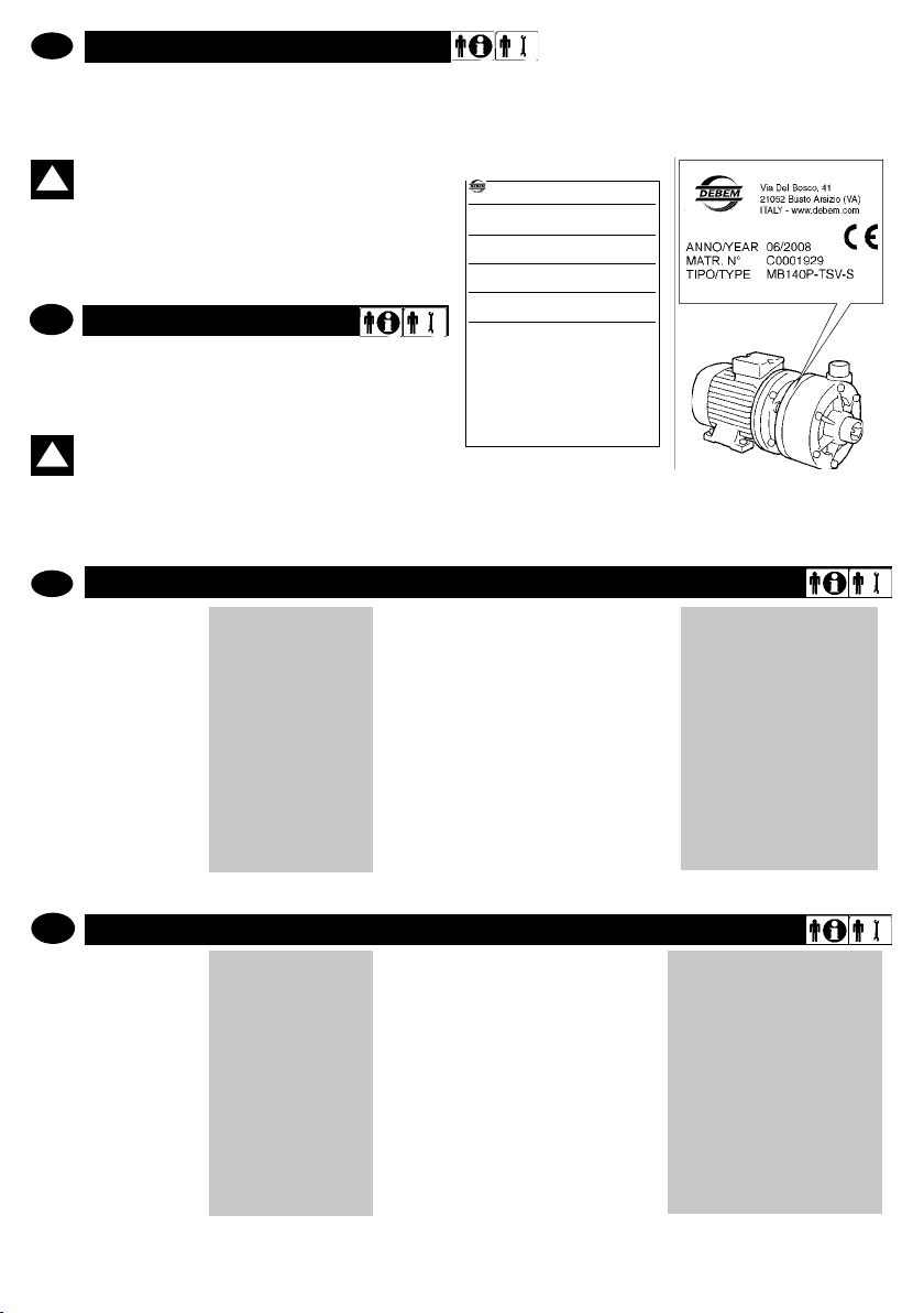
IDENTIFIKATION DER PUMPE
Jede Pumpe ist mit einem Typenschild ausgestattet, das die
Spezikationen und das Baumaterial angibt. Bei jeglicher
Kommunikation mit dem Hersteller, dem Händler oder den
autorisierten Kundenzentren sind diese Daten anzugeben.
ACHTUNG: es ist verboten, das Typenschild der
Pumpe und/oder die auf dem Typenschild angege-
!
benen Daten zu entfernen und/oder zu verändern.
Der Identikationscode *, der unter dem Punkt “TYP” des Typenschilds erscheint, speziziert die Zusammensetzung und
das Baumaterial der Pumpe, um die Eignung mit dem Produkt,
das gepumpt werden soll, zu bestimmen.
GB
PUMP IDENTIFICATION
Each pump is tted with an identication plate detailing its
specication and materials. This data must always be reported in
all communications to the manufacturer, dealer or service
centres.
WARNING: It is forbidden to remove and/or modify
!
the identication plate and/or the data therein.
The identication code * listed aside the TYPE heading, details
the pump composition and manufacturing materials in order
to determine its suitability and compatibility with the product
to be pumped.
IDENTIFIKATIONSCODE
D
MB 100
PUMPENMODELL
MB 080 = MB 80
MB 100 = MB 100
MB 110 = MB110
MB 120 = MB 120
MB 130 = MB 130
P-
MATERIAL DER PUMPE
P= polipropilene
EC = PVDF
TLV = DICHTLIPPE VITON
TLD = DICHTLIPPE EPDM
TSV = FALTENBALGDICHTUNG VITON
TSD = FALTENBALGDICHTUNG EPDM
TLV
ART DER DICHTUNG
N* = DREHSTROMMOTOR
A = MOTOR ATEX
M= EINPHASENMOTOR
MB 140 = MB 140
MB 150 = MB 150
MB 155 = MB 155
MB 160 = MB 160
MB 180 = MB 180
* Serienausstattung dreiphasiger Drehstrom-Asynchron-Motore (Eurospannung) (2 Pole) 50/60 Hz
GB
IDENTIFICATION CODE
MB 100
PUMP MODEL
MB 080 = MB 80
MB 100 = MB 100
MB 110 = MB 110
MB 120 = MB 120
MB 130 = MB 130
MB 140 = MB 140
MB 150 = MB.150
MB 155 = MB.155
MB 160 = MB.160
MB 180 = MB.180
* Standard motor is the three-phase induction type with European voltage (2-pole) 50Hz
debem.it
P-
PUMP MATERIAL
P= polypropylene
EC = PVDF
TLV = VITON LIP SEAL
TLD = EPDM LIP SEAL
TSV = VITON BELLOW SEAL
TSD = EPDM BELLOW SEAL
TLV
SEALING TYPE
N* = STANDARD MOTOR
A = ATEX MOTOR
M= SINGLE-PHASE MOTOR
6
N
MOTOR
N
MOTOR
Page 7

D
BESCHREIBUNG DER PUMPE
Die Horizontalkreiselpumpen aus Kunstharz MB wurden
für das Pumpen von Flüssigkeiten unter dem Anschlag mit
scheinbarer Viskosität von 1 bis 500 cps aus chemisch mit
den Bauteilen der Pumpe kompatiblen Materialien entworfen
und hergestellt. Der Betrieb der Pumpe ist bei Betriebstemperaturen der Flüssigkeit von +3°C bis zu maximal 65°C bei
Pumpen aus PP und 95°C bei Pumpen aus PVDF zulässig;
je nach Art der Materialzusammensetzung der Pumpe (siehe
TECHNISCHE CHARAKTERISTIKA S. 9) ist es notwendig,
auf der Anlage eine Schutzvorrichtung zu installieren, die den
Betrieb und/oder das Erreichen der Schwellentemperatur verhindert.
Die Kreiselpumpen MB sind für einen Betrieb bis zu einem
Maximum von 2900 Drehung/Minute vorgesehen, mit Motoren mit Direktantrieb mit hinterer Axialdehnung (für die Dilata-
GB
PUMP DESCRIPTION
Recommended use
MB horizontal, centrifugal pumps made from resin have been
designed and manufactured to pump below head liquids having an apparent viscosity between 1 and 500cps, and that
are chemically compatible with the components of the pump.
Fluid service temperatures must range from 3°C to a maximum
of 65°C for PP pumps and 95°C for PVDF pumps; according
to the type of material used to build the pump (pls refer to
TECHNICAL CHARACTERISTICS pg. 9).
MB centrifugal pumps are designed for a max working speed of
2900 revs/min, in direct drive with motors equipped with a rear
axial compensator (for dilation) having the following technicalmanufacturing characteristics:
D
Funktionsprinzip
Die Horizontalkreiselpumpen MB müssen unter entsprechenden Vorsichtsmaßnahmen unter dem Anschlag installiert werden, um die Bildung von Wirbeln und das folgende Ansaugen
von Luftblasen zu vermeiden. Sie darf ausschließlich bei GETAUCHTER PUMPE betrieben werden. Das Laufrad, das fest
mit der Pumpenwelle und der Direktkupplungsmotor verbunden ist, wird zu einer voreingestellten Geschwindigkeit (max.
2.900 Drehungen/Minute), betrieben; dadurch wird durch die
Zentrifugalkraft ein Ansaugen in der Hauptleitung und eine
Förderleistung in der Nebenleitung erzeugt.
ACHTUNG: jede Verwendung der Horizontalkrei-
!
selpumpe MB für anderweitige als die zuvor be-
tion) mit den folgenden technischen Konstruktionsmerkmalen:
DREIPHASIGER ASYNCHRONMOTOR 2 POLE
- Eurospannung;
- S1 –Status (Dauerbetrieb)
- Isolationsklasse F
- Schutzgrad IP 55
ACHTUNG: dort, wo der Variationsbereich der
Umgebungstemperatur und der Prozesstempera-
!
turen des Fluids in der Nähe der maximalen Werte
der Pumpe liegen (siehe TECHNISCHE CHARAKTERISTIKA S. 9), ist es je nach Baumaterial erforderlich, an der
Anlage eine Schutzvorrichtung zu installieren, die den
Betrieb und/oder das Erreichen des Schwellenwerts der
Temperatur verhindert.
THREE-PHASE/2 POLES ASYNCHRONOUS MOTOR
- Euro tension;
- S1 status (continuous service)
- Class F insulation;
- IP 55 protection rating.
WARNING: Whenever the variation range of envi-
!
ronmental temperature and of the uid process
temperature approaches the maximum pump temperatures according to the pump’s construction materials
(pls refer to TECHNICAL CHARACTERISTICS, pg 10), it is
necessary to safeguard the plant installing a protection
device stopping the pump and/or preventing it from reaching the threshold temperature.
schriebenen Nutzungen wird als unsachgemäße Verwendung betrachtet und ist daher vom Hersteller verboten.
Unsachgemäße Verwendung
Insbesondere IST die Verwendung der Pumpe MB für Folgendes VERBOTEN:
- das Pumpen von Benzin und/oder brennbaren Flüssigkeiten
- das Pumpen von üssigen Lebensmitteln;
- der Betrieb in einer anderen Drehrichtung als die festgelegte;
- der selbstansaugende Betrieb;
- der Betrieb mit Ansaugen im Beisein von Wirbeln, Turbulenzen oder Luftblasen;
der Vakuumbetrieb
- der Betrieb mit zu pumpenden, chemisch nicht mit den Baumaterialien kompatiblen Flüssigkeiten;
GB
Working principles
MB horizontal, centrifugal pumps must be installed below
head with appropriate procedures to avoid vortex formation
and consequent air bubble suction. The pump must work
ONLY when FLOODED.
The impeller - integrally joined to the shaft and to the direct
drive mounted motor- must be set in rotation at a preset speed
(max 2.900 revs/min); its centrifugal effect activates suction in
the main duct and delivery in the secondary duct
WARNING: use of MB horizontal, centrifugal
!
pumps or anything other than that previously described is to be considered improper use and is
forbidden by Debem.
Improper use
It is SPECIFICALLY forbidden to use MB pumps:
- for pumping petrol and/or ammable liquids;
- for pumping food liquids;
- with an opposite rotation to the one specied;
- in self-priming working conditions;
- for suction in the presence of vortexes, turbulence or air bubbles;
- for vacuum service;
- with liquids that are chemically incompatible with the manufacturing materials;
7
debem.it
Page 8
ATTENZIONE: qualsiasi altro
impiego della pompa centrifu-
ga orizzontale MB differente da
quanto precedentemente precisato
è considerato improprio e quindi
vietato dalla ditta Debem.
Usi impropri
In particolare È VIETATO l’uso della
pompa MB per:
- il pompaggio di benzina e/o liquidi
infiammabili;
- il pompaggio di liquidi alimentari;
- l’impiego con senso di rotazione
contrario a quello stabilito;
- l’impiego autoadescante;
- l’impiego con l’aspirazione in presen-
za di vortici, turbolenze o bolle d’aria;
- l’impiego a vuoto;
- l’impiego con liquidi da pompare incom-
patibili chimicamente con i materiali di
costruzione;
- l’impiego con prodotti in sospensione di
peso specifico superiore a quello del
liquido (esempio acqua con sabbia);
- con temperature e caratteristiche del
prodotto in disaccordo con le caratteri-
stiche della pompa;
- l’impiego con acque particolarmente
dure e/o molto cariche di prodotti da
riporto.
!
WARNING: use of MB
horizontal, centrifugal pumps or
anything other than that previously
described is to be considered
improper use and is forbidden by
Debem.
Improper use
It is SPECIFICALLY forbidden to use
MB pumps:
- for pumping petrol and/or flammable
liquids;
- for pumping food liquids;
- with an opposite rotation to the one
specified;
- in self-priming working conditions;
ATTENZIONE: qualsiasi altro
impiego della pompa centrifu-
ga orizzontale MB differente da
quanto precedentemente precisato
è considerato improprio e quindi
vietato dalla ditta Debem.
Usi impropri
In particolare È VIETATO l’uso della
pompa MB per:
- il pompaggio di benzina e/o liquidi
infiammabili;
- il pompaggio di liquidi alimentari;
- l’impiego con senso di rotazione
contrario a quello stabilito;
- l’impiego autoadescante;
- l’impiego con l’aspirazione in presen-
za di vortici, turbolenze o bolle d’aria;
- l’impiego a vuoto;
- l’impiego con liquidi da pompare incom-
patibili chimicamente con i materiali di
costruzione;
- l’impiego con prodotti in sospensione di
peso specifico superiore a quello del
liquido (esempio acqua con sabbia);
- con temperature e caratteristiche del
prodotto in disaccordo con le caratteri-
stiche della pompa;
- l’impiego con acque particolarmente
dure e/o molto cariche di prodotti da
riporto.
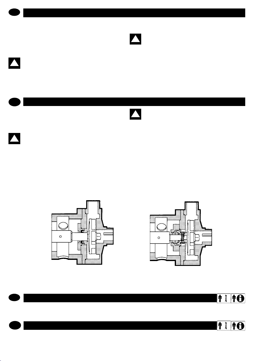
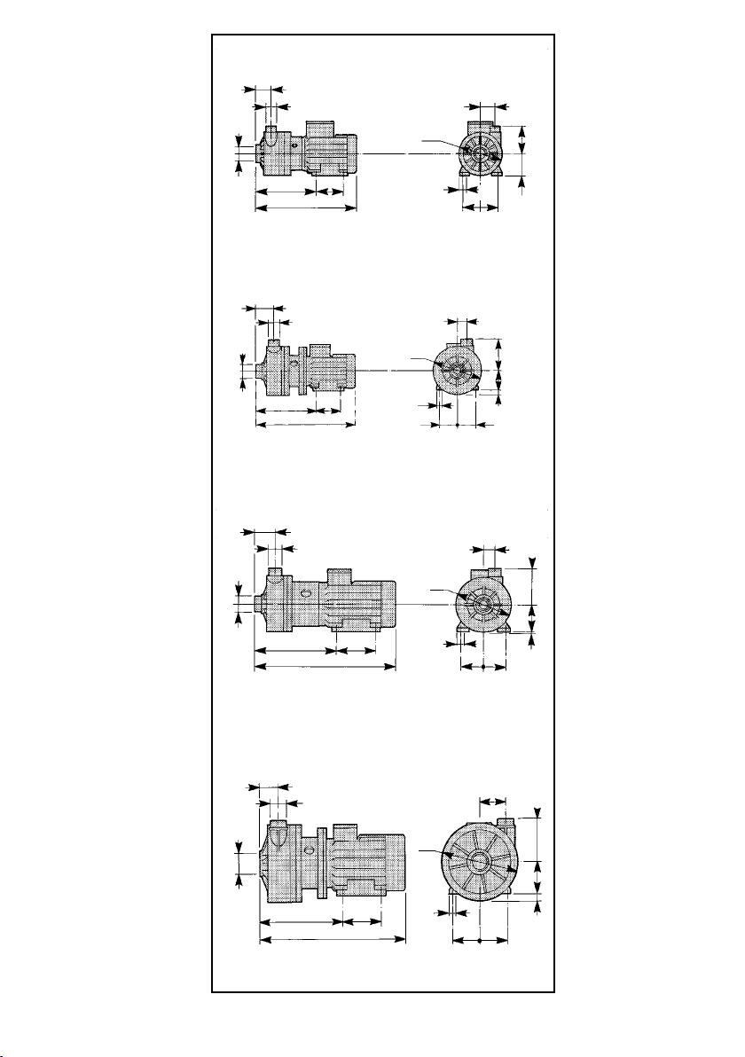
fig. 1
MB-TL
!
!
D
- der Betrieb mit Produkten in Suspension, deren spezi-
sches Gewicht über dem der Flüssigkeit (z.B. Wasser mit
Sand) liegt;
- mit Luftdrücken und Produkteigenschaften, die in Widerspruch zu den technischen Daten stehen;
- der Betrieb mit besonders hartem Wasser und Wasser mit
vielen Ablagerungen.
ACHTUNG: aufgrund der unendlichen Vielfalt von
!
Produkten und chemischen Zusammensetzungen
wird der Benutzer gehalten, über beste Kenntnisse der Reaktionen und Kompatibilität mit den Baumaterialien der Pumpe zu verfügen. Daher müssen vor der Anwendung fachmännisch alle notwendigen Inspektionen
und Tests ausgeführt werden, um die geringsten Risiken
GB
- with products in suspension that have a higher specic
weight than the liquid (e.g. water and sand);
- with product temperatures and characteristics of the pump;
- with water that is particularly hard and/ or full of deposits.
WARNING: due to the wide variety of products
!
and chemical compositions, the operator is con-
sidered to be the best evaluator of reactions and
compatibility with the pump’s construction materials.
Therefore, before use, carry out all necessary checks and
tests to avoid any possible hazardous situation, that cannot be predicted or for which the manufacturer cannot be
held liable.
MB-TL
fig. 1
TECHNISCHE CHARAKTERISTIKA
D
Die Daten bezüglich der Leistungen beziehen sich auf die Standardausführung. Die Werte des “NENNDURCHFLUSSES“ und der “FÖRDERHÖHE MAX” beziehen sich auf das Pumpen von Wasser bei 18°C mit freiem Einlass und Auslass.
TECHNICAL SPECIFICATIONS
GB
The data related to performance refer to standard procedures. The NOMINAL ow and the MAX head values refer to pumping
of water at 18°C with free-ow suction and delivery.
debem.it
zu vermeiden, die der Hersteller nicht voraussehen und
für die er nicht verantwortlich gemacht werden kann.
ACHTUNG: jede Verwendung der Pumpe entge-
!
gen den im Bedienungshandbuch und in der War-
tungsanleitung angegebenen Anweisungen führt
zum Erlöschen der Sicherheitsanforderungen.
Es wurden die Risiken in Zusammenhanf mit der Verwendung der Pumpe untern den spezischen im Bedienungshandbuch und Wartungsanleitung beschriebenen
Bedingungen analysiert: die Analyse der Risiken in Zusammenhang mit der Wechselwirkung mit anderen Komponenten des Systems ist dem Installateur zugewiesen.
WARNING: use of the pump that does not com-
!
ply with the instructions indicated in the use and
maintenance manual will cancel compliance to the
requirements for safety.
The risks associated with the use of the pump under the
exact conditions set forth in the use and maintenance
manual have been analysed, whilst the analysis of the
risks associated with the interface with other system
components must be carried out by the installer.
MB-TS
fig. 2
8
Page 9
MB 80
MB 80
MB 100
F
M
MB 100
I
N
A
B
P
L
MB 110
F
M
A
P
L
F
M
A
P
MB 110
MB 120
MB 120
MB 130
MB 130
B
MB 140
MB 140
B
L
O
N
O
N
O
H
E
C
I
H
E
D
C
I
H
E
D
C
MB 150
MB 150
F
M
A
P
MB 155
MB 155
MB 160
MB 160
MB 180
N
B
L
O
9
I
H
E
D
C
debem.it
Page 10

D
PUMPE MOTOR
abmessungen (mm)
Tech.
Art ANSAU.ØAABLASS
Daten
MB
TL
80
TS
MB
TL
100
TS
MB
TL
110
TS
MB
TL
120
TS
MB
TL
130
TS
MB
TL
140
TS
MB
TL
150
TS
MB
TL
155
TS
MB
TL
160
TS
MB
TL
180
TS
Die angegebenen Werte sind Richtwerte und nicht bindend f = Innengewinde m = Außengewinde
ØM
1” 1/2 f 1” m 325 1 71 47 89 48 112 90 140 Ø8 0,37 0,5 B3-B14 71K2
1” 1/2 f 1” m 325 1 71 47 89 48 112 90 140 Ø8 0,55 0,75 B3-B14 71G2
2” m 1” 1/2 m 406 20 80 75 130 40 140 100 203 Ø10 1,1 1,5 B3-B5 80B2
2” m 1” 1/2 m 456 10 90 75 130 40 140 100 203 Ø10 1,5 2 B3-B5 90S2
2” m 1” 1/2 m 468 10 90 75 130 40 140 125 203 Ø10 2,2 3 B3-B5 90L2
2” m 1” 1/2 m 505 2 100 75 130 40 160 140 203 Ø12 3 4 B3-B14 100L2
2” 1/2 f 2” m 529 12 112 67,5 153 97 190 140 274 Ø12 4 5,5 B3-B5 112M2
2” 1/2 f 2” m 620 18 132 67,5 153 97 216 140 274 Ø12 5,5 7,5 B3-B5 132S2
2” 1/2 f 2” m 628 18 132 67,5 153 97 216 140 274 Ø12 7,5 10 B3-B5 132S2
2” 1/2 f 2” m 695 18 132 68 158 96 216 178 300 Ø12 11 15 B3-B5 132S2
L D E F H I C B N
O
P KW HP
Ø
Debem kontaktierenask to Debem
MOTORFORM
MOTORGEHÄUSE
GB
PUMP MOTOR
dimension (mm)
Tech.
Type SUCT.ØADELIV.
Data
MB
TL
80
TS
MB
TL
100
TS
MB
TL
110
TS
MB
TL
120
TS
MB
TL
130
TS
MB
TL
140
TS
MB
TL
150
TS
MB
TL
155
TS
MB
TL
160
TS
MB
TL
180
TS
ØM
1” 1/2 f 1” m 325 1 71 47 89 48 112 90 140 Ø8 0,37 0,5 B3-B14 71K2
1” 1/2 f 1” m 325 1 71 47 89 48 112 90 140 Ø8 0,55 0,75 B3-B14 71G2
2” m 1” 1/2 m 406 20 80 75 130 40 140 100 203 Ø10 1,1 1,5 B3-B5 80B2
2” m 1” 1/2 m 456 10 90 75 130 40 140 100 203 Ø10 1,5 2 B3-B5 90S2
2” m 1” 1/2 m 468 10 90 75 130 40 140 125 203 Ø10 2,2 3 B3-B5 90L2
2” m 1” 1/2 m 505 2 100 75 130 40 160 140 203 Ø12 3 4 B3-B14 100L2
2” 1/2 f 2” m 529 12 112 67,5 153 97 190 140 274 Ø12 4 5,5 B3-B5 112M2
2” 1/2 f 2” m 620 18 132 67,5 153 97 216 140 274 Ø12 5,5 7,5 B3-B5 132S2
2” 1/2 f 2” m 628 18 132 67,5 153 97 216 140 274 Ø12 7,5 10 B3-B5 132S2
2” 1/2 f 2” m 695 18 132 68 158 96 216 178 300 Ø12 11 15 B3-B5 132S2
L D E F H I C B N
The above data is purely indicative and not binding f = female thread m = male thread
debem.it
10
O
P KW HP
Ø
MOTOR
SHAPE
MOTOR
CASING
Page 11

I
GB
ATTENZIONE:
il personale addetto all’installazione, all’ispezio-
ne e alla manutenzione della pompa deve avere
adeguata preparazione tecnica unita a cognizioni
idonee al campo di applicazione (compatibilità ade-
guate in materia e rischi connessi ad eventuali reazio-
ni chimiche del prodotto da pompare).
INSTALLATORE/MANUTENTORE ELETTRICO:
questa qualifica presuppone una piena conoscenza e
comprensione delle informazioni contenute nel manuale
d’uso del costruttore, competenza tecnica specifica per
effettuare gli interventi di natura elettrica di: allacciamento,
manutenzione ordinaria e/o riparazione.
INTERVENTI STRAORDINARI: identifica gli interventi
riservati a tecnici del servizio di assistenza eseguiti
solo presso le officine del Costruttore.
WARNING
personnel responsible for pump installation,
inspection and maintenance shall possess a suitable
technical background along with knowledge of the
field of application (compatibility of materials and risks
associated with possible chemical reactions of the
product being pumped).
ELECTRICAL/FITTER AND MAINTENANCE
ENGINEER
!
!
D
TECHNISCHE DATEN
Ansaugung
(f = Innengewinde / m = Außengewinde)
Anschluss Ablass
(m = Außengewinde)
Drehungen MAX Pumpe (nominal) Drehun-
Temperatur MAX Betrieb der
Pumpe
Förderhöhe MAX *
Durchuss MAX *
(bei 3000 Drehungen/Minute mit
Wasser bei 18°C)
Nettogewicht
Geräuschemission dB (A)
* Die Werte beziehen sich auf eine Pumpe mit freiem Einlass und Auslass mit Wasser bei 18°C.
GB
TECHNICAL DATA Unit MB80MB
Suction Connection
(f = female thread / m = male
thread)
Delivery connection
(m = male thread)
MAX pump rev. (nominal) giri/
MAX pumo temperature
MAX head * m 6 12 14 16 18 22 26 30 35 38
MAX ow rate*
(at 3000 rev/min with water at 18°C)
Net weight PP
Noise dB (A) 48 48 52 58 58 59 61 65
- PP
- PVDF
PP
PVDF
- PP C° 65 65 65 65 65 65 65 65 65 65
- PVDF C° 95 95 95 95 95 95 95 95 95 95
PVDF
Maßeinheit
gen/Min.
mc/h
inches 1” 1/2 f 1” 1/2 f 2” m 2” m 2” m 2” m 2” 1/2 f 2” 1/2 f 2” 1/2 f 2” 1/2 f
inches 1”m 1”m 1” 1/2 m 1” 1/2 m 1” 1/2 m 1” 1/2 m 1” 1/2 m 2” m 2” m 2” m
mc/h 3 6 20 25 30 40 45 50 55 75
MB80MB
Zoll
1” 1/2 f 1” 1/2 f 2” m 2” m 2” m 2” m 2” 1/2 f 2” 1/2 f 2” 1/2 f 2” 1/2 f
Zoll
C°
C°
m
Kg
Kg
2900 2900 2900 2900 2900 2900 2900 2900 2900 2900
min.
Kg
Kg
100MB110MB120MB130MB140MB150MB155MB160MB180
1”m 1”m 1” 1/2 m 1” 1/2 m 1” 1/2 m 1” 1/2 m 1” 1/2 m 2” m 2” m 2” m
2900 2900 2900 2900 2900 2900 2900 2900 2900 2900
65 65 65 65 65 65 65 65 65 65
95 95 95 95 95 95 95 95 95 95
6 12 14 16 18 22 26 30 35 38
3 6 20 25 30 40 45 50 55 75
8,5
8,5
9,5
48 48 52 58 58 59 61 65
8,5
9,5
15,5
9,5
16,52020,5
100MB110MB120MB130MB140MB150MB155MB160MB180
8,5
15,5
9,5
16,52020,5
22,5
23,52930
22,5
23,52930
404359,5
62,56770
404359,5
62,56770
65 65
65 65
96
99
96
99
* The values refer to a pump with open suction and delivery with water at 18°C
11
debem.it
Page 12

GARANTIE
D
PRESCRIZIONI DI SICUREZZA
Die Horizontalkreiselpumpe MB ist ein hochwertiges Produkte,
das bei den Endbenutzern vollsten Anklang ndet.
Sollte ein Fehler auftreten, ist der KUNDENSERVICE des HER
STELLERS, der Händler oder das Service-Center in Ihrer Nähe zu
kontaktieren. So schnell wie möglich erhalten Sie Unterstützung.
Geben Sie jedem Fall bitte folgende Informationen an:
A- die vollständige Adresse
B- die Kennzeichnung der Pumpe
C- die Beschreibung der Fehlstörung
Alle Pumpen MB werden durch folgende Formel abgedeckt:
1- Die Pumpe ist für 12 Monate auf alle mechanischen Teile, die
für fehlerhaft befunden werden, garantiert. Die Garantiezeit be
ginnt mit dem Lieferdatum.
2- Jeder Fehler muss innerhalb von 8 Tagen schriftlich dem Her
steller mitgeteilt werden.
3- Die Reparatur während der Garantiezeit erfolgt ausschließlich
in einer unserer Werkstätten nach Versand oder Zustellung der
defekten Pumpe.
4- Im Falle einer Reparatur oder bei Ersatz von Teilen der Pumpe
wird die Garantie nicht verlängert.
5- Die fehlerhaften Teile müssen dem Hersteller zurückgegeben
werden, der sich das Recht vorbehält, eine Überprüfung der Teile
in seiner eigenen Werkstatt durchzuführen, um den Fehler oder
externe Gründe, die den Schaden verursacht haben könnten, zu
ermitteln. Sollten die Teile nicht als fehlerhaft eingestuft werden,
behält sich der Hersteller das Recht vor, die gesamten Kosten der
zuvor unter Garantie ersetzten Teile in Rechnung zu stellen.
Der Hersteller übernimmt keine Kosten und Risiken für den Trans
port der defekten Teile oder der reparierten Teile oder der Ersatzteile, einschließlich etwaiger Zollgebühren. Die Reparatur oder der
Ersatz der defekten Teile deckt alle Garantieverpichtungen ab.
WARRANTY
GB
The high quality of MB horizontal, centrifugal pumps has been
conrmed to us on many occasions by the end users.
However, should any defect appear, please contact the
Manufacturer’s After-Sales Service, your dealer or the nearest
Customer Service Department who will help you as quickly
as possible.
In any case, please provide:
A – Your complete address
B – Pump identication
C – Description of the anomaly.
All the MB pumps are covered by the following warranty:
1. Guarantee on mechanical parts of all MB pumps is for 12
months. The warranty period is calculated from the date of
delivery.
2. Every fault must be notied to the Manufacturer within 8 days.
3. Repairs under warranty will only be carried out in our workshop after receiving the pump.
4. The replacement or repair of parts does not extend the
warranty.
5. Faulty parts must be forwarded to the Manufacturer who
reserves the right to test them in this own workshop in order to
identify the fault or any external reason that may have caused
it. Should the parts be found not faulty, the Manufacturer reserves the right to invoice the total cost of the parts that had
been replaced under this warranty.
The Manufacturer is not liable for costs and risks connected
to transportation of faulty and repaired parts and neither for
those supplied as spare parts, including possible custom duties.
debem.it
Die Garantie umfasst KEINE indirekten Schäden und Fabrikati
onsfehler. Zudem sind normale Verbrauchs- und Verschleißma-
-
terialien (Gleitringdichtungen, Dichtungen, usw.) von der Garantie
ausgeschlossen. Teile, die aufgrund von Nachlässigkeit oder einer
Fahrlässigkeit bei der Anwendung, falscher Installation, fehlender
oder unsachgemäßer Wartung, Transportschäden oder jeglichen
Umstand, der nicht auf Funktionsstörungen oder Verarbeitungs
fehler zurückzuführen ist, nicht in der Garantie abgedeckt.
Insbesondere sind von der Garantie ausgeschlossen:
- Schäden, die durch unsachgemäßen Gebrauch oder falsche In
stallation auf der Anlage verursacht wurden;
- anderweitige Verwendung der Pumpe als die vom Käufer beim
Moment der Bestellung angegebene;
- Schäden aufgrund der Verwendung unter trockenen Bedingun
gen und/oder bei Vorhandensein von Luftblasen;
- Schäden durch Abrieb;
- Schäden aufgrund von Fremdkörpern in der Pumpe;
- Schäden aufgrund umgekehrter Drehung des Motors und der
Pumpe;
- Verwendung der Pumpe bei höheren Temperaturen als zulässig;
- Schäden an den Gleitringdichtungen, (besonders anfällig für
Verschleiß), es sei denn, es bestehen offensichtliche Konstrukti
onsmängel;
- Schäden durch sehr hartes Wasser oder Wasser mit vielen Ab
lagerungen;
Die Garantie ist in allen Fällen der unsachgemäßen oder miss
bräuchlichen Anwendung und der Nichtbeachtung der in diesem
Handbuch enthaltenen Informationen ausgeschlossen.
-
Für alle Streitigkeiten ist das Gericht von Busto Arsizio zu
ständig.
Repair and replacement of faulty parts entirely fulls the warranty.
This warranty DOES NOT cover any indirect damages, in
particular lost production. Moreover, the warranty does not
cover any consumable materials (mechanical seals, gaskets).
The warranty does not include parts damaged as a consequence of carelessness, neglect, incorrect installation, lack of
and/or incorrect maintenance, or damages due to transportation or to any other reason or event that is not directly linked to
functioning or manufacturing defects.
The following are specically excluded from the warranty:
- any damage caused by incorrect use or installation of the plant;
- use of the pump other than that declared by the purchaser
at the time of order;
- any damage cause by working in dry conditions and/or presence of air bubbles;
- any damage caused by abrasion;
- any damage caused by foreign matters in the pump;
- any damage caused by reverse rotation of the pump or motor;
- any damage caused by using the pump above the maximum
allowed temperature;
- any damage to mechanical sealing (being subject to wear),
except when a manufacturing defect is obvious;
- any damage caused by water with a high content of deposits.
The warranty is void in all cases of improper or incorrect use
and in case of negligence in following the information herein
contained.
For any controversy, the place of jurisdiction is Busto
Arsizio.
12
-
-
-
-
-
-
-
-
Page 13
SICHERHEITSANFORDERUNGEN
D
PRESCRIZIONI DI SICUREZZA
Gefährliche oder riskante Praktiken oder Praktiken, die nicht mit den
Sicherheitsanforderungen und dem in diesem Handbuch Beschrie
benen übereinstimmen, können zu schweren Verletzungen, Materialschäden und sogar zum Tod, für die nicht der Hersteller verantwortlich gemacht werden kann, führen.
ACHTUNG: diese Anweisungen sind für die Einhaltung
der Pumpe gemäß der Sicherheitsanforderungen un
!
verzichtbar und müssen daher: verfügbar, bekannt und
verstanden worden sein und genutzt werden.
ACHTUNG: das für die Installation, die Inspektion und
die Wartung der Pumpe verantwortliche Personal muss
!
über eine angemessene technische Ausbildung sowie
ausreichende Kenntnisse über den Anwendungsbereich verfü
gen (Kompatibilität und Risiken in Verbindung mit möglichen
chemischen Reaktionen des zu pumpenden Produkts).
ACHTUNG: jede Verwendung der Pumpe entgegen den
im Bedienungshandbuch und in der Wartungsanlei
!
tung beschriebenen Anweisungen führt zum Erlöschen
der Garantie- und Sicherheitsanforderungen.
ACHTUNG: vor dem Eingriff an der Pumpe und/oder
vor der Ausführung von Wartungsarbeiten oder Repa
!
raturen muss:
A- das Produkt, das gepumpt wird, aus dem Kreislauf abgelassen
werden;
B- für die interne Reinigung mit einem geeigneten (nichtbrennbaren
Fluid) gesorgt werden;
C- der Motor der Pumpe gestoppt werden;
D- die Absperrventile zum Produkt (Auslass und Einlass) manuell
geschlossen werden;
E- die Versorgungsspannung des Motors der Pumpe abgetrennt
werden;
F- jedem Eingriff die geeignete persönliche Schutzausrüstung ange
SAFETY INSTRUCTIONS
GB
Dangerous or hazardous practices or practices not
complying with the safety rules and with that recommended
herein may cause injuries, material damage and even death
for which the manufacturer cannot be held responsible.
WARNING: these instructions are indispensable
for the pump to comply with safety requirements,
!
therefore they must be made known, available and
abided to.
WARNING: the personnel in charge of installing,
!
inspecting and servicing the pumps must have ad
equate technical knowledge and training in the eld
of application (compatibility and hazards related to possible
chemical reaction of the product/s to pump).
WARNING: use of the pump that does not comply
to the instructions indicated in the use and mainte
!
nance manual will invalidate all warranty and safety
requirements.
WARNING: before any operation on the pump and/
or before any maintenance or repair, proceed as
!
follows:
A – discharge the product being pumped;
B – proceed with washing the inside with appropriate liquid
(non-ammable);
C – stop the pump motor;
D – close the manual, shut-off valves (suction and delivery of
product);
E - section power to the pump motor;
F – Wear suitable individual protection before any intervention
legt werden (Gesichtsschutz, Handschuhe, geschlossene Schuhe,
Schürzen, usw.).
-
ACHTUNG: versichern Sie sich vor Verwendung der
!
Pumpe, dass das zu pumpende Fluid mit den Bauma
terialien kompatibel ist: KORROSIONSGEFAHR, AUS-
STRÖMEN DES PRODUKTS UND/ODER EXPLOSIONEN AUF-
-
GRUND CHEMISCHER REAKTIONEN.
Für die Installation und den Einsatz müssen Sie die folgenden
Vorsichtsmaßnahmen einhalten:
- überprüfen Sie, dass die Pumpe getaucht ist und der Pegel über
dem Mindeststand steht (wenigstens 0,5m);
- überprüfen Sie, dass im behandelten Fluid keine Feststoffe vorhan
-
den sind oder sein können;
- überprüfen Sie, dass keine Einschränkungen an der Ansaugung
der Pumpe vorhanden sind, um Kavitationserscheinungen oder
Kraftanstrengung des elektrischen Motors zu vermeiden;
- überprüfen Sie, dass die Verbindungsleitungen geeignet und wider
-
standfähig sind und dass die Pumpe nicht unter dem Gewicht leidet;
- wenn die Pumpe über einen langen Zeitraum unbenutzt bleibt,
reinigen Sie sie sorgfältig, indem Sie eine Reinigungsüssigkeit
(nichtbrennbar), die mit den Materialien der Pumpe kompatibel ist,
-
zirkulieren lassen;
- wenn die Pumpe über einen langen Zeitraum ausgeschaltet bleibt,
ist es ratsam, für einige Minuten sauberes Wasser zirkulieren zu las
sen, um das Risiko von Verkrustungen zu vermeiden;
- schützen Sie die Pumpe immer vor möglichen Stößen, die verse
hentlich durch sich bewegende Teile entstehen können oder vor verschiedenen schlagenden Materialien, die sie beschädigen und/oder
bei Kontakt mit ihren Materialien reagieren können;
- schützen Sie die Umgebung vor Spritzern durch unbeabsichtigte
Ausfälle der Pumpe;
-
(masks, gloves, closed shoes, aprons, etc.).
WARNING: before using the pump, ensure that the
!
uid to pump is compatible with the manufacturing
materials: CORROSION, LEAKAGE AND/OR EZPLO
SION HAZARSDS DUE TO CHEMICAL REACTIONS.
For the installation and use, take the following precautions:
- check that the pump is ooded and the level is at least 0,5 m
higher;
-
- Check that no solid particles are or could oat in the uid;
- Check that there are no constraints to the pump suction, thus
avoiding cavitations and electrical motor strain;
- Check that the connecting pipes are suitable and resistant and
that the pump does not bear their weight;
- If the pump is to be inactive for long periods, clean it thoroughly
-
with a detergent uid (non-ammable) compatible with the pump’s
construction materials;
- if the pump must be turned off for a long period of time, be
fore doing so circulate clean water for some minutes to avoid
incrustations;
- always protect the pump against possible collisions caused by
moving means or by various blunt materials that may damage it
or react with its materials;
- protect the pump’s surrounding environment from splashes
caused by accidental pump failure;
- Supply an adequate guard to collect and direct the treated
product that could leak.
13
debem.it
-
-
-
-
-
-
-
Page 14

D
PRESCRIZIONI DI SICUREZZA
- sorgen Sie für einen angemessenen Schutz, der mögliche Leckagen des Produkts durch einen übermäßigen
Verschleiß und/oder Vernachlässigung der Wartung sammelt und auffängt;
ACHTUNG: der Trockenlauf der Pumpe MB ist
!
VERBOTEN. Der Trockenlauf verursacht neben
Schäden an der Keramikbuchse die Verschmelzung von Elementen in Gleitreibung und daraus folgend,
einen möglichen Brand.
ACHTUNG: die Verwendung der Pumpe für
selbstansaugende Installationen ist VERBOTEN;
!
die Saugleitung muss immer unter dem Anschlag
und entfernt von Wirbeln und Turbulenzen, die das Zurückhalten der Luft und Schäden an der Dichtung verursachen können, installiert sein.
ACHTUNG: beim Pumpen von aggressiven, gifti-
gen oder gesundheitsschädlichen Flüssigkeiten
!
muss ein angemessener Schutz für die Rückhaltung, für das Auffangen und für die Meldung des Produkt
im Fall von Produktleckagen installiert werden: GEFAHR
DER VERSCHMUTZUNG, KONTAMINATION, VERLETZUNG UND/ODER TOD.
ACHTUNG: es ist die Verwendung der Pumpe mit
nicht mit den Materialien der Komponenten kom-
!
patiblen Flüssigkeiten oder in Umgebungen, in
denen nicht kompatible Flüssigkeiten vorhanden sind,
verboten.
ACHTUNG: es ist die Installation der Pumpe ohne
!
Absperrventile des Produkts auf der Eintritts- und
Auslassseite, um im Falle von Leckagen das Abtrennen auszuführen, verboten: GEFAHR VON UNKONTROLLIERTEM ENTWEICHEN DES PRODUKTS.
ACHTUNG: wo der Benutzer das Risiko einer
!
Überschreitung der Temperaturgrenzen, die in
diesem Handbuch festgelegt sind, befürchtet, ist
es notwendig auf dem System eine Schutzvorrichtung zu
installieren, die den Betrieb und/oder das Erreichen der
Schwellentemperatur (Fluid und Umgebung) von 95°C für
Pumpen aus PVDF und 65°C für die Pumpen aus PP (Polypropylen) verhindert.
ACHTUNG: die Pumpe muss immer unabhängig
!
von anderen Organen mit denen Sie verbunden
ist, geerdet sein.
ACHTUNG: aggressive, giftige oder gefährliche
Flüssigkeiten können zu schweren Körperverlet-
!
zungen und/oder Gesundheitsschäden führen.
Daher ist es verboten, dem Hersteller oder einem Service-Center einen Pumpe, die solche Produkte enthält,
zurückzugeben: entleeren und reinigen Sie den internen
Produktkreislauf und führen Sie vor dem Versand eine
Reinigung und Behandlung durch.
ACHTUNG: die Pumpenmodelle, die Komponen-
!
ten oder Teile aus Aluminium, die in Kontakt mit
dem Produkt sind, enthalten, können nicht für
das Pumpen von III-Trichlorethan, Methylenchlorid oder
Lösungsmitteln auf Basis von halogenierten Kohlenwasserstoffen verwendet werden EXPLOSIONSGEFAHR
AUFGRUND CHEMISCHER REAKTIONEN.
ACHTUNG: überprüfen Sie, dass während des
!
Betriebs keine ungewöhnlichen Geräusche auf-
treten. In diesem Fall blockieren Sie unverzüglich
den Betrieb der Pumpe.
GB
WARNING: It is FORBIDDEN to expose an MB pump
!
to dry working conditions; this could damage the
sealing, cause the elements exposed to horizontal
friction to melt and possibly cause a re.
WARNING: it is FORBIDDEN to use the pump for
!
self priming installation; the suction conduits must
always be installed below head and away from
vortexes or turbulence that could cause air retention and
damage the sealing.
WARNING: when pumping aggressive, toxic or haz
!
ardous uids, the pump must be tted with a suitable
guard to contain collect and signal the product in
case of leakage: POLLUTION, CONTAMINATION, INJURY
AND/OR DEATH.
WARNING: It is forbidden to use the pump with uids
!
that are incompatible with the components materials
or in an environment with non-compatible uids.
WARNING: It is forbidden to install the pump without
tting the shut-off valves at the suction and delivery
!
of the product that enable the sectioning required
in case of leakage: HAZARD OF UNCONTROLLED
LEAKAGE OF THE PRODUCT.
WARNING: Should the user think that the tempera
!
ture limits set forth in this manual may be exceeded
debem.it
during service, a protection device must be installed on the
system to prevent global temperature (uid + ambient) from
reaching temperatures higher than 95°C for PVDF pimps and
65°C for PP (polypropylene) pumps.
WARNING: The pump must always be earthed, inde
pendently from any other equipment connected to it.
!
WARNING: aggressive, toxic or hazardous uids
can cause severe physical injuries and/or damages
!
to health, consequently it is forbidden to return a
pump containing such products to either the manufacturer
or to a service centre. Empty and wash the internal circuit
and treat the pump before delivering it.
WARNING: the models with aluminium parts or com
ponents in contact with the product cannot be used
!
for pumping III-trichloroethylene, chlorine methylene
or any halogenated, hydrocarbon-based solvent: EXPLO
SION HAZARD DUE TO CHEMICAL REACTION.
WARNING: Check that there is no abnormal noise
during functioning. In this case, stop the operation
!
of the pump immediately.
WARNING: check that the output uid does not carry
air or gas; in this case, stop the pump immediately
!
-
and resolve the problem before restarting it.
14
-
-
-
Page 15

D
PRESCRIZIONI DI SICUREZZA
ACHTUNG: überprüfen Sie, dass im Fluid im Auslass keine Luft oder Gas vorhanden ist. Ansonsten
!
stoppen Sie den Betrieb der Pumpe unverzüglich
und sorgen Sie vor dem Neustart für die Beseitigung der
Fehlstörung.
ACHTUNG: die Verwendung der Pumpen MB für
besonders hartes Wasser und/oder Wasser mit
!
vielen Ablagerungen, die anomale Verkrustungen
auf der mechanischen Dichtung verursachen, ist verboten.
ACHTUNG: die interne Keramikbuchse ist eine
Komponente, die einem starken Verschleiß unter
!
liegt. Ihre Haltbarkeit wird stark von den Anwen-
dungsbedingungen und den chemischen und physika-
-
GB
WARNING: it is prohibited to use MB Pumps with
!
water that is particularly hard and/or has a high
content of deposits as it may cause anomalous
incrustations on the mechanical seal.
WARNING: the inner sealing component is exceed-
!
ingly exposed to wear. Its life span is strongly
inuenced by the working conditions, chemical and
physical stress or lack of maintenance. Tests carried out on
thousand of pumps indicate that its standard life span is in
excess of 1,500 hours. For safety reasons, in environments
TRANSPORT UND POSITIONIERUNG
D
Die für die Montage/Demontage verantwortlichen Bediener müssen
über die Gefahren, auch wenn sie noch so gering sind, in Verbindung
mit der Verwendung von mechanischen Werkzeugen ausgebildet
werden.
Nach Erhalt überprüfen Sie, dass die Verpackung und die Pumpe in
takt sind und keine Schäden davongetragen haben. Ansonsten müssen Sie wie folgt vorgehen:
1 Je nach Größe und Gewicht der Lieferung wird sie in einer Karton
verpackung, auf Paletten oder in einer Kiste geliefert: öffnen Sie sie bei
Empfang und entfernen Sie die Verpackung.
2 Entnehmen Sie das Bedienungshandbuch und die Wartungsanleitung und gehen Sie wie beschrieben vor.
3 Heben Sie die Pumpe je nach dem auf der Kennzeichnung angegebenen Gewicht mit einer entsprechenden Ladevorrichtung.
4 Führen Sie eine Überprüfung der Befestigung aller Schrauben der
Pumpe aus.
TRANSPORTING AND POSITIONING
GB
The operators in charge of the assembly / disassembly must
be informed and trained on the dangers relating to the use of
mechanical tools, even small ones .
When receiving the goods, check that the pump packaging is undam
aged; afterwards proceed as follows:
1 According to the equipment size and weight the plant is either pack
aged with cardboard, boxes or on pallets. Open and discard the packaging;
2 Consult the Use and Maintenance Manual and comply with its
instructions;
3 Lift the pump with appropriate lifting means, suitable to the weight in
dicated on the Id plate.
4 Check the correct tightening of all screws.
NOTE: MB pumps are supplied complete with motor. In case of future
-
-
-
-
-
15
lischen Beanspruchungen oder der fehlenden Wartung
beeinusst. Aus Tests an Tausenden installierten Exemp
laren von Pumpen übersteigt die normale Haltbarkeit 1.500
Stunden. Aus Sicherheitsgründen müssen der Ausbau und
die Überprüfung der Dichtung alle 500 Stunden und ihr Er
satz alle 1.500 Stunden stattnden.
HINWEIS: Für den Ersatz der Verschleißteile verwen
den Sie nur Original-Ersatzteile.
Bei Nichtbeachtung der oben aufgeführten Vorschriften
können Gefahren für den Bediener, die Techniker, die ex
ponierten Personen, die Pumpe und/oder die Umwelt entstehen, für die der Hersteller nicht haftbar ist.
characterised by the presence of aggressive products, it
is recommended to disassemble and check the sealing
every 500 hours and to replace them every 1,500 hours.
WARNING: Only use original spare parts for replacements.
The manufacturer is not liable for hazards to the operator,
technicians, people exposed, the pump and/or the environment caused by non-compliance with the above.
ANMERKUNG: Die Pumpen MB werden vollständig mit Mo
tor geliefert. Für zukünftige Umsetzungen müssen Sie, falls
die Pumpe ohne Motor ist, bevor Sie mit der Positionierung
fortfahren, für seine Montage sorgen. Gehen Sie dazu wie im Kapitel
“MONTAGE DES ELEKTRISCHEN MOTORS” beschrieben vor.
ACHTUNG: die für die Pumpe MB vorgesehene Positi
onierung und die Befestigung erfolgt horizontal durch
!
Befestigung an der Decke oder auf dem Boden auf den
entsprechenden Füßen des Motors. Die Horizontalkreiselpumpen sind nicht selbstansaugend und müssen daher in der Nähe
der Entnahmestelle ohne Bildung von Siphonen auf der Ansaugung installiert werden.
6 Positionieren Sie die Pumpe ordnungsgemäß am Aufstellungsort
(so nah wie möglich am Entnahmepunkt) und sorgen Sie für die Be
festigung auf den Füßen des Motors mit den entsprechenden Mutterschrauben. Sorgen Sie für ausreichend Platz für eventuelle Wartungsarbeiten.
handling, if the pump is detached from the motor, before pro
ceeding with its positioning it must be assembled as described
in the Chapter: “ASSEMBLY OF ELECTRIC MOTOR SEAL
ING”.
WARNING: the pumps are designed to be positioned and xed
horizontally from the ceiling using hangers or on the
oor on the feet of the motor. The horizontal, centrifugal
!
pumps are not self priming, therefore they must always
be installed next to the suction point, and without forming siphons
in suction.
6. Correctly position the pump in the installation area (as close as pos
sible to the suction point) and proceed with bolting the motor feet appropriately. Ensure that adequate space is left for future maintenance
operations.
debem.it
-
-
-
-
-
-
-
-
-
-
Page 16

4 Effettuare una verifica del serraggio di
tutte le viti della pompa.
NOTA
Le pompe MB vengono fornite
complete di motore. Nel caso di future
movimentazioni, se la pompa è in
assenza del motore, prima di procedere
al posizionamento bisognerà provvedere
al suo montaggio operando come
descritto al Capitolo “MONTAGGIO
DELLA TENUTA DEL MOTORE ELET-
6 Posizionare correttamente la pompa sul
luogo di installazione (più vicina possi-
bile al punto di prelievo) e provvedere
allo staffaggio sui piedini del motore con
appositi bulloni. Prevedere uno spazio
sufficiente per le eventuali future manu-
tenzioni.
OK
6 Posizionare correttamente la pompa sul
luogo di installazione (più vicina possi-
bile al punto di prelievo) e provvedere
allo staffaggio sui piedini del motore con
appositi bulloni. Prevedere uno spazio
sufficiente per le eventuali future manu-
tenzioni.
6. Correctly position the pump in the
installation area (as close as
possible to the suction point) and
OK
OK
200 mm
livello min
min levele
6 Posizionare correttamente la pompa sul
luogo di installazione (più vicina possi-
bile al punto di prelievo) e provvedere
allo staffaggio sui piedini del motore con
appositi bulloni. Prevedere uno spazio
sufficiente per le eventuali future manu-
tenzioni.
6. Correctly position the pump in the
installation area (as close as
possible to the suction point) and
proceed with bolting the motor feet
appropriately. Ensure that adequate
space is left for future maintenance
operations.
1
2
3
ISTRUZIONI PER L’USO E LA
MANUTENZIONE
INSTRUCTIONS FOR USE AND
MAINTENANCE
MB
4 Effettuare una verifica del serraggio di
tutte le viti della pompa.
NOTA
Le pompe MB vengono fornite
complete di motore. Nel caso di future
movimentazioni, se la pompa è in
assenza del motore, prima di procedere
al posizionamento bisognerà provvedere
al suo montaggio operando come
descritto al Capitolo “MONTAGGIO
DELLA TENUTA DEL MOTORE ELET-
TRICO”.
4 Check the correct tightening of all
screws.
NOTE:
MB pumps are supplied complete
with motor. In case of future handling,
if the pump is detached from the motor,
before proceeding with its positioning it
must be assembled as described in
the Chapter: “ASSEMBLY OF
ELECTRIC MOTOR SEALING”.
POMPE CENTRIFUGHE ORIZZONTALI
HORIZONTAL CENTRIFUGAL PUMPS
1
4 Effettuare una verifica del serraggio di
tutte le viti della pompa.
NOTA
Le pompe MB vengono fornite
complete di motore. Nel caso di future
movimentazioni, se la pompa è in
assenza del motore, prima di procedere
al posizionamento bisognerà provvedere
al suo montaggio operando come
descritto al Capitolo “MONTAGGIO
DELLA TENUTA DEL MOTORE ELET-
TRICO”.
POMPE CENTRIFUGHE ORIZZONTALI
HORIZONTAL CENTRIFUGAL PUMPS
1
2
ISTRUZIONI PER L’USO E LA
MANUTENZIONE
INSTRUCTIONS FOR USE AND
MAINTENANCE
MB
4 Effettuare una verifica del serraggio di
tutte le viti della pompa.
NOTA
Le pompe MB vengono fornite
complete di motore. Nel caso di future
movimentazioni, se la pompa è in
assenza del motore, prima di procedere
al posizionamento bisognerà provvedere
al suo montaggio operando come
descritto al Capitolo “MONTAGGIO
DELLA TENUTA DEL MOTORE ELET-
TRICO”.
4 Check the correct tightening of all
screws.
NOTE:
MB pumps are supplied complete
with motor. In case of future handling,
if the pump is detached from the motor,
before proceeding with its positioning it
must be assembled as described in
the Chapter: “ASSEMBLY OF
ELECTRIC MOTOR SEALING”.
POMPE CENTRIFUGHE ORIZZONTALI
HORIZONTAL CENTRIFUGAL PUMPS
allgemeine
Warnung
General
Danger Sign
Rauchverbot
ISTRUZIONI PER L’USO E LA
MANUTENZIONE
INSTRUCTIONS FOR USE AND
MAINTENANCE
1
MB
OK
Positionieren Sie die folgenden Verbots- und Warnschilder in der Nähe des Aufstellungsortes der Pumpe
Gefahr von
korrosivem
Material
Danger
Corrosive
Material
es muss ein
Schutzanzug
getragen
werden
Gefahr von
brennbarem
Material
Danger
Flammable
Material
es muss eine
Schutzbrille
getragen
werden
die Atemwege
es müssen
geschützt
werden
livello min
min levele
OK
Gefahr von
explosivem
Material
Danger
Explosive
Material
2
200 mm
es müssen
Handschuhe
getragen
werden
Gefahr von
giftigem
Material
Danger Toxic
Material
es müssen
geschlossene
Schuhe
getragen
werden
3
Gefahr von
Spritzern von üs
sigem glühendem
Material
Danger
Incandescent
Liquid Sprinkles
es muss eine
Schutzmaske
getragen werden
Gefahr von
Elektrizität
danger high
voltage
6
Verbot von
offenen
Flammen
Prohibition
on Open
Flames’ Use
es ist
verboten,
Brände mit
Wasser zu
löschen
4
No smoking
debem.it
Safety overalls
must be worn
Put the following prohibition and danger signs near the place where the pump is installed
Eye
protection
must be worn
Respiratory
equipment
must be worn
Safety gloves
must be worn
16
Safety boots
must be worn
Face
protection
must be worn
prohibition of
putting out res
with water
Page 17

D- eventuali filtri di aspirazione
devono essere a cestello oppor-
tunamente sovradimensionati
(circa 3 volte la sezione di
aspirazione della pompa, per
evitare perdite di carico);
E- il pescante del tubo di aspira-
zione deve essere alloggiato
al’interno di idoneo stramazzo e
lontano da vortici, turbolenze e
scarichi liberi;
F- prevedere un dispositivo di
livello che determini l’arresto
del motore della pompa al di
sotto del livello minimo.
Il trasporto e posizionamento sono
così terminati.
A
D – any suction filters must be of
the basket-type and
D- eventuali filtri di aspirazione
devono essere a cestello oppor-
tunamente sovradimensionati
(circa 3 volte la sezione di
aspirazione della pompa, per
evitare perdite di carico);
E- il pescante del tubo di aspira-
zione deve essere alloggiato
al’interno di idoneo stramazzo e
lontano da vortici, turbolenze e
scarichi liberi;
F- prevedere un dispositivo di
livello che determini l’arresto
del motore della pompa al di
sotto del livello minimo.
Il trasporto e posizionamento sono
così terminati.
A
B
D – any suction filters must be of
the basket-type and
appropriately over-
dimensioned (approx 3 times
the pump suction diameter, to
avoid loss of pressure);
E – the dip tube of the suction pipe
must be housed inside the weir
and away from vortexes,
turbulence and open drains;
F – fit a level regulator device that
can halt the motor when the
pump is under the minimum
level.
Transportation and positioning are
now completed.
D
PRESCRIZIONI DI SICUREZZA
ACHTUNG: der Betrieb der Pumpen MB mit
!
schweren Elementen in Suspension oder der Tro-
ckenbetrieb kann neben Schäden an der Dichtung
auch einen Verschmelzung der Elemente in Gleitreibung
und ein daraus folgendes mögliches Feuer verursachen.
Daher sind folgende Regeln zu beachten:
A- die Pumpe ist nicht selbstansaugend und muss immer
unterhalb des Anschlags installiert sein;
B- Das Tauchrohr der Saugleitung der Pumpe muss so
geformt sein, um Verstopfungen durch das Ansaugen
von Schlamm und schweren Stoffen zu verhindern und
fern von Wirbeln oder Füllrohren der Wanne installiert
GB
WARNING: MB pumps working with heavy elements
!
in suspension or in dry conditions can damage the
sealing as well as causing the fusion of sliding fric-
tion parts that may give rise to re, therefore the following
rules must be complied with:
A – the pump is not self priming and must be positioned
below head:
B – the dip tube of the suction pipe must be bent to avoid
clogging due to reux, grit and heavy matter, and it must
be kept away from vortexes or the tank lling pipes;
A
sein;
C- die Ansaugleitung darf keine Siphone bilden;
D- etwaige Sauglter müssen vom Korbtyp und entsprechend überdimensioniert (etwa 3 Mal der Ansaugdurchmesser der Pumpe, um Druckverluste zu vermeiden) sein;
E- das Tauchrohr der Saugleitung muss in einem geeigneten Überlauf und entfernt von Wirbeln, Turbulenzen
und freien Ableitungen in der Wanne untergebracht sein;
F- sorgen Sie für einen Füllbegrenzer, der den Stopp des
Pumpenmotors bei Stand unter dem Mindestwert bestimmt.
Der Transport und die Positionierung sind somit beendet.
C – the suction pipe must not create siphons;
D – any suction lters must be of the basket-type and
appropriately overdimensioned (approx 3 times
the pump suction diameter, to avoid loss of pressure);
E – the dip tube of the suction pipe must be housed
inside the weir and away from vortexes, turbulence and
open drains;
F – t a level regulator device that can halt the motor when
the pump is under the minimum level.
Transportation and positioning are now completed.
D E F
OK
livello minimo
min. level
B
C
17
debem.it
Page 18

D
ANSCHLUSS DES PRODUKTKREISLAUFS
PRESCRIZIONI DI SICUREZZA
Nachdem Sie die Positionierung durchgeführt haben, ist es
möglich, den Anschluss der Pumpe an den Produktkreislauf
anzuschließen. Der Vorgang wird im Folgenden beschrieben:
ACHTUNG: für die Verbindungen des Produktkreis
laufs an die Pumpe dürfen nur Anschlüsse mit zy-
!
lindrischem Rohrgewinde aus mit dem zu pumpenden Fluid und dem Baumaterial des Dämpfers kompatiblen
Material verwendet werden.
BSP: Pumpe aus PP = Anschluss PP
1. Installieren Sie auf dem Anschluss des Ablass- und Einlass
kollektors ein manuelles Kugelventil (mit vollem Durchgang) mit
dem gleichen Durchmesser des Anschlusses der Pumpe (nie
kleiner), um so das Auffangen des Fluids bei Leckagen und/
oder zukünftigen Wartungsarbeiten zu gewährleisten.
2. Sorgen Sie für die Installation der Muffen für die Befestigung
der Schläuche auf beiden manuellen Ventilen.
ACHTUNG: die Verbindungsleitungen an die Kol
lektoren der Pumpe müssen FLEXIBEL UND MIT
!
EINER STEIFEN SPIRALE VERSTÄRKT SEIN und
mit einem Durchmesser, der niemals kleiner als die Verbin
dungsstelle ist. Verwenden Sie für viskose Flüssigkeiten
Leitungen mit einem vergrößerten Durchmesser, beson
ders auf der Absaugung.
Der DIREKTE Anschluss an die Pumpe mit starren Me
tallrohren (an Pumpen aus Kunststoff und/oder mit konischem Gewinde) ist verboten, da dadurch starke Belastungen und/oder Vibrationen und ein Bruch der Kollektoren
und anderer Teile der Pumpe verursacht werden können.
Benutzen Sie immer exible Schläuche mit Anschlussstü
cken aus dem gleichen Material wie das der Pumpe (PP mit
PP, PVDF mit PVDF).
Ebenso ist die Verwendung von Gewindesicherungsstof
fen und/oder Teonpaste verboten. Der Installateur muss
bei der Montage auf die Zentrierung der Anschlüsse ach
ten, um Risse bzw. ein Nachgeben der Gewinde zu vermeiden.
Außerdem ist zu kontrollieren, ob nicht eventuell über
schüssiges PTFE-Band und ein übermäßiger Anzugsdruck
den Kollektor oder andere Teile der Pumpen zu stark be
lastet.
Besondere Beachtung ist Phänomenen von Spannungs
korrosion zu schenken. Das Material der Pumpe kann
durch die kombinierte Wirkung von Korrosion und der An
wendung einer Last verschleißen und dadurch der plötzliche und unerwartete Bruch der belasteten Teile verursacht
werden, insbesondere bei Temperaturgrenzwerten.
-
3. Sorgen Sie für den Anschluss der Einlass- und Ablassleitung.
Stellen Sie sicher, dass die Anschlussleitungen der Pumpe in
nen sauber sind und auf keinen Fall Verarbeitungsrückstände
enthalten.
4. Sorgen Sie für die Befestigung der Leitungen mit entspre
-
chenden Schellen.
ACHTUNG: stützen Sie ausreichend die Leitungen.
-
-
-
-
-
-
DIE LEITUNGEN MÜSSEN AUSREICHEND WIDER
!
STANDSFÄHIG SEIN, UM SICH NICHT UNTER DER
SAUGWIRKUNG ZU VERFORMEN UND DÜRFEN NIEMALS
IN IRGENDEINER WEISE AUF DER PUMPE LASTEN UND
UMGEKEHRT.
ACHTUNG: kontrollieren Sie, dass im behandelte
Fluid keine festen Partikel großer Form oder von
!
schädlicher Form vorhanden sind oder sein kön
nen und dass keine Einschränkungen am Einlass und/oder
Ablass der Pumpe vorhanden sind, um Kavitationserschei
nungen oder Kraftanstrengung des Elektromotors oder
Trockenlauf zu vermeiden.
Der Anschluss an den Produktkreislauf ist somit beendet.
-
-
-
-
-
-
-
-
-
PRODUCT CIRCUIT CONNECTION
GB
After having correctly positioned the plant, proceed with connecting the pump to the product circuit, as follows:
WARNING: To connect the pump only use connec
tions with cylindrical gas threads made with materials
!
compatible with the uid to be pumped and with the
pump materials. E.g: pump in PP = connections in PP
1. On the suction and delivery manifold, install a manual ball valve
(full-bore) with a diameter equal to the connection to the pump
(never smaller), to ensure uid shut-off in case of leaks and/or
future maintenance.
2. Proceed with installation of pipe couplings for fastening the
exible pipes on to both of the manual valves.
WARNING: The connection pipes to the pump must
be FLEXIBLE, RIGID SPIRAL REINFORCED pipes
!
never with a smaller diameter than the connection of
the pump. For viscous uids, use pipes with an OVERSIZED
DIAMETER, particularly in suction.
Do not attach the pump DIRECTLY with rigid metal pipes (on
plastic pumps) and/or pipes with tapered thread, as they can
cause severe stress and/or vibrations and breakage of the
manifolds and other parts of the pump.
Always use exible joints with ttings made of the same
material of the pump (PP with PP, PVDF with PVDF)
Do not use threadlockers and/or Teon paste. The installer
must ensure that the ttings are centred during assembly to
prevent cracks and/or to prevent the threads from yielding.
Also check that any excess PTFE tape and excessive clamp
debem.it
ing pressure does not place stress on the manifold or other
parts of the pump.
Pay particular attention to stress corrosion cracking. The
pump material may deteriorate due to the combined action of
corrosion and application of a load, which may cause parts
subjected to stress to break suddenly and unexpectedly,
especially at low temperatures
3. Proceed to connect the product suction and delivery pipes to
their respective joints.
Check if the connection tubes to the pump are clean inside and
do no contain any working residue.
4. Proceed with fastening the pipes with appropriate metal rings.
WARNING: the pipes must be adequately suppor
ted; PIPES MUST BE STRONG ENOUGH NOT TO
!
DEFORM IN SUCTION AND MUST NEVER WEIGHT
THE PUMP DOWN OR VICEVERSA
WARNING: Check that the treated uid does not or
could not contain solid matters of a large size or with
!
a potentially damaging shape and that the intake
and/or delivery ports are not obstructed in order to avoid
cavitation or electric motor strain or dry operation.
The circuit connection is now completed.
-
18
-
Page 19

AVVERTENZA: alimentare il
motore con tensioni inferiori o
superiori a quelle previste ( vedi
collegamenti ) causa il danneg-
giamento o addirittura la bruciatura
del motore.
5 Effettuare il collegamento del condut-
tore di messa a terra sull’apposito
morsetto e serrare a fondo la vite.
!
AVVERTENZA: alimentare il
motore con tensioni inferiori o
superiori a quelle previste ( vedi
collegamenti ) causa il danneg-
giamento o addirittura la bruciatura
del motore.
5 Effettuare il collegamento del condut-
tore di messa a terra sull’apposito
morsetto e serrare a fondo la vite.
ATTENZIONE: l’impianto elettri-
co a monte del motore deve
essere provvisto di efficiente linea
di messa a terra e di fusibili corret-
tamente dimensionati.
6 Provvedere alla messa a terra del
corpo pompa con un cavo di adeguata
1
!
AVVERTENZA: alimentare il
motore con tensioni inferiori o
superiori a quelle previste ( vedi
collegamenti ) causa il danneg-
giamento o addirittura la bruciatura
del motore.
5 Effettuare il collegamento del condut-
tore di messa a terra sull’apposito
morsetto e serrare a fondo la vite.
ATTENZIONE: l’impianto elettri-
co a monte del motore deve
essere provvisto di efficiente linea
di messa a terra e di fusibili corret-
tamente dimensionati.
6 Provvedere alla messa a terra del
corpo pompa con un cavo di adeguata
sezione per scaricare le correnti
statiche.
1
2
3
WARNING: supplying the motor
!
AVVERTENZA: alimentare il
motore con tensioni inferiori o
superiori a quelle previste ( vedi
collegamenti ) causa il danneg-
giamento o addirittura la bruciatura
del motore.
5 Effettuare il collegamento del condut-
tore di messa a terra sull’apposito
morsetto e serrare a fondo la vite.
ATTENZIONE: l’impianto elettri-
co a monte del motore deve
essere provvisto di efficiente linea
di messa a terra e di fusibili corret-
tamente dimensionati.
6 Provvedere alla messa a terra del
corpo pompa con un cavo di adeguata
sezione per scaricare le correnti
statiche.
1
2
3
4
!
WARNING: supplying the motor
with higher or lower voltage
than that required (see connection
) can damage or burn the motor.
5. Carry out the connection of the
earthing conductor to the
appropriate clamp and tightly fasten
the screw.
WARNING: the electrical plant
upstream from the motor must
!
AVVERTENZA: alimentare il
motore con tensioni inferiori o
superiori a quelle previste ( vedi
collegamenti ) causa il danneg-
giamento o addirittura la bruciatura
del motore.
5 Effettuare il collegamento del condut-
tore di messa a terra sull’apposito
morsetto e serrare a fondo la vite.
ATTENZIONE: l’impianto elettri-
co a monte del motore deve
essere provvisto di efficiente linea
di messa a terra e di fusibili corret-
tamente dimensionati.
6 Provvedere alla messa a terra del
corpo pompa con un cavo di adeguata
sezione per scaricare le correnti
statiche.
1
2
3
4
5
!
WARNING: supplying the motor
with higher or lower voltage
than that required (see connection
) can damage or burn the motor.
5. Carry out the connection of the
earthing conductor to the
appropriate clamp and tightly fasten
the screw.
WARNING: the electrical plant
upstream from the motor must
be adequately earthed and fitted with
correctly dimensioned fuses.
6. Equip the pump with an earthing
cable having a diameter adequate to
discharge static current.
I
GB
ATTENZIONE:
il personale addetto all’installazione, all’ispezio-
ne e alla manutenzione della pompa deve avere
adeguata preparazione tecnica unita a cognizioni
idonee al campo di applicazione (compatibilità ade-
guate in materia e rischi connessi ad eventuali reazio-
ni chimiche del prodotto da pompare).
INSTALLATORE/MANUTENTORE ELETTRICO:
questa qualifica presuppone una piena conoscenza e
comprensione delle informazioni contenute nel manuale
d’uso del costruttore, competenza tecnica specifica per
effettuare gli interventi di natura elettrica di: allacciamento,
manutenzione ordinaria e/o riparazione.
INTERVENTI STRAORDINARI: identifica gli interventi
riservati a tecnici del servizio di assistenza eseguiti
solo presso le officine del Costruttore.
WARNING
personnel responsible for pump installation,
inspection and maintenance shall possess a suitable
technical background along with knowledge of the
field of application (compatibility of materials and risks
associated with possible chemical reactions of the
product being pumped).
ELECTRICAL/FITTER AND MAINTENANCE
ENGINEER
!
!
ATTENZIONE: i tubi di allaccia-
mento alla pompa devono
essere di tipo FLESSIBILE E RINFOR-
ZATO CON SPIRALE RIGIDA di diame-
tro mai inferiore all’attacco della
pompa. Per fluidi viscosi impiegare
tubi con DIAMETRO MAGGIORATO
specialmente sull’aspirazione.
L’allacciamento con tubi rigidi può
provocare forti vibrazioni.
3 Provvedere all’allacciamento del tubo
di aspirazione e mandata del prodotto
sui rispettivi attacchi.
WARNING: The connection
pipes to the pump must be
FLEXIBLE, RIGID SPIRAL
REINFORCED pipes never with a
smaller diameter than the
connection of the pump. For viscous
fluids, use pipes with an OVERSIZED
DIAMETER, particularly in suction.
!
!
1
ATTENZIONE: i tubi di allaccia-
mento alla pompa devono
essere di tipo FLESSIBILE E RINFOR-
ZATO CON SPIRALE RIGIDA di diame-
tro mai inferiore all’attacco della
pompa. Per fluidi viscosi impiegare
tubi con DIAMETRO MAGGIORATO
specialmente sull’aspirazione.
L’allacciamento con tubi rigidi può
provocare forti vibrazioni.
3 Provvedere all’allacciamento del tubo
di aspirazione e mandata del prodotto
sui rispettivi attacchi.
WARNING: The connection
pipes to the pump must be
FLEXIBLE, RIGID SPIRAL
REINFORCED pipes never with a
smaller diameter than the
connection of the pump. For viscous
fluids, use pipes with an OVERSIZED
DIAMETER, particularly in suction.
Connection with rigid pipes can
cause strong vibrations.
3. Proceed to connect the product
suction and delivery pipes to their
respective joints.
!
!
1
3
ELEKTRISCHER ANSCHLUSS DES MOTORS UND ÜBERPRÜFUNG DER DREHUNG
D
PRESCRIZIONI DI SICUREZZA
Um den elektrischen Anschluss des Motors auszuführen,
muss wie folgt vorgegangen werden:
ACHTUNG: dieser Eingriff muss von einem ausgebildeten und autorisierten Elektriker durchgeführt
!
werden. Dabei darf keine Netzspannung auf dem
Netzkabel vorhanden sein.
1 Entfernen Sie die Klemmabdeckung des Motors.
2 Lösen Sie die Kabelverschraubung.
3 Stecken Sie das Netzkabel ein, ziehen Sie die Kabelverschraubung fest und klemmen Sie sie auf die Anschlüsse der
entsprechenden Kabeladern.
4 Stellen Sie sicher, dass die Daten der Motorspannung mit
denen der Netzspannung kompatibel sind.
ELECTRICAL MOTOR CONNECTION AND ROTATION CHECK
GB
In order to carry out the electrical motor connection, proceed
as follows:
WARNING: this operation must be carried out by a
registered and qualied electrician, after discon-
!
necting power from the network.
1. Remove the cover of the motor terminal-box;
2. Loosen the cable-fastener;
3. Put the power cable in position, tighten the cable-fastener and
clamp the appropriate terminals to the cable conductors;
4. Check that the voltage of the motor is compatible with the
power supply
1
1
3
ACHTUNG: den Motor mit Spannungen, die niedriger oder höher als die vorgesehenen sind, zu
speisen (siehe Anschlüsse λΔ), kann Schäden am
Motor hervorrufen.
5 Führen Sie die Verbindung des Erdungsleiters auf dem entsprechenden Anschluss aus und ziehen Sie die Schrauben
fest.
ACHTUNG: die die dem Motor vorgeschaltete
elektrische Anlage muss mit einer Erdungsleitung
!
und richtig bemessenen Sicherungen ausgestat-
tet werden.
6 Sorgen Sie für eine efziente Erdungsleitung der Pumpe.
Installieren Sie dazu ein Kabel mit entsprechendem Querschnitt, um etwaige statische Elektrizität zu entladen.
WARNING: supplying the motor with higher or lower
voltage than that required (see connection λΔ) can
damage or burn the motor.
5. Carry out the connection of the earthing conductor to the
appropriate clamp and tightly fasten the screw.
WARNING: the electrical plant upstream from the
!
motor must be adequately earthed and tted with
correctly dimensioned fuses.
6. Equip the pump with an earthing cable having a diameter
adequate to discharge static current.
2
3
5
19
4
4
6
debem.it
Page 20

8 ALLACCIAMENTO PER
MOTORE ASINCRONO TRIFASE
La disposizione delle barrette dei
morsetti dei motori trifase deve essere
variata.
8.1 CON ALIMENTAZIONE TENSIONE
INFERIORE
(schema a triangolo )
8 ALLACCIAMENTO PER
MOTORE ASINCRONO TRIFASE
La disposizione delle barrette dei
morsetti dei motori trifase deve essere
variata.
8.1 CON ALIMENTAZIONE TENSIONE
INFERIORE
(schema a triangolo )
L’alimentazione del motore con tensio-
ne inferiore (esempio: A = 230-400V
alimentazione a 230V; B =400-690V
alimentazione a 400V) deve essere
effettuata sui morsetti con le barrette
disposte secondo lo schema “a triango-
lo ”.
8.2 CON ALIMENTAZIONE TENSIONE
SUPERIORE (schema a stella )
7.1
7.3
8 ALLACCIAMENTO PER
MOTORE ASINCRONO TRIFASE
La disposizione delle barrette dei
morsetti dei motori trifase deve essere
variata.
8.1 CON ALIMENTAZIONE TENSIONE
INFERIORE
(schema a triangolo )
L’alimentazione del motore con tensio-
ne inferiore (esempio: A = 230-400V
alimentazione a 230V; B =400-690V
alimentazione a 400V) deve essere
effettuata sui morsetti con le barrette
disposte secondo lo schema “a triango-
lo ”.
8.2 CON ALIMENTAZIONE TENSIONE
SUPERIORE (schema a stella )
L’alimentazione del motore con tensio-
ne superiore (esempio: A = 230-400V
alimentazione a 400V; B =400-690V
alimentazione a 690V) deve essere
effettuata sui morsetti con le barrette
disposte secondo lo schema “a stella
”.
7.1
7.3
L N
7.2
MOTORE MONOFASE
SINGLE-PHASE MOTOR
8 ALLACCIAMENTO PER
MOTORE ASINCRONO TRIFASE
La disposizione delle barrette dei
morsetti dei motori trifase deve essere
variata.
8.1 CON ALIMENTAZIONE TENSIONE
INFERIORE
(schema a triangolo )
L’alimentazione del motore con tensio-
ne inferiore (esempio: A = 230-400V
alimentazione a 230V; B =400-690V
alimentazione a 400V) deve essere
effettuata sui morsetti con le barrette
disposte secondo lo schema “a triango-
lo ”.
8.2 CON ALIMENTAZIONE TENSIONE
SUPERIORE (schema a stella )
L’alimentazione del motore con tensio-
ne superiore (esempio: A = 230-400V
alimentazione a 400V; B =400-690V
alimentazione a 690V) deve essere
effettuata sui morsetti con le barrette
disposte secondo lo schema “a stella
”.
8 THREE-PHASE,
ASYNCHRONOUS MOTOR
CONNECTION
The arrangement of the clamp bars
must be changed.
8.1 WITH LOWER VOLTAGE POWER
(triangular diagram )
The power supply to a motor with lower
voltage (e.g. A = 23-400V power at
230V; B = 400-690V power at 400V)
must be carried out with the bars
7.1
7.3
L N
L N
7.2
MOTORE MONOFASE
SINGLE-PHASE MOTOR
8 ALLACCIAMENTO PER
MOTORE ASINCRONO TRIFASE
La disposizione delle barrette dei
morsetti dei motori trifase deve essere
variata.
8.1 CON ALIMENTAZIONE TENSIONE
INFERIORE
(schema a triangolo )
L’alimentazione del motore con tensio-
ne inferiore (esempio: A = 230-400V
alimentazione a 230V; B =400-690V
alimentazione a 400V) deve essere
effettuata sui morsetti con le barrette
disposte secondo lo schema “a triango-
lo ”.
8.2 CON ALIMENTAZIONE TENSIONE
SUPERIORE (schema a stella )
L’alimentazione del motore con tensio-
ne superiore (esempio: A = 230-400V
alimentazione a 400V; B =400-690V
alimentazione a 690V) deve essere
effettuata sui morsetti con le barrette
disposte secondo lo schema “a stella
”.
8 THREE-PHASE,
ASYNCHRONOUS MOTOR
CONNECTION
The arrangement of the clamp bars
must be changed.
8.1 WITH LOWER VOLTAGE POWER
(triangular diagram )
The power supply to a motor with lower
voltage (e.g. A = 23-400V power at
230V; B = 400-690V power at 400V)
must be carried out with the bars
arranged according to the triangular
diagram
8.2 WITH HIGHER VOLTAGE
POWER (Star diagram)
Power supply of a motor with higher
voltage (e.g. A = 239-400V power at
400V; B = 400-690V power at 690V)
must be carried out with the barrette
arranged according to the “star”
diagram
7.1
7.3
L N
L N
L1 L2 L3
7.2
MOTORE MONOFASE
SINGLE-PHASE MOTOR
u1 v1 w1
v2 u2 w2
MOTORE ASINCRONO TRIFASE
COLLEGAMENTO A TRIANGOLO
THREE-PHASE, ASYNCHRONOUS
MOTOR TRIANGULAR CONNEC.
A = 230V
B = 400V
8.1
D
PRESCRIZIONI DI SICUREZZA
7 ANSCHLUSS DES EINPHASIGEN MOTORS
Die Anordnung der Klemmleisten bestimmt die Drehrichtung
des einphasigen Motors.
Für den Anschluss muss man wie folgt vorgehen:
7.1 Lösen Sie die Muttern der Klemmen wie auf der Darstellung abgebildet.
7.2 Fügen Sie Anschlüsse der beiden Leiter in die entsprechenden auf der Darstellung abgebildet Klemmen.
7.3 Montieren Sie die verzahnten Unterlegscheiben und die
entsprechenden Muttern und ziehen Sie sie fest.
ANMERKUNG: Um die Drehrichtung des einphasigen Motors umzukehren, muss man die Anordnung der Klemmleisten ändern und den zuvor
beschriebenen Vorgang für den Anschluss wiederholen.
8 ANSCHLUSS DES DREIPHASIGEN ASYNCHRONMO-
GB
7 SINGLE-PHASE MOTOR CONNECTION
The arrangement of the clamps bars determines the singlephase motor rotation direction.
In order to carry out the connection, proceed as follows:
7.1 Loosen the clamps nuts as in the gure.
7.2 Insert the two conductors terminals on their respective
contacts as in gure.
7.3 Reassemble the washers and respective nuts and fasten
tightly.
debem.it
NOTE: In order to invert the single-phase motor rotation
direction, change the arrangement of the bars and repeat
the operations described above for the connection.
7.1
DREIPHASIGEN ASYNCHRONMOTORS
MOTORE ASINCRONO TRIFASE
COLLEGAMENTO A TRIANGOLO
DREIECKSDIAGRAMM
THREE-PHASE, ASYNCHRONOUS
MOTOR TRIANGULAR CONNEC.
L1 L2 L3
u1 v1 w1
v2 u2 w2
A = 230V
B = 400V
EINPHASIGEN MOTOR
MOTORE MONOFASE
7.3
SINGLE-PHASE MOTOR
TORS
Die Anordnung der Klemmleisten der dreiphasigen Motoren
muss geändert werden.
8.1 BEI NIEDRIGER STROMVERSORGUNG (Dreiecksdia-
gramm Δ)
Die Stromversorgung des Motors bei niedriger Spannung
(Beispiel: A = 230-400V
Versorgung bei 230V; B =400-690V
Versorgung bei 400V) muss auf den Klemmen mit den Leisten
gemäß dem „Dreiecksschema Δ“ durchgeführt werden.
8.2 BEI HOHER STROMVERSORGUNG (Sterndiagramm Y )
Die Stromversorgung des Motors bei hoher Spannung (Beispiel: A = 230-400V
Versorgung bei 400V; B =400-690V
Versorgung bei 690V) muss auf den Klemmen mit den Leisten
gemäß dem „Sternschema Y“ durchgeführt werden.
8 THREE-PHASE, ASYNCHRONOUS MOTOR CONNECTION
The arrangement of the clamp bars must be changed.
8.1 WITH LOWER VOLTAGE POWER (triangular diagram Δ )
The power supply to a motor with lower voltage (e.g. A = 23400V power at 230V; B = 400-690V power at 400V) must be
carried out with the bars arranged according to the triangular
diagram Δ.
8.2 WITH HIGHER VOLTAGE POWER (Star diagram Y)
Power supply of a motor with higher voltage (e.g. A = 239-400V
power at 400V; B = 400-690V power at 690V) must be carried
out with the barrette arranged according to the “star” diagram Y.
L N
L N
7.2
DREIPHASIGEN ASYNCHRONMOTORS
MOTORE ASINCRONO TRIFASE
COLLEGAMENTO A STELLA
THREE-PHASE, ASYNCHRONOUS
MOTOR STAR CONNECTION
u1 v1 w1
v2 u2 w2
A = 400V
8.1
B = 690V
STERNDIAGRAMM
L1 L2 L3
8.2
20
Page 21

10 Invasare la pompa ed aprire le
valvole manuali del condotto di
aspirazione e mandata.
11 Avviare per un breve istante il
motore della pompa e verificare
visivamente attraverso la griglia della
ventola il senso di rotazione.
12 Se il senso di rotazione è corretto
(orario lato ventola motore) coincide-
rà con l’etichetta apposta e l’opera-
zione sarà terminata.
8.4Allentare i dadi dei morsetti del
motore e disporre le barrette secon-
do il tipo di alimentazione e di
avviamento desiderato.
8.5Inserire i terminali dei conduttori sui
rispettivi morsetti come mostrato in
figura.
8.6Rimontare le ranelle ed i dadi e
serrarli a fondo.
u2 v1
w2 w1
AVVIO/START-UP = KM1 + KM2 (STELLA/STAR
REGIME = KM1 + KM3 (TRIANGOLO )
8.4Allentare i dadi dei morsetti del
motore e disporre le barrette secon-
do il tipo di alimentazione e di
avviamento desiderato.
8.5Inserire i terminali dei conduttori sui
rispettivi morsetti come mostrato in
figura.
8.6Rimontare le ranelle ed i dadi e
serrarli a fondo.
N
R1
S1
T1
KM1 KM3 KM2
A
v2 u1
u2 v1
w2 w1
T
)
M
3 ~
8.4
8.6
AVVIAM./START-UP: A STELLA/STAR
8.4Allentare i dadi dei morsetti del
motore e disporre le barrette secon-
do il tipo di alimentazione e di
avviamento desiderato.
8.5Inserire i terminali dei conduttori sui
rispettivi morsetti come mostrato in
figura.
8.6Rimontare le ranelle ed i dadi e
serrarli a fondo.
N
R1
S1
T1
KM1 KM3 KM2
A
v2 u1
u2 v1
w2 w1
T
AVVIO/START-UP = KM1 + KM2 (STELLA/STAR
)
REGIME = KM1 + KM3 (TRIANGOLO )
M
3 ~
8.4 Loosen the motor terminal nuts
and arrange the bars according to
the desired type of power and start-
up.
8.5 Insert the conductor terminals on
to the respective clamps as shown
in the figure.
8.6 Re-assemble the washer and nuts
and tighten them.
8.4
8.6
u1 v1 w1
v2 u2 w2
8.4Allentare i dadi dei morsetti del
motore e disporre le barrette secon-
do il tipo di alimentazione e di
avviamento desiderato.
8.5Inserire i terminali dei conduttori sui
rispettivi morsetti come mostrato in
figura.
8.6Rimontare le ranelle ed i dadi e
serrarli a fondo.
N
R1
S1
T1
KM1 KM3 KM2
A
v2 u1
u2 v1
w2 w1
T
)
M
3 ~
KM1
KM2
8.4 Loosen the motor terminal nuts
and arrange the bars according to
the desired type of power and start-
up.
8.5 Insert the conductor terminals on
to the respective clamps as shown
in the figure.
8.6 Re-assemble the washer and nuts
and tighten them.
10 Invasare la pompa ed aprire le
valvole manuali del condotto di
aspirazione e mandata.
11 Avviare per un breve istante il
motore della pompa e verificare
visivamente attraverso la griglia della
ventola il senso di rotazione.
12 Se il senso di rotazione è corretto
(orario lato ventola motore) coincide-
rà con l’etichetta apposta e l’opera-
zione sarà terminata.
L1 L2 L3
u1 v1 w1
v2 u2 w2
L1 L3 L2
u1 v1 w1
v2 u2 w2
D
PRESCRIZIONI DI SICUREZZA
8.3 MIT ANSPEISUNG FÜR STERN/DREIECKS-ANLAUF
Der Stern-/Dreiecksanlauf muss bei Leistungen über 4Kw (5,5
HP) und/oder bei häugen Starts (mehr als 5 Start pro Tag)
oder für Anläufe von einer Dauer von wenigen Minuten sowie
um die Absorptionen während des Startens einzuschränken,
um den Motor selbst zu schützen, verwendet werden.
Diese Verwendung wird durch den Einsatz geeigneter Geräte
erhalten, indem die Klemmleisten des Motors entfernt werden
und der Anschluss der Netzkabel wie im Schema dargestellt,
durchgeführt wird.
Das Starten des Motors für Stern-/Dreiecks- Anläufe muss
durch die Zufuhr einer niedrigen Netzspannung hergestellt
werden.
Beispiel • A = 230-400V Versorgung bei 230V
• B = 400-690V Versorgung bei 400V
8.4 Lösen Sie die Muttern der Klemmen des Motors und ord
nen Sie die Klemmleisten nach der Art der Anspeisung und des
gewünschten Starts.
8.5 Fügen Sie Anschlüsse der beiden Leiter in die entsprechen
GB
8.3 WITH POWER FOR STAR/TRIANGLE START-UP
Star/triangle start-up must be used for power higher than 4Kw
(5,5HP) and/or frequent start-ups (more than 5 a day) or when
operated for periods lasting just a few minutes, as well as to
contain absorption during start-ups and to safeguard the motor.
This type of usage is achieved with appropriate equipment,
abolishing the terminal box bars and carrying out power cable
connection as in the diagram.
The star/triangle motor start-up must be carried out with the
lowest mains voltage.
Example:
• A = 230-400V power at 230V
• B = 400-690V power at 400V
8.4 Loosen the motor terminal nuts and arrange the bars according to the desired type of power and startup.
8.5 Insert the conductor terminals on to the respective clamps
N
R1
S1
T1
START
KM1 KM3 KM2
T
M
3 ~
v2 u1
A
STERN
DREIECKS
)
KM1
u1 v1 w1
v2 u2 w2
KM2
den auf der Darstellung abgebildeten Klemmen ein.
8.6 Montieren Sie die Unterlegscheiben und die Muttern und
ziehen Sie sie fest.
ANMERKUNG: Um die Drehrichtung des Dreipha
sen-Motors umzukehren, müssen zwei der drei
Phasen (L1, L2 und L3) umgekehrt werden oder für
die STERN-/DREIECKS- Anläufe (u1, v1, w1 und u2, v2 und
w2).
ACHTUNG: Entfernen Sie alle Fremdkörper aus dem
Kontaktgehäuse des Motors und versichern Sie
sich, dass sich die Anschlüsse und/oder der Leiter
nicht berühren und/oder Kurzschlüsse verursachen.
9 Schließen Sie das Gehäuse der elektrischen Kontakte des
Motors mit den entsprechenden Schrauben.
-
-
ACHTUNG: Starten Sie die Pumpe niemals, wenn
sie trocken liegt, auch nicht für kurze Zeit; neben
!
dauerhaften Schäden an der Dichtung, besteht die
Möglichkeit von Bränden und Leckagen des Fluids.
as shown in the gure.
8.6 Re-assemble the washer and nuts and tighten them.
NOTE: In order to invert the threephase motor rotation,
you must invert two out of the three phases L1, L2 and
L3 - or - for the STAR/ TRIANGLE start-up (u1, v1, w1
and u2, v2 and w2).
WARNING: Remove any foreign matter from the mo-
tor contacts
box and ensure that the terminals and/ or conductors
do not touch and do not cause shorts.
9 Close the motor contact box with its screws.
WARNING: never start the pump up when dry, not
!
even shortly; beside permanent damage to the seal-
ing, this could cause re and uid leakage.
8.4
8.6
u1 v1 w1
v2 u2 w2
u1 v1 w1
KM1
u1 v1 w1
v2 u2 w2
v2 u2 w2
KM3
STERN
DREIECKS
21
-
L1 L2 L3
L1 L3 L2
9
debem.it
Page 22

L’allacciamento elettrico e la verifi-
ca del senso di rotazione sono così
terminate.
L’allacciamento elettrico e la verifi-
ca del senso di rotazione sono così
terminate.
7 ALLACCIAMENTO PER
MOTORE MONOFASE
8 ALLACCIAMENTO PER
MOTORE TRIFASE
24
Power connection and rotation
direction checks are now completed.
7 SINGLE-PHASE
MOTOR
CONNECTION
8 THREE-PHASE
ASYNCHRONOUS
MOTOR
CONNECTION
D
PRESCRIZIONI DI SICUREZZA
10. Fluten Sie die Pumpe und öffnen Sie das manuelle Ventil
der Leitung des Einlasses und Ablasses.
11. Starten Sie für einen kurzen Augenblick den Motor der
Pumpe und nehmen Sie eine Sichtprüfung der Drehrichtung
durch das Gitter des Motorlüfters vor.
12. Wenn die Drehrichtung korrekt ist (im Uhrzeigersinn auf
der Seite des Lüfters), entspricht sie den Angaben auf dem
Schild und der Vorgang ist somit beendet.
13. Wenn die Drehrichtung entgegengesetzt ist, muss die
Netzspannung vor dem Motor getrennt werden und wie unter
Abschnitt 7 „ANSCHLUSS DES EINPHASIGEN MOTORS”
oder auch Abschnitt 8 „ANSCHLUSS DES DREIPHASIGEN
MOTORS” vorgegangen werden, um die Drehrichtung des
Motors umzukehren. Wiederholen Sie die von Punkt 9 bis
Punkt 12 dieses Kapitels beschriebenen Kontrollen.
14. Schützen Sie stets die Pumpe und die Leitungen des
Einlasses und Ablasses vor möglichen Stößen, die sie versehentlich durch sich bewegende Teile oder Materialien, beschädigen und/oder bei Kontakt mit ihren Materialien reagieren können.
15. Schützen Sie die Umgebung und die exponierten Personen durch die Installation einer Schutzeinrichtung; bei unvorhergesehenem Versagen der Pumpe, für die Rückhaltung und
Sammlung bei Leckagen des Produkts, müssen die Flüssigkeiten in geschützte und sichere Bereiche umgeleitet werden.
Der elektrische Anschluss und die Überprüfung der Drehrichtung sind somit beendet.
7 ALLACCIAMENTO PER
MOTORE MONOFASE
7 SINGLE-PHASE
MOTOR
CONNECTION
14
24
8 ALLACCIAMENTO PER
MOTORE TRIFASE
8 THREE-PHASE
ASYNCHRONOUS
MOTOR
CONNECTION
GB
10 Flood the pump and open the manual valves of the suction
and delivery conduit.
11 Briey start-up the pump motor and visually check the
rotation direction through the fan grate.
12 If the rotation direction is correct (clockwise on the fan side
of the motor) it will coincide with the indications on the plate
and the operation will be completed
13 If the rotation direction is wrong, disconnect the power
supply from the motor and proceed as described in paragraph
7: CONNECTION OF SINGLE-PHASE MOTOR or in
paragraph 8: CONNECTION OF THREE-PHASE MOTOR, in
order to invert the motor rotation direction; afterwards repeat
the checks in point 9 to 12.
14. Protect the pump and suction and delivery pipes from
possible, accidental knocks from moving vehicles or materials
that could damage it and/or react when in contact with it.
15 Protect the environment and people by installing a shield;
discharge and collect any uid leakage due to accidental
breakdown of the pump, conveying it to a safe and protected
area.
Power connection and rotation direction checks are now
completed.
debem.it
15
22
Page 23

D
INBETRIEBNAHME
PRESCRIZIONI DI SICUREZZA
Der Installateur/Benutzer muss immer Materialien verwenden,
die mit der gepumpten Flüssigkeit in Bezug auf die Auslegungsbedingungen der Pumpe selbst kompatibel sind.
ACHTUNG: die Verwendung der Pumpe mit nicht
!
mit den Materialien der Komponenten der Pumpe
kompatiblen Flüssigkeiten oder die Verwendung
in Umgebungen, in denen nicht kompatible Fluiden vorhanden sind, ist verboten.
Um die Inbetriebnahme der Pumpe durchzuführen, müssen
Sie wie folgt vorgehen:
1. Überprüfen Sie, dass die Ein- und Ablassleitungen des Produkts ordnungsgemäß angeschlossen sind.
ACHTUNG: der Trockenbetrieb der Pumpen MB
kann neben Schäden an der Dichtung auch die
!
Verschmelzung der Elemente durch Gleitreibung
und einen daraus folgenden Brand verursachen.
2. Öffnen Sie die manuellen Kugelventile der Ein- und Ablassleitung des Fluids.
3. Tauchen Sie die Pumpe mindesten 0,5 m über derselben
ein.
4. Starten Sie den Motor durch die entsprechenden Steuerungen.
5. Um die Pumpe zu stoppen, benutzen Sie ausschließlich
die Steuerungen zum Stoppen des Elektromotors der Pumpe.
ACHTUNG: stoppen die Sie die Pumpe in Betrieb
niemals durch die Schließung der Kugelventile
!
des Einlasses und/oder Auslasses des Fluidkreislaufs: GEFAHR DES STILLSTANDS DER PUMPE UND/
ODER BRAND AUFGRUND DER VERSCHMELZUNG DER
DICHTUNG DURCH DEN TROCKENBETRIEB.
ACHTUNG: überprüfen Sie, dass während des
!
Betriebs keine ungewöhnlichen Geräusche auf-
treten. In diesem Fall blockieren Sie unverzüglich
den Betrieb, um die Ursachen zu nden und zu beseitigen.
ACHTUNG: überprüfen Sie, dass im Fluid im Aus-
!
lass keine Luft- und/oder Gasblasen vorhanden
sind. Ansonsten stoppen Sie die Anwendung unverzüglich und beseitigen die Ursachen.
ACHTUNG: Installieren Sie auf der Saugmündung
!
keine Filter, die Druckverlust verursachen können.
6 Nach den ersten zwei Betriebsstunden der Pumpe und
nachdem Sie ordnungsgemäß gestoppt wurde, muss man:
A- eine Sichtprüfung durch die Öffnungen des Gehäuses
der Pumpe vornehmen, dass keine Leckagen der Dichtung auftreten;
B- die Befestigung aller Schrauben der Pumpe überprüfen;
C- die Produktleitungen überprüfen.
Der Geräuschpegel der Maschine entspricht:
• der Schalldruckpegel des gewichteten Emissionsgrenzwertes A am Arbeitsplatz ist niedriger als 75dB.
START-UP
GB
The installer/operator must always use material compatible with
the pumped liquid and in line with the pump design.
WARNING: it is forbidden to use liquids that are
incompatible with the materials of the pump
!
components or in an environment where there are
incompatible uids.
In order to start-up the pump, proceed as follows:
1 Check that the suction and delivery pipes are correctly
connected.
WARNING: Dry operation of MB pumps, besides
damaging the sealing, causes the fusion of sliding
!
friction elements and consequently re is also
possible.
2. Open the manual ball valves of the suction and delivery
uid pipes;
3. Flood the pump to least 0,5 metres above it;
4. Start the motor with the appropriate controls.
5. To stop the pump, only use the stop controls of the pump’s
electric motor.
WARNING: never stop a working pump by closing
!
the uid circuit suction and/or delivery ball valves:
DANGER OF PUMP STALLING AND/OR FIRE DUE
TO SEAL BURN-OUT CAUSED BY DRY OPERATION.
WARNING: check that there is no anomalous noise
while the pump is working. If so, immediately stop
!
the pump, check and eliminate the cause.
WARNING: check that there are no air or gas bub-
bles in the output uid. If so, immediately stop the
!
pump, check and eliminate the cause.
WARNING: do not install lters on the suction pipe
that may cause a loss of pressure.
!
6. After the pump rst two working hours, and after correctly
stopping it, check:
A. through the inspection hole in the casing, visually check
that there aren’t any leaks from the seal:
B. check the tightening of all bolts;
C. check the product pipes.
The noise levels of the machine correspond to:
• The sound pressure level of the A weighted emission, in the
working place, is less than 75 dB.
23
debem.it
Page 24

2 Aprire le valvole a sfera manuali delle
tubazioni del fluido di aspirazione e
mandata.
3 Invasare la pompa di almeno 0,5 m al
di sopra della stessa.
4 Avviare il motore mediante gli apposi-
ti comandi.
5 Per l’arresto della pompa agire esclu-
sivamente sui comandi di arresto del
motore elettrico della pompa.
ATTENZIONE: non arrestare mai
la pompa in funzione mediante
la chiusura delle valvole a sfera di
aspirazione e/o mandata del circuito
del fluido: PERICOLO DI STALLO
DELLA POMPA E/O DI INCENDIO
DOVUTO ALLA FUSIONE DELLA
TENUTA PER FUNZIONAMENTO A
SECCO.
OUT
!
2 Aprire le valvole a sfera manuali delle
tubazioni del fluido di aspirazione e
mandata.
3 Invasare la pompa di almeno 0,5 m al
di sopra della stessa.
4 Avviare il motore mediante gli apposi-
ti comandi.
5 Per l’arresto della pompa agire esclu-
sivamente sui comandi di arresto del
motore elettrico della pompa.
ATTENZIONE: non arrestare mai
la pompa in funzione mediante
la chiusura delle valvole a sfera di
aspirazione e/o mandata del circuito
del fluido: PERICOLO DI STALLO
DELLA POMPA E/O DI INCENDIO
DOVUTO ALLA FUSIONE DELLA
TENUTA PER FUNZIONAMENTO A
SECCO.
2. Open the manual ball valves of the
suction and delivery fluid pipes;
3. Flood the pump to least 0,5 metres
above it;
4. Start the motor with the appropriate
controls.
5. To stop the pump, only use the stop
controls of the pump’s electric
motor.
WARNING: never stop a working
pump by closing the fluid
circuit suction and/or delivery ball
valves: DANGER OF PUMP
STALLING AND/OR FIRE DUE TO
SEAL BURN-OUT CAUSED BY DRY
OPERATION.
IN
OUT
1
2
!
!
6 Dopo le prime due ore di funziona-
mento della pompa, e dopo averla
correttamente arrestata, bisogna:
A- verificare visivamente, attraverso il
foro di ispezione della campana,
che non vi siano trafilamenti dalla
tenuta;
B- verificare il serraggio di tutti i
bulloni della pompa;
C- verificare i condotti del prodotto.
6 After the pump first two working
hours, and after correctly stopping
it, check:
A B
C
2 Aprire le valvole a sfera manuali delle
tubazioni del fluido di aspirazione e
mandata.
3 Invasare la pompa di almeno 0,5 m al
di sopra della stessa.
4 Avviare il motore mediante gli apposi-
ti comandi.
5 Per l’arresto della pompa agire esclu-
sivamente sui comandi di arresto del
motore elettrico della pompa.
ATTENZIONE: non arrestare mai
la pompa in funzione mediante
la chiusura delle valvole a sfera di
aspirazione e/o mandata del circuito
del fluido: PERICOLO DI STALLO
DELLA POMPA E/O DI INCENDIO
DOVUTO ALLA FUSIONE DELLA
TENUTA PER FUNZIONAMENTO A
SECCO.
2. Open the manual ball valves of the
suction and delivery fluid pipes;
3. Flood the pump to least 0,5 metres
above it;
4. Start the motor with the appropriate
controls.
IN
OUT
1
!
2 Aprire le valvole a sfera manuali delle
tubazioni del fluido di aspirazione e
mandata.
3 Invasare la pompa di almeno 0,5 m al
di sopra della stessa.
4 Avviare il motore mediante gli apposi-
ti comandi.
min
IN
0,5 m
1
C
A B
ZEITPLAN UND REGELMÄSSIGE WARTUNG
D
PRESCRIZIONI DI SICUREZZA
Um die Leistung und Verwendung in Sicherheit zu gewähren,
benötigen die Pumpen MB regelmäßige Wartungen, die während der gesamten Lebensdauer der Pumpe hinsichtlich des in
der Tabelle angegebenen Zeitplans ausgeführt werden müssen.
Die in der Tabellen angegebenen Zeiten für regelmäßige Wartungseingriffe beziehen sich auf Verwendungen unter normalen
Bedingungen; Verwendungen der Pumpen MB unter härteren
Bedingungen erfordern Wartungseingriffe in kürzeren Zeitabständen, etwa 30% bis 50% mehr Eingriffe als angegeben.
GB
STANDARD MAINTENANCE TIME-SCHEDULE
In order to guarantee performance and safe use, MB pumps
need standard maintenance operations throughout their life
span and in accordance to the time-schedule detailed in the
table.
The time schedule for routine maintenance shown in the table
refers to standard use and working conditions; more demanding working conditions require more frequent operations, with
ÜBERPRÜFUNG UND/ODER EINGRIFF
ÜBERPRÜFUNG VON LECKAGEN DER DREHENDEN
DICHTUNG
INTERNE REINIGUNG DER PUMPE (Laufrad und Leitungen)
ERSATZ DER STATISCHEN DICHTUNGEN
ERSATZ DER DREHENDEN DICHTUNGEN
CHECK AND/OR OPERATION every 1000 hours every 5000 hours every 10000 hours
CHECK FOR ROTARY SEAL LEAKS
CLEANING INSIDE PUMP (impeller and pipes)
STATIC SEAL REPLACEMENT
ROTARY SEAL REPLACEMENT
debem.it
24
ACHTUNG: die fehlende Wartung und/oder die
!
Nichtbeachtung des Zeitplans der regelmäßigen
Wartungseingriffe führt zum Verfall der Garantiebedingungen und kann das Auftreten von übermäßigem
Verschleiß und Schäden der internen Organe der Pumpe
und/oder des Motors und das Entstehen von gefährlichen
Situationen verursachen, für die der Hersteller nicht haftbar
zu machen ist.
a 30% to 50% more frequent interventions than that indicated.
WARNING: failure to proceed and/or comply with
!
standard maintenance and/or its time schedule,
renders the warranty null and can excessively wear
and damage the internal parts of the pump and/or the motor, as well as create hazardous situations, for which the
manufacturer is not to be held liable.
alle 1000 Stunden alle 5000 Stunden alle 10000 Stunden
●
●
2
3
B
●
●
●
●
●
●
Page 25

C- chiudere le valvole di intercet-
tazione (aspirazione mandata)
D-sezionare e mettere in sicurez-
za l’alimentazione elettrica del
motore della pompa;
E- munirsi di idonee protezioni
individuali prima di intervenire
(maschere facciali, guanti,
scarpe chiuse, grembiuli ecc.):
1
1
2
1
2
3
I
GB
POMPA MB
TL 110-120-130
DN
MB PUMP
TL 110-120-130
A
C
C- chiudere le valvole di intercet-
tazione (aspirazione mandata)
D-sezionare e mettere in sicurez-
za l’alimentazione elettrica del
motore della pompa;
E- munirsi di idonee protezioni
individuali prima di intervenire
(maschere facciali, guanti,
scarpe chiuse, grembiuli ecc.):
PERICOLO DI EIEZIONE DEL
FLUIDO.
C. close the ON-OFF valve
A
C
B
C- chiudere le valvole di intercet-
tazione (aspirazione mandata)
D-sezionare e mettere in sicurez-
za l’alimentazione elettrica del
motore della pompa;
E- munirsi di idonee protezioni
individuali prima di intervenire
(maschere facciali, guanti,
scarpe chiuse, grembiuli ecc.):
PERICOLO DI EIEZIONE DEL
FLUIDO.
C. close the ON-OFF valve
(delivery/suction)
D. section the power supply to the
pump motor and ensure it is
safe;
E. wear the appropriate protective
clothing before any operation
(mask, gloves, closed shoes,
aprons, etc.): FLUID EJECTION
HAZARD.
A
C
B
D
C- chiudere le valvole di intercet-
tazione (aspirazione mandata)
D-sezionare e mettere in sicurez-
za l’alimentazione elettrica del
motore della pompa;
E- munirsi di idonee protezioni
individuali prima di intervenire
(maschere facciali, guanti,
scarpe chiuse, grembiuli ecc.):
PERICOLO DI EIEZIONE DEL
FLUIDO.
C. close the ON-OFF valve
(delivery/suction)
D. section the power supply to the
pump motor and ensure it is
safe;
E. wear the appropriate protective
clothing before any operation
(mask, gloves, closed shoes,
aprons, etc.): FLUID EJECTION
HAZARD.
D
WARTUNG DES PRODUKTKREISLAUFS
PRESCRIZIONI DI SICUREZZA
ACHTUNG: vor Eingriffen an der Pumpe und/oder vor
der Ausführung von Wartungseingriffen oder Repara
!
turen müssen Sie:
A - das Produkt, das Sie pumpen, ablassen und die Absperrventile
des Produkts (Ablass) schließen;
B - eine geeignete, nichtbrennbare Reinigungsüssigkeit zirkulie
ren lassen, anschließend das Ablassventil öffnen und die Reini-
gungsüssigkeit ablassen; den Motor der Pumpe stoppen;
C - das Absperrventil (Saugauslass) schließen;
D –die Stromversorgung des Motors der Pumpe trennen und si
chern;
E - vor dem Eingriff die geeignete persönliche Schutzausrüstun
gen anlegen (Gesichtsschutz, Handschuhe, geschlossene Schuhe, Schürzen, usw.): GEFAHR VON Ausstoß von Flüssigkeit.
ACHTUNG: reinigen Sie die Pumpe ausschließlich
!
mit einem Tuch, das mit einem geeigneten Reini
gungsmittel befeuchtet ist.
MAINTENANCE FOR THE PRODUCT CIRCUIT
GB
WARNING: before any operation on the pump and/
or before any maintenance or repair operation,
!
proceed as follows:
A. discharge the product being pumped and close the product
intercepting valve (delivery);
B. run an appropriate, nonammable washing uid through
the circuit, after which discharge it by opening the delivery
valve; stop the pump motor;
C. close the ON-OFF valve (delivery/suction)
D. section the power supply to the pump motor and ensure it is
safe;
E. wear the appropriate protective clothing before any operation (mask, gloves, closed shoes, aprons, etc.): FLUID EJECTION HAZARD.
WARNING: To clean the pump, only use a clean
!
cloth, moistened with an appropriate detergent:
A
C
1
1. Trennen Sie die Zufuhr- und Ablassleitung des Fluids der Pum
-
pe.
2. Trennen Sie das Netzkabel vom Motor.
3. Sorgen Sie für den Ausbau und die Entfernung der Pumpe vom
Aufstellungsort mit geeigneten Hebezeugen.
-
ANMERKUNG: verwenden Sie die entsprechende Ta
belle der Ersatzteile für die Demontage- und Montageabfolge der Pumpe für die im Folgenden beschriebe-
nen Eingriffe.
Vor Eingriffen an der Pumpe und/oder vor der Ausführung von
Wartungseingriffen oder Reparaturen müssen Sie:
-
• für mindestens fünfzehn Minuten die Kühlung der Pumpe ab
warten;
die notwendigen Maßnahmen durchführen. Tragen Sie dazu
Schutzhandschuhe und alle weiteren geeigneten persönlichen
Schutzausrüstungen (Gesichtsschutz, Handschuhe, geschlosse
-
ne Schuhe, usw.): Verbrennungsgefahr und Gefahr von Ausstoß
von Flüssigkeit unter Druck.
1. Disconnect the uid suction and delivery pipes of the pump;
2. Disconnect the electrical power supply cable from the motor;
3. Proceed with disassembling and remove the pump from the
installation area, using appropriate lifting equipment.
NOTE: For the pump assembly and disassembly sequence of the operations hereafter described consult
the relevant, spare parts table.
Before intervening on the pump and/or before carrying out
maintenance or repair operations, you must
• Wait for the pump to cool down for at least fteen minutes
• Perform the necessary operations while wearing protection
gloves and any other appropriate personal protection
equipment (face masks, gloves, closed shoes, etc.): Danger
of burning and ejection of liquid under pressure.
D
1
4
5
6
11
2
B
3
SOP
SOP
1
2
3
4
5
6
7
8
9
01
11
21
etiV
31
41
51
61
71
81
91
02
12
22
32
42
52
62
72
2
3
9
16
5
7
8
10
ENOI Z I RCSE
at t ehc i tE
anretnaletiV
anai pal l ednoR
er o t oM
onai ponarG
oreb lA
al oc cobel a i zna t s i D
acimarecnia l occoB
ot a i gna l fodaD
ot a i gna l fodaD
etna r igonia r ta t teugni L
anai pal l ednoR
anr e t naL
at une ta t ropai gna lF
orbba laatune T
enoi z i n rauG
et na r igenoi zi nra uG
et na r igoi ggac co l bodaD
enoi zne t t aat tehci tE
ero i re t sopaigna lF
apmopoprocenoi z in r auG
enoi z i n rauG
et na r iG
apmopoproC
anai pal l ednoR
apmopoprocet iV
22
23
24
12
13
15
16
17
21
18
19
20
OI TP I RCSED
lebaL
wercseldnipS
rehsawtal F
ro t oM
tunburg-ta lF
t f ahS
recapsgnihsuB
ginihsucimareC
tundegna lF
tundegna lF
yek-p i lgni n r uT
wer cS
rehsawtalF
rennatS
egnal fgn i laeS
laespiL
te k s aG
teksagr e l l epmI
tungnikco lre l lepmI
leba lgn in r aW
egnal fr aeR
teksaggnisacpmuP
te k s aG
re l l epm I
gni sacpmuP
rehsawtalF
we r csg n i sa cpmuP
48
25
E
25
26
27
àt .Q
yt .Q
debem.it
-
-
-
-
Page 26

AVVERTENZA: verificare che non
vi siano depositi di alcun genere
all’interno della pompa in caso contrario
provvedere alla rimozione.
A4 Verificare lo stato delle guarnizioni e
se necessario provvedere alla
sostituzione con ricambi originali
dello stesso tipo.
A5 Provvedere al rimontaggio operando
nell’ordine inverso ed eseguire un
tiraggio uniforme dei bulloni di
fissaggio del guscio.
La pulizia e/o sostituzione della girante è
così terminata ed è possibile eseguire il
riposizionamento e gli allacciamenti
della pompa come trattato nei preceden-
ti Capitoli
MANUTENZIONE DEL
CIRCUITO PRODOTTO
31
A1
WARNING: check that there is
no sediment inside the pump, if
MAINTENANCE FOR
THE PRODUCT CIRCUIT
I
GB
48
POMPA MB
TL 110-120-130
1
4
2
3
5
6
11
5
7
8
10
9
16
22
23
24
12
13
15
16
17
21
25
26
27
18
19
20
SOP
SOP
ENOIZ I RCSEDNOITP I RC SED
àt.Q
yt.Q
1
2
3
4
5
6
7
8
9
01
11
21
31
41
51
61
71
81
91
02
12
22
32
42
52
62
72
attehci tE
anretnaletiV
anaipal l ednoR
ero t oM
onaiponarG
oreblA
aloccobela i znatsiD
acimarecnialoccoB
otaigna l fodaD
otaigna l fodaD
etnarigoni ar tatteugniL
etiV
anaipal l ednoR
anretnaL
atunetat ropaignalF
orbbalaatuneT
enoizinr auG
etnari genoizinrauG
etnari goiggaccolbodaD
enoiznett aat t ehc i tE
eroir e t sopai gnalF
apmopoprocenoizinr auG
enoizinr auG
etnari G
apmopoproC
anaipal l ednoR
apmopoprocetiV
lebaL
wercseldnipS
rehsawtalF
rot oM
tunburg-talF
tfahS
recapsgnihsuB
ginihsucimareC
tundegnalF
tundegnalF
yek-pilgn i nr uT
wercS
rehsawtalF
rennatS
egnalfgni laeS
laespiL
teksaG
teksagrel l epmI
tungnikcolre l lepmI
lebalgni nr aW
egnalfr aeR
teksaggnisacpmuP
teksaG
rel lepmI
gnisacpmuP
rehsawtalF
werc sg n isacpmuP
MB PUMP
TL 110-120-130
AVVERTENZA: verificare che non
vi siano depositi di alcun genere
all’interno della pompa in caso contrario
provvedere alla rimozione.
A4 Verificare lo stato delle guarnizioni e
se necessario provvedere alla
sostituzione con ricambi originali
dello stesso tipo.
A5 Provvedere al rimontaggio operando
nell’ordine inverso ed eseguire un
tiraggio uniforme dei bulloni di
fissaggio del guscio.
La pulizia e/o sostituzione della girante è
così terminata ed è possibile eseguire il
riposizionamento e gli allacciamenti
della pompa come trattato nei preceden-
ti Capitoli
MANUTENZIONE DEL
CIRCUITO PRODOTTO
31
A1
A2
WARNING: check that there is
no sediment inside the pump, if
so, remove.
A4 Check the condition of the seals
and replace with original spare
parts, if necessary;
A5 Proceed with reassembly, following
the inverse order and fasten the
bolts on the pump cover evenly.
The impeller cleaning and/or
replacement is now completed and it
is now possible to reposition and
connect the pump as described in
the previous Chapters.
MAINTENANCE FOR
THE PRODUCT CIRCUIT
I
GB
48
POMPA MB
TL 110-120-130
1
4
2
3
5
6
11
5
7
8
10
9
16
22
23
24
12
13
15
16
17
21
25
26
27
18
19
20
SOP
SOP
ENOIZ I RCSEDNOITP I RC SED
àt.Q
yt.Q
1
2
3
4
5
6
7
8
9
01
11
21
31
41
51
61
71
81
91
02
12
22
32
42
52
62
72
attehci tE
anretnaletiV
anaipal l ednoR
ero t oM
onaiponarG
oreblA
aloccobela i znatsiD
acimarecnialoccoB
otaigna l fodaD
otaigna l fodaD
etnarigoni ar tatteugniL
etiV
anaipal l ednoR
anretnaL
atunetat ropaignalF
orbbalaatuneT
enoizinr auG
etnari genoizinrauG
etnari goiggaccolbodaD
enoiznett aat t ehc i tE
eroir e t sopai gnalF
apmopoprocenoizinr auG
enoizinr auG
etnari G
apmopoproC
anaipal l ednoR
apmopoprocetiV
lebaL
wercseldnipS
rehsawtalF
rot oM
tunburg-talF
tfahS
recapsgnihsuB
ginihsucimareC
tundegnalF
tundegnalF
yek-pilgn i nr uT
wercS
rehsawtalF
rennatS
egnalfgni laeS
laespiL
teksaG
teksagrel l epmI
tungnikcolre l lepmI
lebalgni nr aW
egnalfr aeR
teksaggnisacpmuP
teksaG
rel lepmI
gnisacpmuP
rehsawtalF
werc sg n isacpmuP
MB PUMP
TL 110-120-130
AVVERTENZA: verificare che non
vi siano depositi di alcun genere
all’interno della pompa in caso contrario
provvedere alla rimozione.
A4 Verificare lo stato delle guarnizioni e
se necessario provvedere alla
sostituzione con ricambi originali
dello stesso tipo.
A5 Provvedere al rimontaggio operando
nell’ordine inverso ed eseguire un
tiraggio uniforme dei bulloni di
fissaggio del guscio.
La pulizia e/o sostituzione della girante è
così terminata ed è possibile eseguire il
riposizionamento e gli allacciamenti
della pompa come trattato nei preceden-
ti Capitoli
MANUTENZIONE DEL
CIRCUITO PRODOTTO
31
A1
A2
A3
WARNING: check that there is
no sediment inside the pump, if
so, remove.
A4 Check the condition of the seals
and replace with original spare
parts, if necessary;
A5 Proceed with reassembly, following
the inverse order and fasten the
bolts on the pump cover evenly.
The impeller cleaning and/or
replacement is now completed and it
is now possible to reposition and
connect the pump as described in
the previous Chapters.
MAINTENANCE FOR
THE PRODUCT CIRCUIT
I
GB
48
POMPA MB
TL 110-120-130
1
4
2
3
5
6
11
5
7
8
10
9
16
22
23
24
12
13
15
16
17
21
25
26
27
18
19
20
SOP
SOP
ENOIZ I RCSEDNOITP I RC SED
àt.Q
yt.Q
1
2
3
4
5
6
7
8
9
01
11
21
31
41
51
61
71
81
91
02
12
22
32
42
52
62
72
attehci tE
anretnaletiV
anaipal l ednoR
ero t oM
onaiponarG
oreblA
aloccobela i znatsiD
acimarecnialoccoB
otaigna l fodaD
otaigna l fodaD
etnarigoni ar tatteugniL
etiV
anaipal l ednoR
anretnaL
atunetat ropaignalF
orbbalaatuneT
enoizinr auG
etnari genoizinrauG
etnari goiggaccolbodaD
enoiznett aat t ehc i tE
eroir e t sopai gnalF
apmopoprocenoizinr auG
enoizinr auG
etnari G
apmopoproC
anaipal l ednoR
apmopoprocetiV
lebaL
wercseldnipS
rehsawtalF
rot oM
tunburg-talF
tfahS
recapsgnihsuB
ginihsucimareC
tundegnalF
tundegnalF
yek-pilgn i nr uT
wercS
rehsawtalF
rennatS
egnalfgni laeS
laespiL
teksaG
teksagrel l epmI
tungnikcolre l lepmI
lebalgni nr aW
egnalfr aeR
teksaggnisacpmuP
teksaG
rel lepmI
gnisacpmuP
rehsawtalF
werc sg n isacpmuP
MB PUMP
TL 110-120-130
D
ÖFFNUNG DER PUMPE UND INTERNE REINIGUNG
PRESCRIZIONI DI SICUREZZA
Dieser Vorgang muss regelmäßig alle 1.000 Betriebsstunden
ausgeführt werden oder bei Druckabfall, um den Status zu
überprüfen und/oder den Ersatz des Laufrads durchzuführen.
Für die Öffnung und die Reinigung der Pumpe gehen Sie wie
folgt vor:
A1 Führen Sie die Demontage der Pumpe wie in den einleitenden Schritten dieses Kapitels beschrieben aus.
A2 Entfernen Sie die Schrauben und die äußere Schale des
Gehäuses der Pumpe.
A3 Reinigen Sie das Laufrad und/oder, falls es beschädigt seien sollte, sorgen Sie für den Ersatz mit Original-Ersatzteilen.
HINWEIS: bei jeder Öffnung der Pumpe muss der
Ersatz alle OR-Dichtungen vor dem Zusammenbau
durchgeführt werden: GEFAHR VON LECKAGEN
DES PRODUKTS.
PUMP OPENING AND INTERNAL CLEANING
GB
This operation must be carried out regularly every 1,000
working hours or, in the event of a deterioration in performance,
for checking the pump’s conditions and/or replacing the
impeller.
To open the pump, proceed as follows:
A1 Disassemble the pump as described in the preliminary
operations in this Chapter;
A2 Remove the screws and the outer cover of the pump body;
A3 Clean the impeller and/or replace with original spare parts,
if necessary.
WARNING: all of the OR gaskets must be replaced
every time the pump is opened/reassembled:
PRODUCT LEAKAGE HAZARD.
MANUTENZIONE DEL
CIRCUITO PRODOTTO
MAINTENANCE FOR
THE PRODUCT CIRCUIT
MB PUMP
POMPA MB
GB
I
TL 110-120-130
TL 110-120-130
1
4
5
6
11
2
3
9
16
5
7
22
8
23
10
24
12
13
15
16
17
21
25
18
26
19
27
20
SOP
àt.Q
ENOIZ I RCSEDNOITP I RC SED
SOP
yt.Q
1
attehci tE
lebaL
2
anretnaletiV
wercseldnipS
3
anaipal l ednoR
rehsawtalF
4
ero t oM
rot oM
5
onaiponarG
tunburg-talF
6
oreblA
tfahS
7
aloccobela i znatsiD
recapsgnihsuB
8
acimarecnialoccoB
ginihsucimareC
9
otaigna l fodaD
tundegnalF
01
otaigna l fodaD
tundegnalF
11
etnarigoni ar tatteugniL
yek-pilgn i nr uT
21
etiV
wercS
31
anaipal l ednoR
rehsawtalF
41
anretnaL
rennatS
51
atunetat ropaignalF
egnalfgni laeS
61
orbbalaatuneT
laespiL
71
enoizinr auG
teksaG
81
etnari genoizinrauG
teksagrel l epmI
91
etnari goiggaccolbodaD
tungnikcolre l lepmI
02
enoiznett aat t ehc i tE
lebalgni nr aW
12
eroir e t sopai gnalF
egnalfr aeR
22
apmopoprocenoizinr auG
teksaggnisacpmuP
32
enoizinr auG
teksaG
42
etnari G
rel lepmI
52
apmopoproC
gnisacpmuP
62
anaipal l ednoR
rehsawtalF
72
apmopoprocetiV
werc sg n isacpmuP
48
31
debem.it
A1
HINWEIS: überprüfen Sie, dass sich keine Ablagerungen irgendeiner Art im Inneren der Pumpe be-
nden. Im gegenteiligen Fall entfernen Sie diese.
A4 Überprüfen Sie den Status der Dichtungen und sorgen Sie
falls notwendig für den Ersatz mit Original-Ersatzteilen desselben Typs.
A5 Sorgen Sie für den Wiederzusammenbau, indem Sie in
umgekehrter Reihenfolge vorgehen und ein einheitliches Anziehen der Befestigungsschrauben des Gehäuses durchführen.
Die Reinigung und/oder der Ersatz des Laufrads sind somit
beendet und es können die Neupositionierung und die Anschlüsse der Pumpe, wie in den vorherigen Kapiteln beschrieben, vorgenommen werden.
WARNING: check that there is no sediment inside
the pump, ifso, remove.
A4 Check the condition of the seals and replace with original
spare parts, if necessary;
A5 Proceed with reassembly, following the inverse order and
fasten the bolts on the pump cover evenly.
The impeller cleaning and/or replacement is now
completed and it is now possible to reposition and
connect the pump as described in the previous Chapters.
A2
A3
A4
26
Page 27

AVVERTENZA: le tenute sono
costituite da elementi estrema-
mente precisi e realizzati in materia-
li ceramici e in carburo di silicio e
non devono mai essere lubrificati in
nessun modo e/o maneggiati con
mani sporche o per evitare l’irrepa-
rabile danneggiamento.
B6 Indossare guanti puliti in lattice e
sfilare gli elementi della tenuta dalle
sue sedi.
B2
WARNING: The seals are
MANUTENZIONE DEL
CIRCUITO PRODOTTO
31
B1
MAINTENANCE FOR
THE PRODUCT CIRCUIT
I
GB
48
POMPA MB
TL 110-120-130
1
4
2
3
5
6
11
5
7
8
10
9
16
22
23
24
12
13
15
16
17
21
25
26
27
18
19
20
SOP
SOP
ENOIZI RCS EDNOITPI RCS ED
àt.Q
yt.Q
1
2
3
4
5
6
7
8
9
01
11
21
31
41
51
61
71
81
91
02
12
22
32
42
52
62
72
attehcit E
anretnaletiV
anaipalled noR
erot oM
onaiponarG
oreblA
aloccobelai z na t s i D
acimarecnialoccoB
otaignal fodaD
otaignal fodaD
etnarigoniar tatteugniL
etiV
anaipalled noR
anretnaL
atunetatr opai g na l F
orbbalaatuneT
enoizinrauG
etnarigenoi zinrauG
etnarigoi gga cco l bodaD
enoiznettaat t ehc i tE
eroire t sopai gna lF
apmopoprocenoizinrauG
enoizinrauG
etnariG
apmopoproC
anaipalled noR
apmopoprocetiV
lebaL
wercseldnipS
rehsawtalF
rotoM
tunburg-talF
tfahS
recapsgnihsuB
ginihsucimareC
tundegnalF
tundegnalF
yek-pilgnin r uT
wercS
rehsawtalF
rennatS
egnalfgni l aeS
laespiL
teksaG
teksagrell epmI
tungnikcolrel lepmI
lebalgninr aW
egnalfraeR
teksaggnisacpmuP
teksaG
rel l epmI
gnisacpmuP
rehsawtalF
wercsgn isacpmuP
MB PUMP
TL 110-120-130
AVVERTENZA: le tenute sono
costituite da elementi estrema-
mente precisi e realizzati in materia-
li ceramici e in carburo di silicio e
non devono mai essere lubrificati in
nessun modo e/o maneggiati con
mani sporche o per evitare l’irrepa-
rabile danneggiamento.
B6 Indossare guanti puliti in lattice e
sfilare gli elementi della tenuta dalle
sue sedi.
B2
WARNING: The seals are
composed of extremely precise
elements, made from ceramic
material and silicon carbide, hence
they must never be lubricated and/or
handled with dirty hands, thus
avoiding irreparable damage.
B6 Wear clean, latex gloves and from
the sealing elements from their
housings.
MANUTENZIONE DEL
CIRCUITO PRODOTTO
31
B1
B5 B4 B3
TENUTA A
LABBRO
LIP SEAL
TENUTA A
SOFFIETTO
BELLOW SEAL
MAINTENANCE FOR
THE PRODUCT CIRCUIT
I
GB
48
POMPA MB
TL 110-120-130
1
4
2
3
5
6
11
5
7
8
10
9
16
22
23
24
12
13
15
16
17
21
25
26
27
18
19
20
SOP
SOP
ENOIZI RCS EDNOITPI RCS ED
àt.Q
yt.Q
1
2
3
4
5
6
7
8
9
01
11
21
31
41
51
61
71
81
91
02
12
22
32
42
52
62
72
attehcit E
anretnaletiV
anaipalled noR
erot oM
onaiponarG
oreblA
aloccobelai z na t s i D
acimarecnialoccoB
otaignal fodaD
otaignal fodaD
etnarigoniar tatteugniL
etiV
anaipalled noR
anretnaL
atunetatr opai g na l F
orbbalaatuneT
enoizinrauG
etnarigenoi zinrauG
etnarigoi gga cco l bodaD
enoiznettaat t ehc i tE
eroire t sopai gna lF
apmopoprocenoizinrauG
enoizinrauG
etnariG
apmopoproC
anaipalled noR
apmopoprocetiV
lebaL
wercse ldnipS
rehsawtalF
rotoM
tunburg-talF
tfahS
recapsgnihsuB
ginihsucimareC
tundegnalF
tundegnalF
yek-pilgnin r uT
wercS
rehsawtalF
rennatS
egnalfgni l aeS
laespi L
teksaG
teksagrell epmI
tungnikcolrel lepmI
lebalgninr aW
egnalfraeR
teksaggnisacpmuP
teksaG
rel l epmI
gnisacpmuP
rehsawtalF
wercsgn isacpmuP
MB PUMP
TL 110-120-130
AVVERTENZA: le tenute sono
costituite da elementi estrema-
mente precisi e realizzati in materia-
li ceramici e in carburo di silicio e
non devono mai essere lubrificati in
nessun modo e/o maneggiati con
mani sporche o per evitare l’irrepa-
rabile danneggiamento.
B6 Indossare guanti puliti in lattice e
sfilare gli elementi della tenuta dalle
sue sedi.
B2
WARNING: The seals are
composed of extremely precise
elements, made from ceramic
material and silicon carbide, hence
they must never be lubricated and/or
handled with dirty hands, thus
avoiding irreparable damage.
B6 Wear clean, latex gloves and from
the sealing elements from their
housings.
MANUTENZIONE DEL
CIRCUITO PRODOTTO
31
B1
MAINTENANCE FOR
THE PRODUCT CIRCUIT
I
GB
48
POMPA MB
TL 110-120-130
1
4
2
3
5
6
11
5
7
8
10
9
16
22
23
24
12
13
15
16
17
21
25
26
27
18
19
20
SOP
SOP
ENOIZIRCSE DNOITPIRCSED
àt.Q
yt.Q
1
2
3
4
5
6
7
8
9
01
11
21
31
41
51
61
71
81
91
02
12
22
32
42
52
62
72
attehcitE
anretnaletiV
anaipallednoR
erotoM
onaiponarG
oreblA
aloccobelaiz na t s i D
acimarecnialoccoB
otaignal fodaD
otaignal fodaD
etnarigoniar tat teugniL
etiV
anaipallednoR
anretnaL
atunetatropai gna lF
orbbalaatuneT
enoizinrauG
etnarigenoi z i nrauG
etnarigoiggac co l bodaD
enoiznettaattehc i tE
eroiret sopai gna lF
apmopoprocenoizinrauG
enoizinrauG
etnariG
apmopoproC
anaipallednoR
apmopoprocetiV
lebaL
wercseldnipS
rehsawtalF
rotoM
tunburg-talF
tfahS
recapsgnihsuB
ginihsucimareC
tundegnalF
tundegnalF
yek-pilgninr uT
wercS
rehsawtalF
rennatS
egnalfgnil aeS
laespiL
teksaG
teksagrellepmI
tungnikcolrell epmI
lebalgninraW
egnalfraeR
teksaggnisacpmuP
teksaG
rell epmI
gnisacpmuP
rehsawtalF
wercsgn i sacpmuP
MB PUMP
TL 110-120-130
I
B7Rimuovere le viti di fissaggio ed il motore dalla campana
della pompa.
B8Rimuovere la chiavetta dall’albero e sfilare la boccola in
ceramica.
B9Verificare visivamente che le superfici di contatto delle
tenute siano lucide e piane. In caso di rigature,
grippaggio o superfici opacizzate bisogna provvedere alla
loro sostituzione.
Lo smontaggio e la verifica della tenuta è così termi-
nata. Per il rimontaggio operare come descritto nella
prossima sezione.
D
AUSBAU DER DICHTUNG
PRESCRIZIONI DI SICUREZZA
Dieser Vorgang muss als regelmäßige Wartung alle 2.000 Betriebsstunden für eine Überprüfung oder bei Leckagen oder
Verlusten durch die Öffnungen des Entwässerungsgehäuses
ausgeführt werden.
Für den Ausbau der Dichtung muss wie folgt vorgegangen
werden:
B1 Führen Sie den Ausbau der Pumpe wie in den einleitenden
Schritten dieses Kapitels beschrieben aus.
B2 Entfernen Sie die Schrauben und die Außenschale des
Pumpenkörpers.
B3 Halten Sie die Lüftung des Motors fest und lösen Sie die
Kontermuttern des Laufrads.
B4 Entfernen Sie die OR-Dichtungen und das Laufrad.
B5 Entfernen Sie den Kern des Pumpenkörpers.
ACHTUNG: die Dichtungen sind aus extrem präzisen Elementen zusammengesetzt und aus Kera-
SEALING DISASSEMBLY
GB
This standard maintenance operation must be carried out
every 2000 working hours, either for a check or due to leakage
from or leaks through the holes of the drainage casing.
In order to disassemble the seal, proceed as follows:
B1 Disassemble the pump as described in the preliminary
operations in this Chapter.
B2 Remove the screws and the outer casing of the pump
body.
B3 Keep the motor fan still and loosen the impeller lock nut;
B4 Withdraw the O-Ring gaskets and the impeller.
B5 Withdraw the central part of the pump body.
WARNING: The seals are composed of extremely
precise elements, made from ceramic material
and silicon carbide, hence they must never be
B7 B8 B9
GB
TL
TENUTA A
LABBRO
LIP SEAL
mikmaterialen und Siliciumcarbid hergestellt und dürfen
niemals geschmiert und/oder mit schmutzigen Händen
gehandhabt werden, um Beschädigungen zu vermeiden.
B6 Tragen Sie saubere Latexhandschuhe und ziehen Sie die
Elemente der Dichtung aus ihren Sitzen.
B7 Entfernen Sie die Befestigungsschrauben und den Motor
aus dem Pumpengehäuse.
B8 Entfernen Sie den Schlüssel aus der Pumpenwelle und
ziehen Sie die Keramikbuchse heraus.
B9 Nehmen Sie eine Sichtprüfung vor, dass die Kontaktächen der Dichtungen glänzend und ach sind. Bei Riefelungen, Kolbenfraß oder abgestumpften Oberächen müssen sie
ersetzt werden.
Der Austausch und die Überprüfung der Dichtungen sind so-
mit beendet; für den Wiedereinbau gehen Sie wie im folgenden Kapitel beschrieben vor.
lubricated and/or handled with dirty hands, thus avoiding
irreparable damage.
B6 Wear clean, latex gloves and from the sealing elements
from their housings.
B7 Remove the fastening screws and the motor from the
pump casing;
B8 Remove the key from the shaft and withdraw the ceramic
bushing.
B9 Visually check that the contact surfaces of the seals
are shiny and at: in case of scratches, seizing or opaque
surfaces, replace them.
The sealing disassembly and check is now complete.
For reassembly proceed as described in the following
section.
TL TS
B5 B4 B3
TENUTA A
SOFFIETTO
BELLOW SEAL
27
TL
B6
B6
TS
B9
B9
debem.it
Page 28

D
EINBAU DER DICHTUNG UND DES MOTORS
PRESCRIZIONI DI SICUREZZA
Um den Einbau der Dichtung und des Motors auszuführen,
müssen Sie wie folgt vorgehen:
C1 Beim ersten Einbau des Motors muss die Pumpenwelle in
den Anschlag eingepasst werden und die Kontermuttern müssen gleichmäßig fest angezogen werden.
HINWEIS: ziehen Sie die Schrauben in progressiver Reihenfolge an, um eine perfekte Konzentrizität
zu gewährleisten.
C2 Positionieren Sie den Motor auf einem Prüfstand und überprüfen Sie mit einem Komparator die Konzentrizität der Pumpenwelle, indem Sie sie an verschiedenen Punkten drehen.
HINWEIS: ein ordnungsgemäßer Einbau liefert
Konzentrizitätswerte von ± 0,03 mm.
C3 Falls notwendig, wiederholen Sie mit größerer Sorgfalt den
unter Punkt C1 beschriebenen Vorgang bis zur ordnungsgemäßen Konzentrizität
C4 Mit Hilfe der Explosionszeichnungen führen Sie auf der
Pumpenwelle den Dichtungsring und die Keramikbuchse ein.
C5 Befestigen Sie mit den entsprechenden Schrauben den
Motor am Pumpengehäuse.
ACHTUNG: die Dichtungen sind aus extrem präzisen Elementen zusammengesetzt und aus Kera-
mikmaterial und Siliciumcarbid hergestellt und dürfen
niemals geschmiert und/oder mit schmutzigen und/oder
bloßen Händen gehandhabt werden, um Beschädigungen
zu vermeiden.
C6 Tragen Sie saubere Latexhandschuhe.
C7 Um die Reinigung der Dichtungen auszuführen, verwenden Sie ein mit Alkohol getränktes Tuch.
C8 Bauen Sie den Kern des Pumpenkörpers ein.
HINWEIS: bei jeder Öffnung der Pumpe muss der
Ersatz alle OR-Dichtungen vor dem Wiederzusammenbau durchgeführt werden: GEFAHR VON
LECKAGEN DES PRODUKTS.
C9 Setzen Sie die OR-Dichtung und das Laufrad auf der Pumpenwelle ein.
C10 C Setzen Sie die vordere OR-Dichtung und die Mutter
ein und ziehen Sie sie bis zu Arretierung des Laufrads fest.
C11 Setzen Sie die Schale des Pumpengehäuses und die
Befestigungsschrauben wieder ein und führen Sie kreuzweise
ein einheitliches Anziehen der Befestigungsschrauben durch.
Der Austausch der Buchse ist somit beendet; für die Reinstallierung der Pumpe müssen Sie wie im Kapitel “TRANSPORT
UND POSITIONIERUNG” beschrieben, vorgehen.
SEALING AND MOTOR ASSEMBLY
GB
In order to assemble the sealing and the motor, proceed as
follows:
C1 If the motor is being assembled for the rst time, t the
pump shaft into its housing and gradually screw the lock nuts
tight.
NOTE: Tighten the nuts in a progressive sequence, to
ensure
perfect concentricity.
C2 Position the motor on a test-bench and use a comparator
tocheck the shaft concentricity turning it in different points.
NOTE: correct assembly will show concentricity values
of ± 0,03 mm
C3 If necessary, repeat the operation described in point C1
with more care , until the correct concentricity is obtained.
C4 Referring to the exploded drawings, insert the sealing ring
and the ceramic bushing on the pump shaft.
C5 Fasten the motor to the pump casing with the appropriate
screws.
WARNING: the seals are composed of extremely
precise elements,made from ceramic material and
silicon carbide, and to avoid irreparable damage they
debem.it
must never be lubricated and/or handled with dirty hands.
C6 Wear clean, latex gloves;
C7 To clean the seals, use a clean cloth moistened with
alcohol;
C8 Assemble the central part of the pump body.
WARNING: all OR gaskets must be replaced every
time the pump is opened: PRODUCT LEAKAGE
HAZARD.
C9 Fit the O-ring seal and the impeller on the shaft.
C10 Fit the front O-ring seal and the nut and tighten until the
impeller is locked.
C11 Reassemble the pump casing and the fastening screws
and evenly tighten with a crosssequence.
The sealing and motor assembly is now complete: to install,
proceed as described in the “TRANSPORTATION and
POSITIONING” Chapter.
28
Page 29

D
FEHLERSUCHE
Die folgenden Anweisungen sind nur den geschulten und
autorisierten Wartungstechnikern vorbehalten.
Bei Ausfällen oder um Fehlfunktionen zu beheben, verwenden
Sie die folgenden Informationen, um den Fehler zu lokalisieren.
TROUBLESHOOTING
GB
The following instructions are exclusively reserved to qualied
and authorized maintenance operators. In case of any anomaly
and to remedy malfunctioning, follow the instructions hereafter
to identify the anomaly.
DEFEKT
D
1 Die Pumpe startet nicht. 1.1 Mangel an Elektrizität.
2. Die Pumpe dreht, aber
pumpt nicht.
3 Die Pumpe liefert nicht gemäß der Leistungskurve.
4 Die Pumpe vibriert. 4.1 Die Ansaugung verstopft
MÖGLICHE URSACHE EMPFEHLUNG
1.2 Laufrad blockiert.
2.1 Das Laufrad ist beschä-
digt.
2.2 Das manuelle Ablassventil
ist geschlossen.
2.3 Die Ansaugung ist verstopft.
2.4 Das Fluid ist zu viskos.
2.5 Die Ansaugung ist ver-
stopft.
3.1 Das Fluid ist zu viskos.
3.2 Die Ablassleitung ist ver-
stopft.
3.3 Die Ansaugung ist verstopft.
3.4 Das Laufrad ist beschädigt.
3.5 Der Pumpenkörper ist beschädigt.
3.6 Der Elektromotor ist falsch
angeschlossen.
3.7 Der Elektromotor ist beschädigt.
während des Betriebs.
4.2 Die Pumpenwelle ist beschädigt.
4.3 Das Laufrad berührt am
Pumpenkörper.
4.4 Die Buchse der Dichtung
ist verschlissen.
4.5 Die Lager sind verschlissen.
4.6 Die Installation ist nicht
korrekt.
29
ACHTUNG: bei jedem Zweifel oder Eingriff größeren
Ausmaßes müssen Sie den KUNDENDIEST von
!
Debem kontaktieren; unsere Techniker VI werden
Ihnen schnellstmöglich Hilfe zukommen lassen.
WARNING: for any major intervention, contact
!
Debem ASSISTANCE: our technicians will assist
you in the shortest possible time.
1.1a Überprüfen Sie die Stromversorgungsschaltung und den
Status der Stromversorgung.
1.2a Entfernen Sie den Pumpenkörper und überprüfen Sie
ihn.
2.1a Entfernen Sie den Pumpenkörper und überprüfen Sie
das Laufrad.
2.2a Öffnen Sie das Einlassventil und/oder überprüfen Sie
den Status Ablassleitungen
2.3a Öffnen Sie das Ablassventil und/oder überprüfen Sie den
Status der Ansaugleitungen und/oder des Filters.
2.4a Installieren Sie größere Leitungen, insbesondere bei der
Ansaugung und verringern Sie die Zyklen der Pumpe.
2.5a Kontrollieren und überprüfen Sie.
3.1a Keine Abhilfe.
3.2a Kontrollieren und reinigen Sie.
3.3a Kontrollieren und reinigen Sie.
3.4a Ersetzen Sie den pneumatischen Wärmetauscher.
3.5a Entfernen Sie den Pumpenkörper und überprüfen Sie
ihn.
3.6a Überprüfen Sie die elektrischen Anschlüsse und die Versorgungsspannung.
3.7a Ersetzen Sie den Motor.
4.1a Ersetzen Sie die Ansaugleitung
4.2a Entfernen Sie die Pumpe und den Motor und überprüfen
Sie die Pumpenwelle und die Konzentrizität der Drehung.
4.3a Öffnen Sie die Pumpe und überprüfen Sie sie.
4.4a Öffnen Sie die Pumpe, entfernen Sie die Verschleißbuch-
se und überprüfen Sie den Status.
4.5a Öffnen Sie die Pumpe, entfernen Sie den Motor und
überprüfen Sie das Spiel der Lager.
4.6a Überprüfen Sie erneut mit größerer Sorgfalt die Installation.
debem.it
Page 30

5 Der Motor erwärmt sich. 5.1 Die Flüssigkeit ist zu zäh-
üssig.
5.2 Der elektrische Anschluss
ist falsch.
5.3 Das Laufrad berührt den
Pumpenkörper oder es benden sich dort Fremdkörper.
5.4 Die Pumpenwelle ist beschädigt.
5.1a Keine Abhilfe.
5.2a Überprüfen Sie die Versorgungsspannung und den An-
schluss auf dem Motor.
5.3a Öffnen Sie die Pumpe und überprüfen Sie sie.
5.4a Öffnen Sie die Pumpe, entfernen Sie den Motor und
überprüfen Sie die Pumpenwelle und die Konzentrizität der
Drehung.
PROBLEM POSSIBLE SOURCE
GB
1 The pump doesn’t start 1.1 Power failure.
1.2 Seized impeller.
2 The pump runs but does
notpump.
3 The pump does not deliver
as per performance curve.
4 The pump vibrates. 4.1 Suction clogs while wor-
2.1 The impeller is damaged.
2.2 The manual delivery valve
is closed.
2.3 Suction is blocked.
2.4 Fluid is too dense.
2.5 Clogged suction.
3.1 Fluid is too dense.
3.2 Clogged delivery pipe.
3.3 Clogged suction.
3.4 The impeller is damaged.
3.5 Damaged pump body.
3.6 Electrical motor is wrongly
connected.
3.7 The electric motor is damaged.
king.
4.2 Damaged pump shaft.
4.3 The impeller touches the
pump body.
4.4 Worn-out sealing b shing.
4.5 Worn-out bearings.
4.6 Incorrect installation.
SUGGESTION
1.1a Check the electrical power circuit and supply
1.2a Disassemble the pump body and check.
2.1a Disassemble the pump and check the impeller.
2.2a Open the delivery valve and/or check the delivery pipes
2.3a Open the suction valve and/or check the suction pipes
and lter condtitons
2.4a Install oversized pipes, especially for suction and decrease the pump revolutions
2.5a Check and clean
3.1a No solution.
3.2a Check and clean.
3.3a Check and clean.
3.4a Replace the pneumatic exchanger.
3.5a Disassemble the pump body and check.
3.6a Check the electrical connection and power voltage.
3.7a Replace the motor.
4.1a Replace suction pipe.
4.2a Disassemble pump and motor and check the shaft and
its rotation concentricity.
4.3a Open the pump and check.
4.4a Open the pump, disassemble the sealing and check its
condition.
4.5a Open the pump, disassemble the play of the bearings.
4.6a Check the installation again with greater care.
debem.it
30
Page 31

5 The motor overheats. 5.1 Fluid is too dense.
5.2 Wrong electrical connec-
tion.
5.3 The impeller touches the
pump body or there is some
foreign matter.
5.4 Damaged pump shaft.
STILLLEGUNG
D
Bei langen Zeiträumen der Inaktivität der Pumpe gehen Sie
wie folgt vor:
ACHTUNG: lassen Sie das noch in der Pumpe
!
vorhandene Fluid ab. Sorgen Sie für eine angemessene Reinigung und Behandlung, indem Sie
eine nichtbrennbare und mit den Materialien der Pumpe
kompatible Reinigungsüssigkeit zirkulieren lassen:
BRANDGEFAHR UND GEFAHR VON VERLETZUNGEN,
GESUNDHEITSSCHÄDEN UND/ODER TOD.
1. Sorgen Sie für eine Innenreinigung mit Produkten, die für
das gepumpte Fluid geeignet sind.
2. Warten Sie mit der Leerung des Produkts bis zum Stoppen
des Motors und trennen die die Stromversorgung ab.
3. Schließen Sie den Ablasshahn des Fluids der auf der Pumpe montiert ist.
4. Falls man die Pumpe in einem Lager aufbewahren möchte,
GB
DECOMISSIONING
In case of long periods of inactivity, proceed as follows:
WARNING: discharge all uid from the pump. The
!
pump must be suitable washed and treated by
running a non-ammable liquid detergent through
it that is compatible with the pump’s construction materials: FIRE, INJURY, HEALTH AND/OR DEATH HAZARD.
1. Proceed with washing the inside using products
appropriate to the uid pumped;
2. Wait for the product discharge and then stop the motor and
section the electrical power;
3. Close the uid suction and delivery valves tted on the
pump;
5.1a No solution.
5.2a Check the supply voltage and the motor connection/s.
5.3a Open the pump and check.
5.4a Open the pump, disassemble the motor and check the
pump shaft and its rotation concentricity.
muss man Folgendes beachten:
4.1. Trennen Sie den Elektromotor von der Stromversorgung.
4.2. Entfernen Sie die Pumpe wie unter dem Beginn des Abschnitts “WARTUNG DES PRODUKTKREISLAUFS” auf Seite
25 beschrieben.
ACHTUNG: die etwaige Lagerung muss in einer
!
geschlossenen und geschützten Umgebung bei
Temperaturen zwischen 5 und 28°C bei einer Luft-
feuchtigkeit von nicht höher als 90% erfolgen.
5 Falls die Pumpe für einen längeren Zeitraum nicht genutzt
wurde, ist es ratsam, vor der Wiederinbetriebnahme für einige
Minuten sauberes Wasser zirkulieren zu lassen, um die Ablagerung von Verkrustungen zu vermeiden.
4. If the pump is to be stored:
4.1 Disconnect the electric motor from the power supply;
4.2 Disassemble the pump as described in the rst section of
the “MAINTENANCE OF THE PRODUCT
CIRCUIT” Chapter on pages 25.
WARNING: storage must be in a closed and pro-
!
tectived environment, with a temperature between
5° and 28°C and a humidity level not higher than
90%.
5. If the pump has not worked for long periods, it is recommended to run clean water through the circuit for a few minutes
before set-up, thus avoiding sediments.
ENTSORGUNG UND ABBRUCH
D
Die Horizontalkreiselpumpe MB besteht nicht aus gefährlichen Materialien oder Teilen; in allen Fällen muss am Ende
der Lebensdauer derselben für die Entsorgung wie folgt vorgegangen werden:
ACHTUNG: lassen Sie das noch vorhandene Fluid
!
aus der Pumpe ab. Im Fall von gefährlichen, giftigen und/oder gesundheitsschädlichen Fluiden
sorgen Sie für eine angemessene Reinigung und Behandlung: GEFAHR VON VERLETZUNGEN, GESUNDHEITSSCHÄDEN UND/ODER TOD.
1. Trennen Sie die Stromzufuhr vom Motor der Pumpe.
2. Entfernen Sie die Pumpe von ihrem Aufstellungsort.
3. Sorgen Sie für eine geeignete Behandlung und/oder interne
und externe Reinigung der Pumpe in Abhängigkeit des behandelten Produkts.
4. Trennen Sie die Bauteile nach Typ. Achten Sie dabei auch
die Materialzusammensetzung der Pumpe, die auf dem Schild
der Typenkennzeichnung angegeben ist.
ACHTUNG: wenden Sie für sich die Entsorgung
!
an die entsprechenden autorisierten Unterneh-
men, und versichern Sie sich, dass keine kleinen
oder großen Bauteile, die Verschmutzungen, Unfälle oder
direkte/oder indirekte Schäden verursachen können, in
der Umwelt entsorgt werden.
31
debem.it
Page 32

GB
DISMANTLING AND DEMOLITION
MB horizontal, centrifugal pumps are not made with hazardous
materials or parts; however at the end of their working life the
following disposal instructions must be followed:
WARNING: discharge all fluid from the motor
!
pump. In case of hazardous, toxic and/or harmful
products, wash and treat appropriately. INJURY,
HEALTH AND/OR DEATH HAZARD.
1. Disconnect electrical power from the motor pump;
2. Disassemble the pump from the installation place;
3. Wash and treat the pump appropriately both inside and
ERSATZTEILE
D
im Folgenden werden alle Ersatzteile für alle Modelle der Pumpen MB aufgeführt. Falls notwendig sind für das Anfordern von
Ersatzteilen folgende Angaben notwendig
out in accordance with the product treated.
4. Sort out the components by type, and in accordance with
the pump composition as indicated on the identication plate.
WARNING: For disposal, please refer to authorized
!
rms, ensuring that small or large components that
could cause pollution, accidents or direct and/or
indirect damage are not abandoned or dispersed in the
environment.
Matrikelnummer
Art der Pumpe
GB
SPARE PARTS
Hereafter are listed all spare parts for each MB pump model. If you require spare parts, please indicate the following information
with your request:
Pagina
id number
Type of pump
Page
Teil
part
debem.it
32
Page 33

DN
Pumpe MB MB Pump
POMPA MB
I
D
TL 80-100
35
35
34
34
33
33
7
7
32
32
11
11
10
10
26
3
26
3
GB
MB PUMP
TL 80-100
25
27
2
25
27
2
23
23
21
21
5
5
SOP
SOP
Pumpenkörper
1
Flansch
2
Buchse
3
4
5
6
7
8
9
01
11
21
31
41
51
61
71
81
91
02
12
22
32
42
52
62
72
82
92
03
13
23
33
43
53
63
an r e t naL
Mutter
Laufrad
e t na r i G
-
-
Welle
o r eb l A
Lippendichtung
-
-
Keramikbuchse
Buchsendistanzstück
-
-
-
-
-
-
-
-
-
-
-
-
-
-
-
Dichtung
-
Dichtung
Schraube Pumpenkörper P.F. M6 x 110
Unterlegscheibe
Mutter
Schraube
-
-
-
-
-
-
-
Turning lip-key
Flat-grub nut
e r o t oM
Motor
a t t ehc i tE
Etikett
Etikett (achtung)
BESCHREIBUNG
apmopop r oC
e r o i r e t sopa i gna l F
e t na r i go i ggac co l bodaD
o r bba laa t une T
ac ima r ecn ia l occoB
a l o ccobe l a i z na t s i D
e t na r i ge no i z i n r auG
apmopop r o ce no i z i n r auG
ana i pa l l ednoR
o t a i g na l fodaD
anretnalet iV
ona i pona r G
e t na r i gon i a r ta t t eugn i L
eno i z ne t t aa t t ehc i tE
8
21
8
4
21
36
4
36
ENO I Z I RCS E
gn i sacpmuP
egna l f r aeR
r enna t S
r e l l e pm I
t f a hS
laespiL
-
-
-
-
-
-
-
-
-
-
-
011x6M. F . Papmopop r o ce t i V
-
-
-
-
r o t oM
l ebaL
t ungn i kco l r e l l epmI
gini hsubcimareC
r ecapsgn i hsuB
t ek sagr e l l epmI
t eksaggn i sacpmuP
we r c sg n i s a cpmu P
r ehsawt a l F
t u ndegna l F
wercseldnipS
yek - p i lgn i n r uT
t unbu r g-t a l F
l eba lgn i n r aW
O I T P I RCS ED
1
25
1
24
25
24
MEN.
ÀT . Q
YT . Q
33
debem.it
Page 34

DN
Pumpe MB
POMPA MB
D
I
TS 80-100
35
35
34
34
SOP
SOP
Pumpenkörper
1
Flansch
2
Buchse
3
Mutter
4
Laufrad
5
-
6
-
Welle
7
Lippendichtung
8
9
Distanzstück (inox)
01
-
-
-
11
-
-
21
-
-
31
-
-
41
-
-
51
-
-
61
-
-
71
-
-
81
-
-
91
-
-
02
-
Dichtung (Laufrad)
12
-
22
-
Dichtung (Pumpenkörper)
32
Schraube Pumpenkörper
42
Unterlegscheibe
52
Mutter
62
Schraube
72
et iV
-
82
-
-
92
-
-
03
-
-
13
-
Turning lip-key
23
Flat-grub nut
33
Motor
43
Etikett
53
Etikett (achtung)
63
apmopop r oC
an r e t naL
e t na r i G
o r eb l A
ana i pa l l ednoR
o t a i g na l fodaD
ona i pona r G
e r o t oM
a t t ehc i tE
BESCHREIBUNG
e r o i r e t sopa i gna l F
e t na r i go i ggac co l bodaD
o t t e i f f osaa t uneT
ac ima r ecn ia l occoB
e t na r i ge no i z i n r auG
apmopop r o ce no i z i n r auG
apmopop r o ce t i V
e t na r i gon i a r ta t t eugn i L
eno i z ne t t aa t t ehc i tE
MB Pump
MB PUMP
GB
TS 80-100
33
33
7
7
32
32
9
9
25
25
27
27
2
2
26
26
3
3
21
4
21
36
4
26
ENO I Z I RCS E
gn i sacpmuP
Lantern
-
-
-
-
-
-
-
-
-
-
-
-
-
-
-
-
-
egna l f r aeR
r enna t S
r e l l e pm I
t f a hS
Spacer (inox)
Lantern screw
laeswol leB
r ehsawt a l F
t u ndegna l F
we r cS
r o t oM
l ebaL
t ungn i kco l r e l l epmI
gn i hsubc ima r eC
t ek sagr e l l epmI
t eksaggn i sacpmuP
we r c sg n i s a cpmu P
yek - p i lgn i n r uT
t unbu r g-t a l F
l eba lgn i n r aW
8
8
23
23
21
21
5
5
1
25
1
24
25
24
MEN.
O I T P I RCS ED
ÀT . Q
YT . Q
debem.it
34
Page 35

35
DN
34
27
28
Pumpe MB
POMPA MB
D
I
TL 110-120-130
35
34
33
33
7
7
27
28
33
33
11
11
10
10
26
26
32
32
30
30
28
28
6
6
8
8
22
22
2
2
MB Pump
MB PUMP
GB
TL 110-120-130
29
29
3
3
23
23
21
21
5
5
1
21
21
4
4
36
36
1
25
25
24
24
SOP
SOP
1
Pumpenkörper
2
Flansch
3
Buchse
4
Mutter
5
Laufrad
6
Dichtungshalteasch
7
Welle
8
Lippendichtung
9
-
-
01
Keramikbuchse
11
Buchsendistanzstück
21
-
-
31
-
-
41
-
-
51
-
-
61
-
-
71
-
-
81
-
-
91
-
-
02
-
-
12
Dichtung (Laufrad)
22
-
32
Dichtung (Pumpenkörper)
42
Schraube Pumpenkörper
52
Unterlegscheibe
62
Mutter
72
Schraube
82
Unterlegscheibe
92
Mutter
03
et iV
Schraube
13
-
-
23
Turning lip-key
33
Flat-grub nut
43
Motor
53
Etikett
63
Etikett (achtung)
apmopop r oC
an r e t naL
e t na r i G
o r eb l A
o r bba laa t une T
eno i z i n r auG
ana i pa l l ednoR
o t a i g na l fodaD
anretnalet iV
ana i pa l l ednoR
o t a i g na l fodaD
ona i pona r G
e r o t oM
a t t ehc i tE
MEN.
BESCHREIBUNG
e r o i r e t sopa i gna l F
a t une ta t r opa i g na l F
ac ima r ecn ia l occoB
a l o ccobe l a i z na t s i D
e t na r i ge no i z i n r auG
apmopop r o ce t i V
e t na r i gon i a r ta t t eugn i L
eno i z ne t t aa t t ehc i tE
ENO I Z I RCS E
gn i sacpmuP
e t na r i go i ggac co l bodaD
Lantern
-
-
-
-
-
-
-
-
-
-
apmopop r o ce no i z i n r auG
Lantern screw
-
egna l f r aeR
r enna t S
r e l l e pm I
t f a hS
laespiL
t e k s aG
we r cS
r o t oM
l ebaL
t ungn i kco l r e l l epmI
egna l fgn i l aeS
gini hsubcimareC
r ecapsgn i hsuB
t ek sagr e l l epmI
t eksaggn i sacpmuP
we r c sg n i s a cpmu P
r ehsawt a l F
t u ndegna l F
wercseldnipS
r ehsawt a l F
t u ndegna l F
yek - p i lgn i n r uT
t unbu r g-t a l F
l eba lgn i n r aW
O I T P I RCS ED
35
ÀT . Q
YT . Q
debem.it
Page 36

DN
Pumpe MB
POMPA MB
D
I
TS 11 0
35
35
34
34
27
27-
28
28
SOP
SOP
1
Pumpenkörper
2
Flansch
3
Buchse
4
Mutter
5
Laufrad
6
Dichtungshalteasch
7
Welle
8
Lippendichtung
9
Distanzstück (inox)
01
-
-
11
-
-
-
21
-
-
31
-
-
41
-
-
51
-
-
61
-
-
71
-
-
81
-
-
91
-
-
02
-
Dichtung (Laufrad)
12
Dichtung
22
Dichtung (Pumpenkörper)
32
Schraube Pumpenkörper
42
Unterlegscheibe
52
Mutter
62
Schraube
72
Unterlegscheibe
82
Mutter
92
Schraube
03
et iV
-
13
-
Turning lip-key
23
Flat-grub nut
33
Motor
43
Etikett
53
Etikett (achtung)
63
apmopop r oC
an r e t naL
e t na r i G
o r eb l A
eno i z i n r auG
ana i pa l l ednoR
o t a i g na l fodaD
anretnalet iV
ana i pa l l ednoR
o t a i g na l fodaD
ona i pona r G
e r o t oM
a t t ehc i tE
33
33
9
9
26
26
BESCHREIBUNG
e r o i r e t sopa i gna l F
e t na r i go i ggac co l bodaD
a t une ta t r opa i g na l F
o t t e i f f osaa t uneT
xonie lai znats iD
e t na r i ge no i z i n r auG
apmopop r o ce no i z i n r auG
apmopop r o ce t i V
e t na r i gon i a r ta t t eugn i L
eno i z ne t t aa t t ehc i tE
MB Pump
MB PUMP
GB
TS 11 0
33
33
7
7
32
32
30
30
28
28
6
6
8
8
22
22
ENO I Z I RCS E
29
29
3
3
egna l f r aeR
r enna t S
Lantern
r e l l e pm I
t f a hS
laeswol leB
-
-
-
-
-
-
-
-
-
-
-
t e k s aG
r ehsawt a l F
Lantern screw
t u ndegna l F
r ehsawt a l F
t u ndegna l F
we r cS
r o t oM
l ebaL
2
2
23
23
21
21
5
5
21
21
4
4
36
36
O I T P I RCS ED
1
1
25
25
24
24
MEN.
ÀT . Q
YT . Q
gn i sacpmuP
t ungn i kco l r e l l epmI
egna l fgn i l aeS
r e caps l ee t ssse l n i a t S
t ek sagr e l l epmI
t eksaggn i sacpmuP
we r csgn i sacpnuP
wercseldnipS
yek - p i lgn i n r u T
t unbu r g-t a l F
l eba lgn i n r aW
debem.it
36
Page 37

DN
Pumpe MB
POMPA MB
D
I
TS 120-130
35
35
34
34
33
33
32
27
27
28
28
33
33
7
7
9
9
12
12
26
26
32
30
30
28
28
6
6
8
22
8
22
GB
MB Pump
MB PUMP
TS 120-130
29
29
3
3
2
2
23
23
21
21
5
5
21
4
21
36
4
36
1
25
1
24
25
24
SOP
SOP
1
Pumpenkörper
2
Flansch
3
Buchse
4
Mutter
5
Laufrad
6
Dichtungshalteasch
7
Welle
8
Lippendichtung
9
Distanzstück (inox)
01
-
-
11
-
-
21
Distanzstück (motor)
-
31
-
-
41
-
-
51
-
-
61
-
-
71
-
-
81
-
-
91
-
-
02
-
Dichtung (Laufrad)
12
Dichtung
22
Dichtung (Pumpenkörper)
32
Schraube Pumpenkörper
42
Unterlegscheibe
52
Mutter
62
Schraube
72
Unterlegscheibe
82
Mutter
92
Schraube
03
et iV
-
13
-
Turning lip-key
23
Flat-grub nut
33
Motor
43
Etikett
53
Etikett (achtung)
63
apmopop r oC
an r e t naL
e t na r i G
o r eb l A
eno i z i n r auG
ana i pa l l ednoR
o t a i g na l fodaD
anretnalet iV
ana i pa l l ednoR
o t a i g na l fodaD
ona i pona r G
e r o t oM
a t t ehc i tE
MEN.MEN.
BESCHREIBUNG
e r o i r e t sopa i gna l F
a t une ta t r opa i g na l F
o t t e i f f osaa t uneT
xonie lai znats iD
erotome lai znats iD
e t na r i ge no i z i n r auG
apmopop r o ce t i V
e t na r i gon i a r ta t t eugn i L
eno i z ne t t aa t t ehc i tE
ENO I Z I RCS E
gn i sacpmuP
e t na r i go i ggac co l bodaD
Lantern
-
-
-
-
-
-
-
-
-
-
apmopop r o ce no i z i n r auG
Lantern screw
egna l f r aeR
r enna t S
r e l l e pm I
t f a hS
t ungn i kco l r e l l epmI
egna l fgn i l aeS
laeswol leB
r ecapsr o t oM
t ek sagr e l l epmI
t e k s aG
we r cS
r o t oM
l ebaL
t eksaggn i sacpmuP
we r csgn i sacpnuP
r ehsawt a l F
t u ndegna l F
wercseldnipS
r ehsawt a l F
t u ndegna l F
yek - p i lgn i n r uT
t unbu r g-t a l F
l eba lgn i n r aW
O I T P I RCS ED
r e caps l ee t ss se l n i a t S
37
ÀT . Q
YT . Q
debem.it
Page 38

DN
Pumpe MB
POMPA MB
D
I
TL 140
MB Pump
MB PUMP
GB
TL 140
35
35
34
34
SOP
SOP
1
Pumpenkörper
2
Flansch
3
Buchse
4
Mutter
5
Laufrad
6
Dichtungshalteasch
7
Welle
8
Lippendichtung
9
-
-
01
Keramikbuchse
11
Buchsendistanzstück
21
-
-
31
Dichtung
41
-
-
51
-
-
61
-
-
71
-
-
81
-
-
91
-
-
02
-
-
12
Dichtung (Laufrad)
22
Dichtung
32
Dichtung (Pumpenkörper)
42
Schraube Pumpenkörper
52
Unterlegscheibe
62
Mutter
72
Schraube
82
Unterlegscheibe
92
-
-
03
et iV
Schraube
13
-
-
23
Turning lip-key
33
Flat-grub nut
43
Motor
53
Etikett
63
Etikett (achtung)
apmopop r oC
an r e t naL
e t na r i G
o r eb l A
e l a i z na t s i D
eno i z i n r auG
o t a i g na l fodaD
anretnalet iV
ona i pona r G
e r o t oM
a t t ehc i tE
33
33
7
7
32
32
33
33
11
11
10
10
26
26
28
28
27
27
6
6
8
8
22
22
BESCHREIBUNG
e r o i r e t sopa i gna l F
ENO I Z I RCS E
e t na r i go i ggac co l bodaD
Lantern
a t une ta t r opa i g na l F
o r bba laa t une T
ac ima r ecn ia l occoB
ana i peno i z i n r auG
e t na r i ge no i z i n r auG
apmopop r o ce no i z i n r auG
apmopop r o ce t i V
ana i pa l l ednoR
ana i pa l l ednoR
-
-
-
-
-
-
-
-
-
Lantern screw
-
e t na r i gon i a r ta t t eugn i L
eno i z ne t t aa t t ehc i tE
3
3
30
30
28
28
2
2
23
23
13
13
5
5
21
21
4
4
36
36
O I T P I RCS ED
gn i sacpmuP
egna l f r aeR
r enna t S
r e l l e pm I
t f a hS
laespiL
r e c a pS
t ungn i kco l r e l l epmI
egna l fgn i l aeS
gn i hsubc ima r eC
1
25
1
24
25
24
MEN.
ÀT . Q
YT . Q
t e k s aG
t ek sagr e l l epmI
t e k s aG
t eksaggn i sacpmuP
we r csgn i sacpnuP
r ehsawt a l F
t u ndegna l F
wercseldnipS
r ehsawt a l F
we r cS
yek - p i lgn i n r u T
t unbu r g-t a l F
r o t oM
l ebaL
l eba lgn i n r aW
debem.it
38
Page 39

POMPA MB
DN
Pumpe MB
D
I
TS 140
35
35
34
34
33
33
7
7
3
3
26
26
33
33
32
32
28
28
27
27
6
6
8
8
22
22
GB
30
30
28
28
MB Pump
MB PUMP
TS 140
2
2
23
23
11
21
5
5
SOP
SOP
Pumpenkörper
1
Flansch
2
Buchse
3
Mutter
4
Laufrad
5
Dichtungshalteasch
6
Welle
7
Faltenbalgsdichtung
8
-
9
-
-
01
-
-
11
-
-
21
-
-
31
-
-
41
-
-
51
-
-
61
-
-
71
-
-
81
-
-
91
-
-
02
-
Dichtung (Laufrad)
12
22
Dichtung
32
Dichtung (Pumpenkörper)
42
Schraube Pumpenkörper
52
Unterlegscheibe
62
Mutter
72
et iV
Schraube
82
Unterlegscheibe
92
-
-
03
et iV
Schraube
13
-
-
23
Turning lip-key
33
Flat-grub nut
43
Motor
53
Etikett
63
Etikett (achtung)
apmopop r oC
an r e t naL
e t na r i G
o r eb l A
eno i z i n r auG
ana i pa l l ednoR
o t a i g na l fodaD
ana i pa l l ednoR
ona i pona r G
e r o t oM
a t t ehc i tE
21
21
4
4
36
36
BESCHREIBUNG
e r o i r e t sopa i gna l F
a t une ta t r opa i g na l F
o t t e i f f osaa t uneT
e t na r i ge no i z i n r auG
apmopop r o ce t i V
e t na r i gon i a r ta t t eugn i L
eno i z ne t t aa t t ehc i tE
ENO I Z I RCS E
gn i sacpmuP
e t na r i go i ggac co l bodaD
Lantern
-
-
-
-
-
-
-
-
-
-
-
-
apmopop r o ce no i z i n r auG
Lantern screw
-
egna l f r aeR
r enna t S
r e l l e pm I
t f a hS
t e k s aG
we r cS
t ungn i kco l r e l l epmI
egna l fgn i l aeS
laeswol leB
t ek sagr e l l epmI
t eksaggn i sacpmuP
we r csgn i sacpnuP
r ehsawt a l F
t u ndegna l F
r ehsawt a l F
we r cS
yek - p i lgn i n r uT
t unbu r g-t a l F
r o t oM
l ebaL
l eba lgn i n r aW
O I T P I RCS ED
1
25
1
24
25
24
MEN.MEN.
ÀT . Q
YT . Q
39
debem.it
Page 40

DN
Pumpe MB
POMPA MB
D
I
TL 150-155-160-180
35
35
27
27
28
28
34
34
SOP
SOP
Pumpenkörper
1
Flansch
2
Buchse
3
Mutter
4
Laufrad
5
Dichtungshalteasch
6
Welle
7
Lippendichtung
8
-
9
-
Keramikbuchse
01
Buchsendistanzstück
11
-
21
-
31
Dichtung
-
41
-
-
51
-
-
61
-
-
71
-
-
81
-
-
91
-
-
02
-
Dichtung (Laufrad)
12
Dichtung
22
Dichtung (Pumpenkörper)
32
Schraube Pumpenkörper
42
Unterlegscheibe
52
Mutter
62
Schraube
72
et iV
Unterlegscheibe
82
Mutter
92
Schraube
03
et iV
-
13
-
Turning lip-key
23
Flat-grub nut
33
Motor
43
Etikett
53
Etikett (achtung)
63
apmopop r oC
an r e t naL
e t na r i G
o r eb l A
o r bba laa t une T
eno i z i n r auG
ana i pa l l ednoR
o t a i g na l fodaD
ana i pa l l ednoR
o t a i g na l fodaD
ona i pona r G
e r o t oM
a t t ehc i tE
33
33
7
7
11
11
10
10
29
29
26
26
BESCHREIBUNG
e r o i r e t sopa i gna l F
e t na r i go i ggac co l bodaD
a t une ta t r opa i g na l F
ac ima r ecn ia l occoB
a l o ccobe l a i z na t s i D
ana i peno i z i n r auG
e t na r i ge no i z i n r auG
apmopop r o ce no i z i n r auG
apmopop r o ce t i V
e t na r i gon i a r ta t t eugn i L
eno i z ne t t aa t t ehc i tE
MB Pump
MB PUMP
GB
TL 150-155-160-180
33
33
32
32
3
3
6
6
8
8
22
22
30
30
25
25
21
21
4
4
36
36
ENO I Z I RCS E
gn i sacpmuP
egna l f r aeR
r enna t S
Lantern
r e l l e pm I
t f a hS
laespiL
-
-
-
-
-
-
-
-
-
t e k s aG
we r cS
Lantern screw
we r cS
r o t oM
l ebaL
t ungn i kco l r e l l epmI
egna l fgn i l aeS
gn i hsubc ima r eC
r ecapsgn i hsuB
r ehsawt a l F
t ek sagr e l l epmI
t eksaggn i sacpmuP
we r csgn i sacpnuP
r ehsawt a l F
t u ndegna l F
r ehsawt a l F
t u ndegna l F
yek - p i lgn i n r uT
t unbu r g-t a l F
l eba lgn i n r aW
2
2
23
23
13
13
5
5
1
1
25
25
24
24
MEN.
O I T P I RCS ED
ÀT . Q
YT . Q
debem.it
40
Page 41

Pumpe MB
POMPA MB
D
I
TS 150-155-160-180
35
35
27
27
28
28
34
34
33
33
29
29
3
3
26
26
33
33
7
7
32
32
30
30
25
25
6
6
8
8
22
22
2
2
MB Pump
MB PUMP
GB
TS 150-155-160-180
23
23
21
21
5
5
21
21
4
4
36
36
1
1
25
25
24
24
SOP
SOP
Pumpenkörper
1
Flansch
2
Buchse
3
4
5
6
7
8
9
01
11
21
31
41
51
61
71
81
91
02
12
22
32
42
52
62
72
82
92
03
13
23
33
43
53
63
an r e t naL
Mutter
Laufrad
e t na r i G
Dichtungshalteasch
Welle
o r eb l A
Faltenbalgsdichtung
Tenuta a sofetto Bellows seal
-
-
Keramikbuchse
Buchsendistanzstück
-
-
Dichtung
-
-
-
-
-
-
-
-
-
-
-
-
-
-
Dichtung (Laufrad)
Dichtung
Dichtung (Pumpenkörper)
Schraube Pumpenkörper
Unterlegscheibe
Mutter
Schraube
et iV
Unterlegscheibe
Mutter
Schraube
et iV
-
-
Turning lip-key
Flat-grub nut
Motor
e r o t oM
Etikett
a t t ehc i tE
Etikett (achtung)
apmopop r oC
e r o i r e t sopa i gna l F
o r bba laa t une T
ana i peno i z i n r auG
eno i z i n r auG
apmopop r o ce t i V
ana i pa l l ednoR
o t a i g na l fodaD
ana i pa l l ednoR
o t a i g na l fodaD
ona i pona r G
BESCHREIBUNG
e t na r i go i ggac co l bodaD
a t une ta t r opa i g na l F
ac ima r ecn ia l occoB
a l o ccobe l a i z na t s i D
e t na r i ge no i z i n r auG
apmopop r o ce no i z i n r auG
etnar igoniar tat teugniL
eno i z ne t t aa t t ehc i tE
ENO I Z I RCS ED NO I T P I RCS ED
r enna t S
Lantern
r e l l e pm I
t f a hS
laespiL
-
-
-
-
-
-
-
-
-
t e k s aG
we r cS
Lantern screw
we r cS
r o t oM
l ebaL
41
MEN.MEN.
ÀT . Q
YT . Q
gn i sacpmuP
egna l f r aeR
t ungn i kco l r e l l epmI
egna l fgn i l aeS
gn i hsubc ima r eC
r ecapsgn i hsuB
r ehsawt a l F
t ek sagr e l l epmI
t eksaggn i sacpmuP
we r csgn i sacpnuP
r ehsawt a l F
t u ndegna l F
r ehsawt a l F
t u ndegna l F
yek - p i lgn i n r uT
t unbu r g-t a l F
l eba lgn i n r aW
debem.it
Page 42

TENUTA A
DN
FALTENBALGSDICHTUNG
D
I
SOFFIETTO
5
5
7
7
6
6
BELLOW
GB
SEAL
5
5
4
4
3
3
2
2
1
1
SOP
SOP
1
2
3
4
5
6
7
debem.it
BESCHREIBUNG
Faltenbalgsdichtung
Unterlegscheibe
Feder (inox)
Sprengring
gn i rO
O-ring
o t t e i f f osaa t uneT
ana i pa l l ednoR
x o n i a l l oM
oc i t sa l eo l l enA
Dichtring (keramik)
Dichtring (Silizium)
MEN.
ENO I Z I RCS E
O I T P I RCS ED
laeswol leB
r ehsawt a l F
gn i r psl ee t ssse l n i a t S
gn i rc i t s a l E
gn i rO
oc ima r eca t une t i do l l enA
o i c i l i sa t une t i do l l enA
gn i rgn i l aesc ima r eC
gn i rgn i l aesac i l i S
ÀT . Q
YT . Q
1
1
1
1
2
1
1
42
Page 43

43
debem.it
Page 44

HÄNDLER/RESELLERS:
SERVICECENTER/ASSISTANCE CENTERS:
STEMPEL DES HÄNDLERS/RESELLER STAMP:
debem.it
44
 Loading...