

Debem Equaflux 51, Equaflux 200, Equaflux 303, Foodequaflux 100, Foodequaflux 200 Instructions For Use And Maintenance Manual
...Page 1
E
F
D
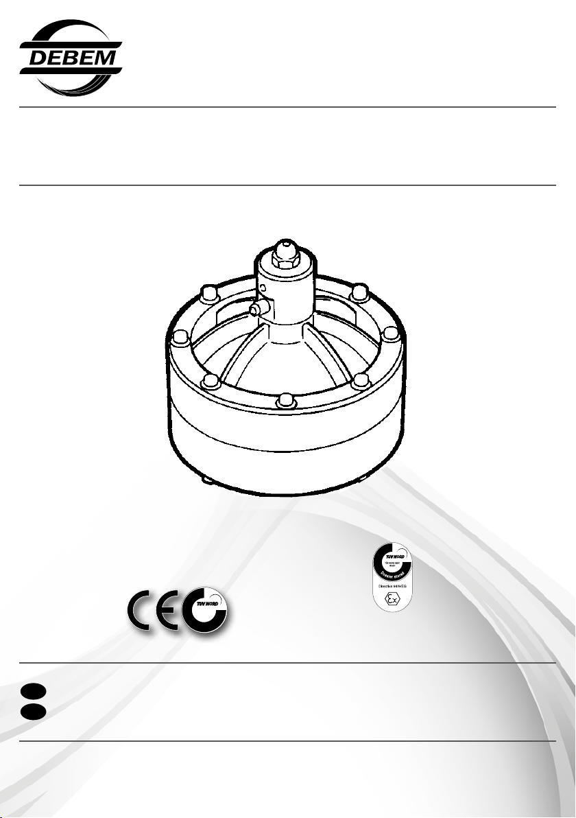
EQUAFLUX 100
MODE
D’EMPLOI
BEDIENUNGS-UND
WARTUNGSANLEITUNGEN
MANUAL DE USO Y
MANTENIMIENTO
INDUSTRIAL PUMPS - INDUSTRIENPUMPEN
petrochemical, food, mechanical, environmental, printing, chemical, painting, galvanic, textile and ceramic, industry
EQUAFLUX
TÜV NORD Italia
S.r.l.
I
1
S
0
O
0
9
D
HINWEISE ZUR VERWENDUNG UND WARTUNG
GB
INSTRUCTIONS FOR USE AND MAINTENANCE
EQUAFLUX 03/2014
Dossier according
to 94/9/EG 8. b II stored
www.debem.it
Page 2

Debem SRL
2014
Alle Rechte der vollständigen oder teilweisen Übersetzung,
des Nachdrucks und der Anpassung auf irgendeine Weise
sind in allen Ländern vorbehalten.
Debem SRL
2014
All rights of total or partial translation, reproduction
and adaptation by any means are reserved
in all countries.
debem.it
2
Page 3

D
INHALT
VORWORT 4
EINFÜHRUNG IN DAS HANDBUCH 4
IDENTIFIKATION DES DÄMPFERS 5
KENNZEICHNUNGEN UND ALLGEMEINE INFORMATIONEN 6
IDENTIFIKATIONSCODE 7
BESCHREIBUNG DES DÄMPFERS 8
TECHNISCHE CHARAKTERISTIKA 10
GARANTIE 12
SICHERHEITSANFORDERUNGEN 13
TRANSPORT UND POSITIONIERUNG 16
ANSCHLUSS DES PRODUKTKREISLAUFS 18
PNEUMATISCHER ANSCHLUSS 20
INBETRIEBNAHME 22
WARTUNG DES PRODUKTKREISLAUFS 24
A- REINIGUNG UND ERSATZ DER MEMBRANEN 26
WARTUNG DES LUFTKREISLAUFS 28
A-ERSATZ DER PNEUMATISCHEN VENTILE 29
FEHLERBEHEBUNG 30
STILLLEGUNG 31
ENTSORGUNG UND RÜCKBAU 31
ERSATZTEILE 32
GB
INDEX
FOREWORD 4
INTRODUCTION 4
DAMPENER IDENTIFICATION 5
MARKINGS AND GENERAL INFORMATION 6
IDENTIFICATION CODES 7
DAMPENER DESCRIPTION 8
TECHNICAL FEATURES 10
WARRANTY 12
SAFETY RULES 13
TRANSPORT AND POSITIONING 16
CONNECTING THE PRODUCT CIRCUIT 18
PNEUMATIC CONNECTION 20
COMMISSIONING 22
PRODUCT CIRCUIT MAINTENANCE 24
A- CLEANING AND REPLACING THE DIAPHRAGMS 26
AIR CIRCUIT MAINTENANCE 28
A- REPLACING THE AIR VALVE 29
TROUBLESHOOTING 30
DECOMMISSIONING 31
DEMOLITION AND DISPOSAL 31
SPARE PARTS 32
SEITE
PAGE
3
debem.it
Page 4
D
VORWORT
Die Pulsationsdämpfer EQUAFLUX wurden in Übereinstimmung mit den Richtlinien 2006/42/EG, 94/9/EWG und 99/92/
EG hergestellt. Die entsprechenden Kriterien der Gebiete
werden in den harmonisierten europäischen Normen EN60079-10 und EN 1127-1 angegeben. Daher stellen sie keine
Gefahren für den Bediener, wenn sie nach den Anweisungen
dieses Handbuchs verwendet werden. Das Handbuch muss
für zukünftiges Nachschlagen des Wartungspersonals in gutem Zustand und/oder in der Nähe der Maschine aufbewahrt
werden. Der Hersteller lehnt jede Haftung für Änderungen,
Manipulationen, falsche Anwendungen oder Arbeiten, die den
Inhalt dieses Handbuchs nicht einhalten und die Schäden an
der Gesundheit und Sicherheit von Personen, Tieren und Gegenständen in der Nähe des Dämpfers verursachen können,
ab. Der Hersteller hofft, dass es Ihnen möglich sein wird, die
FOREWORD
GB
EQUAFLUX pulsation dampeners have been manufactured
tothe 2006/42/CE, 94/9/CEE and 99/92/EC directives.
The relevant area criteria are indicated in the EN-60079-10 and
EN 1127-1harmonized European standards.
Therefore, if used according to the instructions contained in
thismanual, the dampener will not represent any risk to the
operator. This manual must be preserved in good condition
and/oraccompany the machine as reference for maintenance
pur-poses. The manufacturer rejects any liability for any
alteration,modication, incorrect application or operation not
complyingwith the contents of this manual and that may cause
damagethe health and safety of persons, animals or objects
stationingnear the dampener.The Manufacturer trusts you will
EINFÜHRUNG IN DAS HANDBUCH
D
vollen Leistungen der Dämpfer EQUAFLUX zu nutzen. Alle
technischen Angaben beziehen sich auf die Standarddämpfer
EQUAFLUX (siehe “TECHNISCHE CHARAKTERISTIKA“),
aber es wird darauf hingewiesen, dass aufgrund der ständigen Suche nach technologischen Innovationen und Qualität
die angegebenen Charakteristika ohne Vorankündigung geändert werden können. Alle Zeichnungen und Darstellungen
in den mit dem Gerät gelieferten Dokumenten sind Eigentum
des Herstellers, der sich alle Rechte vorbehält und die Weitergabe an Dritte ohne seine vorherige schriftliche Genehmigung
VERBIETET.
ES SIND DAHER ALLE REPRODUKTIONEN, AUCH TEILWEISE, DES HANDBUCHS, DES TEXTES UND DER
ZEICHNUNGEN STRENGSTENS VERBOTEN.
be able to make full use of theperformances offered by the
EQUAFLUX dampeners.All the technical values refer to the
standard version of theEQUAFLUX dampeners (please see
“TECHNICAL FEATURES”). However, our continuous search
for innovation and improve-ments in the technological quality
mean that some of the featuresmay change without notice.
All drawings and any other represen-tation in the documents
supplied with the device are property ofthe Manufacturer who
reserves all rights and FORBIDS distribution to third parties
without his authorization in writing.
THEREFORE REPRODUCTION, EVEN PARTIAL, OF
THISMANUAL, TEXT OR DRAWINGS ARE STRICTLY
FORBIDDEN.
Das vorliegende Handbuch ist integraler Bestandteil des
Pulsationsdämpfers und stellt eine SICHERHEITSEINRICHTUNG. Es enthält wichtige Informationen, die dem Käufer und
seinen Mitarbeitern helfen, den Dämpfer bei der Installation,
Verwendung und Wartung seiner gesamten Lebensdauer in
guten Zustand zu bewahren.
Zu Beginn jedes Kapitels und jedes Abschnitts wurde ein Informationsfeld eingefügt, das dem für die Eingriffe geschultem
Personal durch Symbole die obligatorische persönliche Schutzausrüstung und/oder den Energiestatus des Dämpfers anzeigt.
Jedes Restrisiko, das während des Vorgangs auftreten kann,
wird durch entsprechende Symbole, die im Text integriert sind,
angezeigt. Spezielle Symbole werden auch verwendet, um
besondere Informationen oder Ratschläge bezüglich der Sicherheit und der ordnungsgemäßen Verwendung des Dämpfers
GB
INTRODUCTION
This manual is an integral part of the pulsation dampener,
andrepresents a SAFETY DEVICE. It contains important
informa-tion that will assist the purchaser and his personnel in
installing, using and servicing the dampener in good condition
and safety during service life.
At the head of every chapter an information eld with symbol
sindicates the personnel who are authorized to perform the
operation described in that page along with the individual
protec-tive devices that must be worn and/or the energetic
state of thedampener.
Any residual risk that may occur during these operations
ishighlighted by special symbols embedded in the text.Special
symbols are also used to highlight and differentiate anyparticular
debem.it
hervorzuheben und zu differenzieren.
FÜR ALLE WEITEREN INFORMATIONEN BEZÜGLICH DES
INHALTS DIESES HANDBUCHS KONTAKTIEREN SIE BITTE
DEN KUNDENSERVICE DES HERSTELLERS.
ACHTUNG: dieses Zeichen zeigt dem verantwortlichen Personal an, dass der beschriebene
!
Vorgang ein Expositionsrisiko mit Restgefahren
mit der Möglichkeit von gesundheitlichen Schäden oder
Verletzungen birgt, wenn die beschriebenen Verfahren
und Anforderungen nicht in Übereinstimmung gemäß den
Sicherheitsvorschriften ausgeführt werden.
information or suggestion concerning safety and cor-rect use.
PLEASE CONTACT THE MANUFACTURER’S
CUSTOMER ASSISTANCE DEPARTMENT FOR
!
ANY FURTHER INFORMATION REGARDING THE
CONTENTS OF THIS MANUAL.
WARNING: this sign warns the personnel involved that
failure to perform the operation described in compliance
with the procedures and prescriptions related to safety
regulations entails residual risks that may cause damage
to health or injuries.
4
Page 5
divieto di
usare amme
libere
divieto di
fumare
inserire qui matricola
Il codice identificativo * che compare alla
voce “TIPO” della matricola specifica la
composizione ed i materiali costruttivi
della pompa al fine di determinare
l’idoneità con il prodotto che si desidera
pompare.
Identification code * on the plate against
the “TYPE” heading specifies the compo-
sition and the materials used to build the
pump. This data will help ascertain
whether the pump is suitable for the prod-
uct to be pumped.
Le code d’identification * affiché à la rubri-
que “TYPE” de la plaque indique la com-
position et les matériaux de construction
de la pompe pour déterminer son adapta-
tion au produit à pomper.
Der Identifikationsschlüssel, der unter
„TYP“ des Matrikelschildes erscheint, gibt
die Zusammensetzung und die
Konstruktionsmaterialien der Pumpe an,
um die Eignung für das Produkt, das
gepumpt werden soll, zu bestimmen.
STANDARD
D
HINWEIS: dieses Zeichen zeigt dem verantwortlichen
Personal, das der beschriebene Vorgang Schäden an
der Maschine und/oder ihren Komponenten und folglich
Risiken für den Bediener und/oder die Umwelt verursachen kann,
wenn er nicht in Übereinstimmung gemäß den Sicherheitsvorschriften ausgeführt wird.
ANMERKUNG: dieses Zeichen liefert Informationen
über den laufenden Betrieb, deren Inhalt von relevanter
Bedeutung ist.
SYMBOLE DER OBLIGATORISCHEN UND PERSÖNLICHEN SCHUTZAUSRÜSTUNG: dieses Zeichen zeigt die
Picht zum Tragen angemessener persönlicher Schutzausrüstung und den Energiestatus aufgrund der Gefahren, die
beim Betrieb auftreten können, an.
BEDIENER: diese Qualikation setzt umfassende Kennt-
nisse und volles Verständnis der in der Bedienungsanleitung des Herstellers enthaltenen Informationen sowie
GB
CAUTION: This sign informs involved personnel that
failure to perform the described operation in compli-
ance with safety regulations may cause damage to
the machine
and/or its components hence risks for the operator and/or the
environment.
REMARK: This sign provides information regarding the
current operation and its contents are very important.
INSTALLER AND MECHANICAL SERVICEMAN:
This function entails full knowledge and understanding
of information contained in the user manual issued
by the manufacturer, specic expertise in installation and
ordinary maintenance tasks as well as specic skills related
to the sector of use.
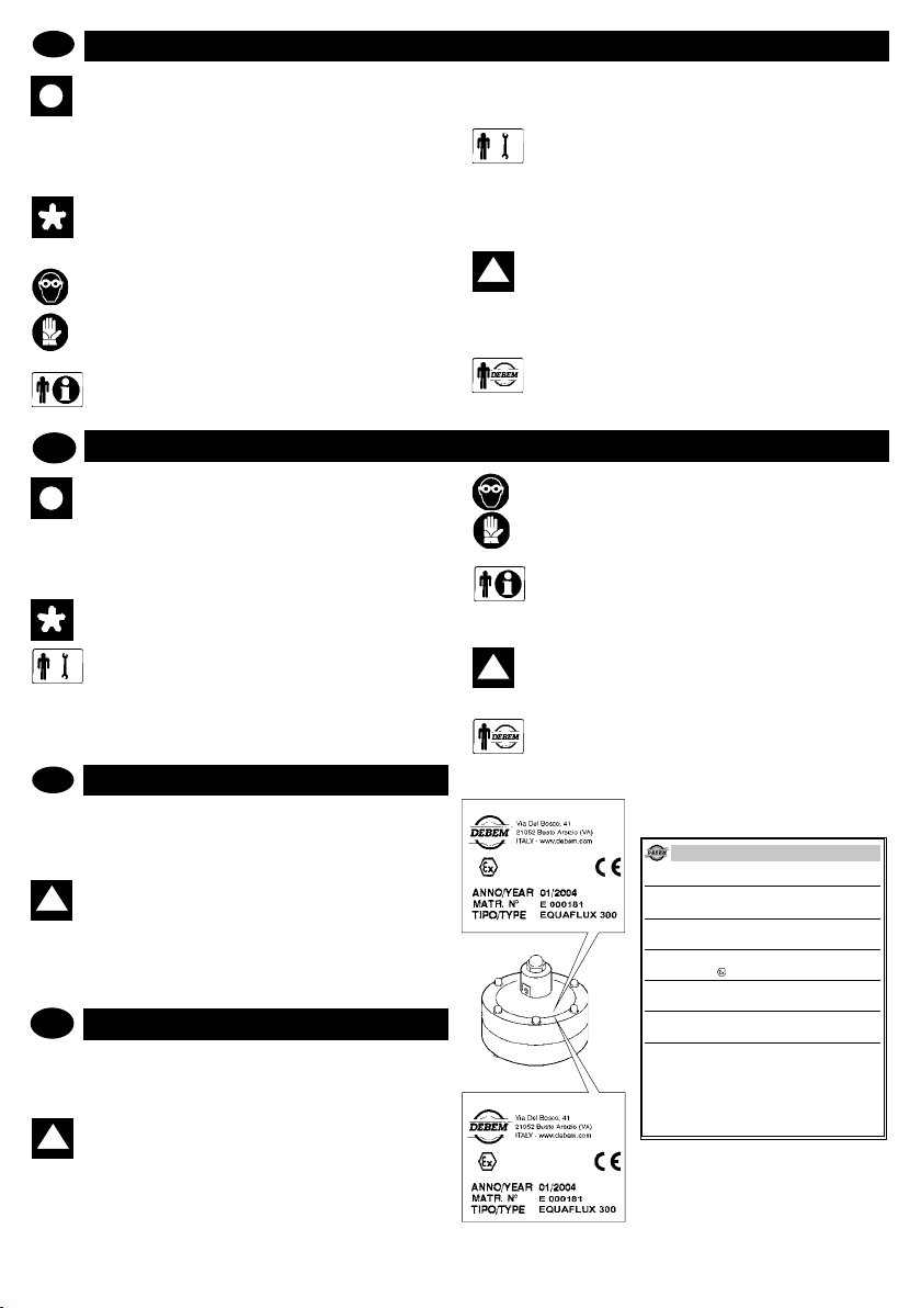
IDENTIFIKATION DES DÄMPFERS
D
Jeder Pulsationsdämpfer ist mit einem Typenschild ausgestattet,
das die Spezikationen und das Baumaterial angibt. Bei jeglicher
Kommunikation mit dem Hersteller, dem Händler oder den autorisierten Kundenzentren sind diese Daten anzugeben.
ACHTUNG: es ist verboten, das Typenschild der Pumpe und/oder die auf dem Typenschild angegebenen
!
Daten zu entfernen und/oder zu verändern.
Der Identikationscode *, der unter dem Punkt “TYP” des Typenschilds erscheint, speziziert die Zusammensetzung und das
Baumaterial der Pumpe, um die Eignung mit dem Produkt, das
gepumpt werden soll, zu bestimmen.
GB
DAMPNER IDENTIFICATION
Each dampener has an identication plate carrying its specication details and materials. Always refer to this data when
contacting the manufacturer, dealer or customer service centers.
WARNING: removing or altering this identication
!
plate and or the data it contains is forbidden.
Identication code * on the plate against the “TYPE” heading
species the composition and the materials used to build the
pump. This data will help ascertain whether the pump is suitable
for the product to be pumped.
spezische Fähigkeiten in Bezug auf den Anwendungsbereich
voraus.
INSTALLATIONS- UND WARTUNGSPERSONAL:
diese Qualikation setzt umfassende Kenntnisse und
volles Verständnis der in der Bedienungsanleitung des
Herstellers enthaltenen Informationen, spezisches Fachwissen
bei der Installation und gewöhnlichen Wartung sowie spezische
Fähigkeiten in Bezug auf den Anwendungsbereich voraus.
ACHTUNG: das für die Installation, Inspektion und
!
Wartung der Pumpe verantwortliche Personal muss
über eine angemessene technische Ausbildung mit
ausreichenden Kenntnissen über explosionsgefährdete Bereiche und die damit verbundenen Risiken verfügen.
AUSSERORDENTLICHE VERFAHREN: identiziert
die Eingriffe, die den Technikern des Kundenservices
vorbehalten sind und ausschließlich in der Werkstatt des
Herstellers durchgeführt werden.
COMPULSORY AND INDIVIDUAL PROTECTION
SIGNS: These signs indicate that proper individual pro-
tection must also be used against energetic events because of the dangers that may arise during the operation.
OPERATOR: this function entails full knowledge and
understanding of the information contained in the user
manual issued by the Manufacturer as well as specic
skills related to the sector of use.
WARNING The personnel in charge of installing,
!
testing and servicing the pump must have a suitable
technical knowledge of potentially explosive
atmospheres and of the relevant risks.
EXTRAORDINARY PROCEDURES: Identies opera-
tions that can only be performed by the after-sales
service technicians at the Manufacturer’s premises.
CONDUCT
II 2/2 GD c IIB T135°C
II 3/3 GD c IIB T135°C
STANDARD
5
EQUAFLUX STANDARD
DICHIARAZIONE DI CONFORMITA’
DECLARATION DE CONFORMITE - DECLARACION DE CONFORMIDAD
ERKLÄRUNG BEZÜGLICH EINHALTUNG DER VORSCHRIFTEN - DECLARATION OF CONFORMITY
DEBEM SRL - Via del bosco 41 - 21052 Busto Arsizio (VA) - ITALIA
Questo prodotto è conforme alle seguenti direttive CE/EX e relativi standard armonizzati:
This product complies with the following European Community Directives CE/EX and relating harmonized standards:
Ce produit est conforme aux directives de la Communautè europèenne suivantes CE/EX et les normes correspondantes harmonisées:
Este producto cumple con las siguientes Directrices de la Comunidad Europea CE/EX y relativas normas armonizadas:
Dieses Produkt erfüllt die folgenden Vorschriften der Europäischen Gemeinschaft CE/EXund entsprechende harmonisierte Normen:
2006/42/CE Direttiva Macchine / Machinery Directive / Maschinenrichtlinie / Directive Machines / Directiva Máquinas
94/9/CE: Direttiva ATEX, concernente il ravvicinamento delle legislazioni degli Stati Membri relative agli apparecchi e sistemi di protezione destinati a essere utilizzati in
atmosfera potenzialmente esplosiva.
94/9/EC: ATEX Directive, on the approximation of European Member States laws concerning protection equipments and systems to be used in potentially explosive environments.
94/9/CE : Directive ATEX, concernant le rapprochement des législations des états-membres relatives aux appareils et aux dispositifs de protection utilisés en environnement potentiellement explosif.
94/9 CE: ATEX Richtlinie über die Angleichung der Rechtsvorschriften der Mitgliedstaaten für Geräte und Schutzsysteme zur bestimmungsgemäßen Verwendung in explosionsgefährdeten Bereichen.
94/9/CE: Directiva ATEX, relativa el acercamiento de las legislaciones de los Estados Miembros relativas a los aparatos y sistemas de protección destinados a ser uti-
FABBRICATO DA:
FABRIQUE PAR - FABRICADA POR - HERGESTELLT VON - MANUFACTURED BY
TIPO/SERIE
TYPE / SERIE- TIPO / SERIE - TYP / SERIE - TYPE / SERIES
inserire qui tipo/serie
MARCATURA ATEX
MARKING ATEX - MARQUAGE ATEX - MARKIERUNG ATEX - MARCAR ATEX
II 3/3 GD c IIB T135ºC
MODELLO
MODELE - MODELO - MODELL - MODEL
inserire qui modello
CODICE
CODE - CODE - KODE - CODICE
inserire qui codice
MATRICOLA
SERIAL NUMBER - MATRICULE - MATRIKELNUMMER - MATRICULA
debem.it
Page 6

D
KENNZEICHNUNG UND ALLGEMEINE INFORMATIONEN
Die Dämpfer EQUAFLUX in Übereinstimmung mit der Richtlinie
94/9/EWG tragen die folgende Kennzeichnung:
II 2/2 GD c IIB T135°C
: Sicherheitssymbol in Übereinstimmung mit DIN 40012
Anhang A.
II 2/2 GD: Oberirdische Anlage für die Verwendung in Bereichen
mit Vorhandensein von Gas, Dämpfen oder Nebel sowie Wolken aus brennbarem Staub in der Luft, die gelegentlich beim
Normalbetrieb, sowohl im Außen- als auch im Innenbereich,
auftreten (ZONE 1).
c: Geräteschutz durch konstruktive Sicherheit (EN 13463-5).
Die Dämpfer EQUAFLUX in Übereinstimmung mit der Richtlinie
94/9/CEE tragen die folgende Kennzeichnung:
II 3/3 GD c IIB T135°C
: Sicherheitssymbol in Übereinstimmung mit DIN 40012
Anhang A.
II 3/3GD: Oberirdische Anlage für die Verwendung in Bereichen in
denen das Vorhandensein von Gas, Dämpfen oder Nebel sowie
Wolken aus brennbarem Staub in der Luft beim Normalbetrieb,
sowohl im Außen- als auch im Innenbereich, unwahrscheinlich
oder für kurze Zeiträume selten ist (ZONE 2).
c: Geräteschutz durch konstruktive Sicherheit (EN 13463-5).
MARKINGS AND GENERAL INFORMATION
GB
In compliance with the 94/9/CEE standards, the EQUAFLUX
pulsation dampeners carry the following identication marks:
II 2/2 GD c IIB T135°C
: safety symbol to Din 40012 attachment A.
II 2/2GD: surface equipment for use in areas with the presence
of gases, vapors or mists in addition to clouds of combustible
dust in the air that occur occasionally during normal operation (EN 1127-1 par. 6.3), both in external and internal areas
(ZONE 1).
IIB: mit Ausnahme der folgenden Produkte: Wasserstoff, Acetylen, Schwefelkohlenstoff.
T135°C: Klasse der zugelassenen Temperaturen. Der Anwender muss Fluide bei einer Temperatur innerhalb dieser
Klassikation verarbeiten. Dabei sind die in diesem Handbuch
wiedergegebenen Anweisungen und die gesetzlich geltenden
Bestimmungen zu berücksichtigen. Weiterhin muss der Anwender die Zündtemperaturen der Gase, Dämpfe oder Nebel
sowie der brennbaren in der Luft des Anwendungsbereichs
vorhandenen Stäube berücksichtigen.
Das technische Datenblatt ist beim TÜV NORD CERT in
Hannover hinterlegt.
IIB: mit Ausnahme der folgenden Produkte: Wasserstoff, Acetylen,
Schwefelkohlenstoff.
T135°C: Klasse der zugelassenen Temperaturen. Der Anwender
muss Fluide bei einer Temperatur innerhalb dieser Klassikation
verarbeiten. Dabei sind die in diesem Handbuch wiedergegebenen
Anweisungen und die gesetzlich geltenden Bestimmungen zu berücksichtigen. Weiterhin muss der Anwender die Zündtemperaturen der Gase, Dämpfe oder Nebel sowie der brennbaren in der Luft
des Anwendungsbereichs vorhandenen Stäube berücksichtigen.
Das technische Datenblatt ist beim TÜV NORD CERT in
Hannover hinterlegt.
c: protection by constructional safety (EN 13463-5).
IIB: Excluding the following products hydrogen, acetylene,
carbon disulphide.
T135°C: Class of admitted temperatures. The processed uid
temperature value must fall within such class range and the
user must comply with the instructions contained in the manual
and with the current laws. Furthermore, the user must take
into account the ignition point of the gases, vapors and mists
in addition to clouds of combustible powder in the air existing
in the area of use.
The technical sheet is deposited with TÜV NORD CERT
Hanover.
In compliance with the 94/9/CEE standards, the EQUAFLUX
pulsation dampeners carry the following identication marks:
II 3/3 GD c IIB T135°C
: safety symbol to Din 40012 attachment A.
II 3/3GD: surface equipment used in areas where the presence
of gas, vapors or mists in addition to clouds of combustible
powder in the air is unlikely during normal operation both in
external and internal areas and, if it does occur, it will only
persist for a short period (ZONE 2).
debem.it
c: protection by constructional safety (EN 13463-5).
IIB: Excluding the following products: hydrogen, acetylene,
carbon disulphide.
T135°C: Class of admitted temperatures. The processed uid
temperature value must fall within such class range and the
user must comply with the instructions contained in the manual
and with the current laws. Furthermore, the user must take
into account the ignition point of the gases, vapors and mists
in addition to clouds of combustible powder in the air existing
in the area of use.
The technical sheet is deposited with TÜV NORD CERT
Hanover.
6
Page 7
D
IDENTIFIKATIONSCODE
EQ51-
DÄMPFER
EQ51 - Equaux 51
EQ100 - Equaux100
EQ200 - Equaux200
EQ302 - Equaux302
EQ303 - Equaux303
FQ 51 - Foodequaux 51
FQ 100 - Foodequaux 100
FQ 200 - Foodequaux 200
FQ 302 - Foodequaux 302
GB
IDENTIFICATION CODE
DÄMPFERKÖRPER
P - Polypropylen
FC - PVDF+CF
R - PPS-V
A - Aisi 316 (außer EQ 303)
AL - Aluminium
PC - PP + CF
A - Aisi 316
EQ51-
DUMPNER MODEL
EQ51 - Equaux 51
EQ100 - Equaux100
EQ200 - Equaux200
EQ302 - Equaux302
EQ303 - Equaux303
FQ 51 - Foodequaux 51
FQ 100 - Foodequaux 100
FQ 200 - Foodequaux200
FQ 302 - Foodequaux 302
DAMPNER BODY
P - polypropylene
FC - PVDF+CF
R - PPS-V
A - Aisi 316 (except EQ 303)
AL - Alu
PC - PP + CF
A - Aisi 316
P-
P-
H T C
MEMBRAN
LUFTSEITE
H = Hytrel
M = Santoprene
H = Hytrel
MEMBRAN
FLUIDSEITE
T = PTFE
T = PTFE
H T C
DAPHRAGMS
AIR SIDE
H = Hytrel
M = Santoprene
H = Hytrel
DIAPHRAGMS
FLUID SIDE
T = PTFE
T = PTFE
CONDUCT
AUSFÜHRUNG
(zone 1)
II 2/2 GD c IIB T135°C
C = bei Bedarf
(zone 1)
II 2/2 GD c IIB T135°C
C = bei Bedarf
CONDUCT
VERSION
(zona 1)
II 2/2 GD c IIB T135°C
C = if required
(zona 1)
II 2/2 GD c IIB T135°C
C = if required
7
debem.it
Page 8
D
BESCHREIBUNG DES DÄMPFERS
Verwendungszweck
Die Dämpfer EQUAFLUX wurden entworfen und gebaut, um
automatisch die Schwankungen von Förderhöhe und Leistung
hinter der pneumatischen Membranpumpe für Flüssigkeiten
aus chemisch, mit den Baukomponenten kompatiblen Material, zu dämpfen. Der Betrieb des Dämpfers ist bei Betriebstemperaturen von +3°C bis zu einem Maximum von 60/95°C in
Abhängigkeit von der Art der Zusammensetzung des Materials des Dämpfers, der Temperaturklasse und der Art des
Fluids erlaubt. Die maximale zulässige Temperatur für Pro-
zessuide oder –stäube ist allerdings durch das Material des
Dämpfers abhängig und/oder herabgestuft; bei Überschreitung ist die Einhaltung der maximalen Temperatur, die auf der
Kennzeichnung angegeben ist, nicht gewährleistet.
TEMPERATURKLASSE FÜR PUMPEN IN EXPLOSIONS-
Im Folgenden wird die Formel, um die maximal zulässige
Temperatur des Prozessuids für die Dämpfer in CONDUCT-
Ausführung zu bestimmen, wiedergegeben. ( II 2/2 GD c
IIB T135°C).
NUR FÜR PUMPEN, DIE IN ZONE 1 INSTALLIERT WERDEN.
TEMPRA-
TURKLASSE
ATEX
T4 Tx Tf
135°C 55°C
GB
DAMPNER DESCRIPTION
Proper use
EQUAFLUX dampeners are designed and constructed to automatically reduce head and delivery variation occurring down-
stream to pneumatic diaphragm pumps used to pump uids
compatible with their components.The dampener must operate
with a working temperature ranging from +3° C up to a maximum
of 60/95° C in relation to the material of the components.
The use
is in accordance with the type of material that the dampener is
composed of, the temperature class and the type of uid. In any
case, the maximum temperature allowed for the process uid or
powder depends on and/or is declassed by the material of the
dampener; if exceeded, respect of the maximum temperature
displayed on the marking is not guaranteed.
FATTORE DI
CALCOLO
(solo per ZONA 1)
- =
- =
MASSIMA
TEMPERATURA
DI PROCESSO
DEL FLUIDO
95°C
GEFÄHRTDETEN BEREICHEN (Bereich 1) Die Klasse der
Bezugstemperatur für den Schutz vor Explosionsrisiken der
Dämpfer für den Einsatz in explosionsgefährdeten Bereichen
liegt bei T135°C (T4); im Folgenden werden die Daten und
zugelassenen Einsatzbedingungen wiedergegeben:
DEFINITION DER BERECHNUNGSDATEN:
T4 = Temperaturklasse ATEX 135°C
Ta = maximale Umgebungstemperatur 40°C;
Tl = maximale Temperatur für den Trockenlauf der Pumpe im
Arbeitsbereich (50°C);
Δs = Sicherheitsfaktor (5°C);
Tx = Berechnungsfaktor (Tl + Δs) nur für ZONE 1;
Tf = maximal zulässige Temperatur des Prozessuids.
ACHTUNG: in Anbetracht der Variationsbreite der
!
zulässigen Temperatur in Zone 1 erlauben Pro-
zesstemperaturen des Fluids über den oben angegebenen Werten nicht die Einhaltung der entsprechenden
Temperaturklassen T4 (135°C) für explosionsgefährdete
Umgebungen. Zudem können sie Schäden am Dämpfer verursachen. Wo der Benutzer das Risiko der Überschreitung
des von diesem Handbuch vorgesehenen Temperaturlimits
vorhersieht, ist es notwendig, an der Anlage eine Schutzvorrichtung zu installieren, die das Erreichen der maximal
zulässigen Temperatur des Prozessuids verhindert. Die
maximale Temperatur des Geräts wurde ohne Staubablage-
rung auf den äußeren und inneren Oberächen festgelegt.
TEMPERATURE CLASSES FOR PUMPS TO BE INSTALLED
IN AN EXPLOSIVE ENVIRONMENT (ZONE 1): T135°C (T4) is
the class of temperature corresponding to the protection against
the risk of explosion of the dampeners designed for use in
explosive atmospheres; the data and permitted operational
conditions are indicated here below:
DEFINITION OF THE CALCULATION DATA
• T4 = ATEX temperature class 135°C
• Ta = maximum ambient temperature 40°C;
• Tl = maximum temperature for dry use of the dampener in
the workplace (50°C);
• s = safety factor (5°C);
• Tx = calculation factor (Tl + s) only for ZONE 1;
• Tf = maximum admitted temperature for uid processing.
The formula for dening the maximum allowed uidprocessing
temperature for CONDUCT version dampeners ( II 2/2GD
c IIB T135°C) is shown here below.
ONLY FOR PUMPS TO BE INSTALLED IN ZONE 1.
ATEX
TEMPERATURE
CLASS
T4 Tx Tf
135°C 55°C
CALCULATION
FACTOR
(only for ZONE 1)
- =
- =
MAXIMUM
FLUID
PROCESSING
TEMPERATURE
95°C
debem.it
WARNING: In consideration of the admitted
ambient temperature variation range, uid service
!
temperature values higher than those indicated
above will not permit compliance to the corresponding T4
temperature classes for potentially explosive enviroments.
Where the user presumes that the temperature limits set
forthin this manual may be exceeded, a protective device
must be installed on the system that prevents the maximum
allowed uid processing temperature from being reached.
The equipment’s maximum temperature has been dened
without deposits of dust on external and internal surfaces.
8
Page 9
D
Funktionsprinzip
Die durch die Pulsierung des durch die nachgeschaltete pneumatische Pumpe gepumpten Produkts bewegte Membran des
Dämpfers bestimmt den automatischen Eingriff des Pneumatikventils des Dämpfers, das, dank einer Produktkammer mit
einer für den Pumpentyp geeigneten Kapazität in der Lage ist,
die Schwankungen der Förderhöhe und/oder Leistung auszugleichen. Die Frequenz und die Förderhöhe sind automatisch
selbstregulierend ohne Eingriff oder Einstellung in Abhängigkeit
der realen Bedürfnisse des Produktkreislaufs, wodurch schädliche Wasserschläge reduziert und Vibrationen minimiert werden.
Somit werden andere Geräte auf derselben Leitung geschützt.
Unsachgemäße Verwendung
ACHTUNG: jede Verwendung der Dämpfer für
!
anderweitige Nutzungen als die zuvor im Kapitel
“TECHNISCHE DATEN” beschriebene und erläuterte, wird als unsachgemäße Verwendung betrachtet und ist
daher vom Unternehmen Debem verboten.
Insbesondere IST die Verwendung der Dämpfer EQUAFLUX
für Folgendes VERBOTEN:
- die Verwendung mit zu pumpenden chemisch nicht mit den
Baumaterialien kompatiblen Flüssigkeiten;
- die Verwendung mit Produkten, deren spezisches Gewicht
über dem der Flüssigkeit (z.B. Wasser mit Sand) liegt;
- mit Luftdrücken, Temperaturen und Produkteigenschaften, die
in Widerspruch zu den technischen Daten stehen.
ACHTUNG: aufgrund der unendlichen Vielfalt von
Produkten und chemischen Zusammensetzungen
!
wird der Benutzer gehalten, über beste Kenntnisse
der Reaktionen und Kompatibilität mit den Baumaterialien
des Dämpfers zu verfügen. Daher müssen vor der Anwendung fachmännisch alle notwendigen Inspektionen und
Tests ausgeführt werden, um auch die geringsten Risiken
zu vermeiden, die der Hersteller nicht voraussehen und für
die er nicht verantwortlich gemacht werden kann.
ACHTUNG: Der Benutzer muss das Verhältnis zwi-
!
schen der maximalen Oberächentemperatur des
Dämpfers, die auf der Kennzeichnung angegeben
ist und der minimalen Zündtemperatur der Staubschichten
und der Staubwolken, wie in der EN1227-1 angegeben,
bewerten.
GB
Functioning principles
The product pulsation caused by the pneumatic pump moves
the dampener diaphragm which in turn causes the dampener
air valve to step in. A product chamber suitably dimensioned to
the pump type compensates the head and/or delivery changes.
The head frequency and capacity are automatically adjusted
without any intervention or set up according to the actual product
circuit requirements. This reduces dangerous waterhammer
effects and vibration therefore protecting other equipment on
the same line.
Improper use
WARNING: use of a dampeners for any other use
!
otherthan that previously described IN THE CHAP-
WARNING: since an endless variety of products
andchemical compositions exist, the user is
! !
presumed tohave the best knowledge of their
reaction and compatibilitywith the materials used to build
the dampener. Therefore,before using the dampener, all
the necessary checks andtests must be performed with
great care to avoid even theslightest risk, an event that
the manufacturer cannotforesee and for which he cannot
be held responsible.
WARNING: the user must evaluate the ratio be-
tweenthe maximum surface temperature of the
!
dampenerindicated in the marking and the minimum ignition temperature of the layers of powder and the
clouds ofpowder as indicated in the EN1227-1
9
ACHTUNG: jede Verwendung des Dämpfers entgegen den im Bedienungshandbuch und in der
!
Wartungsanleitung angegebenen Anweisungen
führt zum Erlöschen der Sicherheitsanforderungen und
der Anforderungen zum Schutz vor Explosionsgefahr. Es
wurden die Risiken in Zusammenhang mit der Verwendung
des Dämpfers unter den genauen im Bedienungshandbuch
und der Wartungsanleitung vorgeschriebenen Bedingungen analysiert: die Analyse der Risiken in Zusammenhang
mit der Schnittstelle mit anderen Systemkomponenten
muss vom Installateur durchgeführt werden.
ATEX- Verordnung: Der Benutzers ist verantwortlich
!
für die Klassizierung des Einsatzgebietes Anwen-
dung des Benutzers des Geräts. Die Identikation
der Gerätekategorie liegt hingegen beim Hersteller.
TER EN-TITLED “TECHNICAL CHARACTERISTICS” is to be
considered improper use of the dampener and is therefore
forbidden by Debem.
In particular, it is FORBIDDEN to use EQUAFLUX dampeners for:
- operation with liquids that are chemically incompatible withthe
materials of construction;
- operation with suspended products whose specic weight
is higher than the liquid’s (for example with water and sand);
- con pressioni pneumatiche, temperature e caratteristiche del
prodotto in disaccordo con i dati tecnici.
WARNING. Use of the dampener that does not
complywith the instructions indicated in the use
and mainte-nance manual will cancel the safety
and explosion protectionrequirements. The risks associated with use of the dampe-ner under the exact conditions
set forth in the use and main-tenance manual have been
analysed, whilst the analysis ofthe risks associated with
the interface with other systemcomponents must be carried
out by the installer.
ATEX: The user is responsible for classifying the
!
area of use whilst identication of the equipment
category is the responsibility of the manufacturer.
debem.it
Page 10

D
45
29
35,5
19
66,5
45
117
ATTACCO
PRODOTTO
3/4" G F
ATTACCO ARIA
PER TUBO
6
183,25
151
100
ATTACCO PRODOTTO 1" G
133
11,5
109
ATTACCO PRODOTTO 1/2" G
50
1" 1/2 G F
ATTACCO ARIA
ATTACCO 2"
398
260
182,4
55
516
ATTACCO ARIA 8 mm
ATTACCO 3"
ATTACCO 3"
330
350
175
ATTACCO 3"
TECHNISCHE CHARAKTERISTIKA
Die angegebenen Abmessungen und Daten beziehen sich auf Standardausführungen und können aufgrund der technischen/innovativen Entwicklung im Laufe der Zeit ohne vorherige Ankündigung geändert werden.
TECHNICAL FEATURES
GB
Dimensions and characteristics mentioned in this manual referto standard products and may vary without notice as a consequence of technical improvements.
EQUAFLUX 51
PLASTIK/PLASTIC
EQUAFLUX 200
PLASTIK/PLASTIC
60
283,2
45 114,7 123,5
59
254
EQUAFLUX 302
PLASTIK/PLASTIC
ANSCHLUSS
LUFTANSCHLUSS
PRODUKT
ANSCHLUSS
LUFTANSCHLUSS
ATTACCO ARIA
6
PER TUBO
PRODUKT
ATTACCO
ANSCHLUSS
PRODOTTO
516
EQUAFLUX 51 AISI 316
FOODEQUAFLUX 51
66,5
ATTACCO PRODOTTO 1/2" G
PRODUKTANSCHLUSS
EQUAFLUX 200 AISI 316
FOODEQUAFLUX 200
65
PRODUKTANSCHLUSS
ATTACCO 2"
ANSCHLUSS
78,50
104,70
44
ATTACCO PRODOTTO 1" G F
175
260
ANSCHLUSS
350
117
45
120
LUFTANSCHLUSS
12,50
R
ATTACCO 2"
LUFTANSCHLUSS
ATTACCO ARIA
PER TUBO
29
PER TUBO 6
264,70
68,70
EQUAFLUX 100
PLASTIK/PLASTIC
352
LUFTANSCHLUSS
46
170
6
46
30,5
79
177
83
15
PRODUKT
ATTACCO
ANSCHLUSS
PRODOTTO 1" G F
EQUAFLUX 302 METAL/METAL
FOODEQUAFLUX 302
ANSCHLUSS
ATTACCO 2"
ATTACCO ARIA
PER TUBO
ANSCHLUSS
EQUAFLUX 100 AISI 316
FOODEQUAFLUX 100
6
29
81,5 23,25 79
ATTACCO PRODOTTO 1" G
PRODUKTANSCHLUSS
ATTACCO 2"
50
72
170
175
LUFTANSCHLUSS
ATTACCO ARIA
PER TUBO
TUYAU
29
ATTACCO 2"
ANSCHLUSS
350
6
EQUAFLUX 303
PLASTIK/PLASTIC
ANSCHLUSS
LUFTANSCHLUSS
debem.it
ATTACCO ARIA 8 mm
LUFTANSCHLUSS
per tubo ø 8 mm
per tubo ø 8 mm
260
182,4
55
398
ANSCHLUSS
330
ATTACCO ARIA 1/4" G
LUFTANSCHLUSS
per tubo ø 8 mm
EQUAFLUX 303
ALU
ANSCHLUSS
ATTACCO 2"
per tubo ø 8 mm
ATTACCO ARIA 1/4" G
LUFTANSCHLUSS
10
3”
352
ANSCHLUSS
260
182,4
55
ATTACCO 2"
ANSCHLUSS
182,4
55
260
107
312
356
ATTACCO 2"
ANSCHLUSS
3”
107
312
356
350
175
Page 11
FQ 302
FOODBOXER 502
FQ 200
FOODBOXER 100
FOODBOXER 150
FQ 100
FOODBOXER 50
FOODBOXER 80
FOODBOXER 251
32
FQ 302
FOODBOXER 502
FQ 200
FOODBOXER 100
FOODBOXER 150
FOODBOXER 251
FQ 100
FOODBOXER 50
FOODBOXER 80
32
FQ 51
FOODBOXER 30
BOXER 503
EQUAFLUX 303
BOXER 502
BOXER 522
EQUAFLUX 302
BOXER 150
BOXER 250/251
EQUAFLUX 200
BOXER 100
BOXER 80/81
EQUAFLUX 100
MINIBOXER/B50
CUBIC15
MIDGETBOX
MICROBOXER
EQUAFLUX 51
Maßeinheiten
G 1/8” G 1” G 1 1/2” G 2”/G 3” G 2”/G 3” G 1/8” G 1” G 1 1/2” G 2”/G 3”
Inch
95 95 95 95
EQ 51
FOODBOXER 30
65
95
65
95
95
95
23
35
29
28,5
BOXER 503
EQUAFLUX 303
65
95
65
95
95
95
23
32
26
28,5
BOXER 502
BOXER 522
EQUAFLUX 302
65
95
65
95
95
95
3,8
4,5
4,5
BOXER 150
BOXER 250/251
EQUAFLUX 200
65
95
65
95
95
95
1,5
1,7
1,7
BOXER 100
BOXER 80/81
EQUAFLUX 100
MINIBOXER/B50
65
95
65
95
95
95
0,5
0,5
0,6
G 1/8” G 1” G 1 1/2” G 2”/G 3” G 2”/G 3” G 1/8” G 1” G 1 1/2” G 2”/G 3”
CUBIC15
MIDGETBOX
MICROBOXER
EQUAFLUX 51
°C
Kg
unit
inches
65
95
65
95
65
95
65
95
65
95
95 95 95 95
65
95
95
95
23
35
29
28,5
65
95
95
95
23
32
26
28,5
65
95
95
95
3,8
4,5
4,5
65
95
95
95
1,5
1,7
1,7
65
95
95
95
0,5
0,5
0,6
°C
Kg
TECHNISCHE
DATEN
D
Anschlüsse des Produkts
Anschluss Luft - Leitung Øi 4 - Øe 6 Øi 4 - Øe 6 Øi 6 - Øe 8 Øi 6 - Øe 8 Øi 6 - Øe 8 Øi 4 - Øe 6 Øi 4 - Øe 6 Øi 6 - Øe 8 Øi 6 - Øe 8
Schwankung der Förderhöhe, min - max mt. 10 ÷ 70 10 ÷ 70 10 ÷ 70 10 ÷ 70 10 ÷ 70 10 ÷ 70 10 ÷ 70 10 ÷ 70 10 ÷ 70
Luftdruck, min - max bar 2 ÷ 7 2 ÷ 7 2 ÷ 7 2 ÷ 7 2 ÷ 7 2 ÷ 7 2 ÷ 7 2 ÷ 7 2 ÷ 7
PP+CF (zona 1)
PVDF + CF (zona 1)
PP (zona 2)
PPS-V / PVDF
(zona 2)
max. Temperatur
Aisi 316
Alu
PP
PVDF
PPS-V
Aisi 316
Nettogewicht
Alu
TECHNICAL
GB
11
DATA
Product tting
Air tting - tube Øi 4 - Øe 6 Øi 4 - Øe 6 Øi 6 - Øe 8 Øi 6 - Øe 8 Øi 6 - Øe 8 Øi 4 - Øe 6 Øi 4 - Øe 6 Øi 6 - Øe 8 Øi 6 - Øe 8
Head change, min - max mt. 10 ÷ 70 10 ÷ 70 10 ÷ 70 10 ÷ 70 10 ÷ 70 10 ÷ 70 10 ÷ 70 10 ÷ 70 10 ÷ 70
PP+CF (zona 1)
PVDF + CF (zone
1)
Air pressure, min - max bar 2 ÷ 7 2 ÷ 7 2 ÷ 7 2 ÷ 7 2 ÷ 7 2 ÷ 7 2 ÷ 7 2 ÷ 7 2 ÷ 7
PP (zone 2)
PPS-V / PVDF
(zona 2)
Aisi 316
Alu
Max temperature
PP
PVDF
PPS-V
Aisi 316
Net weight
debem.it
Alu
Page 12

D
GARANTIE
Die Pulsationsdämpfer EQUAFLUX sind hochwertige Produk-
te, die bei den Endbenutzern vollsten Anklang nden.
Sollte ein Fehler auftreten, ist der KUNDENSERVICE des
HERSTELLERS, der Händler oder das Service-Center in Ihrer Nähe zu kontaktieren. So schnell wie möglich erhalten Sie
Unterstützung.
In jedem Fall geben Sie bitte folgende Informationen an:
A- die vollständige Adresse
B- die Kennzeichnung des Dämpfers
C- die Schutzklasse gegen das Explosionsrisiko
D- die Beschreibung der Fehlstörung
Alle Pulsationsdämpfer EQUAFLUX werden durch folgende
Formel abgedeckt:
1- Der Dämpfer ist für 12 Monate auf alle mechanischen Teile,
die für fehlerhaft befunden werden, garantiert. Die Garantiezeit beginnt mit dem Kaufdatum.
2- Jeder Fehler muss innerhalb von 8 Tagen schriftlich dem
Hersteller mitgeteilt werden.
3- Die Reparatur während der Garantiezeit erfolgt ausschließlich in einer unserer Werkstätten nach Versand oder Zustellung des defekten Dämpfers.
4- Im Falle einer Reparatur oder bei Ersatz von Teilen des
Dämpfers wird die Garantie nicht verlängert.
5- Die fehlerhaften Teile müssen dem Hersteller zurückgegeben werden, der sich das Recht vorbehält, eine Überprüfung
der Teile in seiner eigenen Werkstatt durchzuführen, um den
Fehler oder externe Gründe, die den Schaden verursacht haben könnten, zu ermitteln. Sollten die Teile nicht als fehlerhaft
eingestuft werden, behält sich der Hersteller das Recht vor,
die gesamten Kosten der zuvor unter Garantie ersetzten Teile
in Rechnung zu stellen.
Der Hersteller übernimmt keine Kosten und Risiken für den
Transport der defekten Teile oder der reparierten Teile oder
der Ersatzteile, einschließlich etwaiger Zollgebühren.
Die Reparatur oder der Ersatz der defekten Teile deckt alle
Garantieverpichtungen ab.
Die Garantie umfasst KEINE indirekten Schäden und Fabrikationsfehler.
GB
WARRANTY
The high quality of EQUAFLUX pulsation dampeners is often
conrmed to us by the end users.
However, should any defect appear, please contact the
Manufacturer’s After-Sales Service, your delear or the nearest
Customer Service Center where you will receive assistance as
quickly as possible.
In any case, please provide:
A- Your complete address
B- Dampener identication
C- Explosion risk protection class
D- Anomaly description
5 - Faulty parts must be forwarded to the Manufacturer who
reserves the right to test them in this own factory to identify the
fault or any external reason that may have caused it. Should
the parts be found not faulty, the Manufacturer reserves the
right to invoice the total cost of the parts that had been replaced
under this warranty.
Costs and transportation risks of faulty, repaired or replaced
parts including custom charges will be borne entirely by the
client.
Repair or replacement of faulty parts cover any obligation
under this warranty.
The warranty DOES NOT cover any indirect damage and in
particular any normal consumable material such as diaphragms,
gaskets, and others.
The warranty does not cover parts damaged as a consequence
debem.it
Zudem sind normale Verbrauchsmaterialien wie Membranen,
Dichtungen, usw. von der Garantie ausgeschlossen.
Teile, die aufgrund einer falschen Installation, Nachlässigkeit
oder Fahrlässigkeit bei der Anwendung, unsachgemäßer
Wartung, Transportschäden oder jeglichem Umstand, der
nicht auf Funktionsstörungen oder Verarbeitungsfehler zurückzuführen ist, sind nicht von der Garantie abgedeckt.
Die Garantie ist in allen Fällen der unsachgemäßen oder
missbräuchlichen Anwendung und der Nichtbeachtung
der in diesem Handbuch enthaltenen Informationen ausgeschlossen. Für alle Streitigkeiten ist das Gericht von
Busto Arsizio zuständig.
All EQUAFLUX pulsation dampeners are covered by the
following warranty:
1 - Twelve months for any faulty mechanical parts.
The warrantyperiod starts from the date of supply.
2 - Any fault or anomaly must be reported to the Manufacturer
within eight days.
3 - Warranty repair will be carried out exclusively at the
Manufacturer’s premises following to shipment or despatch
ofthe defective dampener.
4 - The warranty will not be extended in the event of repair or
replacement of parts of the dampener.
of carelessness, neglect, incorrect maintenance, or damage due
to transportation or any other reason or event that is not directly
linked to functioning or manufacturing defects.
The warranty excludes all cases of improper use of the
pumpor incorrect applications or non-observance of the
information contained in this manual.
Any controversy falls within the jurisdiction of the Court
of Busto Arsizio.
12
Page 13

SICHERHEITSANFORDERUNGEN
D
PRESCRIZIONI DI SICUREZZA
Gefährliche oder riskante Praktiken oder Praktiken, die nicht
mit den Sicherheitsanforderungen und dem in diesem Hand
buch Beschriebenen übereinstimmen, können zu schweren
Verletzungen, Materialschäden und sogar zu Explosionen und/
oder Tod, für die nicht der Hersteller verantwortlich gemacht
werden kann, führen.
ACHTUNG: diese Anweisungen sind für die Einhaltung
!
des Dämpfers gemäß der Richtlinie 94/9/CE unver
zichtbar und müssen daher: verfügbar, bekannt und
verstanden worden sein und genutzt werden.
ACHTUNG: das für die Installation, die Inspektion und
die Wartung des Pulsationsdämpfers verantwortliche
!
Personal muss über eine angemessene technische
ACHTUNG: vor dem Eingriff am Pulsationsdämp-
! !
fer und/oder vor der Ausführung von Wartungsarbeiten oder Reparaturen muss:
A- das Produkt, das gepumpt wird abgelassen werden;
B- eine interne Reinigung mit einem geeigneten nichtbrennbaren Fluid, durchgeführt werden; anschließend
muss es abgelassen werden;
C- die Luftzufuhr durch das entsprechende Ventil abgetrennt werden. Versichern Sie sich, dass kein Restdruck
im Kreislauf bleibt;
D- das Absperrventile zum Produkt manuell geschlossen
werden;
E –die Luftzufuhr vom Netz abgetrennt werden;
F- vor jeder Wartung oder Reparatur die geeignete persönliche Schutzausrüstung angelegt werden (Schutzbrille/Gesichtsschutz, Handschuhe, geschlossene Schuhe,
Schürzen, usw.).
SAFETY RULES
GB
SAFETY RULES
Dangerous or hazardous practices or practices not complying
with the safety rules and with the recommendations conteined
herein, may cause serius injuries, material damage and even
explosions and /or death for which the manufacturer cannot
be held responsible.
WARNING: these instructions are essential for
!
dampeners’ compliance to the requirements of the
94/9/CE directive and must therefore be available,
known,understood and applied.
WARNING: the personnel in charge of installing,
inspecting and servicing the pulsation
!
dampeners must have a suitable technical
-
-
Ausbildung sowie ausreichende Kenntnisse über mögliche
explosive Atmosphären und die damit verbundene Risiken
verfügen.
ACHTUNG: jede Verwendung des Dämpfers entgegen
!
den im Bedienungshandbuch und in der Wartungsan
leitung beschriebenen Anweisungen führt zum Erlöschen der Sicherheitsanforderungen und der Anforderungen
zum Schutz vor Explosionsgefahr.
ACHTUNG: die maximal zulässige Temperatur für
Prozessuide oder Prozessstäube (in Zone 1) beträgt
!
60/80°C in Abhängigkeit von den Baumaterialien; bei
Überschreitung ist die Einhaltung der maximalen Temperatur,
die auf der Kennzeichnung angebracht ist, nicht gewährleistet.
ACHTUNG: versichern Sie sich vor Verwendung
des Pulsationsdämpfers, dass das zu pumpende
Fluid mit den Schutzklassen gegen das Explosionsrisiko und mit den Baumaterialien kompatibel ist:
KORROSIONSGEFAHR, AUSSTRÖMEN DES PRODUKTS
UND/ODER EXPLOSIONEN AUFGRUND CHEMISCHER
REAKTIONEN.
Für die Installation und den Einsatz in explosionsgefährdeten
Bereichen halten Sie unbedingt die folgenden Vorsichtsmaßnahmen ein:
- überprüfen Sie, dass der Dämpfer voll ist und der Pegel
möglichst über 0,5m steht;
überprüfen Sie, dass im behandelte Fluid keine festen Partikel großer Form oder von schädlicher Form sind oder sein
können;
knowledge and training inmatters concerning potentially
explosive atmospheres andthe related risks.
WARNING: use of the dampeners in a manner that
does not comply with to the instructions indicated
!
in the use and maintenance manual will cancel
all the requirements for safety and protection against
explosions.
WARNING: the maximum allowed temperature
!
for process uids or powder (zone 1) is equal to
60/80°C depending on the construction materials;
if exceeded, respect of the maximum temperature marked
on the machine cannot be guaranteed.
-
WARNING: before intervening on the dampener
!
and/or servicing or repairing it, please note that
you must:
A - Discharge any product that was being pumped
B - Wash it internally using a suitable non-ammable uid,
then drain.
C - Cut the air supply using the relevant valve and make
sure that no residual pressure remains inside it.
D - Close all on-off valves relative to the product;
E - Disconnect network air supply;
F - Wear suitable individual protection before any
mainte-nance or repair (goggles/face protection,
gloves,closed shoes, aprons and others).
WARNING: before using the dampener, make sure
!
that the uid to be pumped is compatible with the
construction materials of the dampener, other
wise DANGER OF CORROSION, PRODUCT SPILLS AND/
OR EXPLOSIONS CAUSEDBY CHEMICAL REACTIONS.
For installation and use in a potentially explosive enviroment,
comply with these general precautions:
- ascertain that the dampener is full and if possible, that the
level is above it by 0.5 m;
- ascertain that the uid treated does notcontain or cannot
contain large solids or solids for a dangerous shape.
13
debem.it
Page 14

D
- dass keine Einschränkungen im Eingang oder Ausgang vorhanden sind;
- überprüfen Sie, dass die Verbindungsleitungen ausreichend
widerstandfähig sind und dass sie sich weder unter dem Gewicht des Pulsationsdämpfers verformen können noch der
Dämpfer das Gewicht der Leitungen trägt;
- wenn der Dämpfer über einen langen Zeitraum unbenutzt
bleibt, reinigen Sie ihn sorgfältig, indem Sie eine nichtbrennbare Reinigungsüssigkeit, die mit den Baumaterialien kompatibel ist, zirkulieren lassen;
- wenn der Dämpfer über einen langen Zeitraum unbenutzt
war, ist es ratsam sauberes Wasser für einige Minuten zirkulieren zu lassen, um das Risiko von Verkrustungen zu vermeiden;
- führen Sie nach langen Ruhepausen vor dem Starten eine
ACHTUNG: die Luftzufuhr sollte nicht mehr als 7
bar oder nicht weniger als 2 bar betragen.
!
ACHTUNG: beim Pumpen von aggressiven, gifti-
!
gen oder gesundheitsschädlichen Flüssigkeiten
muss ein angemessener Schutz für die Rückhaltung, das Auffangen und die Meldung von Leckagen des
Produkts installiert werden: Gefahr der Verschmutzung,
Kontamination, Verletzung und/oder Tod.
ACHTUNG: die Verwendung des Dämpfers mit
!
nicht mit den Materialien der Komponenten kom-
patiblen Flüssigkeiten oder in Umgebungen, in
denen nicht kompatible Flüssigkeiten vorhanden sind, ist
verboten.
GB
Reinigung der internen und externen Oberächen mit einem
feuchten Tuch aus;
- überprüfen Sie die Erdung;
- schützen Sie den Dämpfer immer vor möglichen Stößen, die
versehentlich durch sich bewegende Teile entstehen können
oder vor verschiedenen schlagenden Materialien, die ihn beschädigen und/oder bei Kontakt mit seinen Materialien reagieren können.
- schützen Sie umliegende Umgebung vor Spritzern durch unbeabsichtigte Ausfälle des Dämpfers;
falls die Membran vollständig zerrissen ist, kann das Fluid in
den Luftkreislauf eindringen, ihn beschädigen und durch den
wieder Abuss austreten. Daher muss der Luftabuss in eine
Leitung, bis in einen sicheren Bereich, umgeleitet werden.
ACHTUNG: die Installation des Dämpfers ohne
!
Absperrventile des Produkts auf der Ansaugseite
und auf der Druckseite, um das Produkts im Falle
von Verschüttungen aufzufangen, ist verboten: Gefahr
von unkontrolliertem Entweichen des Produkts.
ACHTUNG: ie Installation des Dämpfers ohne Ab-
!
sperrventile, 3-Wege- Ventile und Rückschlagven-
tile auf der Luftzufuhrleitung ist verboten, um zu
verhindern, dass das gepumpte Fluid im Fall eines Membranrisses in den Luftkreislauf gelangt: Gefahr von in den
Druckluftkreislauf eintretender Flüssigkeit und Entladen
in die Umwelt.
- ensure that the intake or delivery ports are not obstructed;
- also ascertain that the connection piping is strong enough
and cannot be deformed by the dampener’s weight or by the
intake. Also check that the dampener is not burdened by the
weight of the piping.
- If the dampener is to stay in disuse for a long period of time,
clean it carefully by running a non-ammable liquid detergent
through it that is compatible with the dampener’s construction
materials;
- if the dampener was turned off for a long period of
time, circulate clean water in it for some minutes to avoid
incrustations;
- before starting, after long periods of disuse, clean the
WARNING: the air supply pressure must never be
!
over 7 bar or below 2 bar.
WARNING: when using the pump with aggressive
or toxic liquids or with liquids that may represent a
!
health hazard you must install suitable protection
on the pump to contain, collect and signal any spills:
DANGER OF POLLUTION, CONTAMINATION, INJURIES
AND/OR DEATH.
WARNING: the dampeners must not be used with
uids that are not compatible with its construction
!
materials or in a place containing incompatible
uids.
debem.it
internaland external surfaces with a damp cloth;
- check the grounding;
- always protect the dampener against possible collisions
caused by moving means or by various blunt materials that
may damage it or react with its materials;
- protect the dampener’s surrounding ambient from splash
escaused by accidental dampener failure;
- if the diaphragms are completely torn, the uid may enter the
air circuit, damaging it, and be discharged from the exhaust port.
It is therefore necessary for the hexaust port to beconveyed by
pipes to a safe area.
WARNING: installing the dampeners without on-off
!
valves on the intake and delivery sides to intercept
the product in case of spillage is forbidden: danger
of uncontrolled product spillage.
WARNING: installing the dampeners without
on-off, three-way or check valves on the air
!
supply piping to prevent the pumped liquid from
entering the pneumatic circuit if the diaphragms are
broken is forbidden: DANGER OF FLUID ENTERING THE
COMPRESSED AIR CIRCUIT AND BEING DISCHARGED
INTO THE ENVIRONMENT.
14
Page 15

D
ACHTUNG: aggressive, giftige oder gefährliche
!
Flüssigkeiten können zu schweren Körperverlet-
zungen und/oder Gesundheitsschäden führen.
Daher ist es verboten, dem Hersteller oder einem Service-Center einen Dämpfer, der solche Produkte enthält,
zurückzugeben: entleeren und reinigen Sie den internen
Produktkreislauf und führen Sie vor dem Versand eine
Reinigung und Behandlung durch.
ACHTUNG: der Dämpfer muss immer unabhängig
!
von jedem anderen Organ, an das er angeschlos-
sen ist, geerdet sein. Fehlende Erdung oder nicht
ordnungsgemäße Erdung führt zum Erlöschen der Sicherheitsanforderungen und der Anforderungen zum Schutz
vor Explosionsgefahr.
ACHTUNG: die Verwendung der Dämpfer für
entammbare Flüssigkeiten aus nicht leitendem
!
Material, das sich statisch auädt (Plastikmaterial)
und ohne angemessene Erdung ist, ist verboten: EXPLOSIONSGEFAHR AUFGRUND STATISCHER AUFLADUNGEN.
ACHTUNG: aggressive, giftige oder gefährliche
!
Flüssigkeiten können zu schweren Körperverlet-
zungen und/oder Gesundheitsschäden führen.
Daher ist es verboten, dem Hersteller oder einem Service-Center einen Dämpfer, der solche Produkte enthält,
zurückzugeben: entleeren und reinigen Sie den internen
Produktkreislauf und führen Sie vor dem Versand eine
Reinigung und Behandlung durch.
ACHTUNG: die Dämpfermodelle, die Komponen-
!
ten oder Teile aus Aluminium, die in Kontakt mit
dem Produkt sind, enthalten, können nicht für
das Pumpen von III-Trichlorethan, Methylenchlorid oder
Lösungsmitteln auf Basis anderer halogenierter Kohlenwasserstoffe verwendet werden EXPLOSIONSGEFAHR
AUFGRUND CHEMISCHER REAKTIONEN.
ACHTUNG: die Komponenten des automatischen
!
Pneumatikventils, einschließlich der Welle, be-
stehen aus nicht besonders gegen Chemikalien
beständigen Materialien. Bei Riss der Membranen müssen
Sie sie, wenn Sie in Kontakt mit dem Fluid gelangen, komplett ersetzt werden.
GB
WARNING: Should the user think that the
temperature limits set forth in this manual may be
!
exceeded during service, a protective device must
be installed on the system that prevents the maximum
allowed process temperature from being reached. If
exceeded, respect of the maximum temperature displayed
on the marking is not guaranteed.
WARNING: The dampener must always be
!
grounded irrespective of any organ to which they
are connected. Lack of grounding or incorrect
grounding will cancel the requirements for safety and
protection against the risk ofexplosion.
WARNING: Dampeners containing aluminium parts
orcomponents coming into contact with the product
!
can-not be used to pump III-trichloroethane,
methylene chlorideor solvents based on other halogenated
hydrocarbons: DAN-GER OF EXPLOSION CAUSED BY A
CHEMICAL REACTION.
WARNING: The components of the pneumatic
!
ex-changer, including the shaft are made from
materialsthat are not specifically resistant to
chemical products. Incase the diaphragm break, replace
these elements com-pletely if they have come into contact
with the product.
ACHTUNG: der Luftkreislauf der Dämpfer
!
EQUAFLUX ist selbstschmierend und erfordert
kein zusätzliches Schmiermittel; vermeiden Sie
daher die Verwendung von geschmierter und/oder nicht
getrockneter Luft.
ACHTUNG: überprüfen Sie, dass während des
!
Betriebs keine ungewöhnlichen Geräusche auf-
treten. In diesem Fall blockieren Sie unverzüglich
den Betrieb.
ACHTUNG: überprüfen Sie, dass im Fluid im Aus-
!
lass kein Gas vorhanden ist. Ansonsten stoppen
Sie die Anwendung unverzüglich.
WARNING: he use of dampeners for ammable
!
liquidsis forbidden if they are made of non-
conductive materials that charge statically (plastic
materials) and without suitable grounding DANGER OF
EXPLOSIONCAUSED BY STATIC CHARGES.
WARNING :Aggressive, toxic or dangerous liquids
!
maycause serious injuries or damage health,
therefore it isforbidden to return a dampener
containing such products tothe manufacturer or to a
service center. You must empty theinternal circuits from
the product rst and wash and treat it.
WARNING: The air-circuit of EQUAFLUX dampener
!
isself-lubricating and does not require any greasing.
Therefore avoid using lubricated and/or un-dried air.
WARNING: ascertain that no anomalous noises
!
can beheard during operation. If they occur, stop
thedampener immediately.
WARNING: ascertain that the uid at the delivery
sidedoes not contain gas. Otherwise stop the
!
dampenerimmediately.
15
debem.it
Page 16

D
ACHTUNG: die Membrane (in Kontakt mit dem
!
Produkt und die externen) sind Komponenten, die
einem starken Verschleiß unterliegen. Ihre Haltbarkeit wird stark von den Anwendungsbedingungen und
den chemischen und physikalischen Beanspruchungen
beeinusst. Aus Tests an Tausenden installierten Exemplaren mit einer Förderhöhe bei 0 und Fluidtemperatur bei
18°C, übersteigt die normale Haltbarkeit Hundertmillionen
Zyklen. Aus Sicherheitsgründen müssen in Umgebungen
mit Explosionsgefahr der Ausbau und die Überprüfung der
Membranen alle fünf Millionen Zyklen und ihr Ersatz alle
zwanzig Millionen Zyklen stattnden.
ACHTUNG: Es muss regelmäßig überprüft werden,
!
dass sich kein Staub und/oder Ablagerungen auf
den externen und internen Oberächen des Dämp-
GB
WARNING: the diaphragms (in contact with the
productor the external ones) are easily subject
!
to wear. Their duration is strongly affected by the
conditions of use and bychemical and physical stress.
Fields tests carried out onthousands of dampeners with a
head value from 0° to 18° C have shown that normal service
life exceeds one hundredmillion cycles. However, in places
at risk of explosion, thediaphragm must be disassembled
and checked every 5million cycles and replaced every 20
million cycles.
WARNING:Periodic controls must be made to
ensure thatthere is no powder and/or deposits on
!
the external andinternal surfaces of the dampener
fers benden und, falls notwendig, muss eine Reinigung
mit einem feuchten Tuch ausgeführt werden.
ACHTUNG: der Ausbau der Luftzufuhrleitung muss
frei von Staub ausgeführt werden. Vor dem Neu-
!
start des Dämpfers versichern Sie sich dennoch,
dass kein Staub ins Innere des pneumatischen Verteilers
gelangt ist.
Für den Ersatz der Verschleißteile verwenden Sie nur
Original-Ersatzteile.
Bei Nichtbeachtung der oben aufgeführten Vorschriften
können Gefahren für den Bediener, die Techniker, die
exponierten Personen, den Dämpfer und/oder die Umwelt
entstehen, für die der Hersteller nicht haftbar ist.
and, if necessary, cleanthem with a damp cloth.
WARNING: removal of the air supply pipe must be
!
done when free from powder. Before restarting the
dampener, ensure that no powder has entered the
pneumatic distributor.
To replace worn parts, use only original spare parts.
Failure to comply with the above may give rise to risks
forthe operator, the technicians, the persons, the dampener
and/or the environment that cannot be attributed to the
manufacturer.
TRANSPORT UND POSITIONIERUNG
D
Die für die Montage/Demontage verantwortlichen Bediener
müssen über die Gefahren, auch wenn sie noch so gering
sind, in Verbindung mit der Verwendung von mechanischen
Werkzeugen ausgebildet werden.
1. Je nach Größe und Gewicht der Lieferung wird sie in einer
Kartonverpackung, auf Paletten oder in einer Kiste geliefert:
öffnen Sie sie bei Empfang und entfernen Sie die Verpackung.
2. Entnehmen Sie das Bedienungshandbuch und die Wartungsanleitung und gehen Sie wie beschrieben vor.
TRANSPORT AND POSITIONING
GB
The operators in charge of the assembly / disassembly must
be informed and trained on the dangers relating to the use of
mechanical tools, even small ones.
1. Depending on the size and weight, the material is forwarded
packed in cardboard cases on a pallet or in a crate: on receipt
open and remove the packing.
2. Read the User and Maintenance Manual and proceed as
explained
3. Make sure that all of the dampener’s screws are well
debem.it
3. Führen Sie eine Überprüfung der Befestigung aller Schrauben des Dämpfers aus.
4. Heben Sie den Dämpfer je nach dem auf der Kennzeichnung
angegebenen Gewicht mit einer entsprechenden Ladevorrichtung.
tightened
4. Hoist the dampener using suitable equipment according to
the weight shown on the plate.
16
Page 17

7 Se lo smorzatore è di materiale
conduttivo ed adatto al pompaggio di
fluidi infiammabili bisogna
installare un adeguato cavetto
di messa a terra su uno dei due corpi
per scaricare le correnti statiche: PERICO-
LO DI ESPLOSIONE E/O INCENDIO.
7. If the pulsation dampener is made from
conductive materials and is suitable for
flammable products, carry out effective
grounding using a suitable size of
cable on each pump casing to dis-
charge static currents: DANGER OF EX-
PLOSION AND/OR FIRE.
7 Au cas où l’amortisseur serait fabri-
quée avec un matériau conducteur et
adaptée au pompage de fluides inflam-
mables, veiller à ce qu’une mise à la
terre efficace du corps de chaque
pompe soit réalisée par le biais d’un
câble ayant une section adéquate afin
de décharger le courant statique: DAN-
GER D’EXPLOSION ET/OU D’INCENDIE.
7. Für den Fall, dass der Dämpfer aus
leitfähigem Material ist und dem
Pumpen entflammbarer Flüssigkeiten
passt, dann eine wirksame Erdung an
jedem einzelnen Pumpenkörper mit
einem angemessenen
Kabelquerschnitt zum Entladen von
statischem Strom vornehmen:
EXPLO-
SIONS- UND/ODER BRANDGEFAHR
7. En el caso que el amortiguador sea de
material conductivo y adecuado para
bombear fluidos inflamables, habrá
que instalar una puesta a tierra eficaz
en cada cuerpo de la bomba con un
cable de sección adecuata para
descargar las corrientes estáticas,
pues existe PELIGRO DE
EXPLOSIONES O INCENDIO.
OK
OK
6
7 Se lo smorzatore è di materiale
conduttivo ed adatto al pompaggio di
fluidi infiammabili bisogna
installare un adeguato cavetto
di messa a terra su uno dei due corpi
per scaricare le correnti statiche: PERICO-
LO DI ESPLOSIONE E/O INCENDIO.
7. If the pulsation dampener is made from
conductive materials and is suitable for
flammable products, carry out effective
grounding using a suitable size of
cable on each pump casing to dis-
charge static currents: DANGER OF EX-
PLOSION AND/OR FIRE.
7 Au cas où l’amortisseur serait fabri-
quée avec un matériau conducteur et
adaptée au pompage de fluides inflam-
mables, veiller à ce qu’une mise à la
terre efficace du corps de chaque
pompe soit réalisée par le biais d’un
câble ayant une section adéquate afin
de décharger le courant statique: DAN-
GER D’EXPLOSION ET/OU D’INCENDIE.
7. Für den Fall, dass der Dämpfer aus
leitfähigem Material ist und dem
Pumpen entflammbarer Flüssigkeiten
passt, dann eine wirksame Erdung an
jedem einzelnen Pumpenkörper mit
einem angemessenen
Kabelquerschnitt zum Entladen von
statischem Strom vornehmen:
EXPLO-
SIONS- UND/ODER BRANDGEFAHR
OK
OK
3 Nel caso la pompa sia stata spedita con
il silenziatore di scarico smontato
provvedere al montaggio.
3. If the pump has been forwarded with
drain silencer disassembled, mount
the same.
CUBIC
3 Nel caso la pompa sia stata spedita con
il silenziatore di scarico smontato
provvedere al montaggio.
1
2
3. If the pump has been forwarded with
drain silencer disassembled, mount
the same.
3 Si la pompe a été expédiée avec le si-
lencieux de sortie démonté, remonter
le silencieux.
CUBIC
ISTRUZIONI PER L’USO E LA
MANUTENZIONE
INSTRUCTIONS FOR USE AND
MAINTENANCE
MODE
D’EMPLOI
BEDIENUNUNGS-UND
WARTINGSANLEITUNG
MANUAL DE USO Y
MANTENIMIENTO
3 Effettuare una verifica del serraggio di
tutte le viti dello smorzatore;
4 Sollevare lo smorzatore con idonee
attrezzature di carico in funzione del
peso riportato in matricola.
1
2
3
3. Make sure that all of the dampener’s
screws are well tightened
4. Hoist the dampener using suitable
equipment according to the weight
shown on the plate.
3 Vérifier le serrage de toutes les vis de
l’amortisseur.
4 Soulever l’amortisseur à l’aide d’un
outil de levage adéquat en fonction du
poids indiqué sur la plaque.
3. Den festen Sitz aller Schrauben des
Dämpfers überprüfen.
4. Den Dämpfer mit geeigneten
Hebezeugen je nach dem auf dem
Schild angegebenen Gewicht
anheben.
3. Constatar que todos los tornillos del
amortiguador estén ajustados.
4. Levantar el amortiguador con los
equipos de carga adecuados al peso
especificado en la placa.
EQUAFLUX
ISTRUZIONI PER L’USO E LA
MANUTENZIONE
INSTRUCTIONS FOR USE AND
MAINTENANCE
MODE
D’EMPLOI
BEDIENUNUNGS-UND
WARTINGSANLEITUNG
MANUAL DE USO Y
MANTENIMIENTO
3 Effettuare una verifica del serraggio di
tutte le viti dello smorzatore;
4 Sollevare lo smorzatore con idonee
attrezzature di carico in funzione del
peso riportato in matricola.
ISTRUZIONI PER L’USO E LA
MANUTENZIONE
INSTRUCTIONS FOR USE AND
MAINTENANCE
MODE
D’EMPLOI
BEDIENUNUNGS-UND
WARTINGSANLEITUNG
MANUAL DE USO Y
MANTENIMIENTO
1
D
ACHTUNG: die für den Dämpfer vorgesehene Posi-
!
tionierung und die Befestigung erfolgt durch Bügel
in der Horizontalen.
6. Positionieren Sie den Dämpfer ordnungsgemäß am Aufstel
lungsort und sorgen Sie für die Befestigung mit den entsprechenden Mutterschrauben.
Sorgen Sie für ausreichend Platz für eventuelle Wartungsarbeiten.
7. Wenn der Dämpfer aus leitendem Material und für das Pumpen
von brennbaren Fluiden geeignet ist, muss man ein geeignetes
Erdungskabel auf einem der beiden Pumpengehäuse installiert
GB
WARNING: Position and secure the dampener hori-
!
zontally using hangers xed to the ceiling or feet
resting on the ground.
6. Position the dampener correctly on the site chosen for instal-
lation and secure onto the brackets using the bolts supplied.
Arrange for enough room to carry out maintenance.
7. If the pulsation dampener is made from conductive materi-
als and is suitable for ammable products, carry out effective
OK
OK
3
2
werden, um die statischen Auadungen abzuleiten: EXPLO
SIONSGEFAHR UND/ODER BRANDGEFAHR.
-
ACHTUNG: der Pulsationsdämpfer muss immer
!
geerdet sein unabhängig von einem anderen Organ,
mit dem er verbunden ist. Die fehlende Erdung oder
die nicht ordnungsgemäße Erdung führt zum Erlöschen
der Sicherheitsanforderungen und der Anforderungen zum
Schutz vor Explosionsgefahr.
Der Transport und die Positionierung sind somit beendet.
grounding using a suitable size of cable on each pump casing
to discharge static currents: DANGER OF EXPLOSION AND/
OR FIRE.
WARNING The dampener must always be grounded
!
irrespective of any organ to which it is connected.
Lack of grounding or incorrect grounding will cancel
the requirements for safety and protection against the risk
of explosion.
Transportation and positioning phases nish here.
6
17
4
-
7
debem.it
Page 18

D
ANSCHLUSS DES PRODUKTKREISLAUFS
Nachdem Sie die Positionierung durchgeführt haben, ist es
möglich, den Anschluss des Dämpfers an den Produktkreislauf
anzuschließen. Der Vorgang wird im Folgenden beschrieben:
ACHTUNG: für die Verbindungen an die Kollektoren
des Dämpfers dürfen nur Anschlüsse mit zylindri
!
schem Rohrgewinde aus mit dem zu pumpenden
Fluid und dem Baumaterial des Dämpfers kompatiblen
Material verwendet werden.
BSP: Dämpfer aus PP = Anschluss PP
Dämpfer PPS-V = Anschluss ALU
1. Installieren Sie dem Dämpfer nachgelagert auf dem Einlass-
und Auslassverteiler ein manuelles Ventil mit dem gleichen Durch
messer der Verbindungsstelle (nie kleiner), um das Auffangen
des Fluids im Falle von Leckagen und/oder Wartungsarbeiten
zu gewährleisten.
2. Sorgen Sie für die Installation der Muffen für die Befestigung
des exiblen Schlauchs an der Anschlussstelle der Pumpe.
ACHTUNG: die Anschlussleitungen der Pumpe an
den Dämpfer müssen FLEXIBEL UND MIT EINER
!
STEIFEN SPIRALE VERSTÄRKT SEIN und mit einem
Durchmesser, der niemals kleiner als die Verbindungsstelle
ist. Für viskose Fluide müssen Sie Leitungen mit einem
VERGRÖSSRTEN DURCHMESSER verwenden.
Anschluss an die Pumpe mit starren Metallrohren (an Pumpen
aus Kunststoff und/oder mit konischem Gewinde) ist verboten,
da dadurch starke Belastungen und/oder Vibrationen und ein
Bruch der Kollektoren und anderer Teile der Pumpe verursacht
werden können. Benutzen Sie immer exible Schläuche mit An
schlussstücken aus dem gleichen Material wie das der Pumpe
(PP mit PP, Edelstahl mit Edelstahl).
Ebenso ist die Verwendung von Gewindesicherungsstoffen
und/oder Teonpaste verboten. Der Installateur muss bei der
Montage auf die Zentrierung der Anschlüsse achten, um Risse
Der DIREKTE
bzw. ein Nachgeben der Gewinde zu vermeiden.
Außerdem ist zu kontrollieren, ob nicht eventuell überschüs
siges PTFE-Band und ein übermäßiger Anzugsdruck den
Kollektor oder andere Teile der Pumpen zu stark belastet.
Besondere Beachtung ist Phänomenen von Spannungskor
-
rosion zu schenken. Das Material der Pumpe kann durch die
kombinierte Wirkung von Korrosion und der Anwendung einer
Last verschleißen und dadurch der plötzliche und unerwartete
Bruch der belasteten Teile verursacht werden, insbesondere
bei Temperaturgrenzwerten.
3. Sorgen Sie für den Anschluss der Produktleitung zwischen
Pumpe und Dämpfer.
-
4. Sorgen Sie für die Befestigung der Leitung mit entsprechen
den Schellen.
5. Sorgen Sie für die Installation und den Anschluss der Leitung
hinter dem Pulsationsdämpfer mit einem Durchmesser, der
niemals geringer als der Anschluss sein darf. Die Leitung hinter
dem Pulsationsdämpfer kann steif sein und aus Material, das mit
dem Fluid, das gepumpt werden soll, kompatibel ist.
6. Bei einer vertikalen Leitung, die höher als 5m ist, wird die Ver
wendung eines Rückschlagventils empfohlen, um eine Rückkehr
des Fluids ins Innere der Pumpe zu verhindern.
ACHTUNG: kontrollieren Sie, dass im behandelte
Fluid keine festen Partikel großer Form oder von
!
schädlicher Form sind oder sein können und dass
keine Einschränkungen an den Produktleitungen des
-
Dämpfers vorhanden sind, um Kavitationserscheinungen
oder Kraftanstrengung des pneumatischen Motors der
vorgeschalteten Pumpe zu vermeiden.
Der Anschluss an den Produktkreislauf ist somit beendet.
-
-
-
-
GB
CONNECTING THE PRODUCT CIRCUIT
After positioning the pump you can now connect it to the product
circuit as follows:
WARNING: only ttings with cylindrical gas threads
!
in materials compatible with both the uid to be
pumped and the pump’s construction materials must
be used. For example:
Pump made from PP = PP tting
Stainless steel pump = stainless steel tting.
1. On the delivery and discharge manifold install a manual valve of
the same diameter as the pump inlet (never smaller) to intercept
the uid correctly in case of spills and/or when servicing the pump.
2. Install the sleeves to secure the exible hoses on both valves.
WARNING: the pipes connecting the pump to the
dampener must be FLEXIBLE AND REINFORCED
!
WITH A RIGID SPIRAL and never of a smaller di
ameter than the connection. For viscous uids, use hoses
with an OVERSIZED DIAMETER. Do not attach the pump
DIRECTLY with rigid metal pipes (on plastic pumps) and/or
pipes with tapered thread, as they can cause severe stress
and/or vibrations and breakage of the manifolds and other
parts of the pump.
Always use exible joints with ttings made of the same
material of the pump (PP with PP, INOX with INOX)
Do not use threadlockers and/or Teon paste. The installer
must ensure that the ttings are centred during assembly to
debem.it
prevent cracks and/or to prevent the threads from yielding.
Also check that any excess PTFE tape and excessive clamp
ing pressure does not place stress on the manifold or other
parts of the pump.
Pay particular attention to stress corrosion cracking. The
pump material may deteriorate due to the combined action of
corrosion and application of a load, which may cause parts
subjected to stress to break suddenly and unexpectedly,
especially at low temperatures.
3. Connect the product pipe between the pump and the dampener.
4. Fix the hoses using the relevant clamps.
5. Install and connect the pipe downstream from the pulsation
dampener. Its diameter must never be smaller than the con
nection. The pipe downstream from the dampener can be rigid
and made from material compatible with the uid to be pumped.
-
6. In the event of a vertical delivery higher than 5 meters, we
advise to use a check valve to prevent the uid from returning
into the pump.
WARNING: Ascertain that the uid treated does not
!
contain or cannot contain large solids or solids hav
ing a dangerous shape and that the dampener intake
or delivery ports are not obstructed nor limited to avoid either
cavitation or strained air motor operation of the pump above.
Connection of the product circuit nishes here.
18
-
-
-
Page 19

1 Installare a valle dello smorzatore, sul
circuito di mandata una valvola manuale
di uguale diametro dell’attacco
(mai più piccola) per garantire l’intercet-
tazione del fluido in caso di perdite e/o
future manutenzioni.
2 Provvedere all’installazione dei manicotti
per il fissaggio del tubo flessibile
sulla mandata della pompa.
1
1. On the delivery and discharge manifold
install a manual valve of the same
diameter as the pump inlet (never
smaller) to intercept the fluid correctly
in case of spills and/or when servicing
the pump.
2. Install the sleeves to secure the flexible
hoses on both valves.
1 Sur le collecteur de refoulement et de
sortie installer une soupape manuelle
ayant le même diamètre que la prise
de la pompe (jamais petite), pour ga-
rantir le captage du fluide en cas de
fuites et/ou de toute maintenance fu-
ture.
2 Installer les manchons de fixation des
tuyaux flexibles sur les deux soupapes.
1. Hinter dem Dämpfer am
Auslasskreislauf ein handbetätigtes
Ventil von gleichem Durchmesser
wie der Anschluss des Dämpfers
anbringen (nie kleiner), um das
Absperren der Flüssigkeit im Falle
eines Verlustes und/oder bei späteren
Wartungsarbeiten zu gewährleisten.
2. Das Anbringen von Muffen zur
Befestigung der flexiblen Leitungen
am Pumpenauslasskreis vornehmen.
3 Provvedere all’allacciamento del tubo
del prodotto tra la pompa e lo
smorzatore.
4 Provvedere al fissaggio del tubo con
apposite fascette.
5 Provvedere all’installazione e all’allac-
ciamento del tubo, di diametro mai
inferiore a quello dell’attacco, a valle
dello smorzatore di pulsazioni. Il tubo a
valle dello smorzatore può essere di
tipo rigido e di materiale compatibile
con il fluido che si desidera pompare.
3. Connect the product pipe between the
pump and the dampener.
4. Fix the hoses using the relevant
clamps.
5. Install and connect the pipe down-
stream from the pulsation dampener.
Its diameter must never be smaller
than the connection. The pipe down-
stream from the dampener can be rigid
and made from material compatible
with the fluid to be pumped.
3 Assamble le tuyaux de produit entre la
pompe et l’amortisseur.
4 Fixer les tuyaux à l’aide des colliers
prévus à cet effet.
5 En aval de l’amortisseur de pulsa-
tions, installer et relier le tuyau con le
diamètre ne doit jamais être inférieur
à celui de la prise. Le tuyau en aval de
l’amortisseur peut être rigide tandis
que le matériau doit être compatible
avec le fluide que l’on désirer pomper.
3. Den Anschluss der Produktleitung
zwischen der Pumpe und dem
Dämpfer vornehmen.
4. Die Leitung mit den entsprechenden
Schellen befestigen.
5. Die Leitung, deren Durchmesser nie
geringer als der Anschlussdurchmesser
zu sein hat, hinter dem Pulsschlag-
dämpfer anbringen und verschrauben.
Die Leitung hinter dem Dämpfer kann in
Starrausführung und aus vereinbarem
Material mit der wunschgemäß zu
pumpenden Flüssigkeit sein.
3. Conectar el tubo del producto entre la
bomba y el amortiguador.
4. Fijar los tubos con las correspondientes
abrazaderas de manguera.
5. Montar y conectar el tubo, cuyo
diámetro no sea nunca inferior al del
acoplamiento, aguas abajo del
amortiguador de impulsos. El tubo
agua abajo del amortiguador puede
ser de tipo rígido o de material
compatible con el fluido que hay que
bombear.
3
ATTENZIONE: controllare che nel
fluido trattato non vi siano o non vi
possano essere parti solide di dimensioni
elevate o forma dannosa e che non ci
siano restrizioni sui condotti prodotto
dello smorzatore per evitare fenomeni
rispettivamente di cavitazione e sforzo
del motore pneumatico della pompa a
monte.
L’allacciamento del circuito del prodotto è
così terminato.
WARNING: Ascertain that the fluid
treated does not contain or cannot
contain large solids or solids having a
dangerous shape and that the
dampener intake or delivery ports are
not obstructed nor limited to avoid
either cavitation or strained air motor
operation of the pump above.
Connection of the product circuit
finishes here.
ATTENTION: contrôler que le fluide
traité ne contient pas ou ne puisse
pas contenir des particules solides de
grande taille ou de forme dangereuse et
que les conduits de l’amortisseur ne
sont pas rétrécis afin d’éviter
respectivement des phénomènes de
cavitation et d’effort du moteur
!
!
!
2
2
3
4
19
debem.it
Page 20

D
PNEUMATISCHER ANSCHLUSS
Um den Anschluss an den pneumatischen Kreislauf des Dämpfers
auszuführen, muss wie folgt vorgegangen werden:
ACHTUNG: die Luftzufuhr des Dämpfers EQUAFLUX
!
muss mit ENTÖLTER, GEFILTETER, TROCKENER UND
UNGESCHMIERTER LUFT mit einem Druck nicht unter
2 bar und nicht über 7 bar durchgeführt werden.
PNEUMATIC CONNECTION
GB
To connect the dampener to the pneumatic circuit, you must:
WARNING: pneumatic supply to the EQUAFLUX
dampener must be made using FILTERED, DRIED
!
AND NON LUBRICATED OIL FREE AIR at a pressure
of not less than 2 bars and not more than 7 bars.
!
1. Installieren Sie in der Nähe der Anwendung, aber dem Dämpfer
und der pneumatischen Pumpe nachgeschaltet, einen Absperrhahn,
ein 3-Wege-Ventil und ein Rückschlagventil gemäß dem Schema
in der Abbildung.
2. Installieren Sie auf dem Anschluss des automatischen Ventils
des Pulsationsdämpfers einen entsprechenden pneumatischen
Anschluss.
1. Install an on-off valve, a three-way valve and a check valve,
near to use but above the dampener and the pneumatic pump,
according to the layout shown in gure.
2. Install a pneumatic tting on the automatic valve port of the
pulsation dampener.
opzionale
FILTER NUR
ONLY FILTER
KEIN ÖL
NO OIL
D
3. Sorgen Sie für den Anschluss der Zufuhrleitung auf dem Dämpfer.
ACHTUNG: verwenden Sie Leitungen, Zubehörteile und
!
Steuerungs- und Regelungselemente mit Leistungs-
und Druckcharakteristika, die für die Charakteristika
des Dämpfers geeignet sind, um keine Druckverluste zu
verursachen.
ACHTUNG: Anschlüsse mit Schnellkupplungen: die
!
meisten verursachen Druckverluste.
4. Regulieren Sie den Systemluftdruck, um während des Betriebs
einen Druck, der NICHT GERINGER als 2 bar ist und NICHT ÜBER
7 bar liegt, zu gewährleisten. Niedrigere oder höhere Drücke kön
nen Fehlfunktionen oder Schäden des Dämpfers, Leckagen des
Produkts, Personenschäden und/oder Sachschäden verursachen.
ACHTUNG: wo der Benutzer das Risiko einer Über
!
schreitung der Temperaturgrenzen, die in diesem
Handbuch festgelegt sind, befürchtet, ist es notwendig
auf dem System eine Schutzvorrichtung zu installieren, die
das Erreichen der maximalen Prozesstemperatur von 95°C
für die Dämpfer der Klasse in ECTFE, oder auch 60°C für die
Dämpfer ebenfalls der Klasse T4, aber aus PP + CF (Polypro
pylen), verhindert.
5. Schützen Sie den Dämpfer immer vor möglichen Stößen, die
versehentlich durch sich bewegende Teile entstehen können oder
debem.it
-
-
-
20
congurazione ottimale collegamento EQUAFLUX
vor verschiedenen schlagenden Materialien, die ihn beschädigen
und/oder bei Kontakt mit seinen Materialien reagieren können.
- schützen Sie die Umgebung vor Spritzern durch unbeabsichtigte
Ausfälle des Dämpfers;
6. Schützen Sie die Umwelt und die exponierten Personen bei
versehentlichen Unfällen des Dämpfers durch die Installation
einer Schutzvorrichtung für die Rückhaltung und das Auffangen
im Falle von Leckagen des Produkts: GEFAHR VON SCHWE
REN VERLETZUNGEN; GESUNDHEITSSCHÄDEN UND/ODER
SACHSCHÄDEN.
7. Im Falle, dass die Membran vollständig zerrissen ist, kann das
Fluid in den Luftkreislauf eindringen, ihn beschädigen und durch
den Abuss wieder austreten. Daher muss der Luftabuss in eine
Leitung, bis in einen sicheren Bereich, umgeleitet werden.
-
Page 21

4 Regolare la pressione di rete dell’aria
compressa in modo da garantire, durante
il funzionamento, una pressione NON
INFERIORE a 2bar e NON SUPERIORE a
7bar. Pressioni inferiori o superiori
possono causare problemi di funziona-
mento o rotture dello smorzatore,
fuoriuscite del prodotto e danni a persone
e/o cose.
4. Adjust the network pressure of the
compres-sed air to guarantee a pres-
sure of NOT LESS THAN 2 bars and
NOT MORE THAN 7 bars when the
dampener is running. Lower or higher
pressure may cause functioning prob-
lems or dampener breakage, product
spills and damages to persons or ob-
jects.
4 Régler la pression du réseau de l’air
comprimé de manière à garantir à
l’amortisseur en fonction une pression
il funzionamento, una pressione NON
INFERIORE a 2bar e NON SUPERIORE a
7bar. Pressioni inferiori o superiori
possono causare problemi di funziona-
mento o rotture dello smorzatore,
fuoriuscite del prodotto e danni a persone
e/o cose.
3
4. Adjust the network pressure of the
compres-sed air to guarantee a pres-
sure of NOT LESS THAN 2 bars and
NOT MORE THAN 7 bars when the
dampener is running. Lower or higher
pressure may cause functioning prob-
lems or dampener breakage, product
spills and damages to persons or ob-
jects.
4 Régler la pression du réseau de l’air
comprimé de manière à garantir à
l’amortisseur en fonction une pression
NON INFERIEURE a 2 bars et NON
SUPERIEURE A 7 bars.
Des pressions inférieures ou supé-
rieures risquent de provoquer des pro-
blèmes de fonctionnement ou la rup-
ture de l’amortisseur, des fuites de
produits et des préjudices aux person-
nes et aux objets.
4. Den Druck des Druckluftnetzes auf solche
Weise regulieren, dass beim Betrieb ein
Druck von NICHT GERINGER ALS 2
bar und NICHT HÖHER ALS 7 bar
gewährleistet wird. Bei den Pumpen
BOXER MIT KUGELN AUS GUMMI darf
der DRUCK 5 bar NICHT
ÜBERSCHREI-TEN. Geringere oder
höhere Drücke können
Funktionsprobleme verursachen oder
zum Bruch der Dämpfers führen, das
Auslaufen des Produktes und Schäden
an Personen und/oder Sachen
bewirken.
4. Regular la presión del aire
comprimido de la red para garantizar
durante el funcionamiento una presión
NO INFERIOR a 2 bar y NO SUPERIOR
A 7 bar. Las presiones inferiores o
superiores pueden causar problemas
de funcionamiento o roturas del
amortiguador, escapes del producto y
daños a las personas y/o cosas.
GB
3. Connect the supply hose from the net work to the dampener
circuit.
WARNING: To avoid a pressure drops, use hoses,
!
accessories and control and regulation elements
whose delivery and pressure characteristics are
suitable to the dampener’s own characteristics.
WARNING:Most snap-on ttings cause pressure
!
drops.
4. Adjust the network pressure of the compres-sed air to
guarantee a pressure of NOT LESS THAN 2 bars and NOT
MORE THAN 7 bars when the dampener is running. Lower or
higher pressure may cause functioning problems or dampener
breakage, product spills and damages to persons or objects.
WARNING: Should the user think that the tem-
!
perature limits set forth in this manual may be
exceeded during service, a protective device must
be installed on the system to prevent the maximum process temperature from reaching 95°C in the case of class
T4 dampeners in ECTFE or 60°C for T4 dampeners in PP
3
+ CF (polypropylene)
5. Always protect the dampener from possible accidental colli-
sions with moving means or various blunt materials that
may damage it or react to its construction materials.
6. Protect the site and the persons from accidental failures by
installing a protection guard to hold and collect any product
leakage: DANGER OF SERIOUS INJURIES, DAMAGES TO
HEALTH AND/OR TO OBJECTS.
7. If the diaphragms are completely torn, the uid may enter the
air circuit damage it, and be discharged through the exhaust
port. It is therefore necessary that the air exhaust be conveyed
by pipes into a piping reaching a safe area.
NO OLIO
NO OIL
PAS D’HUILE
KEIN ÖL
SIN ACEITAR
min 2 bar
max 7 bar
4
21
debem.it
Page 22

1 Verificare che i tubi del prodotto siano
correttamente allacciati.
2 Verificare la corretta installazione del
circuito pneumatico dello smorzatore
(valvola a sfera di intercettazione,
valvola a 3 vie e valvola di non ritorno).
3 Aprire i rubinetti delle tubazioni del
fluido.
1. Make sure that the product delivery and
intake hoses are correctly connected.
2. Check that the pump’s pneumatic cir-
cuit valves are correctly installed (on-off
ball valve, three-way valve and check
1 Verificare che i tubi del prodotto siano
correttamente allacciati.
2 Verificare la corretta installazione del
circuito pneumatico dello smorzatore
(valvola a sfera di intercettazione,
valvola a 3 vie e valvola di non ritorno).
3 Aprire i rubinetti delle tubazioni del
fluido.
1
1. Make sure that the product delivery and
intake hoses are correctly connected.
2. Check that the pump’s pneumatic cir-
cuit valves are correctly installed (on-off
ball valve, three-way valve and check
valve).
3. Open the fluid piping valves.
1 Vérifier que les tuyaux d’aspiration et de
refoulement du produit sont correcte-
ment branchés.
2 Vérifier que les soupapes du circuit
pneumatique de la pompe (soupape à
sphère de captage, soupape à 3 voies
et clapet anti-retour) sont installées
correctement.
1 Verificare che i tubi di aspirazione e
mandata del prodotto siano corretta-
mente allacciati (verificare le scritte sulla
pompa
“IN” = ASPIRAZIONE (sotto) e
“OUT” = MANDATA (sopra).
2 Verificare la corretta installazione delle
valvole del circuito pneumatico della
pompa (valvola a sfera di intercettazione,
valvola a 3 vie e valvola di non ritorno).
3 Aprire i rubinetti delle tubazioni di
aspirazione e mandatadel fluido.
2
1
OUT
IN
1. Make sure that the product delivery and
intake hoses are correctly connected -
check the signs on the pump:
“IN” = INTAKE (down) and
“OUT” = DELIVERY (up)
2. Check that the pump’s pneumatic cir-
cuit valves are correctly installed (on-off
ball valve, three-way valve and check
valve).
3. Open the fluid intake and delivery
valves.
1 Vérifier que les tuyaux d’aspiration et de
refoulement du produit sont correcte-
ment branchés (vérifier les inscriptions
estampillées sur la pompe:
«IN» = ASPIRATION (dessous) et
«OUT» = REFOULEMENT (dessus).
2 Vérifier que les soupapes du circuit
pneumatique de la pompe (soupape à
bille de captage, soupape à 3 voies et
clapet anti-retour) sont installées cor-
rectement.
3 Ouvrir les robinets des tuyaux d’aspira-
tion et de refoulement du fluide.
1. Prüfen, dass die Saug- und
Auslassrohre für das Produkt korrekt
angeschlossen sind (die Beschriftun-
gen an der Pumpe kontrollieren)
„IN“ = ANSAUGUNG (unten) UND
„OUT“ = ZULAUF (oben).
2. Die korrekte Installation der Ventile für
den Druckluftkreis der Pumpe
kontrollieren (Kugel-Absperrventil, 3-
Wege-Ventil und Rückschlagventil).
3. Die Hähne an den Saug- und
D
INBETRIEBNAHME
Der Benutzer muss immer Materialien verwenden, die mit der
gepumpten Flüssigkeit in Bezug auf die Auslegungsbedingungen des Dämpfers selbst kompatibel sind.
ACHTUNG: die Verwendung des Dämpfers mit
!
nicht mit den Materialien der Komponenten des
Dämpfers kompatiblen Flüssigkeiten oder die
Verendung in Umgebungen mit dem Vorhandensein von
nicht kompatiblen Fluiden ist verboten.
Um die Inbetriebnahme des Dämpfers durchzuführen, müssen
GB
COMMISSIONING
The user must always use materials thatare compatible with the
pumped liquidaccording to the dampener’s designconditions.
WARNING: It is forbidden to usethe pump
!
with fluids that are notcompatible with the
dampener’sconstruction materials or in a place
thatcontains non-compatible uids.
To commission the dampener, proceed asfollows:
1
D
ACHTUNG: starten Sie niemals den Betrieb bei
geschlossenen Produktventilen: GEFAHR VON ME
!
MEBRANRISS.
4. Öffnen Sie das Entladeventil, das dem Dämpfer und der Pumpe
nachgeschaltet ist.
5. Öffnen Sie mit dem 3-Wege-Ventil die Luftzufuhr.
6. Kontrollieren und regulieren Sie entsprechend den Luftdruck im
GB
WARNING: never start the dampener with the product
!
valves closed: DANGER OF DIAPHRAGM BREAKAGE.
4.Open the on-off ball valve mountedupstream from the dampener
and thepump.
5. Open the air feed through the three-way valve.
6. Check and regulate the network airpressure when the system
debem.it
Sie wie folgt vorgehen:
1. Überprüfen Sie, dass die Produktleitungen ordnungsgemäß
angeschlossen sind.
2. Überprüfen Sie die ordnungsgemäße Installation des
pneumatischen Kreislaufs des Dämpfers (Kugelabsperrventil,
3-Wege-Ventil und Rückschlagventil).
3. Öffnen Sie die Hähne der Leitungen des Fluids.
1. Make sure that the product delivery andintake hoses are
correctly connected.
2. Check that the pump’s pneumatic cir-cuit valves are correctly
installed (on-offball valve, three-way valve and checkvalve).
3. Open the uid piping valves.
2
System während des Betriebs: MIN 2bar - MAX 7bar.
HINWEIS: mit Drücken, die niedriger oder höher als der
MAXIMALE Schwellenwert ist, können Ablagerungen
und Leckagen des Produkts unter Druck und/oder
Schäden am Dämpfer auftreten.
is running:MIN 2 bar MAX 7 bar.
CAUTION: if pressure is below 2bars or higher than MAXI
MUMthreshold, stress and spills of product un-der pressure
may occur or the dampenermay break.
22
3
-
Page 23

4
6 Controllare e regolare opportunamente
la pressione dell’aria sulla rete durante
il funzionamento: MIN 2bar - MAX 7bar.
AVVERTENZA: con pressioni inferiori
o superiori a quelle di soglia MASSI-
MA si possono verificare cedimenti e
fuoriuscite di prodotto in pressione e/o
rotture dello smorzatore.
ATTENZIONE: è vietato arrestare lo
smorzatore e la pompa in funzione
e/o con il circuito pneumatico in pressio-
ne mediante la chiusura delle valvole di
aspirazione e/o mandata del circuito del
fluido: PERICOLO DI USURA PREMATURA
E/O ROTTURA DELLE MEMBRANE.
WARNING: never stop the
dampener and the pump when it is
running and/or when the pneumatic cir-
cuit is under pressure by closing the in-
take and/or delivery valves on the fluid
circuit: DANGER OF PREMATURE
WEAR AND/OR BREAKAGE OF THE
DIAPHRAGM.
ATTENTION: Lorsque l’amortisseur
et la pompeest en fonction et/ou
lorsque le circuit pneumatique est sous
pression, ne jamais arrêter la pompe en
fermant les robinets d’aspiration et/ou
de refoulement du circuit du fluide, car il
y a un danger de décrochage de la
pompe: DANGER D’USURE PRÉMATURÉE
ET/OU DE RUPTURE DES MEMBRANES.
ACHTUNG: Niemals den Dämpfer
und die Pumpe in Betrieb und/oder
bei unter Druck stehendem Luftkreis
durch Schließen desAnsaug- und/oder
Auslasshähne des Flüssigkeitskreises
anhalten: GEFAHR DES DURCK-
SACKENS, VORZEITIGER
VERSCHLEISS DER MEMBRANEN.
!
!
!
!
5
4
6 Controllare e regolare opportunamente
la pressione dell’aria sulla rete durante
il funzionamento: MIN 2bar - MAX 7bar.
AVVERTENZA: con pressioni inferiori
o superiori a quelle di soglia MASSI-
MA si possono verificare cedimenti e
fuoriuscite di prodotto in pressione e/o
rotture dello smorzatore.
6. Check and regulate the network air
pressure when the system is running:
MIN 2 bar MAX 7 bar.
CAUTION: if pressure is below 2
bars or higher than MAXIMUM
threshold, stress and spills of product un-
der pressure may occur or the dampener
may break.
6 Contrôler et régler la pression de l’air
du réseau pendant le fonctionnement:
MIN. 2 bars MAX 7 bars
AVERTISSEMENT: une pression in-
férieure à 2 bars ou supérieure au
seuil MAXIMUM risque de provoquer des
affaissements, des fuites de produit
sous pression et/ou la rupture de l’amor-
tisseur.
6. Den Luftdruck am Netz beim Betrieb
kontrollieren und entsprechend
einstellen: MIN 2 bar, MAX 7 bar.
WARNUNG: Mit Druck unter oder
über den MAXIMAL-
Schwellenwerten können Anlageteile-
Nachgeben, Austritte des
druckbeaufschlagten Produktes und/
oder Dämpferbrüche eintreten.
6. Controlar y regular la presión del aire
de la red durante el funcionamiento:
MIN 2 bar MAX 7 bar.
ADVERTENCIA: con presiones
4
6 Controllare e regolare opportunamente
la pressione dell’aria sulla rete durante
il funzionamento: MIN 2bar - MAX 7bar.
AVVERTENZA: con pressioni inferiori
o superiori a quelle di soglia MASSI-
MA si possono verificare cedimenti e
fuoriuscite di prodotto in pressione e/o
rotture dello smorzatore.
6. Check and regulate the network air
pressure when the system is running:
MIN 2 bar MAX 7 bar.
CAUTION: if pressure is below 2
bars or higher than MAXIMUM
threshold, stress and spills of product un-
der pressure may occur or the dampener
may break.
6 Contrôler et régler la pression de l’air
du réseau pendant le fonctionnement:
MIN. 2 bars MAX 7 bars
AVERTISSEMENT: une pression in-
férieure à 2 bars ou supérieure au
seuil MAXIMUM risque de provoquer des
affaissements, des fuites de produit
sous pression et/ou la rupture de l’amor-
tisseur.
6. Den Luftdruck am Netz beim Betrieb
kontrollieren und entsprechend
einstellen: MIN 2 bar, MAX 7 bar.
4
6 Controllare e regolare opportunamente
la pressione dell’aria sulla rete durante
il funzionamento: MIN 2bar - MAX 7bar.
AVVERTENZA: con pressioni inferiori
o superiori a quelle di soglia MASSI-
MA si possono verificare cedimenti e
fuoriuscite di prodotto in pressione e/o
rotture dello smorzatore.
6. Check and regulate the network air
pressure when the system is running:
MIN 2 bar MAX 7 bar.
CAUTION: if pressure is below 2
bars or higher than MAXIMUM
threshold, stress and spills of product un-
der pressure may occur or the dampener
may break.
6 Contrôler et régler la pression de l’air
du réseau pendant le fonctionnement:
MIN. 2 bars MAX 7 bars
4
D
ANMERKUNG: der Pulsationsdämpfer ist mit einem automatischen Pneumatikventil ausgestattet, das die erforderliche Geschwindigkeit und die Förderhöhe selbst einstellt.
7. Um den Dämpfer zu stoppen, betätigen Sie ausschließlich die
Luftzufuhr, indem Sie das 3-Wege-Ventil schließen und so den
Restdruck der pneumatischen Anlage ablassen.
ACHTUNG: es ist verboten, den Dämpfer und die Pumpe
in Betrieb und/oder mit pneumatischem Kreislauf unter
!
Druck durch die Schließung des Zufuhrventils und/
oder Ablassventils des Fluidkreislaufs zu stoppen: GEFAHR
VON VORZEITIGEM VERSCHLEISS UND/ODER RISS DER
MEMBRANEN.
GB
REMARK: The pulsation dampeneris equipped with a
pneumaticautomatic valve that adjusts the speedand head
required by the system.
7. Only the air supply must be used tostop the dampener by closing
thethree-way valve to discharge any re-sidual pressure from the
dampener’spneumatic circuit.
WARNING: never stop thedampener and the pump when
!
it isrunning and/or when the pneumatic cir-cuit is under
pressure by closing the in-take and/or delivery valves
on the uidcircuit: DANGER OF PREMATUREWEAR AND/OR
BREAKAGE OF THEDIAPHRAGM.
23
6
min 2 bar
7
debem.it
Page 24

Positionieren Sie die folgenden Verbots- und Warnschilder in der Nähe des Aufstellungsortes der Pumpe
allgemeine
Warnung
Gefahr von
korrosivem
Material
Gefahr von
brennbarem
Material
Gefahr von
explosivem
Material
Gefahr von
giftigem
Material
Gefahr von
Spritzern von
üssigem
glühendem
Material
Verbot von
offenen
Flammen
Rauchverbot
General
Danger Sign
WARTUNG DES PRODUKTKREISLAUFS
D
ACHTUNG: vor Eingriffen an der Pumpe und/oder
!
vor der Ausführung von Wartungseingriffen oder
Reparaturen müssen Sie:
A. das Produkt, das Sie pumpen, ablassen und die Absperr-
ventile des Produkts manuell schließen.
B. eine geeignete, nichtbrennbare Reinigungsüssigkeit zirku-
lieren lassen, anschließend lassen Sie letztere ab und schließen
das Absperrventil des Produkts.
C. die Luftzufuhr durch das entsprechende 3-Wege-Ventil
PRODUCT CIRCUIT MAINTENANCE
GB
WARNING: before intervening on the pump and/or
performing any maintenance or repair, you must:
!
A. discharge the product being pumped and close the product
on-off valves (both on the intake and delivery sides).
B. Circulate a suitable non-ammable washing uid then drain
it off and close the product shut-off valve.
C. Shut-off the air supply using the relevant three-way valve
whilst making sure that no residual pressure subsists.
Danger
Corrosive
Material
Put the following prohibition and danger signs near the place where the pump is installed
Danger
Flammable
Material
Danger
Explosive
Material
Danger Toxic
Material
trennen und sich versichern, dass kein Restdruck verblieben ist;
D. für mindestens fünfzehn Minuten die Kühlung der Pumpe
abwarten;
E. die notwendigen Maßnahmen durchführen. Tragen Sie
dazu Schutzhandschuhe und alle weiteren geeigneten persönlichen Schutzausrüstungen (Gesichtsschutz, Handschuhe,
geschlossene Schuhe, usw.): VERBRENNUNGSGEFAHR UND
AUSSTOSS VON FLÜSSIGKEIT UNTER DRUCK.
D. Wait for the pump to cool down for at least fteen minutes;
E. Perform the necessary operations while wearing protection
gloves and any other appropriate personal protection equipment
(face masks, gloves, closed shoes, etc.): DANGER OF BURNING AND EJECTION OF LIQUID UNDER PRESSURE.
Danger
Incandescent
Liquid Sprinkles
Prohibition
on Open
Flames’ Use
No smoking
debem.it
÷ 0 bar
E
A
C
24
Page 25

3 Provvedere allo smontaggio e alla
rimozione dello smorzatore dal luogo di
installazione con idonee attrezzature di
sollevamento.
NO TA:avvalersi della relativa tavola
di parti di ricambio per le sequenze
di smontaggio e rimontaggio dello
smorzatore per gli interventi sotto descritti.
4 Eseguire una verifica e pulizia periodica
delle superfici interne con un panno
inumidito.
1
3. Disassemble and remove the
dampener from its place of installation
using suitable hoisting equipment.
REMARK: refer to the relevant spare
parts table for the order of disassem-
bly and reassembly when carrying out the
above operations.
4. Periodically control and clean the in-
ternal surfaces with a damp cloth.
3 Démonter et enlever l’amortisseur de
son site d’installation à l’aide d’un
outillage de levage adéquat.
3 Provvedere allo smontaggio e alla
rimozione dello smorzatore dal luogo di
installazione con idonee attrezzature di
sollevamento.
NO TA:avvalersi della relativa tavola
di parti di ricambio per le sequenze
di smontaggio e rimontaggio dello
smorzatore per gli interventi sotto descritti.
4 Eseguire una verifica e pulizia periodica
delle superfici interne con un panno
inumidito.
2
1
3. Disassemble and remove the
dampener from its place of installation
using suitable hoisting equipment.
REMARK: refer to the relevant spare
parts table for the order of disassem-
bly and reassembly when carrying out the
above operations.
4. Periodically control and clean the in-
ternal surfaces with a damp cloth.
3 Démonter et enlever l’amortisseur de
son site d’installation à l’aide d’un
outillage de levage adéquat.
NOTE: Consulter le tableau des piè-
ces de rechange pour les séquen-
ces de dépose et de remontage de la
pompe en vue des opérations décrites ci-
dessus.
4 Effectuer une vérification et un net-
toyage périodique des surfaces inter-
nes avec un chiffon humide.
3. Den Ausbau und das Entfernen des
Dämpfers von seinem
Installationsplatz mit geeigneten
Hebewerkzeugen vornehmen.
ANM.: Für die Ausbau- und
Wiedereinbaufolge des Dämpfers
zwecks nachstehend beschriebener
Eingriffe die entsprechende Ersatzteiltafel
beachten.
4. Innenseiten regelmäßig untersuchen
und mit einem feuchten Tuch reinigen.
del lugar donde estaba montada,
utilizando los adecuados equipos de
elevación.
NO TA: al realizar las operaciones
más abajo descritas, utilizar la
correspondiente tabla de piezas de
recambio para seguir las secuencias de
desmontaje y nuevo montaje del
amortiguador.
4. Efectuar un control y limpieza periódica
3 Provvedere allo smontaggio e alla
rimozione dello smorzatore dal luogo di
installazione con idonee attrezzature di
sollevamento.
NOTA :avvalersi della relativa tavola
di parti di ricambio per le sequenze
di smontaggio e rimontaggio dello
smorzatore per gli interventi sotto descritti.
4 Eseguire una verifica e pulizia periodica
delle superfici interne con un panno
inumidito.
1
3. Disassemble and remove the
dampener from its place of installation
using suitable hoisting equipment.
REMARK: refer to the relevant spare
parts table for the order of disassem-
bly and reassembly when carrying out the
above operations.
4. Periodically control and clean the in-
ternal surfaces with a damp cloth.
3 Démonter et enlever l’amortisseur de
son site d’installation à l’aide d’un
outillage de levage adéquat.
NOTE: Consulter le tableau des piè-
ces de rechange pour les séquen-
ces de dépose et de remontage de la
pompe en vue des opérations décrites ci-
dessus.
4 Effectuer une vérification et un net-
toyage périodique des surfaces inter-
nes avec un chiffon humide.
3. Den Ausbau und das Entfernen des
Dämpfers von seinem
Installationsplatz mit geeigneten
Hebewerkzeugen vornehmen.
D
ACHTUNG: entfernen Sie die Staubablagerungen von
der externen Oberäche des Pulsationsdämpfers mit
!
einem Tuch, das mit einem geeigneten Reinigungs
mittel befeuchtet ist.
1. Trennen Sie die Produktleitungen vom Dämpfer.
2. Trennen Sie Zufuhrleitungen der Druckluft.
3. Sorgen Sie für den Abbruch und die Beseitigung des Dämpfers
vom Aufstellungsort mit geeigneten Hebezeugen.
GB
WARNING: remove the powderdeposits from the
!
external surfacesof the pulsation dampener with a
clothsoaked in suitable neutral detergents.
1. Disconnect the product piping from thedampener.
2. Disconnect the compressed air supplypipe.
3. Disassemble and remove thedampener from its place of
1
ANMERKUNG: verwenden Sie die entsprechende
-
Tabelle der Ersatzteile für die Demontage- und
Montageabfolge des Dämpfers für die im Folgenden
beschriebenen Eingriffe.
4. Führen Sie eine regelmäßige Überprüfung und Reinigung der
internen Oberächen mit einem feuchten Tuch aus.
installationusing suitable hoisting equipment.
REMARK: refer to the relevant spareparts table for
the order of disassem-bly and reassembly when
carrying out theabove operations.
4. Periodically control and clean the in-ternal surfaces with a
damp cloth.
2 3
25
debem.it
Page 26

A. REINIGUNG UND AUSTAUSCH DER MEMBRAN
D
Für ein reibungsloses Funktionieren des Pulsationsdämpfers
und um die Sicherheitsanforderungen und die Anforderungen
zum Schutz vor dem Explosionsrisiko sicherzustellen ist es
unerlässlich, die Kontrollen, Reinigungen und/oder den Austausch der Membranen gemäß den in der Tabelle angezeigten
Zeiten auszuführen.
ACHTUNG: die Membranen (in Kontakt mit dem
!
Produkt und die externen) sind Komponenten, die
einem starken Verschleiß unterliegen. Ihre Haltbarkeit wird stark von den Anwendungsbedingungen und
den chemischen und physikalischen Beanspruchungen
beeinusst. Aus Tests an Tausenden installierten Exemplaren mit einer Förderhöhe bei 0 und Fluidtemperatur
bei 18°C, übersteigt die normale Haltbarkeit 100.000.000
(Hundertmillionen) Zyklen. Aus Sicherheitsgründen ist
in Umgebungen mit Explosionsgefahr ihr Ersatz alle
GB
A. CLEANING AND REPLACING THE DIAPHRAGMS
For good operation of the pulsation dampener and to guarantee
that all the safety and protection requirements against explosion risks have been taken, it is indispensable that the controls,
cleaning and/or replacement of the diaphragms in accordance
with the intervals shown in the table are carried out.
WARNING: the diaphragms (in contact with the pro-
ductor the external ones) are easily subject to wear.
!
Their duration is strongly affected by the conditions
of use and by chemical and physical stress. Fields tests
carried out on thousands of pumps installed with a head
equal to 0 and withuid at 18° C have shown that normal
service life exceeds one hundred million cycles. However,
in environment at riskof explosion, the diaphragms must
be replaced every 20 million cycles.
20.000.000 Zyklen (zwanzig Millionen) vorgeschrieben.
OBBLIGATORISCHER
EINGRIFF
ÜBERPRÜFUNG UND
INTERNE REINIGUNG
ÜBERPRÜFUNG
DER MEMBRANEN
ERSATZ DER
MEMBRANEN
Für den Ersatz der Membranen gehen Sie wie folgt vor:
OBLIGATORY
OPERATION
CONTROL AND
INTERNAL CLEANING
DIAPHRAGM CHECK
DIAPHRAGM
REPLACEMENT
To replace product diaphragms proceed as follows:
ZEITPLANUNG DES EINGRIFFS
Anzahl der Zyklen
alle 500.000 alle 5
OPERATION TIME (nr. of cycles)
every 500.000 every 5 milion after 20
•
_ • _
_ _ •
Millionen
•
_ • _
_ _ •
nach 20
Millionen
milion
D
ACHTUNG: die Komponenten des automatischen
Pneumatikventils, einschließlich der Welle, be-
!
stehen aus nicht besonders gegen Chemikalien
beständigen Materialien. Bei Riss der Membranen müssen Sie sie, wenn Sie in Kontakt mit dem Fluid gelangen,
komplett ersetzt werden.
A1. Demontieren Sie den Körper des Dämpfers durch Entfer-
nung der Befestigungsschrauben.
ACHTUNG: der Benutzer muss regelmäßig über-
!
prüfen, dass keine Staubablagerungen auf den
internen Oberächen vorhanden sind und gege-
GB
WARNING: The components of thepneumatic valve,
including theshaft, are made from materials that
!
arenot specically resistant to chemicals.Should
the diaphragms break and thecomponents come into
contact with theuid, replace them completely.
A1. Disassemble the dampener casingsby removing the x-
ing screws.
WARNING: the user mustperiodically check that
!
there are no deposits of powder on the internalsur-
debem.it
benenfalls eine sorgfältige Reinigung mit einem feuchten
Tuch ausführen.
A2. Entfernen Sie alle Ablagerungen von der internen Ober-
äche mit einem feuchten Tuch.
A3. Entfernen Sie die externe Verriegelungsplatte der Mem-
branen.
A4. Überprüfen Sie und/oder ersetzen Sie die Membranen
des Dämpfers mit ORIGINAL-ERSATZTEILEN DES SELBEN
TYPS.
faces and if necessary clean themwell with a damp cloth.
A2. Remove any deposits from the internalsurfaces with a
damp cloth.
A3. Remove the external diaphragmlocking plate.
A4. Check and/or replace the dampener’sdiaphragms with
GENUINE SPAREPARTS OF THE SAME TYPE.
26
Page 27

za di depositi di polveri sulle superfici
interne ed eventualmente effettuare
un’accurata pulizia con un panno umido.
A2 Rimuovere eventuali depositi dalle
superfici interne con un panno inumidito.
A3 Rimuovere il piattello esterno di
bloccaggio membrane.
A4 Verificare e/o sostituire le membrane
dello smorzatore coni ricambi
ORIGINALI DELLO STESSO TIPO.
no deposits of powder on the internal
surfaces and if necessary clean them
well with a damp cloth.
A2 Remove any deposits from the internal
surfaces with a damp cloth.
A3 Remove the external diaphragm
locking plate.
ATTENZIONE: nel caso lo
smorzatore debba essere rispedito
al costruttore o ad un centro di assisten-
za deve essere preventivamente svuota-
ta del prodotto ed opportunemente
lavato e trattato prima della spedizione.
La sostituzione delle membrane è così
terminata ed è così possibile eseguire il
riposizionamento e gli allacciamenti
dello smorzatore di pulsazioni come
trattato ai precedenti Capitoli.
A5
!
!
WARNING: Should the dampener
be returned to the manufacturer or
to service center, you must first empty
out completely; the dampener must be
suitable treated and washed before it is
sent.
Replacing the diaphragms finishes here.
You can now reposition the pulsation
dampener and reconnect it as described
in the previous sections.
ATTENTION: si vous devez expédier
l’amortisseur au constructeur ou
dans un service après-vente, une vi-
dange préalable du produit s’impose;
l’amortisseur doit être opportunément
traité et lavé avant son expédition.
Le remplacement des membranes est
ainsi terminé, vous pouvez ainsi mettre
en place l’amortisseur et la brancher
comme illustré dans les chapitres pré-
cédents.
!
ACHTUNG: Für den Fall, dass der
Dämpfer an den Hersteller oder an
einen Kundendienst geschickt werden
soll, ist er vorher vom Produkt zu leeren
und bis zum Versand angemessen zu
!
A1
za di depositi di polveri sulle superfici
interne ed eventualmente effettuare
un’accurata pulizia con un panno umido.
A2 Rimuovere eventuali depositi dalle
superfici interne con un panno inumidito.
A3 Rimuovere il piattello esterno di
bloccaggio membrane.
A4 Verificare e/o sostituire le membrane
dello smorzatore coni ricambi
ORIGINALI DELLO STESSO TIPO.
no deposits of powder on the internal
surfaces and if necessary clean them
well with a damp cloth.
A2 Remove any deposits from the internal
surfaces with a damp cloth.
A3 Remove the external diaphragm
locking plate.
A4 Check and/or replace the dampener’s
diaphragms with GENUINE SPARE
PARTS OF THE SAME TYPE.
de dépôts de poussières sur les surfaces
internes et éventuellement effectuer un
nettoyage soigneux à l’aide d’un chiffon
humide.
A2 Enlever le éventuels dépôts des surfaces
internes à l’aide d’un chiffon humide.
A3 Retirer le plateau extérieur de blocage
des membranes dans les deux circuits.
A4 Vérifier et/ou remplacer les membranes
de l’amortisseur avec les pièces de re-
change ORIGINALES DU MÊME TYPE.
A3
A1
za di depositi di polveri sulle superfici
interne ed eventualmente effettuare
un’accurata pulizia con un panno umido.
A2 Rimuovere eventuali depositi dalle
superfici interne con un panno inumidito.
A3 Rimuovere il piattello esterno di
bloccaggio membrane.
A4 Verificare e/o sostituire le membrane
dello smorzatore coni ricambi
ORIGINALI DELLO STESSO TIPO.
no deposits of powder on the internal
surfaces and if necessary clean them
well with a damp cloth.
A2 Remove any deposits from the internal
surfaces with a damp cloth.
A3 Remove the external diaphragm
locking plate.
A4 Check and/or replace the dampener’s
diaphragms with GENUINE SPARE
PARTS OF THE SAME TYPE.
de dépôts de poussières sur les surfaces
internes et éventuellement effectuer un
nettoyage soigneux à l’aide d’un chiffon
humide.
A2 Enlever le éventuels dépôts des surfaces
internes à l’aide d’un chiffon humide.
A3 Retirer le plateau extérieur de blocage
des membranes dans les deux circuits.
A4 Vérifier et/ou remplacer les membranes
de l’amortisseur avec les pièces de re-
change ORIGINALES DU MÊME TYPE.
zu untersuchen und ggf. sorgfältig mit
einem feuchten Tuch zu reinigen.
A2 Eventuelle Ablagerungen an den
Innenseiten mit einem feuchten Tuch
entfernen.
A3 Die äußere Befestigungsplatte der
Membranen entfernen.
A4 Die Membranen des Dämpfers prüfen
und bei Bedarf nur durch
ORIGINALERSATZTEILE
DESSELBEN TYPS ersetzen.
haya depósitos de polvos en las superfi-
cies internas y eventualmente efectuar una
limpieza profunda con un paño húmedo.
D
HINWEWIS: überprüfen Sie, dass sich keine Ablagerungen irgendeiner Art im Inneren des Pulsations-
dämpfers benden. Im gegenteiligen Fall entfernen
Sie diese.
A5. Sorgen Sie für den Wiedereinbau des Dämpfers, indem
Sie in umgekehrter Reihenfolge vorgehen und ein einheitliches
Anziehen der Befestigungsschrauben durchführen.
GB
WARNING: ascertain that the inner part of the
dampener is free from all types of deposits, and if
they are present. Otherwise proceed with deposit
their removal.
A5. Reassemble the dampener following the disassembly
sequence described earlier in reverse order. Tighten the xing
bolts evenly.
A1
A3
ACHTUNG: falls der Dämpfer an den Hersteller oder
den Kundendienst zurückgesandt werden muss,
!
muss zuvor dass Produkt abgelassen werden und
das Gerät vor dem Versand entsprechend gereinigt und
behandelt werden.
Der Ersatz der Membranen ist somit fertig gestellt und
es können die Neupositionierung und die Anschlüsse
des Pulsationsdämpfers wie in den vorherigen Kapiteln
beschrieben, vorgenommen werden.
WARNING: Should the dampener be returned to
the manufacturer or to service center, you must
!
rst empty out completely; the dampener must be
suitable treated and washed before it is sent.
Replacing the diaphragms nishes here. You can now
reposition the pulsation dampener and reconnect it as
described in the previous sections.
A4
A5
27
debem.it
Page 28

C- sezionare l’alimentazione dell’aria
mediante l’apposita valvola a 3 vie
ed assicurarsi che non vi siano
pressioni residue;
D- munirsi di idonee protezioni indivi-
duali prima di intervenire (maschere
facciali, guanti, scarpe chiuse,
grembiuli ecc.): PERICOLO DI EIE-
ZIONE DEL FLUIDO IN PRESSIONE.
C- Shut-off the air supply using the
relevant three-way valve whilst
making sure that not residual pres-
sure subsists;
D- Wear suitable individual protective
devices before intervening:
goggles/masks, gloves, closed
shoes, aprons and others): DAN-
GER OF EJECTION OF FLUID UN-
DER PRESSURE.
C- sezionare l’alimentazione dell’aria
mediante l’apposita valvola a 3 vie
ed assicurarsi che non vi siano
pressioni residue;
D- munirsi di idonee protezioni indivi-
duali prima di intervenire (maschere
facciali, guanti, scarpe chiuse,
grembiuli ecc.): PERICOLO DI EIE-
ZIONE DEL FLUIDO IN PRESSIONE.
A
C- Shut-off the air supply using the
relevant three-way valve whilst
making sure that not residual pres-
sure subsists;
D- Wear suitable individual protective
devices before intervening:
goggles/masks, gloves, closed
shoes, aprons and others): DAN-
GER OF EJECTION OF FLUID UN-
DER PRESSURE.
C -sectionner l’alimentation de l’air en
intervenant sur la soupape à 3 voies
et s’assurer qu’il n’y a pas de pres-
sions résiduelles dans la pompe.
D- passer des protections individuelles
adéquates avant toute intervention
(masques, gants, chaussures mon-
tantes, tabliers, etc.): DANGER DE
SORTIE DU FLUIDE SOUS PRESSION.
C. die Luftzufuhr durch das entspre-
chende 3-Wege-Ventil trennen und
2 Scollegare il tubo di alimentazione
dell’aria compressa.
3 Provvedere allo smontaggio e alla
rimozione dello smorzatore dal luogo di
installazione con idonee attrezzature di
sollevamento.
NO TA: avvalersi della relativa tavola
di parti di ricambio per le sequenze
di smontaggio e rimontaggio dello
smorzatore per gli interventi sotto descritti.
1
2 Scollegare il tubo di alimentazione
dell’aria compressa.
3 Provvedere allo smontaggio e alla
rimozione dello smorzatore dal luogo di
installazione con idonee attrezzature di
sollevamento.
NO TA: avvalersi della relativa tavola
di parti di ricambio per le sequenze
di smontaggio e rimontaggio dello
smorzatore per gli interventi sotto descritti.
2 Disconnect compressed air piping from
the dampener.
3 Disassemble and remove the damp-
ener from its place of installation using
suitable hoisting means.
REMARK: Refer to the relevant
spare parts table for assembly and
disassembly order when carrying out
these operations.
2 Débrancher le tuyau d’alimentation de
l’air comprimé de l’amortisseur.
3 Démonter et enlever l’amortisseur de
son site d’installation à l’aide d’un
outillage de levage adéquat.
NOTE: Consulter le tableau des piè-
ces de rechange pour les séquen-
ces de dépose et de remontage de
l’amortisseur en vue des opérations dé-
crites ci-dessus.
2. Die Leitung für die Druckluftzufuhr von
der Pumpe abklemmen.
3. Den Ausbau und das Entfernen des
Dämpfers von seinem
Installationsplatz mit geeigneten
Hebewerkzeugen vornehmen.
ANM.: Für die Ausbau- und
Wiedereinbaufolge des Dämpfers
zwecks nachstehend beschriebener
Eingriffe sollte nach der entsprechenden
Ersatzteiltafel vorgegangen werden.
2. Desconectar del amortiguador el tubo
de alimentación del aire comprimido.
3. Desmontar y retirar del amortiguador
del lugar donde estaba montada,
utilizando los adecuados equipos de
elevación.
NO TA: al realizar las operaciones
más abajo descritas, utilizar la corre-
spondiente tabla de piezas de recambio
para seguir las secuencias de desmon-
2
1
2 Scollegare il tubo di alimentazione
dell’aria compressa.
3 Provvedere allo smontaggio e alla
rimozione dello smorzatore dal luogo di
installazione con idonee attrezzature di
sollevamento.
NOTA: avvalersi della relativa tavola
di parti di ricambio per le sequenze
di smontaggio e rimontaggio dello
smorzatore per gli interventi sotto descritti.
2 Disconnect compressed air piping from
the dampener.
3 Disassemble and remove the damp-
ener from its place of installation using
suitable hoisting means.
REMARK: Refer to the relevant
spare parts table for assembly and
disassembly order when carrying out
these operations.
2 Débrancher le tuyau d’alimentation de
l’air comprimé de l’amortisseur.
3 Démonter et enlever l’amortisseur de
son site d’installation à l’aide d’un
outillage de levage adéquat.
NOTE: Consulter le tableau des piè-
ces de rechange pour les séquen-
ces de dépose et de remontage de
l’amortisseur en vue des opérations dé-
crites ci-dessus.
2. Die Leitung für die Druckluftzufuhr von
der Pumpe abklemmen.
D
WARTUNG DES LUFTKREISLAUFS
ACHTUNG: vor Eingriffen an der Pumpe und/oder
!
vor der Ausführung von Wartungseingriffen oder
Reparaturen müssen Sie:
A. das Produkt, das Sie pumpen, ablassen und die Absperr-
ventile des Produkts manuell schließen.
B. lassen Sie eine geeignete, nichtbrennbare Reinigungsüs-
sigkeit zirkulieren, anschließend lassen Sie letztere ab und
schließen das Absperrventil des Produkts.
AIR CIRCUIT MAINTENANCE
GB
WARNING: before intervening onthe pulsation
dampener and/or before performing any mainte-
!
nance or re-pair, you must:
A. Discharge the product that is being pumped and close the
manual on-off valves (both on the intake and delivery sides).
B. Circulate a suitable, non-ammable washing uid then drain
it out and close the product shut-off valve.
D
ACHTUNG: sorgen Sie vor dem Abtrennen des Luftzufuhrschlauchs oder des Anschlusses für die externe
!
Reinigung der Oberächen des Dämpfers. Bevor Sie
den Dämpfer starten, versichern Sie sich in allen Fällen,
dass kein Staub ins Innere des pneumatischen Verteilers
gelangt ist.
A
1. Trennen Sie die Produktleitungen vom Dämpfer.
GB
WARNING: before removing the airsupply pipe or
tting clean theexternal surfaces of the dampener.
!
Beforerestarting the dampener, ensure that nopow-
der has entered the pneumaticdistributor.
1. Disconnect the product piping from thedampener;
2. Disconnect compressed air piping from the dampener.
debem.it
1
C. trennen Sie die Luftzufuhr durch das entsprechende
3-Wege-Ventil und versichern Sie sich, dass kein Restdruck
verblieben ist;
D. Legen Sie vor dem Eingriff die geeigneten persönlichen
Schutzausrüstungen (Gesichtsschutz, Handschuhe, geschlossene Schuhe, Schürzen, usw.) an: GEFAHR VON AUSSTOSS
VON FLÜSSIGKEIT UNTER DRUCK.
C. Shut-off the air supply using therelevant three-way valve
whilstmaking sure that not residual pres-sure subsists;
D. Wear suitable individual protectivedevices before
intervening:goggles/masks, gloves, closedshoes, aprons
and others): DAN-GER OF EJECTION OF FLUID UNDER
PRESSURE.
÷ 0 bar
C
D
2. Trennen Sie Zufuhrleitungen der Druckluft.
3. Sorgen Sie für den Abbruch und die Beseitigung des Dämpfers
vom Aufstellungsort mit geeigneten Hebezeugen.
ANMERKUNG: verwenden Sie die entsprechende
Tabelle der Ersatzteile für die Demontage- und
Montageabfolge des Dämpfers für die im Folgenden
beschriebenen Eingriffe.
3. Disassemble and remove the dampener from its place of
installation usingsuitable hoisting means.
REMARK: Refer to the relevant spare parts table for
assembly and disassembly order when carrying out
these operations.
3
28
2
Page 29

A5Provvedere al rimontaggio dello
smorzatore operando nell’ordine
inverso ed eseguire un tiraggio
uniforme dei bulloni di fissaggio.
La sostituzione della valvola pneumatica
è così terminata ed è così possibile
eseguire il riposizionamento e gli allac-
ciamenti come trattato ai precedenti
Capitoli.
A5 Reassemble the dampener according
to the previously described sequence,
but in reverse order and tighten the
fixing bolts evenly.
Replacement of the air valve finishes
here. You can now reposition the
dampener and reconnect it as described
in the previous sections.
A5Remonter l’amortisseur en suivant la
marche inverse de la dépose et serrer
uniformément les boulons de fixation.
Le remplacement de la vane est terminé,
vous pouvez ainsi mettre en place la
pompe et la brancher comme illustré
dans les chapitres précédents.
A5 In umgekehrter Reihenfolge den
Dämpfer wieder zusammenbauen
und die Befestigungsbolzen
gleichmässig festziehen.
Der Wechsel des Druckluftventils ist
somit beendet und es ist möglich, die
Positionierung und Anschlüsse der
Pumpe wie in den vorstehenden
Kapiteln erwähnt durchzuführen.
A5 Volver a montar el amortiguador
operando en el orden inverso y ajustar
uniformemente los bulones de fijación.
Se ha concluido así el reemplazo de la
A4
A1 Smontare il corpo dello smorzatore
rimuovendo le viti di fissaggio.
A2 Sfilare le membrane con il relativo
albero.
A3 Rimuovere la valvola automatica dal
corpo dello smorzatore.
A1 Disassemble the dampener casings
by removing the locking screws.
A2 Remove the diaphragm and the shaft.
A3 Remove the automatic valve from the
dampener casing.
A1 Démonter le corps de l’amortisseur en
retirant les vis de fixation.
A2 Desenfiler les membranes et l’arbre.
A3 Retirer la vanne automatique du corps
A1
A1 Smontare il corpo dello smorzatore
rimuovendo le viti di fissaggio.
A2 Sfilare le membrane con il relativo
albero.
A3 Rimuovere la valvola automatica dal
corpo dello smorzatore.
A1 Disassemble the dampener casings
by removing the locking screws.
A1 Smontare il corpo dello smorzatore
rimuovendo le viti di fissaggio.
A2 Sfilare le membrane con il relativo
albero.
A3 Rimuovere la valvola automatica dal
corpo dello smorzatore.
A2
A1 Disassemble the dampener casings
by removing the locking screws.
A2 Remove the diaphragm and the shaft.
A3 Remove the automatic valve from the
dampener casing.
A1 Démonter le corps de l’amortisseur en
retirant les vis de fixation.
A2 Desenfiler les membranes et l’arbre.
A3 Retirer la vanne automatique du corps
de l’amortisseur.
A1 Durch Entfernen der
Befestigungsschrauben den
Dämpferkörper ausbauen.
A2 Die Membranen samt zugehöriger
Welle herausziehen.
A3 Das selbstbetätigte Ventil vom
A1
A1 Smontare il corpo dello smorzatore
rimuovendo le viti di fissaggio.
A2 Sfilare le membrane con il relativo
albero.
A3 Rimuovere la valvola automatica dal
corpo dello smorzatore.
A2
A1 Disassemble the dampener casings
by removing the locking screws.
A2 Remove the diaphragm and the shaft.
A3 Remove the automatic valve from the
dampener casing.
A1 Démonter le corps de l’amortisseur en
retirant les vis de fixation.
A2 Desenfiler les membranes et l’arbre.
A3 Retirer la vanne automatique du corps
de l’amortisseur.
A1 Durch Entfernen der
Befestigungsschrauben den
Dämpferkörper ausbauen.
A2 Die Membranen samt zugehöriger
Welle herausziehen.
A3 Das selbstbetätigte Ventil vom
Dämpferkörper entfernen.
A4 Die Membranen auf beiden Seiten der
Pumpe herausziehen;
A1 Desmontar el cuerpo del
amortiguador sacando los elementos
de fijación.
A2 Quitar las membranas con el
correspondiente eje.
A3 Quitar la válvula automática del cuerpo
del amortiguador.
A1
A1 Smontare il corpo dello smorzatore
rimuovendo le viti di fissaggio.
A2 Sfilare le membrane con il relativo
albero.
A3 Rimuovere la valvola automatica dal
corpo dello smorzatore.
A2
A1 Disassemble the dampener casings
by removing the locking screws.
A2 Remove the diaphragm and the shaft.
A3 Remove the automatic valve from the
dampener casing.
A1 Démonter le corps de l’amortisseur en
retirant les vis de fixation.
A2Desenfiler les membranes et l’arbre.
A3Retirer la vanne automatique du corps
de l’amortisseur.
A1 Durch Entfernen der
Befestigungsschrauben den
Dämpferkörper ausbauen.
A2 Die Membranen samt zugehöriger
Welle herausziehen.
A3 Das selbstbetätigte Ventil vom
Dämpferkörper entfernen.
A4 Die Membranen auf beiden Seiten der
Pumpe herausziehen;
A1 Desmontar el cuerpo del
amortiguador sacando los elementos
de fijación.
A2 Quitar las membranas con el
correspondiente eje.
A3 Quitar la válvula automática del cuerpo
del amortiguador.
A1
D
A. ERSATZ DES PNEUMATIKVENTILS
Für den Ersatz des Pneumatikventils müssen Sie wie folgt
vorgehen:
ACHTUNG: falls der Dämpfer an den Hersteller oder
!
den Kundendienst zurückgesandt werden muss,
muss zuvor das Produkt abgelassen werden. Im
Falle von giftigen oder gesundheitsschädlichen Produkten
muss der Dämpfer vor dem Versand entsprechend gereinigt
und behandelt werden.
A. REPLACING THE AIR VALVE
GB
To replace the air valve you must:
WARNING: Should the dampener be returned to the
!
manufacturer or service center, you must empty it
out completely. In toxic, noxious or other types of
dangerous products have been used, the dampener must
be suitably treated and washed before it is sent.
A1. Demontieren Sie den Körper des Dämpfers durch Entfer-
nung der Befestigungsschrauben.
A2. Ziehen Sie die Membranen mit der entsprechenden Welle
ab.
A3. Entfernen Sie das automatische Ventil vom Körper des
Dämpfers.
A1. Disassemble the dampener casingsby removing the locking screws.
A2. Remove the diaphragm and the shaft.
A3. Remove the automatic valve from thedampener casing.
A1
D
ACHTUNG: das automatische Ventil sollte nicht geöffnet werden, um eine falsche Remontage und folglich
!
eine Fehlfunktion des Dämpfers zu verhindern.
A4. Sorgen Sie für den Wiedereinbau eines neuen automatischen
Ventils auf den Körper des Dämpfers.
A5. Sorgen Sie für den Wiedereinbau des Dämpfers, indem Sie in
GB
WARNING: to avoid incorrect reassembly andsubsequent malfunction of thedampener the automatic
!
valve must notbe open.
A4. Assemble the new automatic valve on the dampener casing.
A5. Reassemble the dampener according to the previously
A4
A2
29
A3
umgekehrter Reihenfolge vorgehen und ein einheitliches Anziehen
der Befestigungsschrauben durchführen.
Der Ersatz des Pneumatikventils ist somit fertig gestellt und
es können die Neupositionierung und die Anschlüsse des Pul
sationsdämpfers wie in den vorherigen Kapiteln beschrieben
-
vorgenommen werden.
described sequence, but in reverse order and tighten the xing bolts evenly.
Replacement of the air valve nishes here. You can now
reposition the dampener and reconnect it as described in
the previous sections.
A5
debem.it
Page 30

D
FEHLERSUCHE
Die folgenden Anweisungen sind nur den geschulten und autorisierten Wartungstechnikern vorbehalten.
Bei Ausfällen oder um Fehlfunktionen zu beheben, verwenden Sie die folgenden Informationen, um den Fehler zu lokalisieren.
TROUBLESHOOTING
GB
The following instructions are intended excluvively for authorised skilled maintenance engineers. In event of abnormal
behaviour and in orer to x faults, please refer to the following
trobleshooting instructions.
DEFEKT
D
1 Der Dämpfer
funktioniert nicht und/oder
startet nicht.
GB
PROBLEM
1. The dampener doesn’t
run and/or it doesn’t start.
DEFEKT MÖGLICHE URSACHE SUGGERIMENTO
D
2 Der Dämpfer hat eine
nicht optimale Leistung.
PROBLEM POSSIBLE SOURCE ADVICE
GB
2 The dampener is not
performing at its best.
MÖGLICHE URSACHE EMPFEHLUNG
1.1 Kreislauf ohne Luft.
1.2 Unzureichender
Luftdruck.
1.3 Unzureichender Luftstrom.
1.4 Beschädigtes Steuerventil.
1.5 Beschädigtes Pneumatikventil
1.6 Kaputte Membran.
POSSIBLE SOURCE ADVICE
1.1 No air in the circuit
1.2 Insufcient air pressure
1.3 Insufcient air ow rate
1.4 Damaged control valve
1.5 Damaged air valve.
1.6 Broken diaphragm.
2.1 Das Pneumatikventil ver-
liert Luft.
2.2 Das Produktrohr ist verstopft und blockiert.
2.3 Das gepumpte Produkt
ist zu zähüssig.
2.4 Verschmutzte Luft, voll
von Kondensat oder Öl.
2.5. Luftmenge oder Luftdruck oder nicht ausreichend.
2.1 There is an air leak in
thevalve.
2.2 The product pipe is
clogged and obstructed.
2.3 The product being
pumped is too viscous
2.4 The air is dirty, full of
condensate or oil
2.5 Air volume or pressure
isinsufcient.
debem.it
!
schnellstmöglich Hilfe zukommen lassen.
!
sistance as quickly as possible.
1.1a Überprüfen Sie den Kreislauf, die Hähne und die An-
schlüsse.
1.2a Regulieren Sie den Druck am entsprechenden Regler.
1.3a Überprüfen Sie, ob die Leitungen und Zubehörteile ange-
messene Durchüsse haben.
1.4a Überprüfen und ersetzen Sie sie.
1.5a Ersetzen Sie das Pneumatikventil; überprüfen Sie, ob
sich auf dem Luftablass Eis bendet. Wenn erforderlich, entfernen Sie es. Siehe Abschnitt über die Luftzufuhr.
1.6a Überprüfen Sie, ob Luft aus den Produktzuussleitungen
tritt; falls erforderlich, ersetzen Sie die Membran.
1.1a Check circuit, valves and connections
1.2a Adjust pressure on the relevant reducer
1.3a Check that piping and accessories have suitable pas-
sage
1.4a Check and replace
1.5a Replace air valve; check whether the air discharge is ob-
structed by ice. If so, clear it. See air supply paragraph.
1.6a Check if any air comes out from the product delivery
pipe. If so, replace diaphragm.
2.1a Sorgen Sie für den Ersatz des Pneumatikventils.
2.2a Entfernen und reinigen Sie die Produktleitung.
2.3a Greifen Sie entsprechend ein.
2.4a Überprüfen Sie die Leitung der Luftzufuhr.
2.5a Überprüfen Sie mit einem Manometer, das auf der Pum-
pe installiert ist und bei laufender Pumpe den Druck: siehe S.
20. Wenn der Druck an diesem Punkt im Vergleich zum Systemdruck zu niedrig ist, überprüfen Sie alle Luftanschlüsse,
insbesondere die der Schnellkupplungen. Überprüfen Sie, ob
die Vorrichtungen der Luftsteuerung über eine ausreichende
Leistung verfügen. ACHTUNG: In 90% der Fälle hängen die
Stillstände von den Schnellkupplungen ab.
2.1a Replace the air valve
2.2a Disassemble the product pipe and clean it.
2.3a Take appropriate action.
2.4a Check the air feed line.
2.5a Check pressure using a pressure guage installed on
thepump when the pump is running: see on page 20. Ifthe
pressure value at that point is too low in relation to thenetwork
pressure, check all the air ttings, especially thesnap-on ones.
Ensure that all the air control equipmenthas sufcient ow.
WARNING: 90% of the stalls occurwith snap-on ttings.
30
ACHTUNG: für jeden Eingriff größeren Ausmaßes
müssen Sie den KUNDENDIEST von Debem kontaktieren; unsere Techniker VI werden Ihnen
WARNING: For more serious problems, we strongly
oraccomend that you contact the Debem SERVICE
DEPARTMENT; our engineers will provide you as-
Page 31

D
STILLLEGUNG
Bei langen Zeiträumen der Inaktivität des Dämpfers gehen Sie
wie folgt vor:
ACHTUNG: lassen Sie das noch im Pulsations-
!
dämpfer vorhandene Fluid ab. Sorgen Sie für eine
angemessene Reinigung und Behandlung, indem
Sie eine nichtbrennbare, mit den Materialien des Dämp-
fers kompatible Reinigungsüssigkeit zirkulieren lassen:
GEFAHR VON VERLETZUNGEN, GESUNDHEITSSCHÄDEN UND/ODER TOD.
1. Sorgen Sie für eine Innenreinigung mit für das gepumpte
Fluid geeigneten Produkten.
2. Schließen Sie die Ansaughähne und die Fluidzufuhr.
GB
DECOMISSIONING
Should the dampener remain inactive for long periods, proceedas follows
WARNING: Discharge any residual uid from the
!
pulsation dampener. Wash and treat as suitable,
usinga non-ammable detergent compatible with
the dampener’s material: DANGER OF INJURIES, DAMAGE
TO HEALTH AND/OR DEATH.
1. Wash internally using products suitable for the uid being
pumped.
2. Close the uid intake and delivery valves.
3. Schließen Sie die Luftzufuhr mit dem 3-Wege-Ventil; so ent-
lädt sich der Restdruck.
4. Falls man den Dämpfer in einem Lager aufbewahren möchte, muss man Folgendes beachten:
ACHTUNG: die etwaige Lagerung muss in einer
!
geschlossenen und geschützten Umgebung bei
Temperaturen zwischen 5 und 45°C bei einer Luft-
feuchtigkeit von nicht höher als 90% erfolgen.
5. Falls der Dämpfer für einen längeren Zeitraum nicht genutzt
wurde, ist es ratsam, vor der Wiederinbetriebnahme für einige
Minuten sauberes Wasser zirkulieren zu lassen, um die Ablagerung von Verkrustungen zu vermeiden.
3. Close the air supply using the three-way valve; this will
discharge any residual pressure.
4. If you want to store the dampener in the warehouse, youmust
respect the following:
WARNING: Storage must be in a closed and pro-
!
tectedenvironment at temperatures from 5 to 45°C,
and a hu-midity level not above 90%.
5. If the dampener was in disuse for a long period of time,
you must circulate clean water through it before restarting it
to avoid incrustations.
ENTSORGUNG UND ABBRUCH
D
Die Dämpfer EQUAFLUX bestehen nicht aus gefährlichen
Teilen oder erfordern eine präventive Aufbereitung; in allen
Fällen muss am Ende der Lebensdauer derselben für die Entsorgung wie folgt vorgegangen werden:
ACHTUNG: lassen Sie das noch vorhandene Fluid
!
ab. Im Fall von gefährlichen, giftigen und/oder ge-
sundheitsschädlichen Fluiden sorgen Sie für eine
angemessene Reinigung und Behandlung: Gefahr von
Verletzungen, Gesundheitsschäden und/oder Tod.
1. Trennen und entfernen Sie die Luftzufuhr.
GB
DEMOLITION AND DISPOSAL
EQUAFLUX dampeners do not contain dangerous parts orparts
that require preventive conditioning; however, when theyare
worn out, they must be disposed of in the followingmanner:
WARNING: Discharge any residual uid from the
!
pump.In case of dangerous, toxic uids and/or
otherwise nox-ious products, wash and treat as
suitable: danger of injuries,damage to health and/or death.
1. Disconnect the air supply.
2. Disassemble and remove the dampener from its position.
2. Entfernen Sie den Dämpfer von seinem Aufstellungsort.
3. Trennen Sie die Bauteile nach Typ (siehe Aufbaucode des
Dämpfers).
ACHTUNG: die Bauteile aus Polypropylen erfor-
!
dern eine Entsorgung als Sonderabfall; wenden
Sie sich in allen Fällen an die entsprechenden
Unternehmen, die für die Entsorgung autorisiert sind
und versichern Sie sich, dass keine kleinen oder großen
Bauteile, die Verschmutzungen, Unfälle oder direkte/oder
indirekte Schäden verursachen können, in der Umwelt
entsorgt werden.
3. Separate elements according to type (see the dampener-
scomposition code).
WARNING: parts in polypropylene must be dis-
!
posed ofas special refuse; in all cases contact
specialised companies authorised for their disposal
and make sure that no small or large components are
dispersed in the environment that may cause pollution,
accidents or direct and/or indirect damage.
31
debem.it
Page 32

D
ERSATZTEILE
im Folgenden werden alle Ersatzteile für alle Modelle der Pulsationsdämpfer EQUAFLUX aufgeführt.
Falls notwendig sind für das Anfordern von Ersatzteilen folgende Angaben notwendig:
Matrikelnummer
Art des Dämpfers
GB
SPARE PARTS
Here is a list of spare parts forthe EQUAFLUX pulsationdampener.
When ordering spare parts,you must mention the followingitems:
Seite Anzahl
Code
Type of pump
Page Quantity
Teil
Item
debem.it
32
Page 33

EQUAFLUX 51
D
1
2
3
4
5
POS.
POS.
1
2
3
4
5
7
8
9
10
11
12
13
14
15
16
BESCHREIBUNG DESCRIPTION
Luftseitegehäuse
Unterlegscheibe
Schraube
Ventile
Transparenter schutz
Aufrechter anschluss
Mutter
Produktseitegehäuse
Aussenplatte
Aussernmembrane
Innenmembrane
Innenplatte
Tellerfeder
Anschlusswelle
Abstandsstuck
EQUAFLUX 51
GB
8
9
10
11
12
13
14
15
16
7
Menge
Quantity
Air side housing
Washer
Screw
Valve
Transparent cover
Right connector
Bolt
Liquid side housing
External cap
External diaphragm
Internal diaphragm
Internal cap
Belleville washer
Connection shaft
Spacer
33
debem.it
Page 34

EQUAFLUX 100
7
D
1
2
3
4
5
EQUAFLUX 100
GB
8
9
10
11
12
13
14
15
16
POS.
POS.
1
2
3
4
5
7
8
9
10
11
12
13
14
15
16
BESCHREIBUNG DESCRIPTION
Luftseitegehäuse
Unterlegscheibe
Schraube
Ventile
Transparenter schutz
Aufrechter anschluss
Mutter
Produktseitegehäuse
Aussenplatte
Aussernmembrane
Innenmembrane
Innenplatte
Tellerfeder
Anschlusswelle
Abstandsstuck
Menge
Quantity
Air side housing
Washer
Screw
Valve
Transparent cover
Right connector
Bolt
Liquid side housing
External cap
External diaphragm
Internal diaphragm
Internal cap
Belleville washer
Connection shaft
Spacer
debem.it
34
Page 35

EQUAFLUX 200
D
1
2
3
4
5
EQUAFLUX 200
GB
8
9
17
10
11
12
13
14
15
16
7
POS.
POS.
1
2
3
4
5
7
8
9
10
11
12
13
14
15
16
17
BESCHREIBUNG DESCRIPTION
Luftseitegehäuse
Unterlegscheibe
Schraube
Ventile
Transparenter schutz
Aufrechter anschluss
Mutter
Produktseitegehäuse
Aussenplatte
Aussernmembrane
Innenmembrane
Innenplatte
Tellerfeder
Anschlusswelle
Luftseitedistanzstück
Produktseitedistanzstück
Menge
Quantity
Air side housing
Washer
Screw
Valve
Transparent cover
Right connector
Bolt
Liquid side housing
External cap
External diaphragm
Internal diaphragm
Internal cap
Belleville washer
Connection shaft
Air side spacer
Liquid side spacer
35
debem.it
Page 36

EQUAFLUX 302/303 PLASTIK
D
EQUAFLUX 302/303 PLASTIC
GB
14
23 1324
9
21
29
22
20
25
3
2
4
15
19
12
10
11
8
7
27
28
16
418
17
1717
5
1
POS.
POS.
1
2
3
4
5
7
8
9
10
11
12
13
14
15
16
17
18
19
20
21
22
23
24
25
26
27
28
29
BESCHREIBUNG DESCRIPTION
Flansch
Steuerventil
Dichtung
Prolunga carico aria
Abstandsstuck
Anschlusswelle
Tellerfeder
Platte auf der Luftseite
Produkt-Seite Membran
luftseitige Membrane
Membrane (EPDM)
Aussenplatte
Pumpenkörper
Schraube PTFE
Unterlegscheibe
Mutter
Rohranschluss (mm 10)
Rohr
Dichtung
Schraube
PTFE
Flanschmutter
Unterlegscheibe
Flansch
Schraube
Spina
Schalldämpfer
Adapter Label
Selbstschneidende Schraube
Tellerfeder
Menge
Quantity
Flange
Control valve
Packing
Air supply extension
Spacer
Shaft
Belleville washer
Air side cap
Liquid side diaphragm
Air side diaphragm
EPDM diaphragm
External cap
Pump casing
PTFE Screw
Flat washer
Bolt
Pipe connection mm 10
Tube
Packing
PTFE Screw
Flange bolt
Flat washer
Flange
Screw
Pin
Silencer
Adapter label
Self tapping screw
Belleville washer
debem.it
36
Page 37

EQUAFLUX 302/303 METALL
D
EQUAFLUX 302/303 METAL
GB
POS.
POS.
1
2
3
4
5
7
8
9
10
11
12
13
14
15
16
17
18
20
21
22
25
26
27
28
29
9
21
29
22
20
25
3
2
4
BESCHREIBUNG DESCRIPTION
Flansch
Steuerventil
Dichtung
Prolunga carico aria
Abstandsstuck
Anschlusswelle
Tellerfeder
Platte auf der Luftseite
Produkt-Seite Membran
luftseitige Membrane
Membrane (EPDM)
Aussenplatte
Pumpenkörper
Schraube PTFE
Unterlegscheibe
Mutter
Rohranschluss (mm 10)
Rohr
Schraube PTFE
Flanschmutter
Unterlegscheibe
Spina
Schalldämpfer
Adapter Label
Selbstschneidende Schraube
Tellerfeder
13
14
15
12
10
11
8
7
27
28
16
17
17
418
17
5
1
Menge
Quantity
Flange
Control valve
Packing
Air supply extension
Spacer
Shaft
Belleville washer
Air side cap
Liquid side diaphragm
Air side diaphragm
EPDM diaphragm
External cap
Pump casing
PTFE Screw
Flat washer
Bolt
Pipe connection mm 10
Tube
PTFE Screw
Flange bolt
Flat washer
Pin
Silencer
Adapter label
Self tapping screw
Belleville washer
37
debem.it
Page 38

debem.it
38
Page 39

39
debem.it
Page 40

HÄNDLER/RESELLERS:
SERVICECENTERASSISTANCE CENTERS:
STEMPEL DES HÄNDLERS/RESELLER STAMP:
Via Del Bosco, 41 - Busto Arsizio (VA) ITALY
Tel. +39/0331/074034 - fax +39/0331/074036
info@debem.it - www debem.it
40
 Loading...