

Page 1
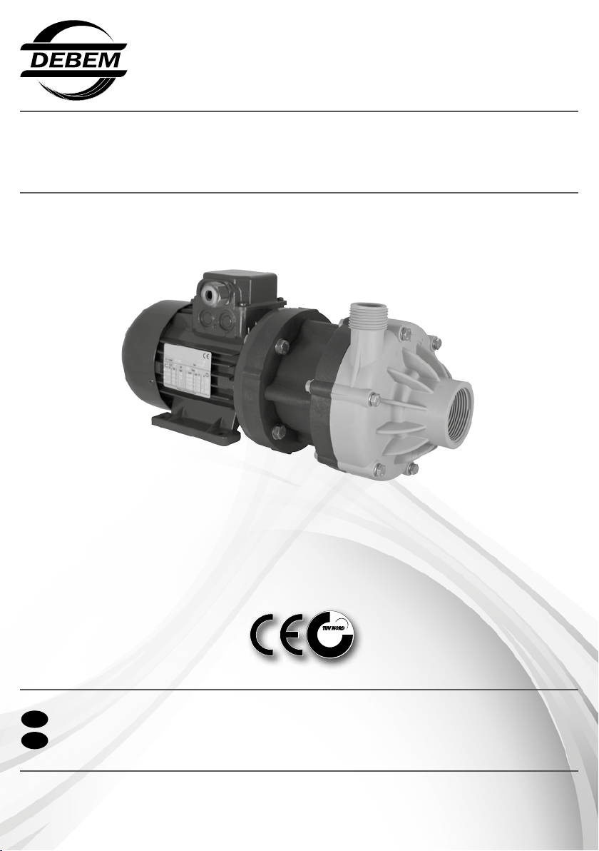
INDUSTRIAL PUMPS - BOMBAS PARA A INDÚSTRIA
petrochemical, food, mechanical, environmental, printing, chemical, painting, galvanic, textile and ceramic, industry
DM
P
INSTRUÇÕES DE USO E MANUTENÇÃO
GB
INSTRUCTIONS FOR USE AND MAINTENANCE
DM 03/2014
TÜV NORD Italia
I
S
O
S.r.l.
1
0
0
9
www.debem.it
Page 2

Debem SRL
2014
Os direitos de tradução, reprodução e adaptação
total ou parcial com qualquer meio são reservados
e, portanto, estes procedimentos estão proibidas,
em todos os países.
Debem SRL
2014
All rights of total or partial translation, reproduction
and adaptation by any means are reserved
in all countries.
www.debem.it
2
Page 3

SUMÁRIO
P
CARTA NO ATO DA ENTREGA 4
INTRODUÇÃO AO MANUAL 4
IDENTIFICAÇÃO DA BOMBA 6
CÓDIGO DE IDENTIFICAÇÃO 6
DESCRIÇÃO DA BOMBA 7
CARACTERÍSTICAS TÉCNICAS 8
MODALIDADES DE GARANTIA 12
PRESCRIÇÕES DE SEGURANÇA 13
DECADÊNCIA DA RESPONSABILIDADE POR REAÇÕES QUÍMICAS 15
PRECAUÇÕES DE INSTALAÇÃO E USO 16
TRANSPORTE E POSICIONAMENTO 17
LIGAÇÃO DO CIRCUITO PRODUTO 20
LIGAÇÃO ELÉTRICA DO MOTOR E CONTROLE DA ROTAÇÃO 21
COLOCAÇÃO EM SERVIÇO 25
PERIODICIDADE DA MANUTENÇÃO ORDINÁRIA 26
MANUTENÇÃO DO CIRCUITO PRODUTO 27
ABERTURA DA BOMBA E LIMPEZA INTERNA 28
DESMONTAGEM 29
ACOPLAMENTO 30
BUSCA AVARIAS 31
COLOCAÇÃO FORA DE SERVIÇO 33
ELIMINAÇÃO E DEMOLIÇÃO 33
PEÇAS DE REPOSIÇÃO 34
GB
INDEX
FOREWORD 4
INTRODUCTION 4
PUMP IDENTIFICATION 6
IDENTIFICATION CODES 6
PUMP DESCRIPTION 7
TECHNICAL FEATURES 8
WARRANTY 12
SAFETY RULES 13
CHEMICAL REACTION DISCLAIMER 15
INSTALLATION/OPERATION PRECAUTIONS 16
TRANSPORTING AND POSITIONING 17
CONNECTING THE PRODUCT CIRCUIT 20
ELECTRICAL MOTOR CONNESCTION AND ROTATION CHECK 21
START UP 25
STANDARD MAINTENANCE TIME-SCHEDULE 26
MAINTENANCE FOR THE PRODUCT CIRCUIT 27
PUMP OPENING AND INTERNAL CLEANING 28
DISASSEMBLY 29
ASSEMBLY 30
TROUBLESHOOTING 31
DECOMMISSIONING 33
DEMOLITION AND DISPOSAL 34
SPARE PARTS 34
PAG.
PAGE
3
info@debem.it
Page 4

CARTA NO ATO DA ENTREGA
P
As bombas de arrasto magnético DM foram realizadas de
acordo com a Diretiva 2006/42/CE.
Portanto, não apresentam perigo para o operador, se utilizadas em conformidade com as instruções deste manual.
O manual deve ser guardado em bom estado e/ou junto à
máquina, para futuras consultas por parte do encarregado
pela manutenção.
O Fabricante não assume quaisquer responsabilidades em
caso de modicação, alteração, aplicações incorretas ou, em
todo caso, operações realizadas em desacordo com quanto
escrito neste manual, que possam determinar danos à segurança, à saúde das pessoas ou animais ou bens materiais
próximos da bomba.
É desejo do Fabricante que os clientes possam ser beneciados
completamente pelo desempenho das bombas centrífugas de
FOREWORD
GB
The DM magnetic centrifugal pumps pumps have been manufactured in accordance with the 2006/42/EC directives.
Therefore, when used according to the instructions contained
in this manual, the Boxer pumps will not pose any risk to the
operator.
This manual must be kept in good condition and/or be kept
with the machine as a reference for maintenance purposes.
The manufacturer declines any liability concerning any changes,
modications, incorrect use or operation not complying with the
contents of this manual and that may constitute a health and
safety hazard to people, animals or property nearby the pump.
The Manufacturer trusts you will take full advantage of the
performance offered by DM horizontal, centrifugal pumps.
INTRODUÇÃO AO MANUAL
P
Este manual é parte integrante da bomba; é um DISPOSITIVO
DE SEGURANÇA e contém as informações importantes para
que o Comprador e seu pessoal instalem, utilizem e mantenham
a bomba em constante estado de eciência e segurança, ao
longo de toda sua vida útil.
No começo de cada Capítulo e de cada seção, foi criada uma
linha de estado que, mediante símbolos, indica o pessoal
habilitado à operação, as proteções individuais obrigatórias e/
ou o estado de alimentação da bomba.
O risco residual durante a operação é evidenciado com sím-
bolos especícos, integrados ao texto.
Gracamente, no manual, serão utilizados símbolos para
evidenciar e diferenciar informações especícas
arrasto magnético DM.
Todos os valores técnicos referem-se às bombas DM padrão
(ver “CARACTERÍSTICAS TÉCNICAS”), mas lembramos
que, em virtude da nossa busca constante de inovação e
qualidades tecnológicas, tais características poderiam sofrer
variação sem aviso prévio.
Os desenhos e qualquer outro documento entregue junto com
o dispositivo pertencem ao Fabricante, e portanto todos os
direitos derivantes são reservados. Assim sendo, o Fabricante PROÍBE a disponibilização a terceiros deste material, sem
que haja a sua aprovação prévia, por escrito.
PORTANTO, É TERMINANTEMENTE PROIBIDA A REPRODUÇÃO, INCLUSIVE PARCIAL, DESTE MANUAL, DO TEXTO E DAS ILUSTRAÇÕES.
All technical parameters refer to the standard DM models
(please see “TECHNICAL FEATURES”). However, the constant
search for innovation and technological quality means that the
characteristics detailed herein may change without prior notice.
All of the drawings and any other documentation supplied with
the pump are the property of the Manufacturer, who reserves
all rights and FORBIDS distribution to third parties without his
authorization in writing.
THEREFORE REPRODUCTION, EVEN PARTIAL, OF THIS
MANUAL, TEXT OR DRAWINGS IS STRICTLY FORBIDDEN.
ou sugestões prestadas em termos de segurança e de correta
condução da bomba.
PARA QUALQUER ESCLARECIMENTO RELATIVO AO
CONTEÚDO DESTE MANUAL, CONTATAR O SERVIÇO DE
ASSISTÊNCIA DO FABRICANTE.
GB
INTRODUCTION
This manual is an integral part of the pump, and represents a
SAFETY DEVICE. It contains important information that will
assist the purchaser and his personnel in installing and using
the pump and ensuring that the pump is kept in safe and good
working order throughout its working life.
At the beginning of each chapter and section there is a status
bar: its symbols state the personnel qualied for the operation/
s in question, the compulsory individual protective devices to
wear and/or the power state of the pump. Any other hazard that
may occur during operations is highlighted by special symbols
embedded in the text.
Special identication symbols are used to highlight and differentiate particular information or suggestions concerning safety
www.debem.it
and the pump’s correct use.
FOR ANY FURTHER INFORMATION REGARDING THE
CONTENTS OF THIS MANUAL, PLEASE CONTACT THE
MANUFACTURER’S ASSISTANCE DEPARTMENT.
4
Page 5
I
GB
ATTENZIONE:
il personale addetto all’installazione, all’ispezio-
ne e alla manutenzione della pompa deve avere
adeguata preparazione tecnica unita a cognizioni
idonee al campo di applicazione (compatibilità ade-
guate in materia e rischi connessi ad eventuali reazio-
ni chimiche del prodotto da pompare).
INSTALLATORE/MANUTENTORE ELETTRICO:
questa qualifica presuppone una piena conoscenza e
comprensione delle informazioni contenute nel manuale
d’uso del costruttore, competenza tecnica specifica per
effettuare gli interventi di natura elettrica di: allacciamento,
manutenzione ordinaria e/o riparazione.
INTERVENTI STRAORDINARI: identifica gli interventi
riservati a tecnici del servizio di assistenza eseguiti
solo presso le officine del Costruttore.
WARNING
personnel responsible for pump installation,
inspection and maintenance shall possess a suitable
technical background along with knowledge of the
field of application (compatibility of materials and risks
associated with possible chemical reactions of the
product being pumped).
ELECTRICAL/FITTER AND MAINTENANCE
ENGINEER
!
!
P
ATENÇÃO: indica ao pessoal interessado que a
!
operação descrita apresenta risco de exposições
a perigos residuais com a possibilidade de danos
à saúde ou lesões se não for realizada no respeito dos
procedimentos e prescrições descritas em conformidade
com as normas de segurança.
AVISO: indica ao pessoal interessado que a operação
descrita pode causar danos à máquina e/ou a seus
componentes e consequentes riscos para o operador
e/ou o ambiente, se não for realizada no respeito das normas
de segurança.
OBS.: fornece informações relativas à operação em
andamento, cujo conteúdo é de consideração ou im-
portância relevante.
SÍMBOLOS DE OBRIGAÇÃO E PROTEÇÕES INDIVIDUAIS: Indica a obrigação e o uso de proteções indivi-
duais adequadas e o estado energético em consequência ao perigo que se pode vericar durante a operação.
OPERADOR: esta qualicação pressupõem pleno
conhecimento e total compreensão das informações
contidas no manual de uso do fabricante, além de
competências especícas do tipo de setor prossional.
INSTALADOR MECÂNICO E ENCARREGADO
PELA MANUTENÇÃO MECÂNICA: esta qualicação
pressupõe o pleno conhecimento e total compreensão
das informações contidas no manual de uso do fabricante, com-
petência especíca para realizar as operações de instalação
e manutenção ordinária, além de competências especícas
do setor.
!
ATENÇÃO: o pessoal encarregado da instalação, da
inspeção e da manutenção da bomba deve possuir
adequada preparação técnica, aliada a conhecimentos pertinentes ao campo de aplicação (compatibilidades adequadas
em matéria e riscos ligados a eventuais reações químicas do
produto a ser bombeado).
INSTALADOR ELETRICISTA E ENCARREGADO
PELA MANUTENÇÃO ELÉTRICA: esta qualicação
pressupõem pleno conhecimento e total compreensão
das informações contidas no manual de uso do fabricante,
bem como competência técnica especíca para realizar as
operações de natureza elétrica de: ligação, manutenção ordinária e/ou conserto.
OPERAÇÕES EXTRAORDINÁRIAS: Identica as
operações cuja execução é restrita aos técnicos
do serviço de assistência, somente nas ocinas do
Fabricante.
GB
WARNING: this sign warns the relevant personnel
!
that the operation in question involves the risk of
exposure to various types of health hazards or
injuries, unless it is carried out according to current safety
norms.
WARNING: This sign warns the relevant personnel that
the operation in question might damage the machinery
and/or its components, with consequent hazard to the
operator and/or the environment, unless it is carried out in
accordance with current safety norms.
NOTE: This note supplies relevant and important infor-
mation on the current operation.
SYMBOLS FOR COMPULSORY AND PERSONAL SAFETY: indicate compulsory, adequate personal protection
and the hazard/s that might occur during operation
consequent to the power status indicated.
OPERATOR: This qualication implies a full knowled-
ge and understanding of the information contained in
this manual, besides a specic competence in the
eld of employment.
INSTALLER AND MECHANICAL MAINTENANCE
OPERATOR: This qualication implies a full knowledge
and understanding of the information contained in the manu-
facturer’s use manual, a specic competence to carry our
standard installation and maintenance operations beside a
specic competence in the eld of employment.
WARNING Installation, inspection and maintenance
!
personnel must have adequate technical training as
well as an adequate knowledge of their eld of operation (correct compatibility of materials and hazards related to possible chemical REACTIONS OF THE PRODUCT
TO BE PUMPED.
ELECTRICAL INSTALLER-MAINTENANCE OPERATOR: This qualication implies a comprehensive
knowledge and understanding of the information
contained in the manufacturer’s user manual, technical com-
petence specic to electrical operations: connection, standard
maintenance and/or repairs.
EXTRAORDINARY OPERATIONS: identify work restricted to service technicians that can only be carried
out in the manufacturer’s workshop.
5
info@debem.it
Page 6
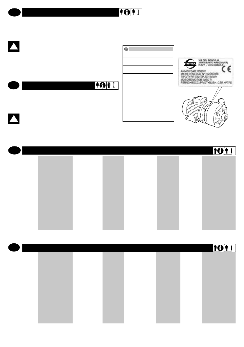
IDENTIFICAÇÃO DA BOMBA
DM
senza motore - whitout motor
DICHIARAZIONE DI CONFORMITA’
DECLARATION DE CONFORMITE - DECLARACION DE CONFORMIDAD
ERKLÄRUNG BEZÜGLICH EINHALTUNG DER VORSCHRIFTEN - DECLARATION OF CONFORMITY
TIPO/SERIE
TYPE / SERIE- TIPO / SERIE - TYP / SERIE - TYPE / SERIES
FABBRICATO DA:
FABRIQUE PAR - FABRICADA POR - HERGESTELLT VON - MANUFACTURED BY
MODELLO
MODELE - MODELO - MODELL - MODEL
CODICE
CODE - CODE - KODE - CODICE
MATRICOLA
SERIAL NUMBER - MATRICULE - MATRIKELNUMMER - MATRICULA
DEBEM SRL - Via del bosco 41 - 21052 Busto Arsizio (VA) - ITALIA
Questo prodotto è conforme alle seguenti direttive CE/EX e relativi standard armonizzati:
This product complies with the following European Community Directives CE/EX and relating harmonized standards:
Ce produit est conforme aux directives de la Communautè europèenne suivantes CE/EX et les normes correspondantes harmonisées:
Este producto cumple con las siguientes Directrices de la Comunidad Europea CE/EX y relativas normas armonizadas:
Dieses Produkt erfüllt die folgenden Vorschriften der Europäischen Gemeinschaft CE/EXund entsprechende harmonisierte Normen:
2006/42/CE Direttiva Macchine / Machinery Directive / Maschinenrichtlinie / Directive Machines / Directiva Máquinas
CE EMC 89/336/CEE e alla legislazione nazionale che le traspone - CE LVD 73/23/CEE e alla legislazione nazionale che le traspone
UNI EN ISO 12100-1: 2009 – Sicurezza del macchinario. Concetti fondamentali, principi generali di progettazione. Parte 1: terminologia di base, metodologia.
UNI EN ISO 12100-1: 2009 – Safety of the machinery. Fundamental notions, design general principles. Part 1: Basic terminology, methods.
UNI EN ISO 12100-1: 2009 – Sécurité des machines. Concepts fondamentaux, principes généraux de conception. Partie 1 : terminologie de base, méthodologie.
UNI EN ISO 12100-1: 2009 – Sicherheit von Maschinen.. Grundbegriffe, allgemeine Gestaltungsleitsätze. Teil 1: Grundsätzliche Terminologie, Methodologie.
UNI EN ISO 12100-1: 2009 – Seguridad de la maquinaria. Conceptos fundamentales, principios generales de diseño. Parte 1: terminología de base, metodología.
UNI EN ISO 12100-2: 2009 – Sicurezza del macchinario. Concetti fondamentali, principi generali di progettazione. Parte 2: principi tecnici.
UNI EN ISO 12100-2: 2009 – Safety of the machinery. Fundamental notions, design general principles. Part 2: Technical principles.
UNI EN ISO 12100-2: 2009 – Sécurité des machines. Concepts fondamentaux, principes généraux de conception. Partie 2 : principes techniques.
UNI EN ISO 12100-2: 2009 – Sicherheit von Maschinen. Grundbegriffe, allgemeine Gestaltungsleitsätze. Teil 2: Technische Leitsätze.
UNI EN ISO 12100-2: 2009 – Seguridad de la maquinaria. Conceptos fundamentales, principios generales de diseño. Parte 2: principios técnicos.
UNI EN ISO 3746: 2009 – Acustica. Determinazione dei livelli di potenza sonora delle sorgenti di rumore mediante misurazione della pressione sonora. Metodo di controllo
con una supercie avvolgente su un piano riettente.
UNI EN ISO 3746: 2009 – Sound. Determination of sound power levels for noise sources by measuring the sound pressure. Monitoring method with an enveloping surface
on a reecting plate.
inserire quitipo/serie
inserire quimodello
inserire quicodice
inserire quimatricola
P
Cada bomba tem uma matrícula de identicação que traz as
especicações e os materiais de composição. Para qualquer
comunicação com o fabricante, o revendedor ou os centros de
assistência autorizados, comunicas os dados indicados.
ATENÇÃO: proibido retirar e/ou modicar a matrí-
!
cula de identicação da bomba e/ou os dados nela
registrados.
O código de identicação que aparece em correspondência de
“TIPO” da matrícula, especica a composição e os materiais
de fabricação da bomba, com o objetivo de determinar a idoneidade com o produto que será bombeado.
GB
PUMP IDENTIFICATION
Each pump is tted with an identication plate detailing its
specication and materials. This data must always be reported in
all communications to the manufacturer, dealer or service
centres.
WARNING: It is forbidden to remove and/or modify
!
the identication plate and/or the data therein.
The identication code * listed aside the TYPE heading, details
the pump composition and manufacturing materials in order
to determine its suitability and compatibility with the product
to be pumped.
P
CÓDIGO DE IDENTIFICAÇÃO
DM10
MOD. DA
BOMBA
DM06
DM10
DM15
DM30
P-
CORPO DA
BOMBA
P - Polipropileno
FC - PVDF +Cf
S
ANEL
SUPORTE DE
IMPULSO
S - Standard
(cerâmica +
PTFE grafite)
D
O-RING
D - EPDM
V - Viton®
HÉLICE
DM06
DM10
DM15
DM30
1
1=Ø81
2=Ø70
3=Ø65
1=Ø98
2=Ø85
3=Ø70
1=Ø123
2=Ø 108
3=Ø 90
1=Ø 134
2=Ø 122
3=Ø 110
N
ENGATES
N - NPT
B - BSP
E
FLANGE
MOTOR
E - MEC
U - NEMA
071
CAIXA MOTOR
DM06
063
071
DM10
071
080
DM15
090
DM30
090
100
112
* Dotazione di serie motore in eurotensione asincrono trifase (2 poli) 50/60 Hz
GB
IDENTIFICATION CODE
DM10
PUMP MODEL
DM06
DM10
DM15
DM30
* Standard motor is the three-phase induction type with European voltage (2-pole) 50Hz
www.debem.it
P-
PUMP BODY
P - Polypropylene
FC - PVDF +Cf
S
THRUST
WASHER
S - Standard
(ceramic +
PTFE graphite)
D
O-RING
D - EPDM
V - Viton®
6
IMPELLER
DM06
DM10
DM15
DM30
1
1=Ø81
2=Ø70
3=Ø65
1=Ø98
2=Ø85
3=Ø70
1=Ø123
2=Ø 108
3=Ø 90
1=Ø 134
2=Ø 122
3=Ø 110
N
CONNECTION
N - NPT
B - BSP
E
MOTOR
FLANGE
E - MEC
U - NEMA
071
MOTOR CASING
DM06
063
071
DM10
071
080
DM15
090
DM30
090
100
112
Page 7
DESCRIÇÃO DA BOMBA
P
Uso previsto
As bombas de arrasto magnético DM foram projetadas e
construídas para o bombeamento sob nível de líquidos com
viscosidade aparente de 1 a 150 cps, de materiais compatíveis quimicamente com os componentes de fabricação da
bomba.
O funcionamento da bomba é permitido com temperaturas de
exercício do uido de -10°C até um máximo de 65°C, para
bombas em PP, e de -10 a 95°C para bombas em PVDF;
em função do tipo de material de composição da bomba (ver
CARACTERÍSTICAS TÉCNICAS, pág. 9)
As bombas centrífugas DM foram projetadas prevendo um
funcionamento até 3500 rotações/minuto, no máximo:
GB
PUMP DESCRIPTION
Recommended use
The DM centrifugal pumps made from resin have been designed
and manufactured to pump below head liquids having an apparent viscosity between 1 and 150 cps, and that are chemically
compatible with the components of the pump.
Fluid service temperatures must range from -10°C to a maximum of 65°C for PP pumps and from -10°C to 95°C for PVDF
pumps; according to the type of material used to build the pump
(pls refer to TECHNICAL CHARACTERISTICS pg. 9).
DM centrifugal pumps are designed for a max working speed
of 3500 revs/min.
P
Princípio de funcionamento
As bombas centrífugas de arrasto magnético DM devem ser
instaladas sob o nível do uido, com oportunas precauções
para evitar a formação de redemoinhos e a consequente aspiração de bolhas de ar. A bomba deve ser feita funcionar
somente e exclusivamente quando estiver SUBMERGIDA.
Um par de magnetos comanda o funcionamento da bomba;
o magneto externo, posicionado no eixo motor, transmite o
movimento ao magneto interno, integrado à hélice, herme-
ticamente isolada. A hélice da bomba não está sicamente
conectada ao eixo motor, portanto são eliminadas as juntas
de vedação e consequentemente os vazamentos do líquido
bombeado por causa do desgaste. O grupo de bombeamento
MOTOR ASSÍNCRONO TRIFÁSICO 2 PÓLOS
- Eurotensão;
- Serviço S1 (serviço contínuo);
- Isolamento em classe F;
- Grau de proteção IP 55
ATENÇÃO: caso o campo de variação da temperatura ambiente e das temperaturas de processo
!
do uido estiverem próximas dos valores máxi-
mos previstos pela bomba, em função dos materiais de
composição (ver CARACTERÍSTICAS TÉCNICAS pág.
10) é necessário instalar no sistema um dispositivo de
proteção que impeça o funcionamento e/ou o alcance da
temperatura de limite.
THREE-PHASE/2 POLES ASYNCHRONOUS MOTOR
- Euro tension;
- S1 status (continuous service)
- Class F insulation;
- IP 55 protection rating.
WARNING: Whenever the variation range of envi-
!
ronmental temperature and of the uid process
temperature approaches the maximum pump temperatures according to the pump’s construction materials
(pls refer to TECHNICAL CHARACTERISTICS, pg 10), it is
necessary to safeguard the plant installing a protection
device stopping the pump and/or preventing it from reaching the threshold temperature.
é fabricado com um baixo número de componentes, tornando
extremamente fácil a manutenção. Os materiais utilizados de
série são o polipropileno (pp) e o poliuoruro de vinilideno
(pvdf).
As bombas não podem funcionar a seco. Líquidos sujos podem reduzir sua vida útil.
ATENÇÃO: qualquer outro uso da bomba centrí-
!
fuga de arrasto magnético DM distinto de quanto
especicado antes, é considerado impróprio e
portanto proibido pela empresa Debem.
GB
Working principles
DM magnetic drive centrifugal pumps must be installed below
head with appropriate procedures to avoid vortex formation
and consequent air bubble suction. The pump must work
ONLY when FLOODED.
A couple of magnets leads the operation of the pump; the outer magnet placed on the drive shaft transmits the motion to
the inner magnet integrated with the impeller that is hermeti-
cally insulated. The pump impeller is not physically xed to
the drive shaft, seals are therefore eliminated and this consequently avoids leakages of the liquid drawn by the pump
which are usually due to its wear and tear. The pump head is
manufactured with few components, thus the maintenance of
which becomes extremely easy. The materials used as stan-
dard are polypropylene (pp) and polyvinylidene uoride (pvdf).
The pumps can’t run dry. Dirty liquids can reduce the pump life
WARNING: use of DM horizontal, centrifugal pum-
!
ps or anything other than that previously descri-
bed is to be considered improper use and is forbidden by Debem.
7
info@debem.it
Page 8
P
Usos impróprios
Especialmente, É PROIBIDO o uso da bomba DM para:
- o bombeamento de gasolina e/ou líquidos inamáveis;
- o bombeamento de líquidos alimentares;
- o uso com sentido de rotação contrário ao estabelecido;
- o uso autocaptante;
- o uso com aspiração em presença de redemoinhos, turbu-
lências ou bolhas de ar;
- o uso em vazio;
- o uso com líquidos a serem bombeados quimicamente incompatíveis com os materiais de fabricação; - o uso com pro-
dutos em suspensão cujo peso especíco for superior ao do
líquido (por exemplo, água com areia);
- com temperaturas e características do produto em desacordo com as características da bomba;
- o uso com águas especialmente duras e/ou muito ricas em
dejetos;
GB
Improper use
It is SPECIFICALLY forbidden to use DM pumps:
- for pumping petrol and/or ammable liquids;
- for pumping food liquids;
- with an opposite rotation to the one specied;
- in self-priming working conditions;
- for suction in the presence of vortexes, turbulence or air
bubbles;
- for vacuum service;
- with liquids that are chemically incompatible with the manufacturing materials;- with products in suspension that have a
higher specic weight than the liquid (e.g. water and sand);
- with product temperatures and characteristics of the pump;
- with water that is particularly hard and/ or full of deposits.
WARNING: due to the wide variety of products
!
and chemical compositions, the operator is considered to be the best evaluator of reactions and
ATENÇÃO: face à inúmera variedade de produtos
e composições químicas, o utilizador é considera-
!
do o maior conhecedor das reações e compatibilidade com os materiais de fabricação da bomba. Portanto,
antes do uso, realizar com cuidado todos os controles e
testes necessários para evitar situações perigosas, mesmo se improváveis, que não podem ser notas e imputá-
veis ao fabricante.
ATENÇÃO: qualquer uso da bomba para além das
!
instruções indicadas no manual de uso e manu-
tenção implica a decadência dos requisitos de
segurança.
Foram analisados os riscos ligados à utilização da bomba nas precisas condições prescritas pelo manual de uso
e manutenção: a análise dos riscos ligados à interface
com outros componentes do sistema é por conta do instalador.
compatibility with the pump’s construction materials.
Therefore, before use, carry out all necessary checks and
tests to avoid any possible hazardous situation, that cannot be predicted or for which the manufacturer cannot be
held liable.
WARNING: use of the pump that does not com-
!
ply with the instructions indicated in the use and
maintenance manual will cancel compliance to the
requirements for safety.
The risks associated with the use of the pump under the
exact conditions set forth in the use and maintenance
manual have been analysed, whilst the analysis of the
risks associated with the interface with other system
components must be carried out by the installer.
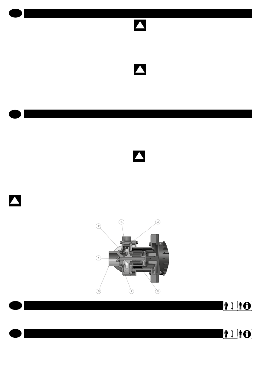
componentes materiais
1
Eixo
Suporte impulso
2
hélice
3
Casquilho PTFE + 30% Grate
4
O-ring VITON/EPDM
5
Hélice PP/PVDF+CF
6
Corpo bomba PP/PVDF+CF
Suporte impulso
7
cabeçote
CARATTERISTICHE TECNICHE
P
Os dados referidos ao desempenho referem-se às execuções padrão. Os valores de “Caudal NOMINAL” e “Prevalência MÁXIMA” referem-se ao bombeamento de água a 18 °C, com aspiração e saída livres.
TECHNICAL SPECIFICATIONS
GB
The data related to performance refer to standard procedures. The NOMINAL ow and the MAX head values refer to pumping
of water at 18°C with free-ow suction and delivery.
www.debem.it
Cerâmica alumina
99,7%
PTFE + 30% Grate
Cerâmica alumina
99,7%
8
components material
1
Shaft
Thrust bearing
2
washer
3
Bearing
4
O-ring VITON/EPDM
5
Impeller PP/PVDF+CF
6
Pump Casing PP/PVDF+CF
Head thrust
7
bearing washer
Alumina
Ceramics 99,7%
PTFE +
30% Graphite
PTFE +
30% Graphite
Alumina
Ceramics 99,7%
Page 9
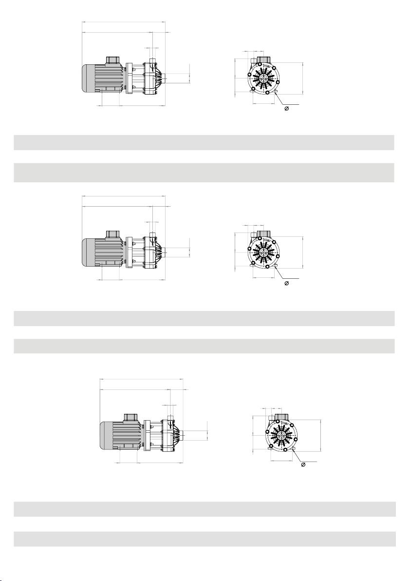
A
mod.
A
DM06
motor
motor
potência
power
A
B
H
C
E
G
A B C E F G H L M N O P
DM06 IEC 63 0,25 Kw 383 325 58 3/4” M
IEC 71 0,37 Kw 404 346 58 3/4” M
DM06
DM06
NEMA
56C
0,5 Hp 436 377 58 3/4” M
DM10
B
H
mod.
motore
motor
potência
power
A B C E F G H L M N O P
DM10 IEC 71 0,55 Kw 417 349 68 1” M
DM10
DM10
IEC 80 0,75 Kw 459 391 68 1” M
NEMA 56C 0,75 Hp 448 380 68 1” M
DM10 NEMA 143TC 1,00 Hp 482 414 68 1” M
C
E
G
M L
F
N O
P
*
1” F*211 80 27 46 63 91 100 6,7 7
*
1” F*217 90 27 46 71 91 112 7,5 7,8
*
1” F*228 90 27 46 89 91 112 - -
M L
F
N O
P
*
1”1/2 F*229 90 25 47 71 91 112 8,6 9
*
1”1/2 F*346 100 25 47 80 91 125 10,6 11
*
1”1/2 F*240 90 25 47 89 91 112 - -
*
1”1/2 F*245 90 25 47 89 91 112 - -
4 fori/hole
7
4 fori/hole
7, 10, 7, 7
Kg
PPKgPVDF
KgPPKg
PVDF
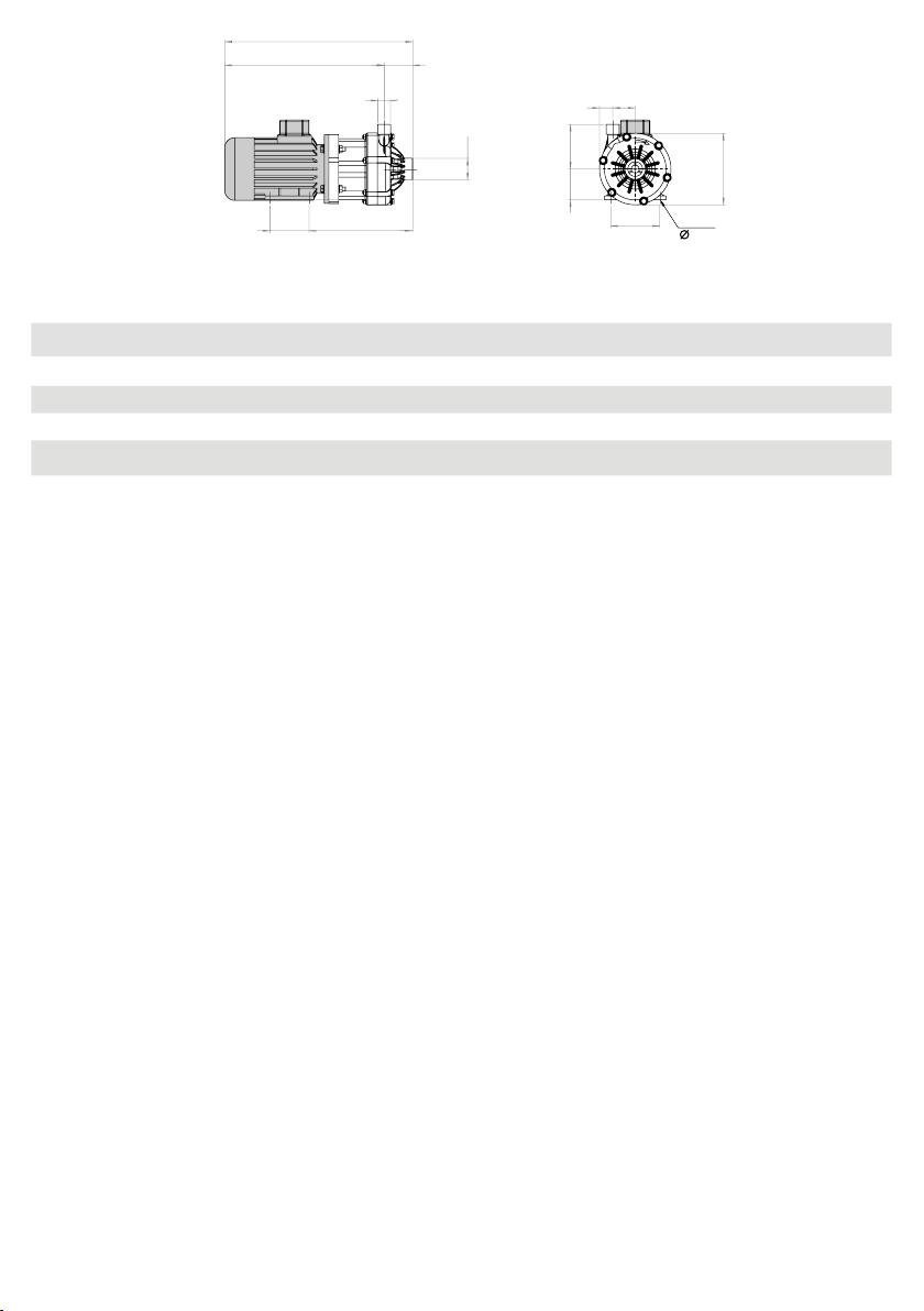
DM15
B
H
mod.
motore
motor
potência
power
A B C E F G H L M N O P
DM15 IEC 90 1,5 Kw 489 408 81 1”
DM15 IEC 90 2,2 Kw 489 408 81 1”
DM15 NEMA 145 TC 3 Hp 530 449 81 1”
C
E
G
F
1/4 M*1”1/2 F*
1/4 M*1”1/2 F*
1/4 M*1”1/2 F*
9
M L
N O
P
4 fori/hole
10, 8.73
KgPPKg
PVDF
298 125 35 62 90 125 140 - -
298 125 35 62 90 125 140 - -
327 127 34 62 88 125 139 - -
info@debem.it
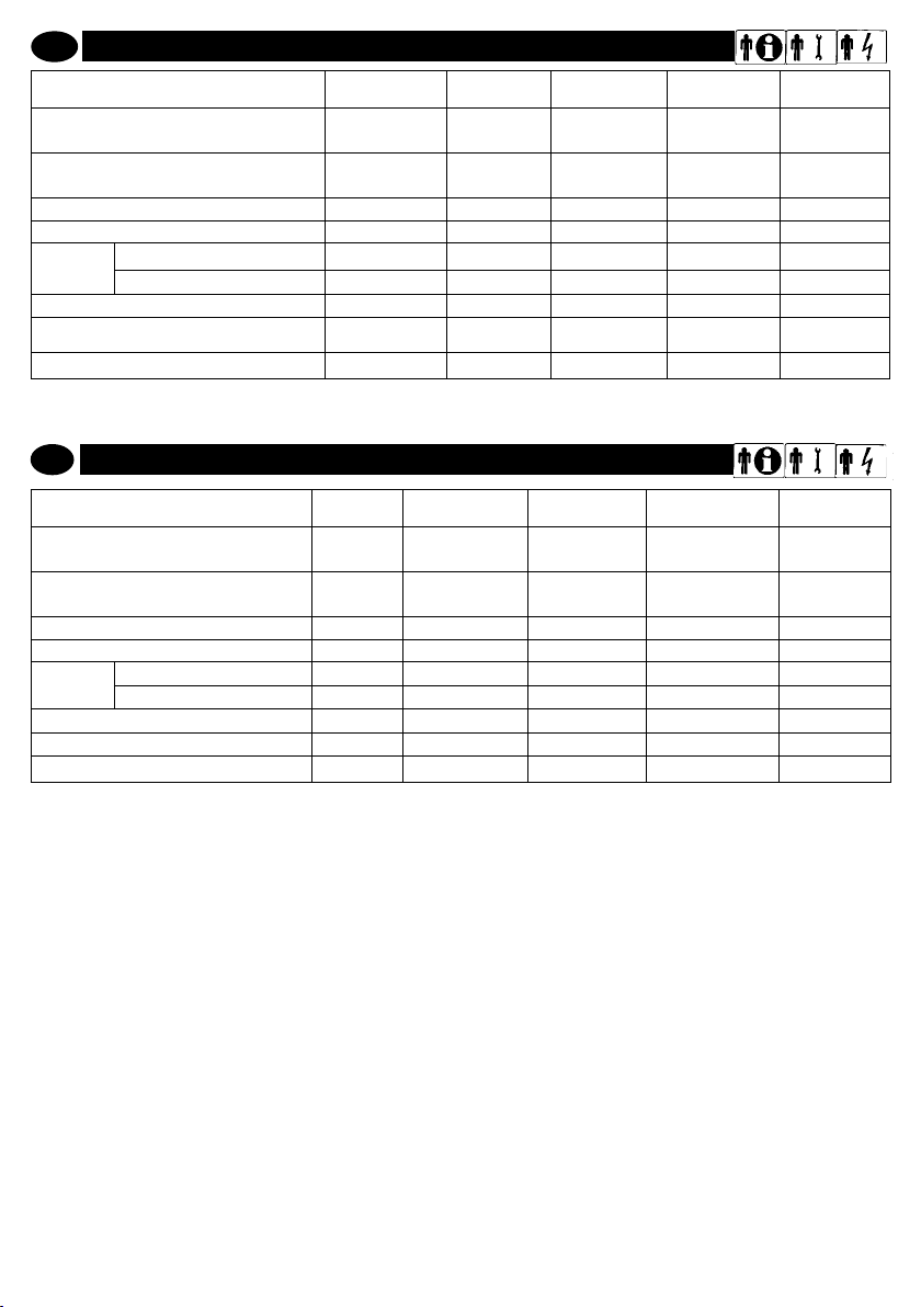
Page 10
A
DM30
B
H
C
E
F
G
M L
N O
P
4 fori/hole
10, 12, 12, 8.73, 10.3
mod.
motor
motor
potência
power
A B C E F G H L M N O P
DM30 IEC 90 2,2 Kw 499 408 91 1”1/2 M
DM30
IEC 100 3 Kw 524 433 91 1”1/2 M
DM30 IEC 112 4 Kw 549 458 91 1”1/2 M
DM30 NEMA 145TC 3 Hp 541 450 91 1”1/2 M
DM30 NEMA 184TC 5 Hp 608 517 91 1”1/2 M
*
2 F*308 125 31 66 90 140 140 - -
*
2 F*315 140 31 66 100 140 160 - -
*
2 F*322 140 31 66 112 140 190 - -
*
2 F*337 127 31 66 88 140 139 - -
*
2 F*328 139 31 66 114 140 190 - -
KgPPKg
PVDF
www.debem.it
10
Page 11
I
GB
ATTENZIONE:
il personale addetto all’installazione, all’ispezio-
ne e alla manutenzione della pompa deve avere
adeguata preparazione tecnica unita a cognizioni
idonee al campo di applicazione (compatibilità ade-
guate in materia e rischi connessi ad eventuali reazio-
ni chimiche del prodotto da pompare).
INSTALLATORE/MANUTENTORE ELETTRICO:
questa qualifica presuppone una piena conoscenza e
comprensione delle informazioni contenute nel manuale
d’uso del costruttore, competenza tecnica specifica per
effettuare gli interventi di natura elettrica di: allacciamento,
manutenzione ordinaria e/o riparazione.
INTERVENTI STRAORDINARI: identifica gli interventi
riservati a tecnici del servizio di assistenza eseguiti
solo presso le officine del Costruttore.
WARNING
personnel responsible for pump installation,
inspection and maintenance shall possess a suitable
technical background along with knowledge of the
field of application (compatibility of materials and risks
associated with possible chemical reactions of the
product being pumped).
ELECTRICAL/FITTER AND MAINTENANCE
ENGINEER
!
!
P
DADOS TÉCNICOS Unidade de
Aspiração
(f = fêmea / m = macho)
Engate saída
(m = macho)
Rotações MÁXIMAS bomba (nominais) rotações/min.
Temp. Máxima uso bomba
Prevalência MAX *
Caudal MAX *
(3000 rot./min. com água a 18°C)
Ruído dB (A)
* Os valores referem-se a bomba com aspiração e saída livres, com água a 18°C
GB
TECHNICAL DATA
Suction Connection
(f = female thread / m = male thread)
Delivery connection (m = male thread)
MAX pump rev. (nominal)
MAX pump temperature
MAX head *
MAX ow rate*
Noise dB (A)
* The values refer to a pump with open suction and delivery with water at 18°C
- PP
- PVDF
- PP
- PVDF
(at 3000 rev/min with water at 18°C)
medida
polegadas
polegadas
C°
C°
m
mc/h
unit
inches
inches
r.p.m. 3500 3500 3500 3500
C°
C°
m 8,5 13,8 19,8 24
mc/h 6,5 13 23,5 36
DM
06
G 1” F
G BSP o NPT
G 3/4” M
BSP o NPT
3500 3500 3500 3500
65 65 65 65
95 95 95 95
8,5 13,8 19,8 24
6,5 13 23,5 36
48 52 58 58
DM
06
G 1” F
G BSP o NPT
G 3/4” M
BSP o NPT
65 65 65 65
95 95 95 95
48 52 58 58
G BSP o NPT
BSP o NPT
DM
10
G 1” 1/2 F
G BSP o NPT
G 1” M
BSP o NPT
DM
10
G 1” 1/2 F
G 1” M
DM
15
G 1” 1/2 F
G BSP o NPT
G 1” 1/4 M
BSP o NPT
DM
15
G 1” 1/2 F
G BSP o NPT
G 1” 1/4 M
BSP o NPT
DM
30
G 2” F
G BSP o NPT
G 1” 1/2 M
BSP o NPT
DM
30
G 2” F
G BSP o NPT
G 1” 1/2 M
BSP o NPT
11
info@debem.it
Page 12

MODALIDADES DE GARANTIA
P
PRESCRIZIONI DI SICUREZZA
As bombas de arrasto magnético DM são produtos cuja qualidade nos é reconhecida, com plena satisfação, por todos os
compradores.
Em caso de eventuais anomalias, deverá ser contatado o SER
VIÇO DE ASSISTÊNCIA DO FABRICANTE, o revendedor ou o
centro de assistência mais próximo, que rapidamente prestará
o auxílio necessário.
Em todas as circunstâncias, indicar os dados a seguir:
A – o endereço completo
B – a identicação da bomba
C- a descrição da anomalia
Todas as bombas DM estão cobertas pela seguinte fórmula de
garantia:
1 – A bomba tem garantia de 12 meses para todas as partes
mecânicas nas quais forem evidenciados defeitos. O período
de garantia será calculado a partir da data de entrega.
2 – Todo e qualquer defeito deverá ser noticado ao Fabricante,
por escrito, no prazo de 8 dias.
3 – A intervenção em garantia será realizada exclusivamente
junto às nossas ocinas, prévio envio da bomba defeituosa.
4 - Em caso de conserto ou substituição de partes da bomba, a
garantia não será estendida.
5 – As partes defeituosas deverão ser enviadas de volta ao Fa
bricante, que reserva-se o direito de efetuar um controle das
mesmas na sua ocina, com o objetivo de detectar o real defeito
ou, ao contrário, identicar as causas externas que podem ter
determinado o dano. Caso as partes não resultem defeituosas,
o Fabricante reserva-se o direito de debitar o custo integral das
peças anteriormente substituídas em garantia.
O Fabricante não arcará com as despesas e os riscos do trans
porte das partes defeituosas e das partes consertadas ou das
fornecidas em substituição, com inclusão dos eventuais impos
WARRANTY
GB
The high quality of DM magnetic drive centrifugal pumps has
been conrmed to us on many occasions by the end users.
However, should any defect appear, please contact the
Manufacturer’s After-Sales Service, your dealer or the nearest
Customer Service Department who will help you as quickly
as possible.
In any case, please provide:
A – Your complete address
B – Pump identication
C – Description of the anomaly.
All the DM pumps are covered by the following warranty:
1. Guarantee on mechanical parts of all DM pumps is for 12
months. The warranty period is calculated from the date of
delivery.
2. Every fault must be notied to the Manufacturer within 8 days.
3. Repairs under warranty will only be carried out in our workshop after receiving the pump.
4. The replacement or repair of parts does not extend the
warranty.
5. Faulty parts must be forwarded to the Manufacturer who
reserves the right to test them in this own workshop in order to
identify the fault or any external reason that may have caused
it. Should the parts be found not faulty, the Manufacturer reserves the right to invoice the total cost of the parts that had
been replaced under this warranty.
The Manufacturer is not liable for costs and risks connected
to transportation of faulty and repaired parts and neither for
those supplied as spare parts, including possible custom duties.
-
-
-
-
www.debem.it
tos alfandegários. O conserto ou a substituição das partes com
defeito constitui plena satisfação das obrigações de garantia. A
garantia NÃO cobrirá algum dano indireto e, especialmente, a
eventual falta de produção. Além disso, estão excluídos da ga
rantia todos os materiais de consumo e desgaste normal (juntas
de vedação). Não estão cobertas pela garantia as partes que
resultarem danicadas por causa de instalação errada, negli
gência ou descuido no uso, manutenção errada e/ou insucien-
te, danos devidos ao transporte e por qualquer circunstância
que não se rera a defeitos de funcionamento ou de fabricação.
Especialmente, a garantia não cobre:
- avarias determinadas por utilização ou instalação não correta
no sistema;
- uso das bombas distinto daquele declarado pelo comprador
no ato do pedido;
- danos derivantes do uso a seco e/ou em presença de bolhas
de ar;
- danos derivantes de abrasões;
- danos derivantes de corpos estranhos nas bombas;
- danos causados pela rotação contrária do motor e da bomba;
- uso das bombas em temperaturas superiores àquelas permi
tidas;
- danos das vedações mecânicas (que estão particularmente
sujeitas a desgaste), salvo evidentes defeitos de construção;
- danos provocados por águas especialmente carregadas de
dejetos
A garantia está excluída em todos os casos de uso impróprio
ou aplicações incorretas e da inobservância das informações
contidas neste manual.
Para dirimir eventuais controvérsias, o Foro competente é
o de Busto Arsízio, Itália.
Repair and replacement of faulty parts entirely fulls the warranty.
This warranty DOES NOT cover any indirect damages, in particular lost production. Moreover, the warranty does not cover
any consumable materials (gaskets).
The warranty does not include parts damaged as a consequence of carelessness, neglect, incorrect installation, lack of
and/or incorrect maintenance, or damages due to transportation or to any other reason or event that is not directly linked to
functioning or manufacturing defects.
The following are specically excluded from the warranty:
- any damage caused by incorrect use or installation of the plant;
- use of the pump other than that declared by the purchaser
at the time of order;
- any damage cause by working in dry conditions and/or presence of air bubbles;
- any damage caused by abrasion;
- any damage caused by foreign matters in the pump;
- any damage caused by reverse rotation of the pump or motor;
- any damage caused by using the pump above the maximum
allowed temperature;
- any damage to mechanical sealing (being subject to wear),
except when a manufacturing defect is obvious;
- any damage caused by water with a high content of deposits.
The warranty is void in all cases of improper or incorrect use
and in case of negligence in following the information herein
contained.
For any controversy, the place of jurisdiction is Busto
Arsizio.
12
-
-
-
Page 13

PRESCRIÇÕES DE SEGURANÇA
P
PRESCRIZIONI DI SICUREZZA
Praticas perigosas, arriscadas ou em desacordo com as prescrições de segurança e com quanto tratado neste manual, podem causar graves lesões, danos materiais ou até mesmo a
morte, não imputáveis ao fabricante.
ATENÇÃO: estas instruções são indispensáveis
!
para a correspondência da bomba aos requisitos
de segurança, portanto devem ser: conhecidas,
disponíveis, compreendidas e aplicadas.
ATENÇÃO: o pessoal encarregado da instalação,
!
da inspeção e da manutenção da bomba deve pos
suir adequada preparação técnica, além de conhe-
cimentos pertinentes ao campo de aplicação (compatibi-
lidades e riscos ligados a eventuais reações químicas do
produto a ser bombeado).
ATENÇÃO: qualquer uso da bomba para além das
!
instruções indicadas no manual de uso e manuten
ção implica a decadência dos requisitos de segu-
rança.
ATENÇÃO: antes de intervir na bomba e/ou antes
de realizar manutenções ou consertos, é necessá-
!
rio:
A – descarregar o produto que está sendo bombeado;
B – providenciar a lavagem interna com uido idôneo (não
inamável);
C – parar o motor da bomba;
D – fechar as válvulas manuais de interceptação produto
(aspiração e saída);
E – cortar e desligar a tensão elétrica de alimentação do
motor da bomba;
F - Usar os equipamentos de proteção individual idôneos
SAFETY INSTRUCTIONS
GB
Dangerous or hazardous practices or practices no complying
with the safety rules and with that recommended herein may
cause injuries, material damage and even death for which the
manufacturer cannot be held responsible.
WARNING: these instructions are indispensable
!
for the pump to comply with safety requirements,
therefore they must be made known, available
and abided to.
WARNING: the personnel in charge of installing,
!
inspecting and servicing the pumps must have
adequate technical knowledge and training in the
eld of application (compatibility and hazards related to
possible chemical reaction of the product/s to pump).
WARNING: use of the pump that does not comply
!
to the instructions indicated in the use and maintenance manual will invalidate all warranty and
safety requirements.
WARNING: before any operation on the pump and/
!
or before any maintenance or repair, proceed as
follows:
A – discharge the product being pumped;
B – proceed with washing the inside with appropriate liquid
(non-ammable);
C – stop the pump motor;
D – close the manual, shut-off valves (suction and delivery
of product);
E - section power to the pump motor;
-
-
para a operação (máscaras para o rosto, luvas, botas de
segurança, aventais etc.):
ATENÇÃO: antes de usar a bomba, certicar-se de
que o uido a ser bombeado seja compatível com
!
os materiais de fabricação: PERIGO DE CORRO
SÕES, VAZAMENTOS DO PRODUTO E/OU EXPLOSÕES
DEVIDAS A REAÇÕES QUÍMICAS.
Para a instalação e o uso respeitar as seguintes precauções gerais:
- controlar que a bomba esteja cheia e o nível esteja, possivelmente, acima desta de pelo menos 0,5 m;
- controlar que no uido tratado não haja ou não possam
chegar partes sólidas;
- que não haja estrangulamentos na aspiração da bomba,
para evitar fenômenos respectivamente de cavitação e es
forço do motor pneumático;
- controlar que as tubulações de conexão sejam idôneas e
resistentes e que a bomba não suporte o seu peso;
- se a bomba tiver que permanecer inativa por longos perío
dos, limpá-la cuidadosamente, fazendo circular um uido
detergente (não inamável) compatível com os materiais
de fabricação da bomba;
- se a bomba tiver que permanecer desligada por longos
períodos, é oportuno deixar circular água limpa por alguns
minutos, para evitar o risco de incrustações;
- proteger sempre a bomba contra possíveis choques, pro
vocados acidentalmente por veículos em movimento ou
materiais diversos contundentes, que poderiam danicá-la
e/ou reagir ao contato;
- proteger o ambiente circunstante dos esguichos derivan
tes de avarias acidentais da bomba;
F – Wear suitable individual protection before any intervention (masks, gloves, closed shoes, aprons, etc.).
WARNING: before using the pump, ensure that the
!
uid to pump is compatible with the manufacturing materials: CORROSION, LEAKAGE AND/OR
EZPLOSION HAZARSDS DUE TO CHEMICAL REACTIONS.
For the installation and use, take the following precautions:
- check that the pump is ooded and the level is at least
0,5 m higher;
- Check that no solid particles are or could oat in the uid;
- Check that there are no constraints to the pump suction,
thus avoiding cavitations and electrical motor strain;
- Check that the connecting pipes are suitable and resistant
and that the pump does not bear their weight;
- If the pump is to be inactive for long periods, clean it thor-
oughly with a detergent uid (non-ammable) compatible
with the pump’s construction materials;
- if the pump must be turned off for a long period of time,
before doing so circulate clean water for some minutes to
avoid incrustations;
- always protect the pump against possible collisions
caused by moving means or by various blunt materials
that may damage it or react with its materials;
- protect the pump’s surrounding environment from
splashes caused by accidental pump failure;
- Supply an adequate guard to collect and direct the treated
product that could leak.
13
info@debem.it
-
-
-
-
-
Page 14

P
PRESCRIZIONI DI SICUREZZA
- prever um adequado anteparo que colete e encaminhe
para uma área segura o produto tratado que poderia vazar.
ATENÇÃO: é PROIBIDO o funcionamento a seco
!
da bomba DM. O funcionamento a seco provoca
a fusão dos elementos em atrito por contato e o
consequente, possível, incêndio.
ATENÇÃO: é PROIBIDO o uso da bomba para ins-
!
talação autocaptante; o duto de aspiração deve
ser instalado sempre sob o nível do uido e longe
de redemoinhos ou turbulências que poderiam causar o
englobamento de ar.
ATENÇÃO: em caso de uso para o bombeamento
!
de uidos agressivos, tóxicos ou perigosos para
a saúde, é necessário instalar na bomba uma ade-
quada proteção para a contenção e a coleta e sinalização
do produto em caso de vazamento: PERIGO DE POLUIÇÃO, CONTAMINAÇÃO, LESÕES E/OU MORTE.
ATENÇÃO: está proibido o uso da bomba com
!
uidos não compatíveis com os materiais dos
componentes ou em ambiente com presença de
uidos não compatíveis.
ATENÇÃO: é proibida a instalação da bomba
sem as válvulas para a interceptação do produto
!
na aspiração e na saída, para isolar o uxo, em
caso de vazamento: PERIGO DE VAZAMENTO DESCONTROLADO DO PRODUTO.
ATENÇÃO: caso o utilizador preveja o risco de exceder
os limites de temperatura previstos por este ma-
nual, é necessário instalar no sistema um dispo-
!
sitivo de proteção que impeça o funcionamento e/
ou o alcance da temperatura de limite (uido e ambiente)
de 95°C para bombas em PVDF e de 65°C para as em PP
(polipropileno).
ATENÇÃO: a bomba deve ser sempre aterrada
!
independente de outro órgão eventualmente co-
nectado.
ATENÇÃO: uidos agressivos, tóxicos ou peri-
!
gosos podem causar graves lesões físicas e/ou à
saúde, portanto é proibido devolver ao produtor
ou a um centro de assistência uma bomba que contenha
produtos deste tipo: Esvaziar e lavar o circuito interno do
produto e providenciar a lavagem e tratamento antes do
envio da bomba.
ATENÇÃO: os modelos de bombas que contêm
!
componentes ou partes de alumínio em contato
com o produto não podem ser utilizadas para o
bombeamento de III-tri-cloro-etanol, o cloro metileno ou
solventes à base de outros hidrocarbonetos halogenados: PERIGO DE EXPLOSÃO POR REAÇÃO QUÍMICA.
ATENÇÃO: vericar que, durante o funcionamen-
!
to, não sejam produzidos ruídos anômalos. Neste
caso, interromper imediatamente o funcionamen-
to da bomba.
GB
WARNING: It is FORBIDDEN to expose an DM pump
!
to dry working conditions; this could cause the
elements exposed to horizontal friction to melt and
possibly cause a re.
WARNING: it is FORBIDDEN to use the pump for
!
self priming installation; the suction conduits must
always be installed below head and away from
vortexes or turbulence that could cause air retention .
WARNING: when pumping aggressive, toxic or
hazardous uids, the pump must be tted with a
!
suitable guard to contain collect and signal the
product in case of leakage: POLLUTION, CONTAMINATION,
INJURY AND/OR DEATH.
WARNING: It is forbidden to use the pump with
uids that are incompatible with the components
!
materials or in an environment with non-compatible
uids.
WARNING: It is forbidden to install the pump with-
out tting the shut-off valves at the suction and
!
delivery of the product that enable the sectioning
required in case of leakage: HAZARD OF UNCONTROLLED
LEAKAGE OF THE PRODUCT.
WARNING: Should the user think that the tempera-
ture limits set forth in this manual may be exceeded
!
during service, a protection device must be in-
www.debem.it
stalled on the system to prevent global temperature (uid
+ ambient) from reaching temperatures higher than 95°C
for PVDF pimps and 65°C for PP (polypropylene) pumps.
WARNING: The pump must always be earthed,
independently from any other equipment con-
!
nected to it.
WARNING: aggressive, toxic or hazardous uids
can cause severe physical injuries and/or damages
!
to health, consequently it is forbidden to return a
pump containing such products to either the manufacturer
or to a service centre. Empty and wash the internal circuit
and treat the pump before delivering it.
WARNING: the models with aluminium parts or
components in contact with the product cannot
!
be used for pumping III-trichloroethylene, chlorine
methylene or any halogenated, hydrocarbon-based solvent: EXPLOSION HAZARD DUE TO CHEMICAL REACTION.
WARNING: Check that there is no abnormal noise
during functioning. In this case, stop the operation
!
of the pump immediately.
WARNING: check that the output uid does not
!
carry air or gas; in this case, stop the pump imme-
diately and resolve the problem before restarting it.
14
Page 15

P
PRESCRIZIONI DI SICUREZZA
ATENÇÃO: controlar que no uido em saída não
!
haja ar ou gases; em caso positivo, interromper
imediatamente o funcionamento da bomba e solucionar o problema antes de recolocá-la em funcionamento.
ATENÇÃO: é proibido o uso das bombas DM para
!
águas especialmente duras e/ou muito ricas de
dejetos que provoquem incrustações anômalas
na vedação mecânica.
AVISO: Para a substituição de partes desgasta-
!
das, utilizar apenas peças de reposição originais.
A não observância das disposições acima pode
gerar perigos para o operador, os técnicos, as pessoas expostas, a bomba e/ou o ambiente, não im-
putáveis ao fabricante.
GB
WARNING: it is prohibited to use DM Pumps with
!
water that is particularly hard and/or has a high
content of deposits as it may cause anomalous
incrustations on the mechanical seal.
WARNING: Only use original spare parts for re-
!
placements.
P
DECADÊNCIA DA RESPONSABILIDADE POR REAÇÕES QUÍMICAS
PRESCRIZIONI DI SICUREZZA
Precauções
ATENÇÃO: Ler todo o manual antes de instalar
!
ou utilizar esta unidade. O desrespeito destas
precauções pode comportar graves acidentes ou
morte.
ATENÇÃO: Perigo campo magnético. Esta bomba
!
contém potentes magnetos. Os magnetos expostos (quando a bomba não estiver acoplada ao
motor) produzem fortes campos magnéticos. Pessoas
com marca-passos, debriladores, dispositivos médicos
eletrônicos, válvulas cardíacas protéticas em metal, pontos metálicos internos (derivantes de cirurgias), disposi-
tivos protéticos em metal ou anemia mediterrânea não
devem manusear ou estar perto dos magnetos contidos
na bomba. Aconselhamos consultar um médico para re-
comendações especícas antes de colocar a bomba em
funcionamento.
CHEMICAL REACTION DISCLAIMER
GB
Warnings
ATTENTION: Fully read the manual before instal-
!
ling or using this unit. Non-compliance with these
precautions may cause serious injury or death.
ATTENTION: Danger of magnetic eld. This pump
!
contains powerful magnets. The exposed magnets
(when the pump is not connected to the motor)
produce strong magnetic elds. People with pacemakers,
defibrillators, electronic medical devices, prosthetic
cardiac valves in metal, internal metal stitches (due to
surgery), prosthetic devices in metal or Thalassemia must
not handle or be in the proximity of magnets contained
inside the pump. We recommend you consult your doctor
for specic advice before operating this pump.
15
The manufacturer is not liable for hazards to the
operator, technicians, people exposed, the pump
and/or the environment caused by non-compliance
with the above.
ATENÇÃO: Perigo de força magnética. Esta bom-
!
ba deve ser montada e desmontada somente
seguindo os procedimentos recomendados. A
atração magnética é bastante poderosa, a ponto de atrair
o motor e as tubulações. Para evitar acidentes, manter
os dedos longe das superfícies de encaixe ente motor e
tubulações. Manter o magneto e a hélice longe de raspas
ou partículas, objetos com bandas magnéticas como
cartões de créditos, ou suportes informáticos como op-
py disk ou discos duros.
ATENÇÃO: superfícies quentes. Esta bomba pode
!
ser utilizadas com uidos cuja temperatura che-
gue até a 104 °C. Isto comporta que as superfícies
externas da bomba possam aquecer e causar queimaduras.
ATTENTION: Danger of magnetic force. This pump
!
should be dismantled and assembled according
to the recommended procedures only. Magnetic
attraction is powerful enough to attract the motor and
tubing together. To avoid injury, keep your ngers far from
the slotted surfaces between the motor and the tubing.
Keep the magnet and the impeller far from chips and
particles, objects with magnetic tape such as credit cards
and electronic media such as oppy disks or hard disks.
ATTENTION: hot surfaces. This pump may be
!
used with liquids up to a temperature of 104. C).
This means the external surfaces of the pump can
become hot and cause burns.
info@debem.it
Page 16

P
PRESCRIZIONI DI SICUREZZA
ATENÇÃO: Partes giratórias. Esta bomba é equi-
!
pada com partes que giram durante o funciona-
mento. Observar as normas de segurança locais
para isolar o motor da rede elétrica durante as operações
de manutenção ou assistência técnica.
ATENÇÃO: Risco químico. Esta bomba é utilizada
!
para a transferência de muitos tipos de substân-
cias químicas potencialmente perigosas. Usar
sempre roupas de proteção óculos de proteção e seguir
os procedimentos de segurança padrão no manuseio de
substâncias corrosivas ou prejudiciais à pessoa. Procedimentos adequados devem ser observados para a drenagem e a descontaminação da bomba antes da desmon-
GB
ATTENTION: Rotating parts. This pump contains
!
parts that rotate during functioning. Adhere to lo-
cal safety standards to disconnect the motor from
the electrical mains during maintenance and servicing
operations.
ATTENTION: Chemical risk. This pump is used
!
to transfer various types of chemical substances
which are potentially dangerous. Always wear
protective clothing, protective goggles and follow standard
safety procedures when handling substances that are corrosive or harmful to one’s health. Appropriate procedures
must be followed for the drainage and decontamination
PRECAUÇÕES DE INSTALAÇÃO/USO
P
PRESCRIZIONI DI SICUREZZA
ATENÇÃO: esta bomba nunca deve ser utilizada
!
sem líquido no recipiente.
Recomendamos o uso de proteções contra a utilização a seco.
Se a bomba tiver casquilhos em PTFE ou CERÂMICA, não
pode ser utilizada a seco sem que isto comporte danos à
própria bomba.
Em todo caso, a bomba pode ser utilizada sem o líquido
no recipiente se for equipada com casquilhos em Carbono.
O prazo durante o qual a bomba pode trabalhar a seco,
porém, varia a depender das condições de utilização.
ATENÇÃO: nunca ligar ou utilizar com válvula de
!
aspiração fechada.
Nunca acionar a bomba com uma válvula de des-
carga fechada.
tagem e inspeção.
Pequenas quantidades de substâncias químicas podem
estar presentes durante a inspeção.
ATENÇÃO: A bomba e seus componentes são pe-
!
sados. A falta de suporte à bomba durante o seu
levantamento e transporte pode comportar sérios
acidentes ou danos à bomba e às suas partes.
ATENÇÃO: Nunca utilizar a bomba abaixo do caudal mínimo ou com a válvula de descarga fecha-
!
da. Isto pode comportar avarias da bomba.
of the pump before its dismantling and inspection. Small
quantities of chemical substances can be present during
inspection.
ATTENTION: The pump and its parts are heavy.
!
Inadequate support of the pump during lifting and
transport may result in serious injury or damage to
the pump and its parts.
ATTENTION: Never use the pump under the mini-
!
mum capacity or with the discharge valve closed.
This may cause the pump to break down.
OBS.: A temperatura máxima depende da aplicação. Aconselhamos consultar uma tabela de resis-
tência química ou o produtor do composto químico
para os limites de compatibilidade e temperatura.
Sólidos: As dimensões máximas de partículas são de
100 mícrons para os descartes e de 1/64’’ (0,4 mm) para
partículas raras. A dureza máxima é de 80 HS. A concentração máxima é de 10% do peso. Bombear elementos
sólidos pode comportar maior desgaste.
Caudal mínimo permitido: Nunca permitir que o caudal vá
abaixo do mínimo indicado na tabela a seguir:
3450 rpm 2900 rpm
0.25 gpm
INSTALLATION/OPERATION PRECAUTIONS
GB
ATTENTION: this pump must never be used without
!
liquid in the container.
You are advised to protect against dry use.
If the pump has PTFE or CERAMIC bushes, it cannot be
used dry without causing damage to the pump.
In any case, the pump can be used without liquid in the
container if the pump has carbon bushes.
The time during which the pump can dry operate does
however vary based on the conditions of use.
ATTENTION: never switch on or use with a closed
!
suction valve.
Never activate with a closed discharge valve.
www.debem.it
NOTE: The maximum temperature depends on the
application. For a correct information about the
compatibility and temperature limits we advise to
look up a chemical resistance chart or contact the manufacturer of the compound.
Solids: The maximum dimensions of the particles are
100 micron for waste and 1/64’’ (.4 mm) for rare particles.
Maximum hardness is 80 HS. Maximum concentration
is 10% of weight. Pumping solid elements can result in
greater wear and tear.
Minimum capacity permitted: Do not let the capacity go
under the minimum reported in the table below:
16
Page 17

P
PRESCRIZIONI DI SICUREZZA
(0.95 lpm)
0.95 lpm
(.25 gpm)
Potência máxima permitida do motor: Nunca ultrapassar
GB
3450 rpm 2900 rpm
0.25 gpm (0.95 lpm)
0.95 lpm (.25 gpm)
Maximum power of motor permitted: Do not exceed the
TRANSPORTE E POSICIONAMENTO
P
Os operadores encarregados das operações de montagem/
desmontagem devem ser informados acerca dos perigos ligados ao uso de utensílios mecânicos, inclusive de dimensões
pequenas.
Ao receber a bomba, vericar que a mesma e a sua embalagem estejam íntegras e não tenham sofrido danos; em seguida, é necessário:
1. Em função do tamanho e do peso, os materiais são fornecidos em embalagem de papelão, sobre palete ou numa caixa
de madeira: ao receber, abrir e retirar a embalagem.
2. Retirar o manual de uso e manutenção e operar como descrito.
3. Suspender a bomba com equipamentos de levantamento
adequados ao peso indicado na placa.
4. Realizar uma vericação do aperto de todos os parafusos
da bomba.
a potência máxima indicada para a bomba
A potência padrão para o DB3/4/5 é de 4 pólos. A potência
máxima do motor é d 4 kW
maximum power indicated for the pump.
The standard power is DB3/4/5. It is 4 poles. Maximum
power of the motor is 4 kW
OBS.: As bombas DM são fornecidas completas de
motor. Em caso de futuras movimentações, caso a
bomba não esteja equipada com motor, antes de proceder com o posicionamento será necessário providenciar
a sua montagem, operando como indicado pelo Capítulo
“MONTAGEM DA VEDAÇÃO DO MOTOR ELÉTRICO”.
ATENÇÃO: o posicionamento e a xação prevista
!
para a bomba é no sentido horizontal, com estacas no teto ou no piso, nos pés de suporte do
motor. As bombas centrífugas horizontais não são auto-
-alimentadas, portanto devem sempre ser instaladas em
proximidade do ponto de retirada, sem formar sifões na
aspiração.
5 Posicionar corretamente a bomba no local de instalação (o
mais próximo possível ao ponto de retirada) e providenciar
a xação da estacas nos pés de suporte do motor, com os
parafusos adequados. Prever um espaço suciente para as
eventuais futuras manutenções.
TRANSPORTING AND POSITIONING
GB
The operators in charge of the assembly / disassembly must
be informed and trained on the dangers relating to the use of
mechanical tools, even small ones .
When receiving the goods, check that the pump packaging is
undamaged; afterwards proceed as follows:
1. According to the equipment size and weight the plant is
either packaged with cardboard, boxes or on pallets. Open
and discard the packaging;
2. Consult the Use and Maintenance Manual and comply with
its
instructions;
3. Lift the pump with appropriate lifting means, suitable to the
weight indicated on the Id plate.
4. Check the correct tightening of all screws.
NOTE: DM pumps are supplied complete with motor.
In case of future handling, if the pump is detached from
the motor, before proceeding with its positioning it must
be assembled as described in the Chapter: “ASSEMBLY OF
ELECTRIC MOTOR SEALING”.
WARNING: the pumps are designed to be positio-
!
ned and xed horizontally from the ceiling using
hangers or on the oor on the feet of the motor.
The horizontal, centrifugal pumps are not self priming,
therefore they must always be installed next to the suction point, and without forming siphons in suction.
5 Correctly position the pump in the installation area (as close
as possible to the suction point) and proceed with bolting the
motor feet appropriately. Ensure that adequate space is left for
future maintenance operations.
17
info@debem.it
Page 18

4 Effettuare una verifica del serraggio di
tutte le viti della pompa.
NOTA
Le pompe MB vengono fornite
complete di motore. Nel caso di future
movimentazioni, se la pompa è in
assenza del motore, prima di procedere
al posizionamento bisognerà provvedere
al suo montaggio operando come
descritto al Capitolo “MONTAGGIO
DELLA TENUTA DEL MOTORE ELET-
6 Posizionare correttamente la pompa sul
luogo di installazione (più vicina possi-
bile al punto di prelievo) e provvedere
allo staffaggio sui piedini del motore con
appositi bulloni. Prevedere uno spazio
sufficiente per le eventuali future manu-
tenzioni.
OK
6 Posizionare correttamente la pompa sul
luogo di installazione (più vicina possi-
bile al punto di prelievo) e provvedere
allo staffaggio sui piedini del motore con
appositi bulloni. Prevedere uno spazio
sufficiente per le eventuali future manu-
tenzioni.
6. Correctly position the pump in the
installation area (as close as
possible to the suction point) and
OK
OK
200 mm
livello min
min levele
6 Posizionare correttamente la pompa sul
luogo di installazione (più vicina possi-
bile al punto di prelievo) e provvedere
allo staffaggio sui piedini del motore con
appositi bulloni. Prevedere uno spazio
sufficiente per le eventuali future manu-
tenzioni.
6. Correctly position the pump in the
installation area (as close as
possible to the suction point) and
proceed with bolting the motor feet
appropriately. Ensure that adequate
space is left for future maintenance
operations.
1
2
3
ISTRUZIONI PER L’USO E LA
MANUTENZIONE
INSTRUCTIONS FOR USE AND
MAINTENANCE
MB
4 Effettuare una verifica del serraggio di
tutte le viti della pompa.
NOTA
Le pompe MB vengono fornite
complete di motore. Nel caso di future
movimentazioni, se la pompa è in
assenza del motore, prima di procedere
al posizionamento bisognerà provvedere
al suo montaggio operando come
descritto al Capitolo “MONTAGGIO
DELLA TENUTA DEL MOTORE ELET-
TRICO”.
4 Check the correct tightening of all
screws.
NOTE:
MB pumps are supplied complete
with motor. In case of future handling,
if the pump is detached from the motor,
before proceeding with its positioning it
must be assembled as described in
the Chapter: “ASSEMBLY OF
ELECTRIC MOTOR SEALING”.
POMPE CENTRIFUGHE ORIZZONTALI
HORIZONTAL CENTRIFUGAL PUMPS
1
4 Effettuare una verifica del serraggio di
tutte le viti della pompa.
NOTA
Le pompe MB vengono fornite
complete di motore. Nel caso di future
movimentazioni, se la pompa è in
assenza del motore, prima di procedere
al posizionamento bisognerà provvedere
al suo montaggio operando come
descritto al Capitolo “MONTAGGIO
DELLA TENUTA DEL MOTORE ELET-
TRICO”.
POMPE CENTRIFUGHE ORIZZONTALI
HORIZONTAL CENTRIFUGAL PUMPS
1
2
ISTRUZIONI PER L’USO E LA
MANUTENZIONE
INSTRUCTIONS FOR USE AND
MAINTENANCE
MB
4 Effettuare una verifica del serraggio di
tutte le viti della pompa.
NOTA
Le pompe MB vengono fornite
complete di motore. Nel caso di future
movimentazioni, se la pompa è in
assenza del motore, prima di procedere
al posizionamento bisognerà provvedere
al suo montaggio operando come
descritto al Capitolo “MONTAGGIO
DELLA TENUTA DEL MOTORE ELET-
TRICO”.
4 Check the correct tightening of all
screws.
NOTE:
MB pumps are supplied complete
with motor. In case of future handling,
if the pump is detached from the motor,
before proceeding with its positioning it
must be assembled as described in
the Chapter: “ASSEMBLY OF
ELECTRIC MOTOR SEALING”.
POMPE CENTRIFUGHE ORIZZONTALI
HORIZONTAL CENTRIFUGAL PUMPS
sinal
de perigo
genérico
General
Danger Sign
proibido
fumar
ISTRUZIONI PER L’USO E LA
MANUTENZIONE
INSTRUCTIONS FOR USE AND
MAINTENANCE
1
MB
OK
Posicionar os seguintes sinais de proibição e perigo próximo do local de instalação da bomba
perigo
material
corrosivo
Danger
Corrosive
Material
obrigação de
vestir macacão
de proteção
perigo
material
inamável
Danger
Flammable
Material
obrigação de
usar óculos
de proteção
obrigação
de proteger
as vias
respiratórias
OK
perigo
material
explosivo
Danger
Explosive
Material
2
livello min
min levele
200 mm
obrigação de
usar luvas
perigo
material
tóxico
Danger Toxic
Material
perigo de borrifos
de material líquido
obrigação de
usar sapato
fechado
3
incandescente
Danger
Incandescent
Liquid Sprinkles
usar máscaras
obrigação de
de proteção
perigo
eletricidade
danger high
voltage
6
proibido
usar chamas
livres
Prohibition
on Open
Flames’ Use
proibido
apagar
incêndios
com água
4
No smoking
www.debem.it
Safety overalls
must be worn
Put the following prohibition and danger signs near the place where the pump is installed
Eye
protection
must be worn
Respiratory
equipment
must be worn
Safety gloves
must be worn
18
Safety boots
must be worn
Face
protection
must be worn
prohibition of
putting out res
with water
Page 19

D- eventuali filtri di aspirazione
devono essere a cestello oppor-
tunamente sovradimensionati
(circa 3 volte la sezione di
aspirazione della pompa, per
evitare perdite di carico);
E- il pescante del tubo di aspira-
zione deve essere alloggiato
al’interno di idoneo stramazzo e
lontano da vortici, turbolenze e
scarichi liberi;
F- prevedere un dispositivo di
livello che determini l’arresto
del motore della pompa al di
sotto del livello minimo.
Il trasporto e posizionamento sono
così terminati.
A
D – any suction filters must be of
the basket-type and
D- eventuali filtri di aspirazione
devono essere a cestello oppor-
tunamente sovradimensionati
(circa 3 volte la sezione di
aspirazione della pompa, per
evitare perdite di carico);
E- il pescante del tubo di aspira-
zione deve essere alloggiato
al’interno di idoneo stramazzo e
lontano da vortici, turbolenze e
scarichi liberi;
F- prevedere un dispositivo di
livello che determini l’arresto
del motore della pompa al di
sotto del livello minimo.
Il trasporto e posizionamento sono
così terminati.
A
B
D – any suction filters must be of
the basket-type and
appropriately over-
dimensioned (approx 3 times
the pump suction diameter, to
avoid loss of pressure);
E – the dip tube of the suction pipe
must be housed inside the weir
and away from vortexes,
turbulence and open drains;
F – fit a level regulator device that
can halt the motor when the
pump is under the minimum
level.
Transportation and positioning are
now completed.
P
PRESCRIZIONI DI SICUREZZA
ATENÇÃO: o funcionamento das bombas DM com
!
elementos pesados em suspensão ou a seco provoca a fusão dos elementos em atrito por contato
e o consequente, possível, incêndio, portanto observar
as normas a seguir:
A – a bomba não é auto-alimentada e deve ser sempre
instalada sob o nível do uido;
B – a extremidade do tubo de aspiração da bomba deve
ter forma tal que evite entupimentos devidos à sucção,
a manchas e substâncias pesadas e deve estar longe de
redemoinhos ou tubos de enchimento do tanque;
C – o tubo de aspiração não deve formar sifões;
GB
WARNING: DM pumps working with heavy elements
!
in suspension or in dry conditions can damage the
sealing as well as causing the fusion of sliding fric-
tion parts that may give rise to re, therefore the following
rules must be complied with:
A – the pump is not self priming and must be positioned
below head:
B – the dip tube of the suction pipe must be bent to avoid
clogging due to reux, grit and heavy matter, and it must
be kept away from vortexes or the tank lling pipes;
D – eventuais ltros de aspiração devem ser do tipo ces-
ta, com dimensões oportunamente incrementadas (aproximadamente 3 vezes a seção de aspiração da bomba,
para evitar perdas de carga);
E – a extremidade do tubo de aspiração deve ser alojada
em idôneo escoadouro e longe de redemoinhos, turbulências e descargas livres;
F – prever um dispositivo de nível que determine a parada
do motor da bomba abaixo do nível mínimo.
O transporte e posicionamento, neste ponto, estão con-
cluídos.
C – the suction pipe must not create siphons;
D – any suction lters must be of the basket-type and
appropriately overdimensioned (approx 3 times
the pump suction diameter, to avoid loss of pressure);
E – the dip tube of the suction pipe must be housed
inside the weir and away from vortexes, turbulence and
open drains;
F – t a level regulator device that can halt the motor when
the pump is under the minimum level.
Transportation and positioning are now completed.
D E F
OK
livello minimo
min. level
A
19
B
C
info@debem.it
Page 20

LIGAÇÃO DO CIRCUITO PRODUTO
P
PRESCRIZIONI DI SICUREZZA
Após ter realizado o posicionamento, é possível efetuar a ligação da bomba ao circuito do produto, da seguinte forma:
ATENÇÃO: para as conexões da bomba, utilizar
apenas junções com roscas para gás cilíndricas de
!
material compatível com o uido a ser bombeado e
com o material de construção da bomba. EXEMPLO: bom
ba em PP = junção PP
1 Instalar no engate de saída e descarga uma válvula manual
de esfera (com passagem total) com diâmetro igual ao engate
da bomba (nunca menor) para garantir
a interceptação do uido em caso de vazamentos e/ou futuras
manutenções.
2 Providenciar a instalação das mangas para a xação dos tu
bos exíveis em ambas as válvulas manuais.
ATENÇÃO: os tubos de conexão à bomba devem
! !
ser de tipo FLEXÍVEL E REFORÇADO COM ESPI
RAL RÍGIDA e diâmetro nunca inferior ao engate da
própria bomba. Para uidos viscosos, utilizar tubos com
DIÂMETRO MAIOR, especialmente na aspiração.
É proibida a ligação DIRECTA à bomba com tubos rígidos,
metálicos (em bombas de plástico) e/ou com rosca cónica,
já que podem provocar tensões e/ou vibrações intensas
e a ruptura dos colectores e de outros componentes da
bomba.
Utilize sempre juntas exíveis com ligações do mesmo
material da bomba (PP com PP, PVDF com PVDF)
É proibida também a utilização de substâncias de bloqueio
de roscas e/ou teon em pasta. O instalador deverá ter em
conta a centragem das ligações durante a montagem evi
tando rachaduras e/ou falha das roscas.
-
-
-
-
Verique também se o possível excesso de ta no PTFE e
uma pressão de aperto excessiva não esforçam o colector
ou outros componentes da bomba.
Preste especial atenção a fenómenos de corrosão por ten
são. O material da bomba pode degradar-se por via da acção combinada da corrosão e da aplicação de uma carga,
causando a ruptura imprevista e inesperada dos compo
nentes colocados sob tensão, especialmente a temperaturas limite.
3 Providenciar a conexão do tubo de aspiração e saída.
Vericar que as tubulações de conexão com a bomba estejam
internamente limpas e que não contenham resíduos de pro
cessamento.
4 Providenciar a xação dos tubos com faixas apropriadas.
ATENÇÃO: equipar as tubulações com suportes
adequados; AS TUBULAÇÕES DEVEM SER SUFI
CIENTEMENTE RESISTENTES A PONTO DE NÃO
SOFRER DEFORMAÇÕES POR CONTA DA ASPIRAÇÃO E
NUNCA DEVEM PESAR NA BOMBA, DE FORMA ALGUMA,
E VICE-VERSA.
ATENÇÃO: controlar que no uido tratado não haja
!
nem possam haver partes sólidas com dimensões
elevadas ou forma prejudicial e que não haja es
trangulamentos ou obstruções na linha de aspiração e/ou
de saída da bomba, para evitar, respectivamente, fenôme
nos de cavitação e esforço do motor elétrico ou funcionamento a seco.
A ligação do circuito do produto está concluída.
-
-
-
-
-
-
PRODUCT CIRCUIT CONNECTION
GB
After having correctly positioned the plant, proceed with connecting the pump to the product circuit, as follows:
WARNING: To connect the pump only use connec
tions with cylindrical gas threads made with materials
!
compatible with the uid to be pumped and with the
pump materials. E.g: pump in PP = connections in PP
1. On the suction and delivery install a manual ball valve (fullbore) with a diameter equal to the connection to the pump (never
smaller), to ensure uid shut-off in case of leaks and/or future
maintenance.
2. Proceed with installation of pipe couplings for fastening the
exible pipes on to both of the manual valves.
WARNING: The connection pipes to the pump must
be FLEXIBLE, RIGID SPIRAL REINFORCED pipes
!
never with a smaller diameter than the connection of
the pump. For viscous uids, use pipes with an OVERSIZED
DIAMETER, particularly in suction.
Do not attach the pump DIRECTLY with rigid metal pipes (on
plastic pumps) and/or pipes with tapered thread, as they can
cause severe stress and/or vibrations and breakage of the
manifolds and other parts of the pump.
Always use exible joints with ttings made of the same
material of the pump (PP with PP, PVDF with PVDF)
Do not use threadlockers and/or Teon paste. The installer
must ensure that the ttings are centred during assembly to
prevent cracks and/or to prevent the threads from yielding.
Also check that any excess PTFE tape and excessive clamp
www.debem.it
ing pressure does not place stress on the manifold or other
parts of the pump.
Pay particular attention to stress corrosion cracking. The
pump material may deteriorate due to the combined action of
corrosion and application of a load, which may cause parts
subjected to stress to break suddenly and unexpectedly,
especially at low temperatures
3. Proceed to connect the product suction and delivery pipes to
their respective joints.
Check if the connection tubes to the pump are clean inside and
do no contain any working residue.
4. Proceed with fastening the pipes with appropriate metal rings.
WARNING: the pipes must be adequately suppor
ted; PIPES MUST BE STRONG ENOUGH NOT TO
!
DEFORM IN SUCTION AND MUST NEVER WEIGHT
THE PUMP DOWN OR VICEVERSA
WARNING: Check that the treated uid does not or
could not contain solid matters of a large size or with
!
a potentially damaging shape and that the intake
and/or delivery ports are not obstructed in order to avoid
cavitation or electric motor strain or dry operation.
The circuit connection is now completed.
-
20
-
Page 21

ATTENZIONE: i tubi di allaccia-
mento alla pompa devono
essere di tipo FLESSIBILE E RINFOR-
ZATO CON SPIRALE RIGIDA di diame-
tro mai inferiore all’attacco della
pompa. Per fluidi viscosi impiegare
tubi con DIAMETRO MAGGIORATO
specialmente sull’aspirazione.
L’allacciamento con tubi rigidi può
provocare forti vibrazioni.
3 Provvedere all’allacciamento del tubo
di aspirazione e mandata del prodotto
sui rispettivi attacchi.
!
ATTENZIONE: i tubi di allaccia-
mento alla pompa devono
essere di tipo FLESSIBILE E RINFOR-
ZATO CON SPIRALE RIGIDA di diame-
tro mai inferiore all’attacco della
pompa. Per fluidi viscosi impiegare
tubi con DIAMETRO MAGGIORATO
specialmente sull’aspirazione.
L’allacciamento con tubi rigidi può
provocare forti vibrazioni.
3 Provvedere all’allacciamento del tubo
di aspirazione e mandata del prodotto
sui rispettivi attacchi.
WARNING: The connection
pipes to the pump must be
FLEXIBLE, RIGID SPIRAL
REINFORCED pipes never with a
smaller diameter than the
connection of the pump. For viscous
fluids, use pipes with an OVERSIZED
DIAMETER, particularly in suction.
!
!
1
ATTENZIONE: i tubi di allaccia-
mento alla pompa devono
essere di tipo FLESSIBILE E RINFOR-
ZATO CON SPIRALE RIGIDA di diame-
tro mai inferiore all’attacco della
pompa. Per fluidi viscosi impiegare
tubi con DIAMETRO MAGGIORATO
specialmente sull’aspirazione.
L’allacciamento con tubi rigidi può
provocare forti vibrazioni.
3 Provvedere all’allacciamento del tubo
di aspirazione e mandata del prodotto
sui rispettivi attacchi.
WARNING: The connection
pipes to the pump must be
FLEXIBLE, RIGID SPIRAL
REINFORCED pipes never with a
smaller diameter than the
connection of the pump. For viscous
fluids, use pipes with an OVERSIZED
DIAMETER, particularly in suction.
Connection with rigid pipes can
cause strong vibrations.
3. Proceed to connect the product
suction and delivery pipes to their
respective joints.
!
!
1
3
AVVERTENZA: alimentare il
motore con tensioni inferiori o
superiori a quelle previste ( vedi
collegamenti ) causa il danneg-
giamento o addirittura la bruciatura
del motore.
5 Effettuare il collegamento del condut-
tore di messa a terra sull’apposito
morsetto e serrare a fondo la vite.
!
AVVERTENZA: alimentare il
motore con tensioni inferiori o
superiori a quelle previste ( vedi
collegamenti ) causa il danneg-
giamento o addirittura la bruciatura
del motore.
5 Effettuare il collegamento del condut-
tore di messa a terra sull’apposito
morsetto e serrare a fondo la vite.
ATTENZIONE: l’impianto elettri-
co a monte del motore deve
essere provvisto di efficiente linea
di messa a terra e di fusibili corret-
tamente dimensionati.
6 Provvedere alla messa a terra del
corpo pompa con un cavo di adeguata
1
!
AVVERTENZA: alimentare il
motore con tensioni inferiori o
superiori a quelle previste ( vedi
collegamenti ) causa il danneg-
giamento o addirittura la bruciatura
del motore.
5 Effettuare il collegamento del condut-
tore di messa a terra sull’apposito
morsetto e serrare a fondo la vite.
ATTENZIONE: l’impianto elettri-
co a monte del motore deve
essere provvisto di efficiente linea
di messa a terra e di fusibili corret-
tamente dimensionati.
6 Provvedere alla messa a terra del
corpo pompa con un cavo di adeguata
sezione per scaricare le correnti
statiche.
1
2
3
WARNING: supplying the motor
!
AVVERTENZA: alimentare il
motore con tensioni inferiori o
superiori a quelle previste ( vedi
collegamenti ) causa il danneg-
giamento o addirittura la bruciatura
del motore.
5 Effettuare il collegamento del condut-
tore di messa a terra sull’apposito
morsetto e serrare a fondo la vite.
ATTENZIONE: l’impianto elettri-
co a monte del motore deve
essere provvisto di efficiente linea
di messa a terra e di fusibili corret-
tamente dimensionati.
6 Provvedere alla messa a terra del
corpo pompa con un cavo di adeguata
sezione per scaricare le correnti
statiche.
1
2
3
4
5
!
WARNING: supplying the motor
with higher or lower voltage
than that required (see connection
) can damage or burn the motor.
5. Carry out the connection of the
earthing conductor to the
appropriate clamp and tightly fasten
the screw.
WARNING: the electrical plant
upstream from the motor must
!
AVVERTENZA: alimentare il
motore con tensioni inferiori o
superiori a quelle previste ( vedi
collegamenti ) causa il danneg-
giamento o addirittura la bruciatura
del motore.
5 Effettuare il collegamento del condut-
tore di messa a terra sull’apposito
morsetto e serrare a fondo la vite.
ATTENZIONE: l’impianto elettri-
co a monte del motore deve
essere provvisto di efficiente linea
di messa a terra e di fusibili corret-
tamente dimensionati.
6 Provvedere alla messa a terra del
corpo pompa con un cavo di adeguata
sezione per scaricare le correnti
statiche.
1
2
3
4
5
!
WARNING: supplying the motor
with higher or lower voltage
than that required (see connection
) can damage or burn the motor.
5. Carry out the connection of the
earthing conductor to the
appropriate clamp and tightly fasten
the screw.
WARNING: the electrical plant
upstream from the motor must
be adequately earthed and fitted with
correctly dimensioned fuses.
6. Equip the pump with an earthing
cable having a diameter adequate to
discharge static current.
I
GB
ATTENZIONE:
il personale addetto all’installazione, all’ispezio-
ne e alla manutenzione della pompa deve avere
adeguata preparazione tecnica unita a cognizioni
idonee al campo di applicazione (compatibilità ade-
guate in materia e rischi connessi ad eventuali reazio-
ni chimiche del prodotto da pompare).
INSTALLATORE/MANUTENTORE ELETTRICO:
questa qualifica presuppone una piena conoscenza e
comprensione delle informazioni contenute nel manuale
d’uso del costruttore, competenza tecnica specifica per
effettuare gli interventi di natura elettrica di: allacciamento,
manutenzione ordinaria e/o riparazione.
INTERVENTI STRAORDINARI: identifica gli interventi
riservati a tecnici del servizio di assistenza eseguiti
solo presso le officine del Costruttore.
WARNING
personnel responsible for pump installation,
inspection and maintenance shall possess a suitable
technical background along with knowledge of the
field of application (compatibility of materials and risks
associated with possible chemical reactions of the
product being pumped).
ELECTRICAL/FITTER AND MAINTENANCE
ENGINEER
!
!
LIGAÇÃO ELÉTRICA DO MOTOR E CONTROLE DA ROTAÇÃO
P
PRESCRIZIONI DI SICUREZZA
Para realizar a ligação elétrica do motor, agir da seguinte forma:
ATENÇÃO: esta tarefa deve ser realizada por um
!
técnico eletricista qualicado e habilitado, sem
tensão no cabo de alimentação.
1 Retirar a tampa da placa de terminais do motor.
2 Soltar o prensa cabo.
3 Inserir o cabo de alimentação, apertar o prensa cabo e xar
nos condutores do cabo os apropriados terminais com furo.
4 Vericar que os dados de tensão do motor estejam compatíveis com os de alimentação da rede.
ELECTRICAL MOTOR CONNECTION AND ROTATION CHECK
GB
In order to carry out the electrical motor connection, proceed
as follows:
WARNING: this operation must be carried out by a
registered and qualied electrician, after discon-
!
necting power from the network.
1. Remove the cover of the motor terminal-box;
2. Loosen the cable-fastener;
3. Put the power cable in position, tighten the cable-fastener and
clamp the appropriate terminals to the cable conductors;
4. Check that the voltage of the motor is compatible with the
power supply
1
1
3
AVISO: alimentar o motor com tensões inferiores ou
superiores às previstas (ver ligações λΔ) provoca danos ou até mesmo a queima do motor.
5 Realizar a conexão do condutor de terra no terminal correspondente e apertar completamente o parafuso.
ATENÇÃO: o circuito elétrico à montante do motor deve ser equipado com linha de aterramento
!
eciente e fusíveis corretamente dimensionados.
6 Providenciar o aterramento do corpo bomba com um cabo
de seção adequada para descarregar as correntes estáticas.
WARNING: supplying the motor with higher or lower
voltage than that required (see connection λΔ) can
damage or burn the motor.
5. Carry out the connection of the earthing conductor to the
appropriate clamp and tightly fasten the screw.
WARNING: the electrical plant upstream from the
!
motor must be adequately earthed and tted with
correctly dimensioned fuses.
6. Equip the pump with an earthing cable having a diameter
adequate to discharge static current.
2
3
21
4
4
6
info@debem.it
Page 22

8 ALLACCIAMENTO PER
MOTORE ASINCRONO TRIFASE
La disposizione delle barrette dei
morsetti dei motori trifase deve essere
variata.
8.1 CON ALIMENTAZIONE TENSIONE
INFERIORE
(schema a triangolo )
8 ALLACCIAMENTO PER
MOTORE ASINCRONO TRIFASE
La disposizione delle barrette dei
morsetti dei motori trifase deve essere
variata.
8.1 CON ALIMENTAZIONE TENSIONE
INFERIORE
(schema a triangolo )
L’alimentazione del motore con tensio-
ne inferiore (esempio: A = 230-400V
alimentazione a 230V; B =400-690V
alimentazione a 400V) deve essere
effettuata sui morsetti con le barrette
disposte secondo lo schema “a triango-
lo ”.
8.2 CON ALIMENTAZIONE TENSIONE
SUPERIORE (schema a stella )
7.1
7.3
8 ALLACCIAMENTO PER
MOTORE ASINCRONO TRIFASE
La disposizione delle barrette dei
morsetti dei motori trifase deve essere
variata.
8.1 CON ALIMENTAZIONE TENSIONE
INFERIORE
(schema a triangolo )
L’alimentazione del motore con tensio-
ne inferiore (esempio: A = 230-400V
alimentazione a 230V; B =400-690V
alimentazione a 400V) deve essere
effettuata sui morsetti con le barrette
disposte secondo lo schema “a triango-
lo ”.
8.2 CON ALIMENTAZIONE TENSIONE
SUPERIORE (schema a stella )
L’alimentazione del motore con tensio-
ne superiore (esempio: A = 230-400V
alimentazione a 400V; B =400-690V
alimentazione a 690V) deve essere
effettuata sui morsetti con le barrette
disposte secondo lo schema “a stella
”.
7.1
7.3
L N
7.2
MOTORE MONOFASE
SINGLE-PHASE MOTOR
8 ALLACCIAMENTO PER
MOTORE ASINCRONO TRIFASE
La disposizione delle barrette dei
morsetti dei motori trifase deve essere
variata.
8.1 CON ALIMENTAZIONE TENSIONE
INFERIORE
(schema a triangolo )
L’alimentazione del motore con tensio-
ne inferiore (esempio: A = 230-400V
alimentazione a 230V; B =400-690V
alimentazione a 400V) deve essere
effettuata sui morsetti con le barrette
disposte secondo lo schema “a triango-
lo ”.
8.2 CON ALIMENTAZIONE TENSIONE
SUPERIORE (schema a stella )
L’alimentazione del motore con tensio-
ne superiore (esempio: A = 230-400V
alimentazione a 400V; B =400-690V
alimentazione a 690V) deve essere
effettuata sui morsetti con le barrette
disposte secondo lo schema “a stella
”.
8 THREE-PHASE,
ASYNCHRONOUS MOTOR
CONNECTION
The arrangement of the clamp bars
must be changed.
8.1 WITH LOWER VOLTAGE POWER
(triangular diagram )
The power supply to a motor with lower
voltage (e.g. A = 23-400V power at
230V; B = 400-690V power at 400V)
must be carried out with the bars
7.1
7.3
L N
L N
7.2
MOTORE MONOFASE
SINGLE-PHASE MOTOR
8 ALLACCIAMENTO PER
MOTORE ASINCRONO TRIFASE
La disposizione delle barrette dei
morsetti dei motori trifase deve essere
variata.
8.1 CON ALIMENTAZIONE TENSIONE
INFERIORE
(schema a triangolo )
L’alimentazione del motore con tensio-
ne inferiore (esempio: A = 230-400V
alimentazione a 230V; B =400-690V
alimentazione a 400V) deve essere
effettuata sui morsetti con le barrette
disposte secondo lo schema “a triango-
lo ”.
8.2 CON ALIMENTAZIONE TENSIONE
SUPERIORE (schema a stella )
L’alimentazione del motore con tensio-
ne superiore (esempio: A = 230-400V
alimentazione a 400V; B =400-690V
alimentazione a 690V) deve essere
effettuata sui morsetti con le barrette
disposte secondo lo schema “a stella
”.
8 THREE-PHASE,
ASYNCHRONOUS MOTOR
CONNECTION
The arrangement of the clamp bars
must be changed.
8.1 WITH LOWER VOLTAGE POWER
(triangular diagram )
The power supply to a motor with lower
voltage (e.g. A = 23-400V power at
230V; B = 400-690V power at 400V)
must be carried out with the bars
arranged according to the triangular
diagram
8.2 WITH HIGHER VOLTAGE
POWER (Star diagram)
Power supply of a motor with higher
voltage (e.g. A = 239-400V power at
400V; B = 400-690V power at 690V)
must be carried out with the barrette
arranged according to the “star”
diagram
7.1
7.3
L N
L N
L1 L2 L3
7.2
MOTORE MONOFASE
SINGLE-PHASE MOTOR
u1 v1 w1
v2 u2 w2
MOTORE ASINCRONO TRIFASE
COLLEGAMENTO A TRIANGOLO
THREE-PHASE, ASYNCHRONOUS
MOTOR TRIANGULAR CONNEC.
A = 230V
B = 400V
8.1
P
PRESCRIZIONI DI SICUREZZA
7 LIGAÇÃO PARA MOTOR MONOFÁSICO
O posicionamento das barras dos terminais determina o sentido de rotação do motor monofásico.
Para a ligação, agir da seguinte forma:
7.1 Soltar as porcas dos terminais indicados na gura.
7.2 Inserir as extremidades dos dois condutores nos respecti-
vos contatos, mostrados na gura.
7.3 Montar de volta as anilhas dentadas e as respectivas por-
cas dos terminais, apertando-as até o m.
OBS.: Para inverter o sentido de rotação do motor monofásico, é necessário alterar a disposição das barras
e repetir as operações antes descritas para a ligação.
8 LIGAÇÃO PARA MOTOR ASSÍNCRONO TRIFÁSICO
O posicionamento das barras dos terminais dos motores
trifásicos deve ser modicada.
GB
7 SINGLE-PHASE MOTOR CONNECTION
The arrangement of the clamps bars determines the singlephase motor rotation direction.
In order to carry out the connection, proceed as follows:
7.1 Loosen the clamps nuts as in the gure.
7.2 Insert the two conductors terminals on their respective
contacts as in gure.
7.3 Reassemble the washers and respective nuts and fasten
tightly.
www.debem.it
NOTE: In order to invert the single-phase motor rotation
direction, change the arrangement of the bars and repeat
the operations described above for the connection.
7.1
7.3
MOTOR ASSÍNCRONO TRIFÁSICO
MOTORE ASINCRONO TRIFASE
ESQUEMA EM TRIÂNGULO
COLLEGAMENTO A TRIANGOLO
THREE-PHASE, ASYNCHRONOUS
MOTOR TRIANGULAR CONNEC.
L1 L2 L3
u1 v1 w1
v2 u2 w2
A = 230V
B = 400V
MOTOR MONOFÁSICO
MOTORE MONOFASE
SINGLE-PHASE MOTOR
8.1 COM ALIMENTAÇÃO TENSÃO INFERIOR (esquema
em triângulo Δ )
A alimentação do motor com tensão inferior (exemplo: A =
230-400V
alimentação a 230V; B =400-690V
alimentação a 400V) deve ser realizada nos terminais com as
barras dispostas segundo o esquema “em triângulo Δ”
8.2 COM ALIMENTAÇÃO TENSÃO SUPERIOR (esquema
em estrela Y)
A alimentação do motor com tensão superior (exemplo: A =
230-400V
alimentação a 400V; B =400-690V
alimentação a 690V) deve ser realizada nos terminais com as
barras dispostas segundo o esquema “em estrela Y”
8 THREE-PHASE, ASYNCHRONOUS MOTOR CONNECTION
The arrangement of the clamp bars must be changed.
8.1 WITH LOWER VOLTAGE POWER (triangular diagram Δ )
The power supply to a motor with lower voltage (e.g. A = 23400V power at 230V; B = 400-690V power at 400V) must be
carried out with the bars arranged according to the triangular
diagram Δ.
8.2 WITH HIGHER VOLTAGE POWER (Star diagram Y)
Power supply of a motor with higher voltage (e.g. A = 239-400V
power at 400V; B = 400-690V power at 690V) must be carried
out with the barrette arranged according to the “star” diagram Y.
L N
L N
7.2
MOTOR ASINCRÓNICO TRIFÁSICO
MOTORE ASINCRONO TRIFASE
COLLEGAMENTO A STELLA
ESQUEMA EM ESTRELA
THREE-PHASE, ASYNCHRONOUS
MOTOR STAR CONNECTION
L1 L2 L3
u1 v1 w1
v2 u2 w2
8.1
A = 400V
B = 690V
8.2
22
Page 23

10 Invasare la pompa ed aprire le
valvole manuali del condotto di
aspirazione e mandata.
11 Avviare per un breve istante il
motore della pompa e verificare
visivamente attraverso la griglia della
ventola il senso di rotazione.
12 Se il senso di rotazione è corretto
(orario lato ventola motore) coincide-
rà con l’etichetta apposta e l’opera-
zione sarà terminata.
8.4Allentare i dadi dei morsetti del
motore e disporre le barrette secon-
do il tipo di alimentazione e di
avviamento desiderato.
8.5Inserire i terminali dei conduttori sui
rispettivi morsetti come mostrato in
figura.
8.6Rimontare le ranelle ed i dadi e
serrarli a fondo.
u2 v1
w2 w1
AVVIO/START-UP = KM1 + KM2 (STELLA/STAR
REGIME = KM1 + KM3 (TRIANGOLO )
8.4Allentare i dadi dei morsetti del
motore e disporre le barrette secon-
do il tipo di alimentazione e di
avviamento desiderato.
8.5Inserire i terminali dei conduttori sui
rispettivi morsetti come mostrato in
figura.
8.6Rimontare le ranelle ed i dadi e
serrarli a fondo.
N
R1
S1
T1
KM1 KM3 KM2
A
v2 u1
u2 v1
w2 w1
T
)
M
3 ~
8.4
8.6
8.4Allentare i dadi dei morsetti del
motore e disporre le barrette secon-
do il tipo di alimentazione e di
avviamento desiderato.
8.5Inserire i terminali dei conduttori sui
rispettivi morsetti come mostrato in
figura.
8.6Rimontare le ranelle ed i dadi e
serrarli a fondo.
N
R1
S1
T1
KM1 KM3 KM2
A
v2 u1
u2 v1
w2 w1
T
)
M
3 ~
8.4 Loosen the motor terminal nuts
and arrange the bars according to
the desired type of power and start-
up.
8.5 Insert the conductor terminals on
to the respective clamps as shown
in the figure.
8.6 Re-assemble the washer and nuts
and tighten them.
8.4
8.6
u1 v1 w1
v2 u2 w2
8.4Allentare i dadi dei morsetti del
motore e disporre le barrette secon-
do il tipo di alimentazione e di
avviamento desiderato.
8.5Inserire i terminali dei conduttori sui
rispettivi morsetti come mostrato in
figura.
8.6Rimontare le ranelle ed i dadi e
serrarli a fondo.
N
R1
S1
T1
KM1 KM3 KM2
A
v2 u1
u2 v1
w2 w1
T
)
M
3 ~
KM1
KM2
8.4 Loosen the motor terminal nuts
and arrange the bars according to
the desired type of power and start-
up.
8.5 Insert the conductor terminals on
to the respective clamps as shown
in the figure.
8.6 Re-assemble the washer and nuts
and tighten them.
10 Invasare la pompa ed aprire le
valvole manuali del condotto di
aspirazione e mandata.
11 Avviare per un breve istante il
motore della pompa e verificare
visivamente attraverso la griglia della
ventola il senso di rotazione.
12 Se il senso di rotazione è corretto
(orario lato ventola motore) coincide-
rà con l’etichetta apposta e l’opera-
zione sarà terminata.
L1 L2 L3
u1 v1 w1
v2 u2 w2
L1 L3 L2
u1 v1 w1
v2 u2 w2
P
PRESCRIZIONI DI SICUREZZA
8.3 COM ALIMENTAÇÃO PARA ARRANQUE ESTRELA/
TRIÂNGULO
O arranque estrela/triângulo deve ser utilizado para potências
superiores a 4 Kw (5,5 HP) e/ou para arranques frequentes
(mais de 5 por dia) ou para acionamentos com duração de
poucos minutos, além de que para conter as absorções durante o arranque, de modo a proteger o próprio motor.
Esta utilização é obtida com aparelhos idôneos, eliminando
as barras da placa de terminais do motor e ligando os cabos
de alimentação como ilustrado no esquema.
O arranque do motor por estrela/triângulo deve ser realizado
alimentando com a tensão inferior de rede.
Exemplo:
• A = 230-400V alimentação a 230V
• B = 400-690V alimentação a 400V
8.4 Soltar as porcas dos terminais do motor e posicionar as
barras a depender do tipo de alimentação e arranque desejado.
8.5 Inserir as extremidades dos condutores nos respectivos
GB
8.3 WITH POWER FOR STAR/TRIANGLE START-UP
Star/triangle start-up must be used for power higher than 4Kw
(5,5HP) and/or frequent start-ups (more than 5 a day) or when
operated for periods lasting just a few minutes, as well as to
contain absorption during start-ups and to safeguard the motor.
This type of usage is achieved with appropriate equipment,
abolishing the terminal box bars and carrying out power cable
connection as in the diagram.
The star/triangle motor start-up must be carried out with the
lowest mains voltage.
Example:
• A = 230-400V power at 230V
• B = 400-690V power at 400V
8.4 Loosen the motor terminal nuts and arrange the bars according to the desired type of power and startup.
8.5 Insert the conductor terminals on to the respective clamps
N
R1
S1
T1
START
KM1 KM3 KM2
T
M
3 ~
v2 u1
A
ESTRELA
TRIÂNGULO
KM1
u1 v1 w1
v2 u2 w2
)
KM2
ESTRELA
terminais como mostrado na gura.
8.6 Montar de volta as anilhas e as porcas, apertando-as até
o m.
OBS.: Para inverter o sentido de rotação do motor tri-
fásico, é preciso inverter duas das três fases L1, L2 e
L3) ou para o arranque ESTRELA/TRIÂNGULO (u1,
v1, w1 e u2, v2 e w2).
AVISO: Retirar qualquer corpo estranho da caixa dos
contatos do motor e certicar-se de que as extremidades e/ou os condutores não entrem em contato e/ou
não determinem curtos-circuitos.
9 Fechar de volta a caixa dos contatos elétricos do motor com
os parafusos correspondentes.
ATENÇÃO: Nunca colocar a bomba em funciona-
!
mento a seco, nem sequer por curtos instantes;
há possibilidade de incêndio e vazamento do lí-
quido.
as shown in the gure.
8.6 Re-assemble the washer and nuts and tighten them.
NOTE: In order to invert the threephase motor rotation,
you must invert two out of the three phases L1, L2 and
L3 - or - for the STAR/ TRIANGLE start-up (u1, v1, w1
and u2, v2 and w2).
WARNING: Remove any foreign matter from the motor contacts
box and ensure that the terminals and/ or conductors
do not touch and do not cause shorts.
9 Close the motor contact box with its screws.
WARNING: never start the pump up when dry, not
!
even shortly; beside permanent damage to the sealing, this could cause re and uid leakage.
23
KM1
u1 v1 w1
v2 u2 w2
KM3
TRIÂNGULO
8.4
8.6
L1 L2 L3
u1 v1 w1
v2 u2 w2
L1 L3 L2
u1 v1 w1
v2 u2 w2
info@debem.it
9
Page 24

L’allacciamento elettrico e la verifi-
ca del senso di rotazione sono così
terminate.
L’allacciamento elettrico e la verifi-
ca del senso di rotazione sono così
terminate.
7 ALLACCIAMENTO PER
MOTORE MONOFASE
8 ALLACCIAMENTO PER
MOTORE TRIFASE
24
Power connection and rotation
direction checks are now completed.
7 SINGLE-PHASE
MOTOR
CONNECTION
8 THREE-PHASE
ASYNCHRONOUS
MOTOR
CONNECTION
P
PRESCRIZIONI DI SICUREZZA
10 Imergir a bomba e abrir as válvulas manuais do duto de
aspiração e saída.
11 Arrancar por um curto instante o motor da bomba e vericar visualmente, pela grade da ventoinha do motor, o sentido
de rotação.
12 Se o sentido de rotação for correto (horário lado ventoinha
motor) coincidirá com a etiqueta posicionada e a operação
será considerada terminada.
13 Se o sentido de rotação resultar contrário, será preciso
cortar a alimentação à montante e operar como descrito no
parágrafo “7 LIGAÇÃO PARA MOTOR MONOFÁSICO” ou “8
LIGAÇÃO PARA MOTOR TRIFÁSICO” para inverter o sentido de rotação do motor. Em seguida, repetir os controles
indicados pelos pontos de 9 a 12.
14 Proteger sempre a bomba e a tubulação de aspiração e
saída contra possíveis choques, provocados acidentalmente
por veículos em movimento ou materiais diversos contunden-
tes, que poderiam danicá-las e/ou reagir ao contato.
15 Proteger o ambiente e as pessoas com a instalação de um
anteparo de proteção, em caso de avarias acidentais da bomba, que contenha e colete o produto em caso de vazamento
e encaminhe os uidos para uma área protegida e segura.
A ligação elétrica e o controle do sentido de rotação estarão
concluídos.
GB
10 Flood the pump and open the manual valves of the suction
and delivery conduit.
11 Briey start-up the pump motor and visually check the
rotation direction through the fan grate.
12 If the rotation direction is correct (clockwise on the fan side
of the motor) it will coincide with the indications on the plate
and the operation will be completed
13 If the rotation direction is wrong, disconnect the power
supply from the motor and proceed as described in paragraph
7: CONNECTION OF SINGLE-PHASE MOTOR or in
paragraph 8: CONNECTION OF THREE-PHASE MOTOR, in
order to invert the motor rotation direction; afterwards repeat
the checks in point 9 to 12.
14. Protect the pump and suction and delivery pipes from
possible, accidental knocks from moving vehicles or materials
that could damage it and/or react when in contact with it.
15 Protect the environment and people by installing a shield;
discharge and collect any uid leakage due to accidental
breakdown of the pump, conveying it to a safe and protected
area.
Power connection and rotation direction checks are now
completed.
7 ALLACCIAMENTO PER
MOTORE MONOFASE
7 SINGLE-PHASE
MOTOR
CONNECTION
15
14
8 ALLACCIAMENTO PER
MOTORE TRIFASE
8 THREE-PHASE
ASYNCHRONOUS
MOTOR
CONNECTION
24
www.debem.it
24
Page 25

COLOCAÇÃO EM SERVIÇO
P
PRESCRIZIONI DI SICUREZZA
O instalador/utilizador deverá sempre usar materiais compatíveis com o líquido bombeado, conforme as condições de
projeto da própria bomba.
ATENÇÃO: está proibido o uso da bomba com
!
uidos não compatíveis com os materiais dos
componentes da mesma ou em ambiente com
presença de uidos não compatíveis.
Para colocar em serviço a bomba, agir da seguinte forma:
1. Vericar que os tubos de aspiração e saída do produto estejam corretamente ligados.
ATENÇÃO: O funcionamento a seco das bombas
DM provoca a fusão dos elementos em atrito por
!
contato e o consequente, possível, incêndio.
2. Abrir as válvulas de esfera manuais das tubulações do uido de aspiração e saída.
3. Imergir a bomba por pelo menos 0,5 m acima da mesma.
4. Arrancar o motor com os comandos correspondentes.
5. 5 Para parar a bomba, agir exclusivamente nos comandos
de parada do motor elétrico da mesma.
ATENÇÃO: nunca parar a bomba em funciona-
!
mento mediante o fechamento das válvulas de esfera de aspiração e/ou saída do circuito do uido
START-UP
GB
The installer/operator must always use material compatible with
the pumped liquid and in line with the pump design.
WARNING: it is forbidden to use liquids that are
incompatible with the materials of the pump
!
components or in an environment where there are
incompatible uids.
In order to start-up the pump, proceed as follows:
1 Check that the suction and delivery pipes are correctly
connected.
WARNING: Dry operation of DM pumps, causes
the fusion of sliding friction elements and conse-
!
quently re is also possible.
2. Open the manual ball valves of the suction and delivery
uid pipes;
3. Flood the pump to least 0,5 metres above it;
4. Start the motor with the appropriate controls.
5. To stop the pump, only use the stop controls of the pump’s
electric motor.
ATENÇÃO: vericar que, durante o funcionamen-
!
to, não sejam produzidos ruídos anômalos.
Neste caso, parar imediatamente a bomba para
averiguar e eliminar as causas.
ATENÇÃO: controlar que no uido na saída não
!
haja bolhas de ar e/ou gás; em caso positivo, parar imediatamente a bomba e eliminar as causas.
ATENÇÃO: não instalar no duto de aspiração l-
!
tros que possam determinar perdas de carga.
6 Após as primeiras duas horas de funcionamento da bomba,
e depois de tê-la parado, è necessário:
A – vericar o aperto de todos os parafusos da bomba;
B – vericar os dutos do produto.
Os níveis de ruído emitidos pela máquina correspondem a:
o nível de pressão acústica da emissão ponderado A, nos locais de trabalho, é inferior a 75 dB.
WARNING: check that there is no anomalous noise
while the pump is working. If so, immediately stop
!
the pump, check and eliminate the cause.
WARNING: check that there are no air or gas bub-
bles in the output uid. If so, immediately stop the
!
pump, check and eliminate the cause.
WARNING: do not install lters on the suction pipe
!
that may cause a loss of pressure.
6. After the pump rst two working hours, and after correctly
stopping it, check:
A. check the tightening of all bolts;
B. check the product pipes.
The noise levels of the machine correspond to:
• The sound pressure level of the A weighted emission, in the
working place, is less than 75 dB.
WARNING: never stop a working pump by closing
!
the uid circuit suction and/or delivery ball valves:
25
info@debem.it
Page 26

2 Aprire le valvole a sfera manuali delle
tubazioni del fluido di aspirazione e
mandata.
3 Invasare la pompa di almeno 0,5 m al
di sopra della stessa.
4 Avviare il motore mediante gli apposi-
ti comandi.
5 Per l’arresto della pompa agire esclu-
sivamente sui comandi di arresto del
motore elettrico della pompa.
ATTENZIONE: non arrestare mai
la pompa in funzione mediante
la chiusura delle valvole a sfera di
aspirazione e/o mandata del circuito
del fluido: PERICOLO DI STALLO
DELLA POMPA E/O DI INCENDIO
DOVUTO ALLA FUSIONE DELLA
TENUTA PER FUNZIONAMENTO A
SECCO.
OUT
!
2 Aprire le valvole a sfera manuali delle
tubazioni del fluido di aspirazione e
mandata.
3 Invasare la pompa di almeno 0,5 m al
di sopra della stessa.
4 Avviare il motore mediante gli apposi-
ti comandi.
5 Per l’arresto della pompa agire esclu-
sivamente sui comandi di arresto del
motore elettrico della pompa.
ATTENZIONE: non arrestare mai
la pompa in funzione mediante
la chiusura delle valvole a sfera di
aspirazione e/o mandata del circuito
del fluido: PERICOLO DI STALLO
DELLA POMPA E/O DI INCENDIO
DOVUTO ALLA FUSIONE DELLA
TENUTA PER FUNZIONAMENTO A
SECCO.
2. Open the manual ball valves of the
suction and delivery fluid pipes;
3. Flood the pump to least 0,5 metres
above it;
4. Start the motor with the appropriate
controls.
5. To stop the pump, only use the stop
controls of the pump’s electric
motor.
WARNING: never stop a working
pump by closing the fluid
circuit suction and/or delivery ball
valves: DANGER OF PUMP
STALLING AND/OR FIRE DUE TO
SEAL BURN-OUT CAUSED BY DRY
OPERATION.
IN
OUT
1
2
!
!
6 Dopo le prime due ore di funziona-
mento della pompa, e dopo averla
correttamente arrestata, bisogna:
A- verificare visivamente, attraverso il
foro di ispezione della campana,
che non vi siano trafilamenti dalla
tenuta;
B- verificare il serraggio di tutti i
bulloni della pompa;
C- verificare i condotti del prodotto.
6 After the pump first two working
hours, and after correctly stopping
it, check:
A B
C
2 Aprire le valvole a sfera manuali delle
tubazioni del fluido di aspirazione e
mandata.
3 Invasare la pompa di almeno 0,5 m al
di sopra della stessa.
4 Avviare il motore mediante gli apposi-
ti comandi.
5 Per l’arresto della pompa agire esclu-
sivamente sui comandi di arresto del
motore elettrico della pompa.
ATTENZIONE: non arrestare mai
la pompa in funzione mediante
la chiusura delle valvole a sfera di
aspirazione e/o mandata del circuito
del fluido: PERICOLO DI STALLO
DELLA POMPA E/O DI INCENDIO
DOVUTO ALLA FUSIONE DELLA
TENUTA PER FUNZIONAMENTO A
SECCO.
2. Open the manual ball valves of the
suction and delivery fluid pipes;
3. Flood the pump to least 0,5 metres
above it;
4. Start the motor with the appropriate
controls.
IN
OUT
1
!
min
IN
0,5 m
1
C
A B
P
FREQUÊNCIA E MANUTENÇÃO ORDINÁRIA
PRESCRIZIONI DI SICUREZZA
Per garantire i rendimenti e gli impieghi in sicurezza, le pompe
DM necessitano di interventi di manutenzione ordinaria che
devono essere operati per tutta la vita della pompa nel rispetto
della tempistica indicata in tabella.
LA tempistica riportata nella tabella delle manutenzioni ordinarie
riportati in tabella sono riferiti ad impieghi in condizioni normali;
impieghidelle pompe DM in condizioni più gravose richiedono
interventi in tempi più ristretti, con un declassamento dal 30%
STANDARD MAINTENANCE TIME-SCHEDULE
GB
Para garantir o rendimento e a utilização em segurança, as
bombas DM necessitam de operações de manutenção ordinária
que devem ser levadas adiante durante a vida útil da bomba,
no respeito da periodicidade indicada na tabela.
A frequência indicada na tabela das operações de manutenção
ordinária refere-se a um uso em condições normais; diversamente, se as bombas DM forem utilizadas em condições mais
severas, necessitam de operações em prazos mais curtos,
CONTROLE E/OU INTERVENÇÃO
CONTROLE DAS PARTES GIRATÓRIAS
LIMPEZA INTERNA DA BOMBA (hélice e dutos)
SUBSTITUIÇÃO DAS JUNTAS DE VEDAÇÃO ESTÁTICAS
SUBSTITUIÇÃO DAS PARTES GIRATÓRIAS
CHECK AND/OR OPERATION every 1000 hours every 5000 hours every 10000 hours
CHECK FOR ROTARY SEAL LEAKS
CLEANING INSIDE PUMP (impeller and pipes)
STATIC SEAL REPLACEMENT
ROTARY SEAL REPLACEMENT
www.debem.it
al 50% delle frequenze di intervento indicate.
ATTENZIONE: la mancata manutenzione e/o il man-
!
cato rispetto dei tempi d’intervento delle manuten-
zioni ordinarie oltre a determinare il decadimento
dei termini di garanzia può causare l’insorgere di eccessiva
usura e danneggiamento degli organi interni della pompa
e/o del motore e il vericarsi di situazioni pericolose non
imputabili al costruttore.
diminuindo de 30 a 50% os intervalos indicados.
ATENÇÃO: a falta de manutenção e/ou o desre-
!
speito da periodicidade das operações de manu-
tenção ordinária, além de determinar o decaimento
das condições de garantia, pode determinar excessivo
desgaste e danos das partes internas da bomba e/ou do
motor, bem como o vericar-se de situações perigosas
não imputáveis ao fabricante.
a cada 1000 horas a cada 5000 horas a cada 10000 horas
●
●
26
2
3
B
●
●
●
●
●
●
Page 27

MANUTENÇÃO DO CIRCUITO PRODUTO
C- chiudere le valvole di intercet-
tazione (aspirazione mandata)
D-sezionare e mettere in sicurez-
za l’alimentazione elettrica del
motore della pompa;
E- munirsi di idonee protezioni
individuali prima di intervenire
(maschere facciali, guanti,
scarpe chiuse, grembiuli ecc.):
1
1
2
1
2
3
DN
A
C
C- chiudere le valvole di intercet-
tazione (aspirazione mandata)
D-sezionare e mettere in sicurez-
za l’alimentazione elettrica del
motore della pompa;
E- munirsi di idonee protezioni
individuali prima di intervenire
(maschere facciali, guanti,
scarpe chiuse, grembiuli ecc.):
PERICOLO DI EIEZIONE DEL
FLUIDO.
C. close the ON-OFF valve
A
C
B
C- chiudere le valvole di intercet-
tazione (aspirazione mandata)
D-sezionare e mettere in sicurez-
za l’alimentazione elettrica del
motore della pompa;
E- munirsi di idonee protezioni
individuali prima di intervenire
(maschere facciali, guanti,
scarpe chiuse, grembiuli ecc.):
PERICOLO DI EIEZIONE DEL
FLUIDO.
C. close the ON-OFF valve
(delivery/suction)
D. section the power supply to the
pump motor and ensure it is
safe;
E. wear the appropriate protective
clothing before any operation
(mask, gloves, closed shoes,
aprons, etc.): FLUID EJECTION
HAZARD.
A
C
B
D
C- chiudere le valvole di intercet-
tazione (aspirazione mandata)
D-sezionare e mettere in sicurez-
za l’alimentazione elettrica del
motore della pompa;
E- munirsi di idonee protezioni
individuali prima di intervenire
(maschere facciali, guanti,
scarpe chiuse, grembiuli ecc.):
PERICOLO DI EIEZIONE DEL
FLUIDO.
C. close the ON-OFF valve
(delivery/suction)
D. section the power supply to the
pump motor and ensure it is
safe;
E. wear the appropriate protective
clothing before any operation
(mask, gloves, closed shoes,
aprons, etc.): FLUID EJECTION
HAZARD.
P
PRESCRIZIONI DI SICUREZZA
ATENÇÃO: antes de intervir na bomba e/ou antes
de realizar manutenções ou consertos, é neces-
!
sário:
A – descarregar o produto que está sendo bombeado e fechar
a válvula de interceptação produto (saída).
B – deixar circular um uido de lavagem, idôneo e não inamável; em seguida, abrir a válvula de entrada e descarregar o
uido de lavagem; parar o motor da bomba.
C – fechar as válvulas de interceptação (aspiração e saída)
D – cortar e colocar em condição de segurança a alimentação
elétrica do motor da bomba;
E - Usar os equipamentos de proteção individual idôneos para
a operação (máscaras para o rosto, luvas, botas de segurança, aventais etc.): PERIGO DE EJEÇÃO DO FLUIDO.
ATENÇÃO: limpar a bomba apenas com um pano
!
umedecido com detergentes idôneos.
MAINTENANCE FOR THE PRODUCT CIRCUIT
GB
WARNING: before any operation on the pump and/
or before any maintenance or repair operation,
!
proceed as follows:
A. discharge the product being pumped and close the product
intercepting valve (delivery);
B. run an appropriate, nonammable washing uid through
the circuit, after which discharge it by opening the delivery
valve; stop the pump motor;
C. close the ON-OFF valve (delivery/suction)
D. section the power supply to the pump motor and ensure it is
safe;
E. wear the appropriate protective clothing before any operation (mask, gloves, closed shoes, aprons, etc.): FLUID EJECTION HAZARD.
WARNING: To clean the pump, only use a clean
!
cloth, moistened with an appropriate detergent:
A
C
1
1. Desconectar os tubos de aspiração e saída do uido da
bomba.
2. Desconectar o cabo de alimentação elétrica do motor.
3. Providenciar a desmontagem e a retirada da bomba do
local de instalação com equipamentos de levantamento adequados.
OBS.: consultar o esquema das peças de reposição
para as sequências de desmontagem e nova montagem da bomba para as operações descritas abaixo.
Antes de intervir na bomba e/ou antes de realizar manu-
tenções ou consertos, é necessário:
- Aguardar o arrefecimento da bomba por pelo menos
quinze minutos;
- Realizar as operações necessárias, utilizando luvas de
proteção e todos os outros equipamentos de proteção in-
dividuais do caso (máscaras para o rosto, luvas, botas de
segurança etc.): perigo de projeção de uido sob pressão
e queimaduras.
1. Disconnect the uid suction and delivery pipes of the pump;
2. Disconnect the electrical power supply cable from the motor;
3. Proceed with disassembling and remove the pump from the
installation area, using appropriate lifting equipment.
NOTE: For the pump assembly and disassembly sequence of the operations hereafter described consult
the relevant, spare parts table.
Before intervening on the pump and/or before carrying out
maintenance or repair operations, you must
• Wait for the pump to cool down for at least fteen minutes
• Perform the necessary operations while wearing protection
gloves and any other appropriate personal protection
equipment (face masks, gloves, closed shoes, etc.): Danger
of burning and ejection of liquid under pressure.
D
1
4
2
3
B
SOP
SOP
1
2
3
4
er o t oM
5
6
oreb lA
7
8
9
01
11
21
etiV
31
41
51
61
71
81
91
02
12
22
32
42
et na r iG
52
62
72
2
3
27
POMPA MB
I
TL 110-120-130
5
6
11
5
7
8
10
12
13
15
16
17
21
ENOI Z I RCSE
at t ehc i tE
anretnaletiV
anai pal l ednoR
onai ponarG
al oc cobel a i zna t s iD
acimarecnia l occoB
ot a i gna l fodaD
ot a i gna l fodaD
etna r igoni ar tat teugn i L
anai pal l ednoR
anr e t naL
at une ta t ropai gna l F
orbba laat uneT
enoi z i n rauG
et na r igeno i z i nr auG
et na r igoi ggacco l bodaD
enoi zne t t aat tehc i tE
ero i r e t sopai g na l F
apmopoprocenoi z i n r auG
enoi z i n rauG
apmopoproC
anai pal l ednoR
apmopoprocet iV
MB PUMP
GB
TL 110-120-130
9
16
22
23
24
18
19
20
OI TP I RCSE D
lebaL
wercseldnipS
rehsawta l F
ro t oM
tunburg-ta lF
t f ahS
recapsgnihsuB
ginihsucimareC
tundegna lF
tundegna lF
yek-p i lgni nr uT
wer cS
rehsawtalF
rennatS
egnal fgn i l aeS
laespiL
te k s aG
teksagr e l l epmI
tungnikco lre l l epmI
leba lgn in r aW
egnal f r aeR
teksaggnisacpmuP
te k s aG
re l l epm I
gni sacpmuP
rehsawtalF
we r c sg n i sa cpmu P
48
info@debem.it
E
25
26
27
àt .Q
yt .Q
Page 28

ABERTURA DA BOMBA E LIMPEZA INTERNA
AVVERTENZA: verificare che non
vi siano depositi di alcun genere
all’interno della pompa in caso contrario
provvedere alla rimozione.
A4 Verificare lo stato delle guarnizioni e
se necessario provvedere alla
sostituzione con ricambi originali
dello stesso tipo.
A5 Provvedere al rimontaggio operando
nell’ordine inverso ed eseguire un
tiraggio uniforme dei bulloni di
fissaggio del guscio.
La pulizia e/o sostituzione della girante è
così terminata ed è possibile eseguire il
riposizionamento e gli allacciamenti
della pompa come trattato nei preceden-
ti Capitoli
MANUTENZIONE DEL
CIRCUITO PRODOTTO
31
A1
WARNING: check that there is
no sediment inside the pump, if
MAINTENANCE FOR
THE PRODUCT CIRCUIT
I
GB
48
POMPA MB
TL 110-120-130
1
4
2
3
5
6
11
5
7
8
10
9
16
22
23
24
12
13
15
16
17
21
25
26
27
18
19
20
SOP
SOP
ENOIZ I RCSEDNOITP I RCSED
àt.Q
yt.Q
1
2
3
4
5
6
7
8
9
01
11
21
31
41
51
61
71
81
91
02
12
22
32
42
52
62
72
attehci tE
anretnaletiV
anaipal l ednoR
ero t oM
onaiponarG
oreblA
aloccobela i znatsiD
acimarecnialoccoB
otaigna l fodaD
otaigna l fodaD
etnarigoni a r ta t teugniL
etiV
anaipal l ednoR
anretnaL
atunetat ropaignalF
orbbalaatuneT
enoizinr auG
etnar i genoi zinrauG
etnar i goi ggacc o l bodaD
enoiznett aat t ehc i tE
eroir e t s opai gna l F
apmopoprocenoizinr auG
enoizinr auG
etnar iG
apmopoproC
anaipal l ednoR
apmopoprocetiV
lebaL
wercseldnipS
rehsawtalF
rot oM
tunburg-talF
tfahS
recapsgnihsuB
ginihsucimareC
tundegnalF
tundegnalF
yek-pilgn i n ruT
wercS
rehsawtalF
rennatS
egnalfgni laeS
laespiL
teksaG
teksagrel lepmI
tungnikcolre l lepmI
lebalgni n raW
egnalfr aeR
teksaggnisacpmuP
teksaG
rel lepmI
gnisacpmuP
rehsawtalF
werc sg n isacpmuP
MB PUMP
TL 110-120-130
AVVERTENZA: verificare che non
vi siano depositi di alcun genere
all’interno della pompa in caso contrario
provvedere alla rimozione.
A4 Verificare lo stato delle guarnizioni e
se necessario provvedere alla
sostituzione con ricambi originali
dello stesso tipo.
A5 Provvedere al rimontaggio operando
nell’ordine inverso ed eseguire un
tiraggio uniforme dei bulloni di
fissaggio del guscio.
La pulizia e/o sostituzione della girante è
così terminata ed è possibile eseguire il
riposizionamento e gli allacciamenti
della pompa come trattato nei preceden-
ti Capitoli
MANUTENZIONE DEL
CIRCUITO PRODOTTO
31
A1
A2
WARNING: check that there is
no sediment inside the pump, if
so, remove.
A4 Check the condition of the seals
and replace with original spare
parts, if necessary;
A5 Proceed with reassembly, following
the inverse order and fasten the
bolts on the pump cover evenly.
The impeller cleaning and/or
replacement is now completed and it
is now possible to reposition and
connect the pump as described in
the previous Chapters.
MAINTENANCE FOR
THE PRODUCT CIRCUIT
I
GB
48
POMPA MB
TL 110-120-130
1
4
2
3
5
6
11
5
7
8
10
9
16
22
23
24
12
13
15
16
17
21
25
26
27
18
19
20
SOP
SOP
ENOIZ I RCSEDNOITP I RCSED
àt.Q
yt.Q
1
2
3
4
5
6
7
8
9
01
11
21
31
41
51
61
71
81
91
02
12
22
32
42
52
62
72
attehci tE
anretnaletiV
anaipal l ednoR
ero t oM
onaiponarG
oreblA
aloccobela i znatsiD
acimarecnialoccoB
otaigna l fodaD
otaigna l fodaD
etnarigoni a r ta t teugniL
etiV
anaipal l ednoR
anretnaL
atunetat ropaignalF
orbbalaatuneT
enoizinr auG
etnar i genoi zinrauG
etnar i goi ggacc o l bodaD
enoiznett aat t ehc i tE
eroir e t s opai gna l F
apmopoprocenoizinr auG
enoizinr auG
etnar iG
apmopoproC
anaipal l ednoR
apmopoprocetiV
lebaL
wercseldnipS
rehsawtalF
rot oM
tunburg-talF
tfahS
recapsgnihsuB
ginihsucimareC
tundegnalF
tundegnalF
yek-pilgn i n ruT
wercS
rehsawtalF
rennatS
egnalfgni laeS
laespiL
teksaG
teksagrel lepmI
tungnikcolre l lepmI
lebalgni n raW
egnalfr aeR
teksaggnisacpmuP
teksaG
rel lepmI
gnisacpmuP
rehsawtalF
werc sg n isacpmuP
MB PUMP
TL 110-120-130
AVVERTENZA: verificare che non
vi siano depositi di alcun genere
all’interno della pompa in caso contrario
provvedere alla rimozione.
A4 Verificare lo stato delle guarnizioni e
se necessario provvedere alla
sostituzione con ricambi originali
dello stesso tipo.
A5 Provvedere al rimontaggio operando
nell’ordine inverso ed eseguire un
tiraggio uniforme dei bulloni di
fissaggio del guscio.
La pulizia e/o sostituzione della girante è
così terminata ed è possibile eseguire il
riposizionamento e gli allacciamenti
della pompa come trattato nei preceden-
ti Capitoli
MANUTENZIONE DEL
CIRCUITO PRODOTTO
31
A1
A2
A3
WARNING: check that there is
no sediment inside the pump, if
so, remove.
A4 Check the condition of the seals
and replace with original spare
parts, if necessary;
A5 Proceed with reassembly, following
the inverse order and fasten the
bolts on the pump cover evenly.
The impeller cleaning and/or
replacement is now completed and it
is now possible to reposition and
connect the pump as described in
the previous Chapters.
MAINTENANCE FOR
THE PRODUCT CIRCUIT
I
GB
48
POMPA MB
TL 110-120-130
1
4
2
3
5
6
11
5
7
8
10
9
16
22
23
24
12
13
15
16
17
21
25
26
27
18
19
20
SOP
SOP
ENOIZ I RCSEDNOITP I RCSED
àt.Q
yt.Q
1
2
3
4
5
6
7
8
9
01
11
21
31
41
51
61
71
81
91
02
12
22
32
42
52
62
72
attehci tE
anretnaletiV
anaipal l ednoR
ero t oM
onaiponarG
oreblA
aloccobela i znatsiD
acimarecnialoccoB
otaigna l fodaD
otaigna l fodaD
etnarigoni a r ta t teugniL
etiV
anaipal l ednoR
anretnaL
atunetat ropaignalF
orbbalaatuneT
enoizinr auG
etnar i genoi zinrauG
etnar i goi ggacc o l bodaD
enoiznett aat t ehc i tE
eroir e t s opai gna l F
apmopoprocenoizinr auG
enoizinr auG
etnar iG
apmopoproC
anaipal l ednoR
apmopoprocetiV
lebaL
wercseldnipS
rehsawtalF
rot oM
tunburg-talF
tfahS
recapsgnihsuB
ginihsucimareC
tundegnalF
tundegnalF
yek-pilgn i n ruT
wercS
rehsawtalF
rennatS
egnalfgni laeS
laespiL
teksaG
teksagrel lepmI
tungnikcolre l lepmI
lebalgni n raW
egnalfr aeR
teksaggnisacpmuP
teksaG
rel lepmI
gnisacpmuP
rehsawtalF
werc sg n isacpmuP
MB PUMP
TL 110-120-130
P
PRESCRIZIONI DI SICUREZZA
Esta operação deve ser realizada periodicamente, a cada
1000 horas de trabalho ou, em caso de perda de desempenho, para vericar o estado e/ou para realizar a substituição da hélice.
Para a abertura e a limpeza da bomba, agir da seguinte forma:
A1 Desmontar a bomba assim como descrito nas operações
preliminares deste capítulo.
A2 Retirar os parafusos e a carcaça externa do corpo da
bomba.
A3 Limpar a hélice e/ou, caso esteja danicada, providenciar
a substituição com peça de reposição original.
AVISO: a cada abertura da bomba, é necessário
trocar todas as juntas de vedação OR antes de
GB
This operation must be carried out regularly every 1,000
working hours or, in the event of a deterioration in performance,
for checking the pump’s conditions and/or replacing the
impeller.
To open the pump, proceed as follows:
A1 Disassemble the pump as described in the preliminary
operations in this Chapter;
A2 Remove the screws and the outer cover of the pump body;
A3 Clean the impeller and/or replace with original spare parts,
if necessary.
MANUTENZIONE DEL
CIRCUITO PRODOTTO
MAINTENANCE FOR
THE PRODUCT CIRCUIT
PUMP OPENING AND INTERNAL CLEANING
WARNING: all of the OR gaskets must be replaced
every time the pump is opened/reassembled:
PRODUCT LEAKAGE HAZARD.
MB PUMP
POMPA MB
GB
I
TL 110-120-130
TL 110-120-130
1
4
5
6
11
2
3
9
16
5
7
22
8
23
10
24
12
13
15
16
17
21
25
18
26
19
27
20
SOP
àt.Q
ENOIZ I RCSEDNOITP I RCSED
SOP
1
attehci tE
lebaL
2
anretnaletiV
3
anaipal l ednoR
4
ero t oM
rot oM
5
onaiponarG
6
oreblA
tfahS
7
aloccobela i znatsiD
8
acimarecnialoccoB
9
otaigna l fodaD
01
otaigna l fodaD
11
etnarigoni a r ta t teugniL
21
etiV
wercS
31
anaipal l ednoR
41
anretnaL
51
atunetat ropaignalF
61
orbbalaatuneT
71
enoizinr auG
81
etnar i genoi zinrauG
91
etnar i goi ggacc o l bodaD
02
enoiznett aat t ehc i tE
12
eroir e t s opai gna l F
22
apmopoprocenoizinr auG
32
enoizinr auG
42
etnar iG
52
apmopoproC
62
anaipal l ednoR
72
apmopoprocetiV
48
31
yt.Q
wercseldnipS
rehsawtalF
tunburg-talF
recapsgnihsuB
ginihsucimareC
tundegnalF
tundegnalF
yek-pilgn i n ruT
rehsawtalF
rennatS
egnalfgni laeS
laespiL
teksaG
teksagrel lepmI
tungnikcolre l lepmI
lebalgni n raW
egnalfr aeR
teksaggnisacpmuP
teksaG
rel lepmI
gnisacpmuP
rehsawtalF
werc sg n isacpmuP
A1
www.debem.it
montar de volta: PERIGO DE VAZAMENTO DO PRODUTO.
AVISO: vericar que não haja depósitos de nenhum tipo na bomba, caso contrário providenciar a
retirada.
A4 Vericar as condições das juntas de vedação e, se ne-
cessário, substituí-las com peças de reposição originais do
mesmo tipo.
A5 Montar de volta a bomba, seguindo a ordem inversa, e
apertar os parafusos de xação da carcaça todos da mesma
forma.
A limpeza e/ou a substituição da hélice está concluída.
Agora é possível reposicionar a bomba e restabelecer as
ligações, como indicado nos capítulos anteriores.
WARNING: check that there is no sediment inside
the pump, ifso, remove.
A4 Check the condition of the seals and replace with original
spare parts, if necessary;
A5 Proceed with reassembly, following the inverse order and
fasten the bolts on the pump cover evenly.
The impeller cleaning and/or replacement is now
completed and it is now possible to reposition and
connect the pump as described in the previous Chapters.
A2
A3
A4
28
Page 29

P
DESMONTAGEM/ DISASSEMBLY
PRESCRIZIONI DI SICUREZZA
GB
1. Desparafusar os
parafusos do corpo bomba
e soltá-lo.
1. Remove the screws of the
pump body and release it.
5. Soltar a junção magnética externa, agindo com uma
chave de fenda como alavanca.
5. Release the outside magnetic coupling by using a
screwdriver.
2. Extrair os componentes
externos.
2. Take out the outside
components.
3. Desmontar o cubo.
3. Disassemble the spider.
6. Svitare i grani e sganciare
l’inserto del giunto.
6. Desparafusar os grãos e
soltar a inserção da junção.
4. Desparafusar os parafusos que travam a junção
magnética externa.
4. Remove the screws
which lock the outside magnetic coupling.
SUBSTITUIÇÃO MAGNETO
MAGNET REPLACEMENT
29
info@debem.it
Page 30

P
ACOPLAMENTO/ASSEMBLY
GB
1. Inserir e apertar com
seus grãos a inserção da
junção
1. Place and tighten the
coupling insert by using its
dowels.
3.a
3.a
2. Inserir e apertar a junção magnética externa.
2. nsert and tighten the outside magnetic coupling.
4. Montar os componentes em cerâmica, prestando atenção para que o suporte de
impulso tenha a face marcada orientada para baixo.
4. Assemble the ceramic components taking care that the marked side
of the thrust bearing is turned down.
3. Montar o cubo e apertar
seus parafusos.
3. Assemble the spider and
tighten its screws.
5. Montar o porta-magnetos interno com hélice e prato
de engate.
5. Assemble the internal magnet-holder with the propeller
and the fth wheel.
www.debem.it
6. Montar o corpo bomba e apertar os parafusos.
6. Assemble the pump body and tighten the screws.
30
Page 31

BUSCA AVARIAS
P
As indicações a seguir estão reservadas unicamente aos técnicos
de manutenção qualicados e autorizados. Em caso de anomalia
e para solucionar eventuais maus funcionamentos servir-se das
indicações a seguir para identicar a anomalia.
TROUBLESHOOTING
GB
The following instructions are exclusively reserved to qualied
and authorized maintenance operators. In case of any anomaly
and to remedy malfunctioning, follow the instructions hereafter
to identify the anomaly.
DEFEITO
P
1 A bomba não arranca. 1.1. Falta de energia
2. A bomba gira mas não
bombeia.
3 A bomba não tem desempenho adequado à curva
prevista.
POSSÍVEL CAUSA SUGESTÃO
elétrica
1.2 Hélice travada.
2.1. A hélice está danicada.
2.2. A válvula de saída manual
está fechada.
2.3. Aspiração obstruída.
2.4. Fluido excessivamente
viscoso.
2.5. Aspiração obstruída.
3.1. Fluido excessivamente
viscoso.
3.2 Tubulação de saída obstruída.
3.3. Aspiração obstruída.
3.4. A hélice está danicada.
3.5 O corpo da bomba está
danicado.
3.6 O motor elétrico está conectado de forma errada.
3.7 O motor elétrico está da-
nicado.
ATENÇÃO: para qualquer operação de envergadura
maior, contatar o serviço de ASSISTÊNCIA DEBEM;
!
nossos técnicos lhes prestarão auxílio o quanto
antes.
WARNING: for any major intervention, contact
!
DEBEM ASSISTANCE: our technicians will assist
you in the shortest possible time.
1.1a Controlar o circuito de alimentação elétrica e as con-
dições de alimentação.
1.2a Desmontar o corpo bomba e vericar.
2.1a Desmontar o corpo bomba e vericar a hélice.
2.2a Abrir a válvula de saída e/ou controlar as condições das
tubulações de saída.
2.3a Abrir a válvula de aspiração e/ou controlar o estado das
tubulações de aspiração e/ou do ltro.
2.4a Instalar tubos maiores, sobretudo em aspiração, e diminuir os ciclos da bomba.
2.5a Controlar e limpar.
3.1a Nenhuma solução.
3.2a Controlar e limpar.
3.3a Controlar e limpar.
3.4a Substituir o permutador pneumático.
3.5a Desmontar o corpo bomba e vericar.
3.6a Vericar a ligação elétrica e a tensão de alimentação.
3.7a Substituir o motor.
4 A bomba vibra. 4.1 A aspiração obstrui-se du-
rante o funcionamento.
4.2 O eixo da bomba está da-
nicado.
4.3 A hélice toca no corpo da
bomba.
4.6 A instalação não é correta.
4.5 Magneto solto.
4.6 Magneto que esfrega.
4.7 Bomba em cavitação por
aspiração ou alimentação.
4.1a Substituir o tubo de aspiração.
4.2a Desmontar a bomba e o motor e vericar o eixo da bom-
ba e a concentricidade na rotação.
4.3a Abrir a bomba e vericar.
4.4a Vericar novamente, com mais atenção, toda a insta-
lação.
4.5a Vericar as condições do magneto.
4.6a Vericar as condições do magneto.
4.7a Vericar a aspiração da bomba.
31
info@debem.it
Page 32

4.8 Motor ou tubulações não
corretamente xadas.
4.9 Efeitos estranhos na hélice.
5 O motor aquece. 5.1 O líquido é excessivamen-
te denso.
5.2 A ligação elétrica está errada.
5.3 A hélice toca no corpo
ou há presença de corpos
estranhos.
5.4 O eixo da bomba está da-
nicado.
4.8a Vericar a xação das tubulações do motor.
4.9a Vericar o estado da hélice.
5.1a Nenhuma solução.
5.2a Vericar a tensão de alimentação e a ligação sobre o
motor.
5.3a Abrir a bomba e vericar.
5.4a Abrir a bomba, desmontar o motor e vericar o eixo da
bomba e a concentricidade na rotação.
PROBLEM POSSIBLE SOURCE
GB
1 The pump doesn’t start 1.1 Power failure.
1.2 Seized impeller.
2 The pump runs but does
notpump.
3 The pump does not deliver
as per performance curve.
4 The pump vibrates. 4.1 Suction clogs while wor-
2.1 The impeller is damaged.
2.2 The manual delivery valve
is closed.
2.3 Suction is blocked.
2.4 Fluid is too dense.
2.5 Clogged suction.
3.1 Fluid is too dense.
3.2 Clogged delivery pipe.
3.3 Clogged suction.
3.4 The impeller is damaged.
3.5 Damaged pump body.
3.6 Electrical motor is wrongly
connected.
3.7 The electric motor is damaged.
king.
4.2 Damaged pump shaft.
4.3 The impeller touches the
pump body.
4.4 Incorrect installation.
4.5 Loose magnet
4.6 Drive magnet rubbing
www.debem.it
SUGGESTION
1.1a Check the electrical power circuit and supply
1.2a Disassemble the pump body and check.
2.1a Disassemble the pump and check the impeller.
2.2a Open the delivery valve and/or check the delivery pipes
2.3a Open the suction valve and/or check the suction pipes
and lter condtitons
2.4a Install oversized pipes, especially for suction and decrease the pump revolutions
2.5a Check and clean
3.1a No solution.
3.2a Check and clean.
3.3a Check and clean.
3.4a Replace the pneumatic exchanger.
3.5a Disassemble the pump body and check.
3.6a Check the electrical connection and power voltage.
3.7a Replace the motor.
4.1a Replace suction pipe.
4.2a Disassemble pump and motor and check the shaft and
its rotation concentricity.
4.3a Open the pump and check.
4.4a Check the installation again with greater care.
4.5a Check magnet status
4.6a Check magnet status
32
Page 33

4.7 Pump cavitating from improper suction or feed
4.8 Motor or piping not properly secured
4.9 Foreign object in impeller
4.7a Check pump suction
4.8a Check motor tube fastenings
4.9a Check impeller status
5 The motor overheats. 5.1 Fluid is too dense.
5.2 Wrong electrical connec-
tion.
5.3 The impeller touches the
pump body or there is some
foreign matter.
5.4 Damaged pump shaft.
COLOCAÇÃO FORA DE SERVIÇO
P
Em caso de longos períodos de inatividade da bomba, agir
da seguinte forma:
ATENÇÃO: descarregar o uido ainda presente
!
na bomba. Executar uma lavagem adequada e tra-
tamento consequente, fazendo circular um uido
detergente não inamável e compatível com os materiais
da bomba: PERIGO DE INCÊNDIO E LESÕES, DANOS À
SAÚDE E/OU MORTE.
1. Providenciar uma lavagem interna, com produtos idôneos
ao tipo de uido bombeado.
2. Aguardar o esvaziamento do produto e sucessivamente
parar o motor e cortar a alimentação elétrica.
3. Fechar os registros da aspiração e da entrada do uido
montados na bomba.
GB
DECOMISSIONING
In case of long periods of inactivity, proceed as follows:
WARNING: discharge all uid from the pump. The
!
pump must be suitable washed and treated by
running a non-ammable liquid detergent through
it that is compatible with the pump’s construction materials: FIRE, INJURY, HEALTH AND/OR DEATH HAZARD.
1. Proceed with washing the inside using products
appropriate to the uid pumped;
2. Wait for the product discharge and then stop the motor and
section the electrical power;
3. Close the uid suction and delivery valves tted on the
pump;
DESMANTELAMENTO E DEMOLIÇÃO
P
La pompa centrifuga orizzontale DM non è composta da materiali o pezzi pericolosi; in tutti i casi, al termine della vita della
stessa, per eseguire lo smaltimento bisogna:
ATTENZIONE: scaricare dalla pompa il uido an-
!
cora presente. Nel caso di uidi pericolosi, tossici
e/o nocivi alla salute provvedere ad un idoneo lavaggio e trattamento: pericolo di lesioni, danni alla salute
e/o morte.
1 Scollegare l’alimentazione elettrica dal motore pompa.
2 Smontare la pompa dal luogo di installazione.
3 Provvedere ad un idoneo trattamento e/o lavaggio interno
5.1a No solution.
5.2a Check the supply voltage and the motor connection/s.
5.3a Open the pump and check.
5.4a Open the pump, disassemble the motor and check the
pump shaft and its rotation concentricity.
4. 4 Se desejar guardar no depósito a bomba, é necessário:
4.1. Desconectar o motor elétrico da rede de alimentação.
4.2. Desmontar a bomba como descrito na seção inicial
do Capítulo “MANUTENÇÃO DO CIRCUITO PRODUTO”
de página 25.
ATENÇÃO: o eventual armazenamento deve ser
realizado em ambiente fechado e protegido, com
!
temperaturas entre 5 e 28°C, e grau de umidade
não superior a 90%.
Caso a bomba tenha permanecido inativa por longos períodos, é oportuno deixar circular água limpa por alguns minutos
antes de ser recolocada em funcionamento, para evitar depósitos e incrustações.
4. If the pump is to be stored:
4.1 Disconnect the electric motor from the power supply;
4.2 Disassemble the pump as described in the rst section of
the “MAINTENANCE OF THE PRODUCT
CIRCUIT” Chapter on pages 25.
WARNING: storage must be in a closed and pro-
!
tectived environment, with a temperature between
5° and 28°C and a humidity level not higher than
90%.
5. If the pump has not worked for long periods, it is recommended to run clean water through the circuit for a few minutes
before set-up, thus avoiding sediments.
ed esterno della pompa in funzione del prodotto trattato.
4 Separare i componenti per tipologia rispettando i materiali di
composizione della pompa come indicato sulla targhetta della
matricola di identicazione.
ATTENZIONE: per lo smaltimento rivolgersi ad
!
apposite aziende autorizzate assicurandosi di non
abbandonare o disperdere in ambiente piccoli o
grandi componenti che possono causare inquinamento,
incidenti o danni diretti e/o indiretti.
33
info@debem.it
Page 34

P
DISMANTLING AND DEMOLITION
DM horizontal, centrifugal pumps are not made with hazardous
materials or parts; however at the end of their working life the
following disposal instructions must be followed:
WARNING: discharge all fluid from the motor
!
pump. In case of hazardous, toxic and/or harmful
products, wash and treat appropriately. INJURY,
HEALTH AND/OR DEATH HAZARD.
1. Disconnect electrical power from the motor pump;
2. Disassemble the pump from the installation place;
3. Wash and treat the pump appropriately both inside and
PEÇAS DE REPOSIÇÃO
P
A seguir, indicamos as peças de reposição para cada modelo de bomba DM. Caso venham a ser necessárias, para a solicitação
de peças de reposição especicar os dados a seguir:
out in accordance with the product treated.
4. Sort out the components by type, and in accordance with
the pump composition as indicated on the identication plate.
WARNING: For disposal, please refer to authorized
!
rms, ensuring that small or large components that
could cause pollution, accidents or direct and/or
indirect damage are not abandoned or dispersed in the
environment.
Matrícula
Tipo bomba
GB
SPARE PARTS
Hereafter are listed all spare parts for each DM pump model. If you require spare parts, please indicate the following information
with your request:
Página
id number
Type of pump
Page
Detalhe
part
www.debem.it
34
Page 35

DM06/10
1
POS. QUAN. DENOMINATION
1
1
2
3
4
5
6
7
8
9
10
11
12
13
14
15
16
17
18
19
20
21
22
23
24
25
26
27
28
29
Motor elétrico/Electric motor
1
Corpo bomba/ Pump casing
1
Hélice/Impeller
1
Corpo posterior/ Rear unit
1
Porta-magnetos externo/ Outer magnets holder
1
Magneto interno/ Inner magnet
1
Disp. de xação magnetos/ Stop magnets
1
Inserção motor
8
Magneto
1
Coletor magnético externo MDD/ Outer magnetic collector MD
1
Flange
1
Cubo/ Lantern
1
Eixo/Shaft
1
Casquilho/ Bush
1
Suporte impulso hélice/ Impeller thrust bearing
1
Suporte impulso cabeçote/ Head thrust bearing
1
Prato de engate/ Bearing
1
Coifa suporte de impulso/ Thrust bearing cap
1
O Ring/O ring
6
Anilha achatada/ Flat washer
6
Parafuso TE P.F./ TE P.F. screw
4
Porca com ange/ Flanged nut
4
Anilha achatada/ Flat washer
4
Parafuso/Screw
10
Porca com ange/ Flanged nut
4
Anilha achatada larga/ Wide at washer
4
Parafuso TE P.F./ TE P.F. screw
3
Grão plano/ Flat grub screw
3
Parafuso de cabeça chanfrada/ Countersunk head screw
11
7
10
17
35
info@debem.it
Page 36

DM15/30
21
1
11
25
8
29
12
27
5
22
28
23
24
25
17
13
POS. QUAN. DENOMINATION
1
1
2
3
4
5
6
7
8
9
10
11
12
13
14
15
16
17
18
19
20
21
22
23
24
25
27
28
29
Motor elétrico/Electric motor
1
Corpo bomba/ Pump casing
1
Hélice/Impeller
1
Corpo posterior/ Rear unit
1
Porta-magnetos externo/ Outer magnets holder
1
Porta-magnetos interno/ Outer magnets holder
1
Disp. de xação magnetos/ Stop magnets
1
Inserção motor
8
Magneto
1
Coletor magnético externo MDD/ Outer magnetic collector MD
1
Flange
1
Cubo/ Lantern
1
Eixo/Shaft
1
Casquilho/ Bush
1
Suporte impulso hélice/ Impeller thrust bearing
1
Suporte impulso cabeçote/ Head thrust bearing
1
Prato de engate/ Bearing
1
Coifa suporte de impulso/ Thrust bearing cap
1
O Ring/O ring
6
Anilha achatada/ Flat washer
6
Parafuso TE P.F./ TE P.F. screw
4
Porca com ange/ Flanged nut
4
Anilha achatada/ Flat washer
4
Parafuso/Screw
10
Porca com ange/ Flanged nut
4
Parafuso TE P.F./ TE P.F. screw
3
Grão plano/ Flat grub screw
3
Parafuso de cabeça chanfrada/ Countersunk head screw
4
6
14
3
16
2
19
15
18
20
www.debem.it
36
Page 37

37
info@debem.it
Page 38

www.debem.it
38
Page 39

39
info@debem.it
Page 40

REVENDEDORES/RESELLERS:
CENTROS DE ASSISTÊNCIA/ASSISTANCE CENTERS:
CARIMBO REVENDEDOR/RESELLER STAMP:
www.debem.it
Via Del Bosco, 41 - Busto Arsizio (VA) ITALY
Tel. +39/0331/074034 - fax +39/0331/074036
info@debem.it - www debem.it
40
 Loading...